JP2012527970A - Hail-fastening device and hail-fastening device deployment method - Google Patents
Hail-fastening device and hail-fastening device deployment method Download PDFInfo
- Publication number
- JP2012527970A JP2012527970A JP2012513205A JP2012513205A JP2012527970A JP 2012527970 A JP2012527970 A JP 2012527970A JP 2012513205 A JP2012513205 A JP 2012513205A JP 2012513205 A JP2012513205 A JP 2012513205A JP 2012527970 A JP2012527970 A JP 2012527970A
- Authority
- JP
- Japan
- Prior art keywords
- region
- wire
- head region
- torso
- diameter
- Prior art date
- Legal status (The legal status is an assumption and is not a legal conclusion. Google has not performed a legal analysis and makes no representation as to the accuracy of the status listed.)
- Pending
Links
Images


Classifications
-
- A—HUMAN NECESSITIES
- A61—MEDICAL OR VETERINARY SCIENCE; HYGIENE
- A61B—DIAGNOSIS; SURGERY; IDENTIFICATION
- A61B17/00—Surgical instruments, devices or methods, e.g. tourniquets
- A61B17/064—Surgical staples, i.e. penetrating the tissue
-
- A—HUMAN NECESSITIES
- A61—MEDICAL OR VETERINARY SCIENCE; HYGIENE
- A61B—DIAGNOSIS; SURGERY; IDENTIFICATION
- A61B17/00—Surgical instruments, devices or methods, e.g. tourniquets
- A61B2017/00831—Material properties
- A61B2017/00862—Material properties elastic or resilient
-
- A—HUMAN NECESSITIES
- A61—MEDICAL OR VETERINARY SCIENCE; HYGIENE
- A61B—DIAGNOSIS; SURGERY; IDENTIFICATION
- A61B17/00—Surgical instruments, devices or methods, e.g. tourniquets
- A61B2017/00831—Material properties
- A61B2017/00867—Material properties shape memory effect
-
- A—HUMAN NECESSITIES
- A61—MEDICAL OR VETERINARY SCIENCE; HYGIENE
- A61B—DIAGNOSIS; SURGERY; IDENTIFICATION
- A61B17/00—Surgical instruments, devices or methods, e.g. tourniquets
- A61B17/064—Surgical staples, i.e. penetrating the tissue
- A61B2017/0649—Coils or spirals
Abstract
本実施形態は、グラフト部材を組織に結合したり身体開口部を閉合したりするのに適した器械及び方法を提供している。1つの実施形態では、鋲留め装置は、第1端と第2端を有するワイヤであって、更に送達状態と配備状態を有するワイヤを備えている。収縮状態では、ワイヤは、直線的な細長い形態を備えている。展開状態では、ワイヤは、頭領域と胴領域とを備えており、頭領域は第1直径を有する少なくとも1つの完周巻き部を備え、胴領域は第2直径を有する少なくとも2つの完周巻き部を備えており、第1直径は第2直径よりも大きい。それら鋲留め装置の1つ又はそれ以上を、腹腔鏡的手法、内視鏡的手法、又は経皮的手法を使用して送達することができる。 This embodiment provides an instrument and method suitable for joining a graft member to tissue and closing a body opening. In one embodiment, the tacking device comprises a wire having a first end and a second end, further having a delivery state and a deployed state. In the contracted state, the wire has a straight, elongated form. In the deployed state, the wire includes a head region and a torso region, the head region having at least one full circumference winding having a first diameter, and the torso region having at least two full circumference windings having a second diameter. The first diameter is greater than the second diameter. One or more of these anchoring devices can be delivered using laparoscopic, endoscopic, or percutaneous techniques.
Description
(優先権の主張)
本発明は、2009年5月28日出願の「鋲留め装置及び鋲留め装置配備方法」という名称の米国仮特許出願第61/181,946号の優先権の恩典を主張し、同仮出願の開示をこれにより参考文献としてそっくりそのまま援用する。
(Claiming priority)
The present invention claims the benefit of the priority of US Provisional Patent Application No. 61 / 181,946, entitled “Pegging Device and Method for Deploying the Pinning Device”, filed May 28, 2009. The disclosure is hereby incorporated by reference in its entirety.
本実施形態は、概括的には医療装置に、より厳密には、グラフト部材を組織へ固定したり身体開口部を閉合したりするための器械及び方法に関する。 This embodiment relates generally to medical devices, and more specifically to an instrument and method for securing a graft member to tissue and closing a body opening.
組織又は体壁の穿孔は、意図的に形成されることもあれば、偶発的に形成されることもある。例えば、重い物の持ち上げ、咳、排便又は排尿中に加えられるいきみ、腹腔の体液、又は他の理由により、偶発的な腹部前壁ヘルニアが腹壁に形成されることがある。意図的な穿孔は、例えば、経管腔的処置の様な外科的処置中に形成されることがある。経管腔的処置では、内視鏡の様な1つ又はそれ以上の器具が、胃壁の様な臓器壁を貫いて挿入されるかもしれない。経管腔的処置中、臓器壁の穿孔を閉合するのに、閉合器具が使用されることがある。穿孔を備える構造によっては、穿孔を的確に閉合し、体液の漏出を防ぐのが難しいこともある。 Tissue or body wall perforations may be intentionally or accidentally formed. For example, accidental anterior abdominal hernias may form in the abdominal wall due to lifting of heavy objects, coughing, stools applied during defecation or urination, body fluids in the abdominal cavity, or other reasons. Intentional perforations may be formed during a surgical procedure such as, for example, a transluminal procedure. For transluminal procedures, one or more instruments, such as an endoscope, may be inserted through an organ wall, such as the stomach wall. During a transluminal procedure, a closure device may be used to close the perforation of the organ wall. Depending on the structure comprising the perforations, it may be difficult to close the perforations accurately and prevent leakage of bodily fluids.
穿孔を密閉する試みは、グラフト部材を組織に結合することによって行われてきた。例えば、ヘルニア修復時、メッシュ又はパッチの様なグラフト材料を、穿孔を覆うように配置することができる。グラフト材料は穿孔と完全に重なり合わされ、グラフト材料の縁部は穿孔を取り囲んでいる組織と少なくとも部分的に重なり合わされる。次いで、グラフト材料は、穿孔を有効に覆って密閉することを目的に周辺組織に固定される。 Attempts to seal the perforations have been made by bonding the graft member to the tissue. For example, during hernia repair, a graft material such as a mesh or patch can be placed over the perforations. The graft material is completely overlapped with the perforations and the edges of the graft material are at least partially overlapped with the tissue surrounding the perforations. The graft material is then secured to the surrounding tissue for the purpose of effectively covering and sealing the perforations.
グラフト材料を周辺組織に固定するには、縫合糸が、普通は手を使って、周辺組織の全層に通される。腹部前壁ヘルニアの症例では、縫合糸は腹壁の厚さを貫いて通され、次いで縛られ、結紮される。しかしながら、その様な手を使った縫合技法は、時間が掛かったり、施行が難しかったりする。 To secure the graft material to the surrounding tissue, the suture is passed through all layers of the surrounding tissue, usually using hands. In the case of an anterior abdominal hernia, the suture is passed through the thickness of the abdominal wall and then tied and ligated. However, the suturing technique using such a hand is time consuming and difficult to implement.
穿孔を覆って密閉することに加え、グラフト材料を組織に結合するのが望ましいとされる症例は他にも様々ある。例えば、局所組織を再建することが目的でグラフト材料を組織の或る領域に結合するのが必要になることや又は望ましいとされることもあろう。グラフト材料の組織への結合が、局所組織を再建するためであろうと、穿孔を密閉するためであろうと、或いは別の目的であろうと、グラフト材料を組織に迅速且つ有効に結合するための器械及び方法が提供されれば望ましいであろう。 In addition to sealing over the perforations, there are various other cases where it is desirable to bond the graft material to the tissue. For example, it may be necessary or desirable to bond the graft material to a region of tissue for the purpose of reconstructing the local tissue. An instrument for quickly and effectively bonding the graft material to the tissue, whether the graft material is bonded to the tissue, whether to reconstruct the local tissue, seal the perforation, or for other purposes. It would be desirable if and methods were provided.
ヘルニア処置中にグラフトを組織に結合するのに様々な鋲留め装置が使用されている。鋲留め装置のなかには、螺旋状部材又はねじの切られた部材を備えているものもある。事例によっては、鋲留め装置を組織の中へねじ込んだり或いは代わりに組織との係合を緩めたりするのにねじ回しを鋲留め装置の頭領域に係合させるものもある。しかしながら、その様な鋲留め装置は、固定された外形を有する剛性部材を備えており、その結果、比較的大きな送達装置と切開が要求される。また、発明人らは、鋲留め装置が、グラフト部材が組織に対して滑ることを許してしまう可能性のあることや、頭領域が身体空間の中へ大きく突き出し、誤って腸の様な器官を引き裂いて外科的な合併症を引き起こしてしまう可能性のあることを発見した。
本実施形態は、組織に係合させるための鋲留め装置であって、グラフトの組織への結合、身体開口部の閉合促進などに有用となり得る鋲留め装置を提供している。1つの実施形態では、鋲留め装置は、第1端と第2端を有するワイヤであって、更に送達状態と配備状態を有するワイヤを備えている。送達状態では、ワイヤは、直線的な細長い形態を備えている。配備状態では、ワイヤは、頭領域と胴領域とを備えており、頭領域は第1直径を有する少なくとも1つの完周巻き部を備え、胴領域は第2直径を有する少なくとも2つの完周巻き部を備えている。 The present embodiment provides a tacking device for engaging tissue, which can be useful for joining the graft to the tissue, promoting closure of the body opening, and the like. In one embodiment, the tacking device comprises a wire having a first end and a second end, further having a delivery state and a deployed state. In the delivered state, the wire has a straight elongated form. In the deployed state, the wire comprises a head region and a torso region, the head region comprising at least one full circumference winding having a first diameter, and the torso region having at least two full circumference turns having a second diameter. Department.
頭領域の完周巻き部の第1直径は、胴領域の少なくとも2つの完周巻き部の第2直径より大きくされていてもよい。更には、胴領域の長手方向距離は、頭領域の長手方向距離より少なくとも3倍大きくされていてもよい。鋲留め装置のワイヤは、送達状態から配備状態へ自己展開するように構成されているニッケル-チタン合金を備えていてもよい。 The first diameter of the complete circumference winding portion of the head region may be larger than the second diameter of at least two complete circumference winding portions of the trunk region. Furthermore, the longitudinal distance of the torso region may be at least three times greater than the longitudinal distance of the head region. The wire of the tacking device may comprise a nickel-titanium alloy configured to self-deploy from the delivery state to the deployed state.
本発明により提供されている鋲留め装置は、数々の病態を治療するのに使用することができるであろう。例えば、腹壁ヘルニアを治療するべくグラフト部材を組織に結合するのに使用する場合、頭領域の少なくとも1つの完周巻き部をグラフト部材に当接させ、一方で胴領域の少なくとも2つの完周巻き部を組織に係合させる。 The tacking device provided by the present invention could be used to treat a number of conditions. For example, when used to bond a graft member to tissue to treat an abdominal wall hernia, at least one full turn of the head region is abutted against the graft member while at least two full turn of the torso region Engage the part with the tissue.
鋲留め装置は、送達状態で挿入道具の中空ルーメン内に入れて送達し、多数の技法を使用して配備することができる。例えば、腹腔鏡的送達技法を使用することができ、その場合は、挿入道具が腹腔鏡装置を通して進められ、ワイヤの胴領域が頭領域に先立って配備される。代わりに、内視鏡的送達技法が使用されてもよく、その場合、挿入道具は内視鏡のルーメンを通して進められ、ワイヤの胴領域が頭領域に先立って配備される。更には、経皮的送達技法が使用されてもよく、その場合、挿入道具は直接腹部の皮膚を貫いて進められ、ワイヤの頭領域が胴領域に先立って配備される。上記技法の何れにおいても、複数の鋲留め装置は、挿入道具の中空ルーメン内に連段式に装填され、次いで、複数の異なった場所でグラフト部材を組織に固定するべく順次に配備されることになる。 The scissoring device can be delivered in the delivery tool into the hollow lumen of the insertion tool and deployed using a number of techniques. For example, laparoscopic delivery techniques can be used, in which case the insertion tool is advanced through the laparoscopic device and the torso region of the wire is deployed prior to the head region. Alternatively, endoscopic delivery techniques may be used, in which case the insertion tool is advanced through the lumen of the endoscope and the torso region of the wire is deployed prior to the head region. Further, transdermal delivery techniques may be used, in which case the insertion tool is advanced directly through the abdominal skin and the head region of the wire is deployed prior to the torso region. In any of the above techniques, the plurality of scissor devices are loaded in series within the hollow lumen of the insertion tool and then sequentially deployed to secure the graft member to the tissue at a plurality of different locations. become.
好都合にも、鋲留め装置の頭領域の設計は、配備状態では、誤って腸を引き裂くという様な合併症の危険性を低減することができる。また、頭領域の直径が大きいおかげで、グラフト部材が鋲留め装置から滑り落ちて組織から離れてしまう可能性が小さくなる。更には、鋲留め装置は、送達状態では細長いワイヤとして送達することができるため、挿入道具及び身体切開の外形を小さくすることができる。 Conveniently, the design of the head region of the anchoring device can reduce the risk of complications such as accidentally tearing the intestine in the deployed state. Also, due to the large diameter of the head region, the likelihood that the graft member will slide off the stabbing device and leave the tissue is reduced. Furthermore, the scissoring device can be delivered as an elongated wire in the delivery state, thus reducing the profile of the insertion tool and body incision.
当業者には、添付図面及び以下の詳細な説明を考察すれば、本発明の他のシステム、方法、特徴、及び利点が明らかであろう、又は明らかになってくるであろう。全てのその様な追加のシステム、方法、特徴、及び利点は、本発明の範囲に含まれ、付随の特許請求の範囲に網羅されるものとする。 Other systems, methods, features, and advantages of the present invention will become apparent or will become apparent to those skilled in the art upon review of the accompanying drawings and the following detailed description. All such additional systems, methods, features, and advantages are intended to be included within the scope of the present invention and the appended claims.
本発明は、添付図面及び以下の記述を参照することにより、より深く理解することができる。図中の構成要素は、必ずしも縮尺合わせされているわけではなく、むしろ本発明の原理を説明することに重点が置かれている。また、図中、同様の参照番号は、異なった図全部を通して対応する部分を表している。 The invention can be better understood with reference to the following drawings and description below. The components in the figures are not necessarily to scale, but rather focus on explaining the principles of the invention. In the drawings, like reference numerals designate corresponding parts throughout the different drawings.
本出願では、「近位」という用語は、概して医療処置中の医師に向かう方向を指し、一方「遠位」という用語は、概して医療処置中の患者の解剖学的構造内の目標部位に向かう方向を指す。よって、装置又は身体領域の「近位」部分と「遠位」部分は、処置での進入点(例えば、経皮的対腹腔鏡的)次第で変わり得る。 In this application, the term “proximal” generally refers to the direction toward the physician during the medical procedure, while the term “distal” generally refers to the target site within the patient's anatomy during the medical procedure. Point in direction. Thus, the “proximal” and “distal” portions of the device or body region may vary depending on the entry point (eg, percutaneous versus laparoscopic) in the procedure.
これより図1A−図1Bを参照すると、鋲留め装置20の第1の実施形態が、配備状態又は展開状態で示されている。鋲留め装置20は、第1端38と第2端48を有する単一ワイヤ21を備えている。「ワイヤ」という用語がここで使用されている場合、それは概してワイヤ様の部材を指し、金属製の部材に限定されるものではなく、むしろプラスチックやその他の材料を含んでいてもよい。図1A−図1Bの展開状態では、ワイヤ21は、以下に更に詳細に説明されている様に、頭領域30と胴領域40を備えており、両領域に亘って連続した巻き部を有している。参考までに、鋲留め装置20は、図1−図2に示されている様に長手方向中心軸Cを有している。
With reference now to FIGS. 1A-1B, a first embodiment of a tacking
頭領域30は、概して、第1端38から、頭領域30と胴領域40を区切っている連接部に向けて伸びている。第1端38は、長手方向中心軸Cと交わるように、或いは長手方向中心軸Cに隣接するように配置されていて、半径方向外向きに長手方向中心軸Cから離れて伸びる実質的直線区間32へと移行していてもよい。実質的直線区間32は、次に湾曲区間33へと移行しており、当該湾曲区間33は、図1A−図1Bに描かれている様に、少なくとも360度に及んで連接部35で終端しているのが好適である。
The
連接部35は、単一の点を備えていてもよいし、第1領域30と第2領域40の間の移行を線引きしている短い直線区間を備えていてもよい。連接部35は、ワイヤ21の湾曲の方向を有効に変化させている。例えば、図1A−図1Bに示されている様に、ワイヤ21は、頭領域30に亘って略反時計回りの方向に伸びているが、連接部35が、ワイヤ21が胴領域40に亘って時計回りの方向に伸びるように方向を変化させている。
The connecting
図1A−図1Bの例示としての実施形態では、湾曲区間33は、約450度に及んでおり、即ち、反時計回りの360度完全一周に90度分が追加されている。より具体的には、図1A−図1Bに示されている様に、湾曲区間33に沿って実質的直線区間32に平行になっている部分34が在って、それにより360度の曲率が指し示されているが、ワイヤ21は更に当該部分34から連接部35まで更に約90度分伸びている。従って、この例では、連接部35は、図1A−図1Bに描かれている様に、実質的直線区間32に大凡直交する向きにある。連接部35は、横向けに、長手方向中心軸Cによって画定されている線に交わる方向に又は当該線にほぼ一致する方向に伸びていてもよい。連接部35は、従って、ワイヤ21の第1端38から長手方向及び/又は半径方向にオフセットし、展開状態で連接部35が第1端38に干渉しないようにしている。
In the exemplary embodiment of FIGS. 1A-1B, the
湾曲区間33は、必ずしも、完全に輪になった円を形成しているわけではないが、図1A−図1Bに描かれている様に長手方向中心軸Cから離れた最大直線幅と定義することのできる直径D1を備えている。以下に更に詳細に説明されているように、大きくされた直径D1は、頭領域30と組織の穿孔を覆うグラフト部材との間の係合を強化し、それにより、グラフト部材が鋲留め装置20から滑り落ちて組織から離れてしまう可能性が小さくなる。
The
湾曲区間33は大凡450度に及んでいることが示されているが、湾曲区間33はそれより短い長さ又は長い長さに及んでいてもよい。例えば、湾曲区間は、反時計回りの方向に、少なくとも2つの360度又はそれ以上の完周巻き部(full turns)に亘って伸びていてもよい。しかしながら、2つより少ない完周巻き部を利用すれば、頭領域30の長手方向距離L1が小さくなり、それにより好都合にも、以下に更に説明されている様に腹壁ヘルニアの治療中の頭領域30の腹膜内への突出が低減されることを指摘しておく。
Although the
引き続き図1Aに関し、胴領域40は、概して連接部35から第2端48に向けて伸びている。以上に言及されている様に、連接部35は、ワイヤの方向を変化させて、胴領域40を時計回りの方向に伸ばさせている。図1Aの例示としての実施形態では、胴領域40は、それぞれが360度に及んでいる少なくとも2つの完周巻き部41及び42を備えている。360度未満の部分周巻き部(partial turn43)が、完周巻き部42とワイヤ21の第2端48の間に伸びている。しかしながら、胴領域40は、完周巻き部2つ分又はそれ以下に及んでいてもよいし、代わりに、完周巻き部3つ分又はそれ以上に及んでいてもよい。注目すべきこととして、胴領域40の巻き部41及び42の直径D2は、頭領域30の直径D1よりも小さい。直径D1対直径D2の比は、約2対1とすることができるが、それより大きい或いは小さい比が提供されていてもよい。
With continued reference to FIG. 1A, the
示されている実施形態では、胴領域40は、配備形態では、巻き部それぞれの直径D2が大凡等しい円筒形の形状を画定している。しかしながら、或る代わりの実施形態では、巻き部41の直径は、巻き部42の直径より大きく、その結果、胴領域40はねじの様な恰好に先細りしている。
In the embodiment shown, the
胴領域40の少なくとも2つの完周巻き部41及び42は、図1Bに示されている様に、中に内部空間49を形成しながら長手方向中心軸C周りを回っている。頭領域30の一部分も、図1Bに示されている内部空間49の周りを回っている。連接部35は、長手方向に第1領域30と第2領域40の間の内部空間49を突っ切って、ワイヤ21の湾曲方向を有効に変化させるように伸びている。
As shown in FIG. 1B, at least two complete winding
図1Aに描かれている様に、胴部領域40は、巻き部の直径D2に加えて一部には巻き部の数に基づいて、長手方向距離L2に及んでいる。完周巻き部の数は、特定の医療用途に基づいて選択することができる。例えば、腹壁ヘルニアの治療では、以下に更に説明されている様に、胴領域40に沿っている巻き部の数は、胴領域40が実質的に腹部組織内に配置されるように選択することができる。また、鋲留め装置20の長手方向の長さ全体を占めている長手方向距離L1及びL2は、以下の例で示されている組織74とグラフト部材80それぞれを合わせた厚さt1及びt2に実質的に等しいか又はそれ未満の寸法とすることができる。
As depicted in FIG. 1A, the
或る好適な実施形態では、胴領域40の長手方向距離L2は、頭領域30の長手方向距離L1より少なくとも3倍大きくされている。しかしながら、長手方向距離L2は、長手方向距離L1の約1.5倍から約10.0倍の大きさの範囲にあってもよい。好都合にも、頭領域30の長手方向距離L1が相対的に短いことにより、鋲留め装置20の腹膜の様な身体空間内への突出が低減され、一方で胴領域40の長手方向距離L2が相対的に長いことにより、組織74との係合が高まることであろう。
In a preferred embodiment, the longitudinal distance L 2 of the
鋲留め装置20は、図1A−図1Bに示されている展開された配備状態に加え、図2に示されている収縮状態又は送達状態を備えている。或る好適な実施形態では、鋲留め装置20のワイヤ21は、ニッケル‐チタン合金(ニチノール)の様な形状記憶材料を備えていてもよい。ニチノールの様な形状記憶材料が採用されている場合、ワイヤ21は、或る特定の冷媒体又は温媒体を適用すると図1A―図1Bに示されている事前に設定されている展開状態をとることができるように製造されていてもよい。より具体的には、形状記憶材料には、同材料に以前の形状又は形態を「思い出させ」その形状又は形態に復帰させる実質的に可逆性の相変態を経験させてもよい。例えば、ニチノールの場合、オーステナイト相とマルテンサイト相の間の変態は、冷却及び/又は加熱すること(形状記憶効果)によって、又は応力を等温的に印加及び/又は除去すること(超弾性効果)によって起こすことができる。オーステナイトは、特質的には、より強い相であり、マルテンサイトはより簡単に変形させることのできる相である。
The scissoring
形状記憶効果の一例では、初期形態がオーステナイト相であるニッケル‐チタン合金を変態温度(Mf)より下に冷却してマルテンサイト相へ変態させ、次いで第2の形態へ変形させることができる。材料は、もう1つの変態温度(Af)へ加熱されると、図1A−図1Bに示されている様に、その初期の既定の形態に自発的に復帰する。一般的に、記憶効果は一方行であり、つまりは1つの形態からもう1つの形態への自発的な変化は加熱された場合にのみ起こるという意味である。しかしながら、形状記憶材料が加熱された場合同様に冷却された場合にも自発的に形状を変化させる二方向形状記憶効果を得ることは可能である。 In one example of the shape memory effect, a nickel-titanium alloy whose initial form is an austenite phase can be cooled below the transformation temperature (M f ) to transform into the martensite phase and then transformed into the second form. When the material is heated to another transformation temperature (A f ), it spontaneously returns to its initial default form, as shown in FIGS. 1A-1B. In general, the memory effect is one-way, meaning that the spontaneous change from one form to the other occurs only when heated. However, it is possible to obtain a two-way shape memory effect that spontaneously changes the shape even when the shape memory material is heated and similarly cooled.
代わりに、ワイヤ21は、配備に先立って拘束できるように付勢され、配備されると自身の弛緩展開形態に復帰しようとする他の金属及び合金から作られていてもよい。単に一例として、ワイヤ21は、ステンレス鋼、コバルト‐クロム合金、アモルファス金属、タンタル、白金、金、及びチタンの様な他の材料を備えていてもよいし、又は熱可塑性プラスチック及び他のポリマーの様な非金属材料から作られていてもよい。
Alternatively, the
図2に示されている様に、鋲留め装置20のワイヤ21は、収縮状態では細長い形態を備えており、つまり、ワイヤ21は、長手方向中心軸Cに沿った向きにある。この状態で、1つ又はそれ以上の鋲留め装置20は、挿入道具50を使用して、患者の解剖学的構造の目標部位へ送達することができる。1つの実施形態では、挿入道具50は、図2に描かれ、また以下に説明されている様に、1段目の鋲留め装置20a及び2段目の鋲留め装置20bの様な複数の異なった鋲留め装置を担持することができる。
As shown in FIG. 2, the
1つの実施形態では、挿入装置50は、尖った遠位先端52と中空ルーメン54を有する針様の本体を備えている。挿入道具50は、ステンレス鋼又は他の適した如何なる材料から製造されていてもよく、内視鏡超音波(EUS)又はエコー源性の針を備えていてもよい。単に一例として、挿入道具は、何れもノースカロライナ州ウインストン・セーレムのCook Endoscopy社製であるEchoTip(登録商標)超音波針又はEchoTip(登録商標)超内視鏡超音波針を備えていてもよい。
In one embodiment, the
挿入道具50の中空ルーメン54は、鋲留め装置を形成するワイヤ21の外径より大きい内径を備えるものとすることができる。その結果、1段目の鋲留め装置20a及び2段目の鋲留め装置20bは、挿入道具50の中空ルーメン54の中へ、図2に示されている様に連段式に装填することができる。ワイヤ21の装填の方向は重要であり、以下に更に説明されている様に、処置及び関連する進入点、例えば腹腔鏡的対経皮的、に基づいて確定されることになる。図2では、1段目の鋲留め装置20a及び2段目の鋲留め装置20bは、腹腔鏡的処置又は内視鏡的措置に適合しており、それらの処置では、胴領域40が頭領域30に先立って配備される。従って、図2に描かれている様に、1段目の鋲留め装置20aの第2端48が挿入道具50の尖った遠位先端52に最も近く、一方、1段目の鋲留め装置20aの第1端38は2段目の鋲留め装置20bの第2端48に当接することになる。
The
図2に示されている様に、スタイレット60を挿入道具50の中空ルーメン52内に、長手方向に動かせるように配置することができる。スタイレット60は、ステンレス鋼又は他の適した如何なる材料を備えていてもよい。スタイレット60は、2段目又は最後尾の鋲留め装置20bより近位に配置されている。使用時は、以下に更に説明されている様に1段目の鋲留め装置20a及び2段目の鋲留め装置20bの順次配備を容易にするために、スタイレット60を長手方向に固定保持したまま、挿入道具50を近位方向に後退させる。
As shown in FIG. 2, the
挿入道具50は、図2に示されている様に1つ又はそれ以上のマーカー56を備えていてもよく、マーカーは挿入道具50の遠位端付近に配置されていてもよい。マーカー56は、例えば、医師が挿入道具50を、以下に図3に描かれている様に組織74の中へどれほど深く穿通させたかを見極めることができるように、挿入道具の遠位端の位置確定を容易にするべく他の画像化技法の蛍光透視法下で視覚化されるように構成することができる。以下に更に説明されている様に、挿入道具50は、腹腔鏡装置又は内視鏡の様な別の装置と関連付けて使用することができる。
The
鋲留め装置20の寸法は、特定の外科的処置、特定の患者の解剖学的構造、及び/又はその他の要因に基づき、特注仕様化することもできる。好都合にも、鋲留め装置20は、図1A−図1Bの形状へ配備されるより前は細長いワイヤとして送達することができるので、挿入道具の全体外形を縮小することができ、その結果切開がより小さくて済む。
The dimensions of the
次に図3−図5を参照すると、グラフト部材80を使用する穿孔75の治療を容易にするのに上述の1つ又はそれ以上の鋲留め装置20が使用されている。示されている例では、穿孔75は、腹壁の組織74に在る腹壁ヘルニアである。腹壁ヘルニアの治療が例示目的で示されているが、ここに記載の鋲留め装置は、限定するわけではないがここに記載されている何れの例示としての処置も含め、広範な医療処置に使用することができる。
Referring now to FIGS. 3-5, one or more of the above-described
腹壁ヘルニア修復の最初の段階は、知られている技法を使用して施行することができる。図3−図5の例では、腹腔鏡的技法が採用されており、それによれば、ヘルニア部位へアクセスするために複数の比較的小さい切開が作成される。第1の腹腔鏡装置(図示せず)が腹壁を視覚化するのに使用され、一方、第2の腹腔鏡装置90が挿入道具50を送達するのに使用されている。
The first stage of abdominal wall hernia repair can be performed using known techniques. In the example of FIGS. 3-5, a laparoscopic technique is employed, whereby a plurality of relatively small incisions are made to access the hernia site. A first laparoscopic device (not shown) is used to visualize the abdominal wall, while a second
グラフト部材80は、穿孔75を覆い、且つ腹腔内容物の突出を実質的又は完全に阻止するのに適した如何なる材料を備えていてもよい。1つの実施形態では、グラフト部材80は、インディアナ州ウエストラファイエットのCook Biotech,Inc.社から入手できるSURGISIS(登録商標)BIODESIGN(商標)軟組織グラフトの様な小腸粘膜下組織(SIS)を備えていてもよく、その様な組織は、その3次元細胞外基質(ECM)を介したスマートな組織再建を提供するものであって、宿主組織細胞及び血管をコロニー形成させるとともに足場となって結合組織及び上皮組織を当該ECM構成要素と一体に成長及び分化させる。好適には、グラフト部材80は、幾つもの組織工学製品から作られた1層乃至4層の凍結乾燥軟組織グラフトということになろう。再生又は天然由来コラーゲン材料を使用することもでき、その様な材料は少なくとも生体分解吸収性であり、それらが生体再建性で細胞の侵入と内方成長を促して特定の利点を提供する材料と共に用いられれば或る利点がもたらされることになろう。適した生体再建性材料は、向生物性を持つコラーゲンECMによって提供することができ、それには一部の特定の形態では血管由来コラーゲン細胞外基質材料が含まれる。例えば、適したコラーゲン材料には、粘膜下組織、腎被膜、真皮コラーゲン、硬膜、心膜、大腿筋膜、漿膜、腹膜、又は肝臓基底膜を含む基底膜層の様なECMが含まれる。これらの目的に適した粘膜下組織材料には、例えば、小腸粘膜下組織を含む腸粘膜下組織、胃粘膜下組織、膀胱粘膜下組織、及び子宮粘膜下組織が含まれる。グラフト部材80は、生体材料と生体分解性ポリマーの複合材を備えることもできる。更なる詳細はCookらへの米国特許第6,206,931号に見い出すことができ、同特許の開示をここに参考文献としてそっくりそのまま援用する。
The
次に図3を参照すると、既知の技法を使用して、グラフト部材80が穿孔75を覆うように置かれた後、腹腔鏡装置90が腹膜内の所望位置へ操縦されている。図3に示されている様に、腹腔鏡装置90の遠位端は、グラフト部材80に面して位置付けられる。次の段階で、挿入道具50は、遠位方向に腹腔鏡装置90のルーメンを通して進められ、グラフト部材80を刺し貫き、更に穿孔75の周囲周りの第1の場所で組織74の中へ少なくとも途中まで穿刺する。
Referring now to FIG. 3, using known techniques, after the
この例では、挿入道具50は2つの連続する鋲留め装置20a及び20bを担持しており、それら装置は以上に図2に示されている様に、挿入道具50の中空ルーメン54内に配置されている。鋲留め装置20a及び20bを収縮送達状態にさせたまま、挿入道具50の尖った先端52を組織74の中へ所定の深さまで前進させてゆく。図2のマーカー56は、挿入道具50を組織74の中へどれほど深く穿通させたかを見極めるのに役立つ。
In this example, the
次の段階では、図2のスタイレット60を挿入道具50に関して固定保持し、その間に挿入道具50を近位方向に、即ち組織74から遠ざかり腹膜に向かう方向に後退させる。これにより、最遠位の鋲留め装置20aの第2端48が、図4に描かれている様に挿入道具50の尖った先端52より遠位に伸ばされ、それから部分周巻き部43、それに続いて胴領域40の第2完周巻き部42そして第1完周巻き部41が段階的に配備されてゆく。ワイヤ21の胴領域40がもはや挿入道具50によって半径方向に拘束されなくなると、部分周巻き部43と完周巻き部41及び42は、組織74に係合することのできる各自の既定の展開形態をとる。好適にも、部分周巻き部43と完周巻き部41及び42は組織74に埋まるか又は組織74と織り交ぜられ、例えば、組織はワイヤ21の巻き部と巻き部の間の空いた空間を満たし、それにより胴領域40を組織74内に固定することができる。
In the next step, the
挿入道具50を1段目の鋲留め装置20aに対して更に近位方向に後退させると、頭領域30が、図5に示されている様に、もはや半径方向に拘束されなくなって、その既定の展開形態をとる。展開形態では、頭領域30はグラフト部材80に係合又は当接することができる。この様にして、鋲留め装置20aは、グラフト材料80を組織74に押し当てて固定するのを助ける。
When the
或る代わりの配備技法では、挿入道具50を固定保持し、その間にスタイレット60を遠位方向に前進させて、1段目の鋲留め装置20aを挿入道具50に対して遠位方向に前進させる。更に、スタイレット60を遠位方向に前進させ、一方で挿入道具50を近位方向に後退させて、1段目の鋲留め装置20aを配備する。何れの技法を使用しても、鋲留め装置20a自体は、特に連接部35は、蛍光透視法の様な所望の様式を使用して視覚化することができる。
In an alternative deployment technique, the
1段目の鋲留め装置20aが配備された後、穿孔75の周囲周りに2段目の鋲留め装置20bを配備するために挿入装置50を位置変えする。2段目の鋲留め装置20bは、鋲留め装置20aと同じやり方で配備することができる。この様にして、複数の鋲留め装置は、図5に示されている様に、グラフト部材80を穿孔75の周囲周りに固定することができる。自明であろうが、使用される鋲留め装置は2つより多くてもよく、鋲留め装置の位置付けは、穿孔75を実質的に密閉するためにグラフト部材80の組織74への固定が最適化されるように変えられてもよい。
After the first
好都合にも、頭領域30の長手方向距離L1が相対的に小さいため、頭領域30は、図5に描かれている様に、鋲留め装置20の腹膜内への突出を低減できる比較的平坦な面を提供している。また、頭領域30は、腸の様な身体器官を誤って裂いたり突い通したりしかねない実質的に鋭利な面を一切備えていない。所望に応じ、頭領域30の代替的な第1端38’は内向きに、つまりは図5に示されている組織74及び第2端48に向けて、曲げられていてもよく、すると鋲留め装置20が誤って裂き裂くという様な合併症は更に低減される。また、頭領域30の大きくされた直径D1は、グラフト部材80との面接触を強化することができ、それによりグラフト部材80が鋲留め装置20から抜け落ちたり組織74から滑って離れたりする可能性が小さくなる。
Advantageously, because longitudinal distance L 1 of the
随意的に、腹腔鏡装置90を断続的に遠位方向に押し出してグラフト部材80に当接させ、挿入道具50を近位方向に後退させながら頭領域30を配備するようにしてもよい。この技法は、確実に、頭領域30全体がグラフト部材80より近位に配備され、それによりグラフト部材80が頭領域30と胴領域40の間に挟まれるようにするのを支援する。代わりに、尖っていない外シースを挿入道具50の上から腹腔鏡装置90と挿入道具50の間の環状空間を経由して前進させ、配備中の必要に応じて組織74を押圧させるようにしてもよい。
Optionally, the
更に代わりの実施形態で、複数の鋲留め装置20a及び20bが半環状又は環状の形状をしている穿孔75の周りに順次位置付けられる場合の実施形態では、縫合糸を複数の鋲留め装置の間に配置させてもよい。例えば、縫合糸を1段目の鋲留め装置20aと2段目の鋲留め装置20bの頭領域30の下か又は周りに輪にし、縫合糸の第1端と第2端を医師が操縦できるようにしておく。次に縫合糸の第1端と第2端を巾着式に引っ張って鋲留め装置間の距離を縮め組織74を穿孔75の周りに圧縮させる。縫合糸の端は、組織74の圧縮が維持されるように、結び目を形成するなどの何らかの適した技法を用いるか又はクランプやリベットなどを使用して固定されることになる。
In a further alternative embodiment, in the case where the plurality of staking
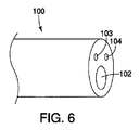
次に図6−図7を参照すると、腹壁ヘルニアを治療するための内視鏡的手法が記載されている。内視鏡的手法は、以上に図3−図5に記載されている腹腔鏡的手法に似ているが、但し、腹腔鏡装置の代わりに内視鏡100が使用され、患者の皮膚には目に見える切開は作成されない。具体的には、図7に描かれている様に、内視鏡100を、消化管の様な身体管腔を通して前進させながら消化管を貫くアクセス孔を作成して、腹腔側からの腹壁ヘルニアへのアクセスを得る。
6-7, an endoscopic technique for treating abdominal wall hernia is described. The endoscopic approach is similar to the laparoscopic approach described above in FIGS. 3-5 except that the
挿入道具50の様な1つ又はそれ以上の構成要素は、内視鏡の作業ルーメン102を通して前進させることができる。挿入道具50の遠位端は、内視鏡100より遠位側を照らし画像を捕捉するために光ファイバー構成要素を備えていてもよいとされる内視鏡100の光学素子103及び104を介して視認することができる。光源と接眼レンズを使用する適した視覚化の下に、医師は挿入道具50を使用して複数の鋲留め装置を1度に1つずつ配備することができる。
One or more components, such as the
この内視鏡的手法が採用される場合、挿入道具50は、後で消化管のアクセス孔を閉合するために追加の鋲留め装置20を担持していてもよい。具体的には、複数の鋲留め装置20の第1のセットが、以上に図3−図5に記載されている様にグラフト部材80を組織74に固定するのに使用され、複数の鋲留め装置20の第2のセットが、消化管のアクセス孔の閉合を促すために使用されるが、その際グラフト部材は使用されても使用されなくてもよい。図7には内視鏡的配備段階の特定の1つの段階しか示されていないが、他の段階は以上に図3−図5に示され説明されており、鋲留め装置20a及び20bの内視鏡的手法を用いての最終的な配備は、以上に図5に描かれているのと実質的に同じであることに留意されたい。
If this endoscopic approach is employed, the
次に図8−図10を参照すると、腹壁ヘルニアを治療するための経皮的手法が記載されている。経皮的手法は、以上に図3−図5に記載されている腹腔鏡的手法と似ているが、幾つかの注目すべき相違点がある。第1に、経皮的手法では、挿入道具50は腹部組織74からグラフト部材80へ向かう方向に進められる。従って、以下に説明されている様に頭領域30が胴領域40に先立って配備される。また、挿入道具50は直接患者の腹部の皮膚を貫いて進められる。
Referring now to FIGS. 8-10, a percutaneous procedure for treating abdominal wall hernia is described. The percutaneous approach is similar to the laparoscopic approach described above in FIGS. 3-5, with some notable differences. First, in the percutaneous technique, the
経皮的手法が使用される場合、鋲留め装置20は、以上に説明されている腹腔鏡的手法及び内視鏡的手法の場合の装填に対してそれとは逆の方向に挿入道具50内に装填されなくてはならない。より具体的には、先の図2に関し、経皮的手法では、1段目の鋲留め装置20aの頭領域30の第1端38が針の尖った先端52に最も近く位置することになる。更に、1段目の鋲留め装置20aの第2端48は、2段目の鋲留め装置20bの第1端38に当接し、スタイレット60は、2段目の鋲留め装置20bの第2端48に当接することになる。
When a percutaneous technique is used, the
構成要素が上述のように装填された状態で、次に、図8に示されている様に、挿入道具50を、直接、患者の腹部の皮膚を貫き、組織74を貫き、グラフト部材80より僅かに遠位へ、腹膜の中まで前進させる。挿入道具50を最適に視覚化するために、先の実施形態で言及されている様に、腹腔鏡的視認装置を腹膜に配置してもよいし、又は内視鏡を経管腔的に目標部位の近傍まで前進させてもよい。代わりに、挿入道具50、特にマーカー56を、他の適した技法のうちの蛍光透視法を使用して視認することもできる。
With the components loaded as described above, the
次の段階では、図2のスタイレット60を挿入道具50に関して固定保持し、その間に挿入道具50を近位方向に、即ち腹膜から遠ざかり組織74に向かう方向に後退させる。これにより、1段目の鋲留め装置20aの第1端38が、挿入道具50の尖った先端52より遠位に伸ばされ、頭領域30が配備される。挿入道具50の尖った先端52をグラフト部材80と整列させることにより、頭領域30は、図9に示されている様に、グラフト部材80と突合接触に配備される。挿入道具50を1段目の鋲留め装置20aに対して近位方向に更に後退させると、胴領域40の第1完周巻き部41が配備され、続いて第2完周巻き部42そして部分周巻き部43が配備される。以上に言及されている様に、展開状態では、完周巻き部41及び42と部分周巻き部43は、組織74に埋まるか又は組織74と織り交ぜられ、それにより胴領域40を組織74の中へ固定することができる。1段目の鋲留め装置20aが配備された後、以上に概説されている様に、穿孔75の周囲周りに追加の鋲留め装置を配備するために挿入装置50を位置変えする。
In the next step, the
以上に言及されている様に、或る代わりの実施形態では、巻き部41の直径が巻き部42の直径より大きくされていて、その結果、胴領域40がねじの様な恰好に先細りしていてもよい。更に代わりの実施形態では、複数の相対的に大径の巻き部が複数の相対的に小径又は中径の巻き部によって区切られていてもよい。例えば、頭領域から胴領域に向けて、相対的に大きい巻き部、次に相対的に小さい巻き部、次に相対的に大きい巻き部、次に中程度の巻き部、そして次に相対的に小さい巻き部という具合に続いていてもよい。幾つかの異なったこの様な巻き部直径の組合せが実施可能である。また、更に代わりの実施形態では、鋲留め装置は、その長手方向の長さ全体に亘って均一の螺旋状の直径を備えていてもよい。
As mentioned above, in an alternative embodiment, the diameter of the
例示としての実施形態は、ここでは、腹部前壁に形成された穿孔75を覆う場合の1つ又はそれ以上の鋲留め装置20の使用を説明しているが、ここに開示されている鋲留め装置は、他の多くの処置で有用であろう。単に一例として、1つ又はそれ以上の鋲留め装置20は、胃壁の様な臓器壁の穿孔を治療するのに使用することができる。更に、鋲留め装置20は、局所組織を再建するなどで組織にグラフト部材を固定するのに使用することもできる。
The exemplary embodiment here describes the use of one or
本発明の範囲内での更に別の適用では、鋲留め装置20はグラフト部材を組織に結合することのために使用される必要はない。例えば、鋲留め装置20は、吻合処置に使用されてもよい。吻合を作成するために、例えば、近位側の脈管、管道、又は器官を、遠位側の脈管、管道、又は器官に結合するべく、複数の鋲留め装置20が円形式に配備されてもよい。その様な事例では、内視鏡の様な適した挿入装置が、消化管の様な身体管腔を通して目標場所に近接する位置まで進められる。挿入道具50の様な1つ又はそれ以上の構成要素は、内視鏡の作業ルーメンを通して進めることができる。挿入道具50の遠位端は、蛍光透視法下に、又は内視鏡の光学素子を介して、又は何か他の視覚化技法を介して、視認することができる。適した視覚化の下に、次いで複数の鋲留め装置要素が、例えば挿入道具50を使用して、一度に送達される。次に、配備されたそれら鋲留め装置の真ん中を貫いて孔が開けられ、近位側と遠位側の脈管/管道/器官同士の間に流れの経路が作成される。
In yet another application within the scope of the present invention, the staking
鋲留め装置20の更に別の適用が実施可能であることは自明であろう。最後に、例示としての腹腔鏡的、内視鏡的、及び経皮的な送達技法を記載してきたが、ここに記載されている鋲留め装置20は開放性医療処置中に目標部位に配備されてもよいことに留意されたい。
It will be obvious that further applications of the tacking
更に当業者には認識される様に、以上に記載されている方法は、概して、装置を、体内管腔を通して組織に設置することを含んでいるが、本システム、装置、及び方法は、人間又は動物の身体及び身体管腔に関連し得る材料かそうでないかを問わず、如何なる材料(例えば、織物、布、ポリマー、エラストマー、プラスチック、及びゴム)の層に使用されてもよいことが認識されるであろう。例えば、本システム、装置、及び方法に関しては、研究施設及び産業環境で、人間又は動物の身体への適用が見い出され得る材料かそうでないかを問わず、1層又はそれ以上の材料の層を通して装置を設置する場合の利用、及び同様に、身体組織ではない材料の層の孔又は穿孔を閉合する場合の利用を見い出すことができる。幾つかの例として、縫製又は縫合及び関連の製造工程、合成組織を用いた作業、ポリマーシートの接続又は修復、動物の研究、獣医学的適用、及び死体解剖活動が挙げられる。 As will be further appreciated by those skilled in the art, the methods described above generally include placing the device in tissue through a body lumen, although the systems, devices, and methods are human. Or it may be used for layers of any material (eg, fabrics, cloths, polymers, elastomers, plastics, and rubbers), whether or not they can be associated with the animal body and body lumen Will be done. For example, with respect to the present systems, devices, and methods, through one or more layers of materials, whether or not materials that can find application to the human or animal body in research facilities and industrial environments. Applications can be found when installing the device, and likewise when closing holes or perforations in layers of material that are not body tissue. Some examples include sewing or suturing and related manufacturing processes, working with synthetic tissue, connecting or repairing polymer sheets, animal studies, veterinary applications, and cadaveric activities.
本発明の様々な実施形態を記載してきたが、本発明は、付随の特許請求の範囲及びそれらの等価物に照らした場合を除き限定されるものではない。更に、ここに記載されている利点は必ずしも本発明の唯一の利点というわけではなく、また必ずしも本発明の実施形態のどれもが、記載されている利点の全てを実現できるものと期待されているわけではない。 While various embodiments of the invention have been described, the invention is not limited except in light of the appended claims and their equivalents. Further, the advantages described herein are not necessarily the only advantages of the present invention, and it is expected that any embodiment of the present invention will realize all of the described advantages. Do not mean.
20、20a、20b 鋲留め装置
21 ワイヤ
30 頭領域
32 実質的直線区間
33 湾曲区間
34 実質的直線区間に平行の部分
35 連接部
38、38’ 第1端
40 胴領域
41、42 完周巻き部
43 部分周巻き部
48 第2端
49 内部空間
50 挿入道具
52 挿入道具の尖った先端
54 挿入道具のルーメン
56 マーカー
60 スタイレット
74 組織
75 穿孔
80グラフト部材
90 腹腔鏡装置
100 内視鏡
102 作業ルーメン
103、104 光学素子
C 長手方向中心軸
D1 頭領域の巻き部の直径
D2 胴領域の巻き部の直径
L1 頭領域の長手方向距離
L2 胴領域の長手方向距離
t1 組織の厚さ
t2 グラフト部材の厚さ
20, 20a,
Claims (19)
前記送達状態では、前記ワイヤは、直線的な細長い形態を備え、
前記配備状態では、前記ワイヤは、頭領域と胴領域とを備え、前記頭領域は第1直径を有する少なくとも1つの完周巻き部を備え、前記胴領域は第2直径を有する少なくとも2つの完周巻き部を備えており、前記第1直径は前記第2直径より大きい、鋲留め装置。 A tacking device comprising a wire having a first end and a second end and further having a delivery state and a deployed state.
In the delivery state, the wire comprises a straight elongated form;
In the deployed state, the wire comprises a head region and a torso region, the head region comprising at least one complete winding having a first diameter, and the torso region comprising at least two complete turns having a second diameter. A ratchet device comprising a circumferential winding, wherein the first diameter is greater than the second diameter.
前記グラフト部材を前記材料の層の選択された領域を覆って位置付ける段階と、
送達状態と配備状態とを有するワイヤを備えた少なくとも1つの鋲留め装置を提供する段階と、
送達装置の中空ルーメン内の鋲留め装置を送達する段階であって、前記ワイヤは直線的な細長い形態を有する前記送達状態で提供されている、鋲留め装置を送達する段階と、
前記挿入道具と前記鋲留め装置を互いに対して動かして、前記ワイヤを前記挿入道具から排出させ、配備状態に配備する段階と、を備えており、
前記配備状態では、前記ワイヤは、前記グラフト部材に当接している少なくとも1つの完周巻き部を備える頭領域を備え、更に、前記材料の層に係合している少なくとも2つの完周巻き部を備える胴領域を備えている、方法。 In a suitable method for bonding the graft member to the layer of material,
Positioning the graft member over a selected region of the layer of material;
Providing at least one tacking device with a wire having a delivery state and a deployed state;
Delivering a tacking device within a hollow lumen of the delivery device, wherein the wire is provided in the delivery state having a straight elongated configuration;
Moving the insertion tool and the clamping device relative to each other to eject the wire from the insertion tool and deploying it in a deployed state; and
In the deployed state, the wire includes a head region with at least one full turn that abuts the graft member, and further includes at least two complete turns that are engaged with the layer of material. A method comprising a torso region comprising:
前記送達状態では、前記ワイヤは直線的な細長い形態を備え、
前記配備状態では、前記ワイヤは、頭領域と胴領域とそれらの間に配置されている連接部とを備え、前記頭領域は少なくとも1つの完周巻き部を備え、前記胴領域は少なくとも2つの完周巻き部を備え、
前記連接部は、前記ワイヤの湾曲の方向を時計回りの方向から反時計回りの方向へ変化させている、鋲留め装置。 A tacking device comprising a wire having a first end and a second end and further having a delivery state and a deployed state.
In the delivery state, the wire has a straight elongated form;
In the deployed state, the wire comprises a head region, a torso region, and a connecting portion disposed therebetween, the head region comprising at least one complete winding, and the torso region comprising at least two torso regions. It has a complete winding part,
The brazing device is configured to change the bending direction of the wire from a clockwise direction to a counterclockwise direction.
Applications Claiming Priority (3)
| Application Number | Priority Date | Filing Date | Title |
|---|---|---|---|
| US18194609P | 2009-05-28 | 2009-05-28 | |
| US61/181,946 | 2009-05-28 | ||
| PCT/US2010/036188 WO2010138579A1 (en) | 2009-05-28 | 2010-05-26 | Tacking device and methods of deployment |
Publications (2)
| Publication Number | Publication Date |
|---|---|
| JP2012527970A true JP2012527970A (en) | 2012-11-12 |
| JP2012527970A5 JP2012527970A5 (en) | 2013-07-18 |
Family
ID=42629531
Family Applications (1)
| Application Number | Title | Priority Date | Filing Date |
|---|---|---|---|
| JP2012513205A Pending JP2012527970A (en) | 2009-05-28 | 2010-05-26 | Hail-fastening device and hail-fastening device deployment method |
Country Status (6)
| Country | Link |
|---|---|
| US (1) | US9345476B2 (en) |
| EP (1) | EP2434960A1 (en) |
| JP (1) | JP2012527970A (en) |
| AU (1) | AU2010254151B2 (en) |
| CA (1) | CA2763133A1 (en) |
| WO (1) | WO2010138579A1 (en) |
Families Citing this family (4)
| Publication number | Priority date | Publication date | Assignee | Title |
|---|---|---|---|---|
| EP3129376B1 (en) | 2014-03-27 | 2018-12-26 | Janssen Pharmaceutica NV | Substituted 4,5,6,7-tetrahydro-pyrazolo[1,5-a]pyrazine derivatives and 5,6,7,8-tetrahydro-4h-pyrazolo[1,5-a][1,4]diazepine derivatives as ros1 inhibitors |
| US10028733B2 (en) | 2015-05-28 | 2018-07-24 | National University Of Ireland, Galway | Fistula treatment device |
| US11701096B2 (en) | 2015-05-28 | 2023-07-18 | National University Of Ireland, Galway | Fistula treatment device |
| EP3831308A1 (en) | 2017-06-09 | 2021-06-09 | Signum Surgical Limited | An implant for closing an opening in tissue |
Citations (8)
| Publication number | Priority date | Publication date | Assignee | Title |
|---|---|---|---|---|
| JPH0833640A (en) * | 1994-01-13 | 1996-02-06 | Ethicon Inc | Spiral-form surgical tack and application therefor |
| JPH10506026A (en) * | 1994-08-05 | 1998-06-16 | オリジン メドシステムズ インコーポレイテッド | Spiral spiral fastener and applicator |
| JP2000514336A (en) * | 1996-07-16 | 2000-10-31 | アンソン メディカル リミテッド | Surgical implant and delivery system therefor |
| JP2002522107A (en) * | 1998-08-03 | 2002-07-23 | アンソン メディカル リミテッド | Arterial repair device and method |
| JP2003517869A (en) * | 1999-12-23 | 2003-06-03 | スワミナサン ジャヤラマン | Manufacture and delivery of occlusive coils |
| WO2007005996A2 (en) * | 2005-07-05 | 2007-01-11 | Ovalis, Inc. | Systems and methods for treating septal defects |
| WO2007070753A2 (en) * | 2005-12-05 | 2007-06-21 | Ovalis, Inc. | Clip-based systems and methods for treating septal defects |
| JP2010017542A (en) * | 2008-07-11 | 2010-01-28 | Olympus Medical Systems Corp | Tissue fastening tool |
Family Cites Families (272)
| Publication number | Priority date | Publication date | Assignee | Title |
|---|---|---|---|---|
| US2199025A (en) | 1936-06-08 | 1940-04-30 | Carl E Conn | Means and method of closing surgical incisions |
| US2671444A (en) | 1951-12-08 | 1954-03-09 | Jr Benjamin F Pease | Nonmetallic mesh surgical insert for hernia repair |
| US3209422A (en) | 1963-12-23 | 1965-10-05 | Dritz Arthur | Fastening device |
| US3399432A (en) | 1965-12-08 | 1968-09-03 | Dennison Mfg Co | Button attachment |
| US3556079A (en) | 1967-05-16 | 1971-01-19 | Haruo Omizo | Method of puncturing a medical instrument under guidance of ultrasound |
| US3470834A (en) | 1968-03-08 | 1969-10-07 | Dennison Mfg Co | Fastener attaching device |
| US3814104A (en) | 1971-07-05 | 1974-06-04 | W Irnich | Pacemaker-electrode |
| US3856016A (en) | 1972-11-03 | 1974-12-24 | H Davis | Method for mechanically applying an occlusion clip to an anatomical tubular structure |
| US3954108A (en) | 1972-11-03 | 1976-05-04 | Davis Hugh J | Occlusion clip and instrument for applying same |
| JPS5320957Y2 (en) | 1973-11-14 | 1978-06-01 | ||
| US4006747A (en) | 1975-04-23 | 1977-02-08 | Ethicon, Inc. | Surgical method |
| SU715082A1 (en) | 1977-01-24 | 1980-02-15 | Всесоюзный научно-исследовательский и испытательный институт медицинской техники | Surgical suturing apparatus |
| US4217902A (en) | 1977-05-02 | 1980-08-19 | March Alfred L | Hemostatic clip |
| US4235238A (en) | 1978-05-11 | 1980-11-25 | Olympus Optical Co., Ltd. | Apparatus for suturing coeliac tissues |
| US4485816A (en) | 1981-06-25 | 1984-12-04 | Alchemia | Shape-memory surgical staple apparatus and method for use in surgical suturing |
| US4621639A (en) | 1982-02-03 | 1986-11-11 | Ethicon, Inc | Surgical instrument with hydraulic actuator |
| US5417691A (en) | 1982-05-20 | 1995-05-23 | Hayhurst; John O. | Apparatus and method for manipulating and anchoring tissue |
| CH668691A5 (en) | 1985-05-31 | 1989-01-31 | Alice Dr Med Utz | WIND CLASP. |
| US5123914A (en) | 1986-05-19 | 1992-06-23 | Cook Incorporated | Visceral anchor for visceral wall mobilization |
| US4796627A (en) | 1986-08-26 | 1989-01-10 | Tucker Wilson H | Clip applicator and spreadable clips for use therein |
| US4791707A (en) | 1986-08-26 | 1988-12-20 | Tucker Wilson H | Clip applicator, spreadable clips and method for applying the clips |
| US4749114A (en) | 1986-11-10 | 1988-06-07 | United States Surgical Corporation | Purse string applicator and method of affixing a purse string |
| US4898156A (en) | 1987-05-18 | 1990-02-06 | Mitek Surgical Products, Inc. | Suture anchor |
| US4773420A (en) | 1987-06-22 | 1988-09-27 | U.S. Surgical Corporation | Purse string applicator |
| US4821939A (en) | 1987-09-02 | 1989-04-18 | United States Surgical Corporation | Staple cartridge and an anvilless surgical stapler |
| SE460455B (en) | 1987-09-30 | 1989-10-16 | Astra Meditec Ab | SURGICAL INSTRUMENT FOR BONDING INTERNAL WEAVES |
| US5084057A (en) | 1989-07-18 | 1992-01-28 | United States Surgical Corporation | Apparatus and method for applying surgical clips in laparoscopic or endoscopic procedures |
| US5100420A (en) | 1989-07-18 | 1992-03-31 | United States Surgical Corporation | Apparatus and method for applying surgical clips in laparoscopic or endoscopic procedures |
| FR2632848A1 (en) | 1988-06-21 | 1989-12-22 | Lefebvre Jean Marie | FILTER FOR MEDICAL USE |
| AU4312189A (en) | 1988-09-16 | 1990-04-02 | P. Kevin Maughan | Surgical clip |
| US4994069A (en) * | 1988-11-02 | 1991-02-19 | Target Therapeutics | Vaso-occlusion coil and method |
| US5059205A (en) | 1989-09-07 | 1991-10-22 | Boston Scientific Corporation | Percutaneous anti-migration vena cava filter |
| DE3941108C1 (en) | 1989-12-13 | 1991-06-27 | Richard Wolf Gmbh, 7134 Knittlingen, De | |
| US5049153A (en) | 1989-12-26 | 1991-09-17 | Nakao Naomi L | Endoscopic stapling device and method |
| US5015249A (en) | 1989-12-26 | 1991-05-14 | Nakao Naomi L | Endoscopic stapling device and method |
| US5156609A (en) | 1989-12-26 | 1992-10-20 | Nakao Naomi L | Endoscopic stapling device and method |
| US5324307A (en) | 1990-07-06 | 1994-06-28 | American Cyanamid Company | Polymeric surgical staple |
| US5203787A (en) | 1990-11-19 | 1993-04-20 | Biomet, Inc. | Suture retaining arrangement |
| US5366480A (en) | 1990-12-24 | 1994-11-22 | American Cyanamid Company | Synthetic elastomeric buttressing pledget |
| CA2079057A1 (en) | 1991-10-18 | 1993-04-19 | Stanley H. Remiszewski | Surgical stapling apparatus |
| US5242456A (en) | 1991-11-21 | 1993-09-07 | Kensey Nash Corporation | Apparatus and methods for clamping tissue and reflecting the same |
| ES2133382T3 (en) | 1992-01-21 | 1999-09-16 | Univ Minnesota | DEVICE FOR THE CLOSURE OF SEPTAL DEFECTS. |
| US5333624A (en) | 1992-02-24 | 1994-08-02 | United States Surgical Corporation | Surgical attaching apparatus |
| US5484451A (en) | 1992-05-08 | 1996-01-16 | Ethicon, Inc. | Endoscopic surgical instrument and staples for applying purse string sutures |
| US5766246A (en) | 1992-05-20 | 1998-06-16 | C. R. Bard, Inc. | Implantable prosthesis and method and apparatus for loading and delivering an implantable prothesis |
| US5437266A (en) | 1992-07-02 | 1995-08-01 | Mcpherson; William | Coil screw surgical retractor |
| IL103737A (en) | 1992-11-13 | 1997-02-18 | Technion Res & Dev Foundation | Stapler device particularly useful in medical suturing |
| US5368602A (en) | 1993-02-11 | 1994-11-29 | De La Torre; Roger A. | Surgical mesh with semi-rigid border members |
| US5342396A (en) | 1993-03-02 | 1994-08-30 | Cook Melvin S | Staples |
| US5350385A (en) | 1993-04-28 | 1994-09-27 | Christy William J | Surgical stab wound closure device and method |
| US6241747B1 (en) | 1993-05-03 | 2001-06-05 | Quill Medical, Inc. | Barbed Bodily tissue connector |
| US5403348A (en) | 1993-05-14 | 1995-04-04 | Bonutti; Peter M. | Suture anchor |
| US5368600A (en) | 1993-07-23 | 1994-11-29 | Ethicon, Inc. | Steerable bulldog clamp applier |
| EP0673229A4 (en) | 1993-08-25 | 1996-09-11 | Life Surgery Inc | Surgical ligation clip. |
| US5411522A (en) | 1993-08-25 | 1995-05-02 | Linvatec Corporation | Unitary anchor for soft tissue fixation |
| IT1269443B (en) | 1994-01-19 | 1997-04-01 | Stefano Nazari | VASCULAR PROSTHESIS FOR THE REPLACEMENT OR INTERNAL COATING OF MEDIUM AND LARGE DIAMETER BLOOD VESSELS AND DEVICE FOR ITS APPLICATION WITHOUT INTERRUPTION OF BLOOD FLOW |
| CH687060A5 (en) | 1994-02-11 | 1996-09-13 | Alice Walder Utz Dr | Piece surgical clip. |
| US5824044A (en) | 1994-05-12 | 1998-10-20 | Endovascular Technologies, Inc. | Bifurcated multicapsule intraluminal grafting system |
| US5573542A (en) | 1994-08-17 | 1996-11-12 | Tahoe Surgical Instruments-Puerto Rico | Endoscopic suture placement tool |
| CA2199864C (en) | 1994-09-16 | 2006-06-20 | Seth A. Foerster | Methods and devices for defining and marking tissue |
| JPH08196538A (en) | 1994-09-26 | 1996-08-06 | Ethicon Inc | Tissue sticking apparatus for surgery with elastomer component and method of attaching mesh for surgery to said tissue |
| US5766184A (en) | 1994-11-02 | 1998-06-16 | Olympus Optical Co., Ltd. | Endoscopic treatment tool |
| US6110187A (en) | 1995-02-24 | 2000-08-29 | Heartport, Inc. | Device and method for minimizing heart displacements during a beating heart surgical procedure |
| US5976159A (en) | 1995-02-24 | 1999-11-02 | Heartport, Inc. | Surgical clips and methods for tissue approximation |
| US5904697A (en) | 1995-02-24 | 1999-05-18 | Heartport, Inc. | Devices and methods for performing a vascular anastomosis |
| US6132438A (en) | 1995-06-07 | 2000-10-17 | Ep Technologies, Inc. | Devices for installing stasis reducing means in body tissue |
| US5690656A (en) | 1995-06-27 | 1997-11-25 | Cook Incorporated | Method and apparatus for creating abdominal visceral anastomoses |
| US5662683A (en) | 1995-08-22 | 1997-09-02 | Ortho Helix Limited | Open helical organic tissue anchor and method of facilitating healing |
| US5782865A (en) | 1995-08-25 | 1998-07-21 | Grotz; Robert Thomas | Stabilizer for human joints |
| US5674231A (en) | 1995-10-20 | 1997-10-07 | United States Surgical Corporation | Apparatus and method for vascular hole closure |
| US5582615A (en) | 1995-10-30 | 1996-12-10 | Pilling Weck, Incorporated | Handle for surgical clip applicator systems |
| US5810848A (en) | 1996-08-21 | 1998-09-22 | Hayhurst; John O. | Suturing system |
| SK22499A3 (en) | 1996-08-23 | 1999-10-08 | Cook Biotech Inc | Graft prosthesis, materials and methods |
| US5868763A (en) | 1996-09-16 | 1999-02-09 | Guidant Corporation | Means and methods for performing an anastomosis |
| WO1998018389A1 (en) | 1996-10-25 | 1998-05-07 | University Of Massachusetts | Surgical vessel clips and methods for closing vessels |
| US6036702A (en) | 1997-04-23 | 2000-03-14 | Vascular Science Inc. | Medical grafting connectors and fasteners |
| US6447530B1 (en) | 1996-11-27 | 2002-09-10 | Scimed Life Systems, Inc. | Atraumatic anchoring and disengagement mechanism for permanent implant device |
| CA2224366C (en) | 1996-12-11 | 2006-10-31 | Ethicon, Inc. | Meniscal repair device |
| US6149658A (en) | 1997-01-09 | 2000-11-21 | Coalescent Surgical, Inc. | Sutured staple surgical fasteners, instruments and methods for minimally invasive vascular and endoscopic surgery |
| US5891159A (en) | 1997-05-02 | 1999-04-06 | Cardiothoratic Systems, Inc. | Automatic purse string suture device |
| US6071292A (en) | 1997-06-28 | 2000-06-06 | Transvascular, Inc. | Transluminal methods and devices for closing, forming attachments to, and/or forming anastomotic junctions in, luminal anatomical structures |
| US5984949A (en) | 1997-10-06 | 1999-11-16 | Levin; John M. | Tissue hooks and tools for applying same |
| US6994713B2 (en) | 1998-01-30 | 2006-02-07 | St. Jude Medical Atg, Inc. | Medical graft connector or plug structures, and methods of making and installing same |
| US6638234B2 (en) | 1998-03-03 | 2003-10-28 | Senorx, Inc. | Sentinel node location and biopsy |
| AU737877B2 (en) | 1998-05-21 | 2001-09-06 | Christopher J. Walshe | A tissue anchor system |
| WO2000056227A1 (en) | 1999-03-19 | 2000-09-28 | By-Pass, Inc. | Advanced closure device |
| US7060084B1 (en) | 1998-05-29 | 2006-06-13 | By-Pass, Inc. | Vascular closure device |
| WO1999062408A1 (en) | 1998-05-29 | 1999-12-09 | By-Pass, Inc. | Vascular port device |
| US20040087985A1 (en) | 1999-03-19 | 2004-05-06 | Amir Loshakove | Graft and connector delivery |
| US20050283188A1 (en) | 1998-05-29 | 2005-12-22 | By-Pass, Inc. | Vascular closure device |
| US5972002A (en) | 1998-06-02 | 1999-10-26 | Cabot Technology Corporation | Apparatus and method for surgical ligation |
| US6165183A (en) | 1998-07-15 | 2000-12-26 | St. Jude Medical, Inc. | Mitral and tricuspid valve repair |
| US6206913B1 (en) | 1998-08-12 | 2001-03-27 | Vascular Innovations, Inc. | Method and system for attaching a graft to a blood vessel |
| US6679851B2 (en) | 1998-09-01 | 2004-01-20 | Senorx, Inc. | Tissue accessing and anchoring device and method |
| JP2002526193A (en) | 1998-09-18 | 2002-08-20 | ユナイテッド ステイツ サージカル コーポレーション | Intravascular fastener applicator |
| US6551340B1 (en) | 1998-10-09 | 2003-04-22 | Board Of Regents The University Of Texas System | Vasoocclusion coil device having a core therein |
| US6152937A (en) | 1998-11-06 | 2000-11-28 | St. Jude Medical Cardiovascular Group, Inc. | Medical graft connector and methods of making and installing same |
| US6113612A (en) | 1998-11-06 | 2000-09-05 | St. Jude Medical Cardiovascular Group, Inc. | Medical anastomosis apparatus |
| US6371963B1 (en) | 1998-11-17 | 2002-04-16 | Scimed Life Systems, Inc. | Device for controlled endoscopic penetration of injection needle |
| US7410460B2 (en) | 1998-11-23 | 2008-08-12 | Benderev Theodore V | System for securing sutures, grafts and soft tissue to bone and periosteum |
| AU736964B2 (en) | 1998-12-09 | 2001-08-09 | Cook Medical Technologies Llc | Hollow, curved, superelastic medical needle |
| US6110183A (en) | 1998-12-22 | 2000-08-29 | Cook Incorporated | Suture anchor device |
| US9295581B2 (en) | 1999-01-05 | 2016-03-29 | Second Sight Medical Products, Inc. | Medical tack with a variable effective length |
| US6193732B1 (en) | 1999-01-08 | 2001-02-27 | Cardiothoracic System | Surgical clips and apparatus and method for clip placement |
| US6228097B1 (en) | 1999-01-22 | 2001-05-08 | Scion International, Inc. | Surgical instrument for clipping and cutting blood vessels and organic structures |
| US6159223A (en) | 1999-01-26 | 2000-12-12 | Endoscopic Concepts, Inc. | Surgical clip applicator |
| EP1171042A1 (en) | 1999-03-19 | 2002-01-16 | By-Pass, Inc. | Vascular surgery |
| WO2000060995A2 (en) | 1999-04-09 | 2000-10-19 | Evalve, Inc. | Methods and apparatus for cardiac valve repair |
| US7666204B2 (en) | 1999-04-09 | 2010-02-23 | Evalve, Inc. | Multi-catheter steerable guiding system and methods of use |
| JP2000300571A (en) * | 1999-04-19 | 2000-10-31 | Nissho Corp | Closure plug for transcatheter operation |
| US6482178B1 (en) | 1999-05-21 | 2002-11-19 | Cook Urological Incorporated | Localization device with anchoring barbs |
| US6699256B1 (en) | 1999-06-04 | 2004-03-02 | St. Jude Medical Atg, Inc. | Medical grafting apparatus and methods |
| US7416554B2 (en) | 2002-12-11 | 2008-08-26 | Usgi Medical Inc | Apparatus and methods for forming and securing gastrointestinal tissue folds |
| US8574243B2 (en) | 1999-06-25 | 2013-11-05 | Usgi Medical, Inc. | Apparatus and methods for forming and securing gastrointestinal tissue folds |
| US7618426B2 (en) | 2002-12-11 | 2009-11-17 | Usgi Medical, Inc. | Apparatus and methods for forming gastrointestinal tissue approximations |
| CA2381818C (en) | 1999-09-13 | 2009-08-04 | Rex Medical, L.P. | Vascular closure |
| US6368328B1 (en) | 1999-09-16 | 2002-04-09 | Scimed Life Systems, Inc. | Laser-resistant medical retrieval device |
| US6231561B1 (en) | 1999-09-20 | 2001-05-15 | Appriva Medical, Inc. | Method and apparatus for closing a body lumen |
| US6911032B2 (en) | 1999-11-18 | 2005-06-28 | Scimed Life Systems, Inc. | Apparatus and method for compressing body tissue |
| US6428548B1 (en) | 1999-11-18 | 2002-08-06 | Russell F. Durgin | Apparatus and method for compressing body tissue |
| US6635073B2 (en) | 2000-05-03 | 2003-10-21 | Peter M. Bonutti | Method of securing body tissue |
| US6623492B1 (en) | 2000-01-25 | 2003-09-23 | Smith & Nephew, Inc. | Tissue fastener |
| GB2359024A (en) | 2000-02-09 | 2001-08-15 | Anson Medical Ltd | Fixator for arteries |
| US6387114B2 (en) | 2000-04-28 | 2002-05-14 | Scimed Life Systems, Inc. | Gastrointestinal compression clips |
| US6468290B1 (en) | 2000-06-05 | 2002-10-22 | Scimed Life Systems, Inc. | Two-planar vena cava filter with self-centering capabilities |
| IL136702A (en) | 2000-06-12 | 2005-11-20 | Niti Alloys Tech Ltd | Surgical clip |
| US6572629B2 (en) | 2000-08-17 | 2003-06-03 | Johns Hopkins University | Gastric reduction endoscopy |
| US6746458B1 (en) | 2000-09-07 | 2004-06-08 | William G. Cloud | Mesh material to repair hernias |
| US20060106279A1 (en) | 2004-05-14 | 2006-05-18 | Ample Medical, Inc. | Devices, systems, and methods for reshaping a heart valve annulus, including the use of a bridge implant having an adjustable bridge stop |
| US6736828B1 (en) | 2000-09-29 | 2004-05-18 | Scimed Life Systems, Inc. | Method for performing endoluminal fundoplication and apparatus for use in the method |
| US7485124B2 (en) | 2000-10-19 | 2009-02-03 | Ethicon Endo-Surgery, Inc. | Surgical instrument having a fastener delivery mechanism |
| US6425900B1 (en) | 2000-10-19 | 2002-07-30 | Ethicon Endo-Surgery | Method for attaching hernia mesh |
| US6551333B2 (en) | 2000-10-19 | 2003-04-22 | Ethicon Endo-Surgery, Inc. | Method for attaching hernia mesh |
| US7232445B2 (en) | 2000-12-06 | 2007-06-19 | Id, Llc | Apparatus for the endoluminal treatment of gastroesophageal reflux disease (GERD) |
| US7211101B2 (en) | 2000-12-07 | 2007-05-01 | Abbott Vascular Devices | Methods for manufacturing a clip and clip |
| US6719777B2 (en) | 2000-12-07 | 2004-04-13 | Integrated Vascular Systems, Inc. | Closure device and methods for making and using them |
| US6623510B2 (en) | 2000-12-07 | 2003-09-23 | Integrated Vascular Systems, Inc. | Closure device and methods for making and using them |
| US6695867B2 (en) | 2002-02-21 | 2004-02-24 | Integrated Vascular Systems, Inc. | Plunger apparatus and methods for delivering a closure device |
| US7806904B2 (en) | 2000-12-07 | 2010-10-05 | Integrated Vascular Systems, Inc. | Closure device |
| US20020173803A1 (en) | 2001-05-01 | 2002-11-21 | Stephen Ainsworth | Self-closing surgical clip for tissue |
| EP1392179B1 (en) | 2001-05-18 | 2009-09-23 | UCL Business PLC | A flexible device for transfixing and joining tissue |
| US6808491B2 (en) | 2001-05-21 | 2004-10-26 | Syntheon, Llc | Methods and apparatus for on-endoscope instruments having end effectors and combinations of on-endoscope and through-endoscope instruments |
| US7727248B2 (en) | 2001-06-25 | 2010-06-01 | Ethicon Endo-Surgery, Inc. | Surgical clip |
| US20080015633A1 (en) * | 2001-09-06 | 2008-01-17 | Ryan Abbott | Systems and Methods for Treating Septal Defects |
| US20050090837A1 (en) | 2003-03-25 | 2005-04-28 | Sixto Robert Jr. | Endoscopic surgical instrument having a force limiting actuator |
| US6699263B2 (en) | 2002-04-05 | 2004-03-02 | Cook Incorporated | Sliding suture anchor |
| US7494496B2 (en) | 2002-05-17 | 2009-02-24 | Ucl Biomedica Plc | Device for transfixing and joining tissue |
| US7867252B2 (en) | 2002-06-11 | 2011-01-11 | Tyco Healthcare Group Lp | Hernia mesh tacks |
| CA2489508C (en) | 2002-06-19 | 2011-03-29 | Tyco Healthcare Group Lp | Method and apparatus for anastomosis |
| US7112214B2 (en) | 2002-06-25 | 2006-09-26 | Incisive Surgical, Inc. | Dynamic bioabsorbable fastener for use in wound closure |
| JP4373146B2 (en) | 2002-07-11 | 2009-11-25 | オリンパス株式会社 | Endoscopic suturing device |
| US6746460B2 (en) | 2002-08-07 | 2004-06-08 | Satiety, Inc. | Intra-gastric fastening devices |
| US7727247B2 (en) | 2002-08-21 | 2010-06-01 | Olympus Corporation | Living tissue ligation device |
| US7351250B2 (en) | 2002-08-21 | 2008-04-01 | Kci Licensing, Inc. | Circumferential medical closure device and method |
| US20040044364A1 (en) * | 2002-08-29 | 2004-03-04 | Devries Robert | Tissue fasteners and related deployment systems and methods |
| US8454628B2 (en) | 2002-09-20 | 2013-06-04 | Syntheon, Llc | Surgical fastener aligning instrument particularly for transoral treatment of gastroesophageal reflux disease |
| US20060025788A1 (en) | 2002-09-25 | 2006-02-02 | By-Pass, Inc. | Anastomotic leg arrangement |
| US6966916B2 (en) | 2002-09-26 | 2005-11-22 | Kumar Sarbjeet S | Device and method for surgical repair of abdominal wall hernias |
| US8105345B2 (en) | 2002-10-04 | 2012-01-31 | Medtronic, Inc. | Anastomosis apparatus and methods |
| US20060015125A1 (en) | 2004-05-07 | 2006-01-19 | Paul Swain | Devices and methods for gastric surgery |
| EP1596723A2 (en) | 2003-02-04 | 2005-11-23 | ev3 Sunnyvale, Inc. | Patent foramen ovale closure system |
| JP4145200B2 (en) | 2003-06-06 | 2008-09-03 | オリンパス株式会社 | Suture device |
| EP1635723B1 (en) | 2003-06-13 | 2011-08-10 | Tyco Healthcare Group LP | Multiple member interconnect for surgical instrument and absorbable screw fastener |
| DE10336734A1 (en) | 2003-08-11 | 2005-03-10 | Siemens Ag | Tissue anchor for endorobots |
| US20050043749A1 (en) | 2003-08-22 | 2005-02-24 | Coalescent Surgical, Inc. | Eversion apparatus and methods |
| US20050075654A1 (en) | 2003-10-06 | 2005-04-07 | Brian Kelleher | Methods and devices for soft tissue securement |
| US20050273119A1 (en) * | 2003-12-09 | 2005-12-08 | Nmt Medical, Inc. | Double spiral patent foramen ovale closure clamp |
| US20050251189A1 (en) | 2004-05-07 | 2005-11-10 | Usgi Medical Inc. | Multi-position tissue manipulation assembly |
| US7361180B2 (en) | 2004-05-07 | 2008-04-22 | Usgi Medical, Inc. | Apparatus for manipulating and securing tissue |
| US7618427B2 (en) | 2003-12-29 | 2009-11-17 | Ethicon Endo-Surgery, Inc. | Device and method for intralumenal anastomosis |
| JP4643451B2 (en) | 2004-01-08 | 2011-03-02 | オリンパス株式会社 | Anastomosis |
| EP1713402B1 (en) | 2004-02-13 | 2018-07-04 | Ethicon Endo-Surgery, Inc. | Device for reducing stomach volume |
| JP4643328B2 (en) | 2004-04-07 | 2011-03-02 | オリンパス株式会社 | Medical ligature suturing device |
| US7833238B2 (en) | 2004-04-19 | 2010-11-16 | Granit Medical Innovations, Llc | Endoscopic anchoring device and associated method |
| US8114099B2 (en) | 2004-04-27 | 2012-02-14 | Tyco Healthcare Group Lp | Absorbable anchor for hernia mesh fixation |
| US7758612B2 (en) | 2004-04-27 | 2010-07-20 | Tyco Healthcare Group Lp | Surgery delivery device and mesh anchor |
| US7842053B2 (en) * | 2004-05-06 | 2010-11-30 | Nmt Medical, Inc. | Double coil occluder |
| US7736374B2 (en) | 2004-05-07 | 2010-06-15 | Usgi Medical, Inc. | Tissue manipulation and securement system |
| US20050251205A1 (en) | 2004-05-07 | 2005-11-10 | Usgi Medical Inc. | Apparatus and methods for positioning and securing anchors |
| EP1750595A4 (en) | 2004-05-07 | 2008-10-22 | Valentx Inc | Devices and methods for attaching an endolumenal gastrointestinal implant |
| US7390329B2 (en) | 2004-05-07 | 2008-06-24 | Usgi Medical, Inc. | Methods for grasping and cinching tissue anchors |
| US20060004410A1 (en) | 2004-05-14 | 2006-01-05 | Nobis Rudolph H | Suture locking and cutting devices and methods |
| WO2005110241A1 (en) | 2004-05-14 | 2005-11-24 | Ethicon Endo-Surgery, Inc. | Devices for locking and/or cutting a suture |
| US20080091059A1 (en) | 2004-05-14 | 2008-04-17 | Ample Medical, Inc. | Devices, systems, and methods for reshaping a heart valve annulus, including the use of a bridge implant having an adjustable bridge stop |
| US8475476B2 (en) | 2004-06-01 | 2013-07-02 | Cook Medical Technologies Llc | System and method for accessing a body cavity |
| US7678135B2 (en) | 2004-06-09 | 2010-03-16 | Usgi Medical, Inc. | Compressible tissue anchor assemblies |
| US7736379B2 (en) | 2004-06-09 | 2010-06-15 | Usgi Medical, Inc. | Compressible tissue anchor assemblies |
| US8206417B2 (en) | 2004-06-09 | 2012-06-26 | Usgi Medical Inc. | Apparatus and methods for optimizing anchoring force |
| US7695493B2 (en) | 2004-06-09 | 2010-04-13 | Usgi Medical, Inc. | System for optimizing anchoring force |
| US7931661B2 (en) | 2004-06-14 | 2011-04-26 | Usgi Medical, Inc. | Apparatus and methods for performing transluminal gastrointestinal procedures |
| US20090326578A1 (en) | 2004-09-30 | 2009-12-31 | Usgi Medical, Inc. | Interlocking tissue anchor apparatus and methods |
| EP2957235B1 (en) | 2004-10-08 | 2019-02-20 | Covidien LP | An endoscopic surgical clip applier |
| US20060106405A1 (en) | 2004-11-16 | 2006-05-18 | Fann James I | Systems and methods for delivering fastener to opposed tissue structures |
| DE602005026983D1 (en) | 2004-11-29 | 2011-04-28 | Granit Medical Innovations Llc | TURNING FINE NEEDLE FOR TAKING TISSUE BIOPSY SAMPLES |
| US20060207607A1 (en) | 2005-02-08 | 2006-09-21 | Mark Hirotsuka | System and method for percutaneous palate remodeling |
| US20060241691A1 (en) | 2005-04-12 | 2006-10-26 | Wilk Patent, Llc | Medical treatment method and device utilizing magnetic elements |
| US8663236B2 (en) | 2005-04-26 | 2014-03-04 | Usgi Medical Inc. | Transgastric abdominal access |
| US20060237023A1 (en) | 2005-04-26 | 2006-10-26 | Usgi Medical Inc. | Transgastric tubal ligation |
| US9585651B2 (en) | 2005-05-26 | 2017-03-07 | Usgi Medical, Inc. | Methods and apparatus for securing and deploying tissue anchors |
| US8628541B2 (en) | 2005-05-26 | 2014-01-14 | Usgi Medical, Inc. | Methods and apparatus for securing and deploying tissue anchors |
| US7622068B2 (en) | 2005-06-23 | 2009-11-24 | Ethicon, Inc. | Tissue repair device and fabrication thereof |
| US7641836B2 (en) | 2005-06-23 | 2010-01-05 | Ethicon, Inc. | Tissue repair device and fabrication thereof |
| AU2006264404B2 (en) | 2005-07-06 | 2012-08-02 | I.B.I Israel Biomedical Innovations Ltd. | Surgical fasteners and fastening devices |
| US8679154B2 (en) | 2007-01-12 | 2014-03-25 | Ethicon Endo-Surgery, Inc. | Adjustable compression staple and method for stapling with adjustable compression |
| US8062309B2 (en) | 2005-08-19 | 2011-11-22 | Boston Scientific Scimed, Inc. | Defect occlusion apparatus, system, and method |
| US20070060895A1 (en) * | 2005-08-24 | 2007-03-15 | Sibbitt Wilmer L Jr | Vascular closure methods and apparatuses |
| US8758375B2 (en) | 2005-09-28 | 2014-06-24 | Olympus Medical Systems Corp | Method for suturing perforation |
| US20070123840A1 (en) | 2005-10-18 | 2007-05-31 | Usgi Medical, Inc. | Instrument assisted abdominal access |
| US20070112362A1 (en) | 2005-11-14 | 2007-05-17 | Olympus Medical Systems Corp. | Perforation suturing method |
| US20070112385A1 (en) | 2005-11-15 | 2007-05-17 | Conlon Sean P | Expandable suture anchor |
| US20070156175A1 (en) | 2005-12-29 | 2007-07-05 | Weadock Kevin S | Device for attaching, relocating and reinforcing tissue and methods of using same |
| US8721657B2 (en) | 2006-01-13 | 2014-05-13 | Olympus Medical Systems Corp. | Medical instrument |
| US20070219411A1 (en) | 2006-01-13 | 2007-09-20 | Olympus Medical Systems Corp. | Overtube and endoscopic treatment system |
| US20080255422A1 (en) | 2006-01-13 | 2008-10-16 | Olympus Medical Systems Corp. | Medical device |
| US8491631B2 (en) | 2006-01-30 | 2013-07-23 | Children's Medical Center Corporation | Tissue tack |
| US7815652B2 (en) | 2006-03-21 | 2010-10-19 | Ethicon Endo-Surgery, Inc. | Surgical fastener and instrument |
| US8932348B2 (en) | 2006-05-18 | 2015-01-13 | Edwards Lifesciences Corporation | Device and method for improving heart valve function |
| CN101448541A (en) | 2006-05-18 | 2009-06-03 | 亚庞诺斯医疗公司 | Multifunctional instrument introducer |
| US7758598B2 (en) | 2006-05-19 | 2010-07-20 | Ethicon Endo-Surgery, Inc. | Combination knotting element and suture anchor applicator |
| JP5204100B2 (en) | 2006-06-01 | 2013-06-05 | クック メディカル テクノロジーズ エルエルシー | Release mechanism for clip device |
| JP4961534B2 (en) | 2006-06-30 | 2012-06-27 | 学校法人自治医科大学 | Medical holder and method of using medical holder |
| US7736376B2 (en) | 2006-07-05 | 2010-06-15 | Olympus Medical Systems Corp. | Living body wall fixing tool used in endoscope |
| JP5153776B2 (en) | 2006-10-03 | 2013-02-27 | バーチャル ポーツ リミテッド | Clip instrument for assisting surgery |
| JP4584230B2 (en) | 2006-11-14 | 2010-11-17 | オリンパスメディカルシステムズ株式会社 | Clip device |
| US8920465B2 (en) | 2007-01-16 | 2014-12-30 | Board Of Regents Of The University Of Texas System | Needle-electrode and tissue anchor system |
| US8460314B2 (en) | 2007-02-26 | 2013-06-11 | Olympus Medical Systems Corp. | Application of procedure through natural orifice |
| US20080208214A1 (en) | 2007-02-26 | 2008-08-28 | Olympus Medical Systems Corp. | Applicator and tissue fastening method through natural orifice |
| US7780702B2 (en) | 2007-02-27 | 2010-08-24 | Olympus Medical Systems Corp. | Suture tool |
| US8128657B2 (en) | 2007-02-27 | 2012-03-06 | Olympus Medical Systems Corp. | Suture instrument |
| US8308766B2 (en) | 2007-02-27 | 2012-11-13 | Olympus Medical Systems Corp. | Endoscopic treatment instrument |
| US7815662B2 (en) | 2007-03-08 | 2010-10-19 | Ethicon Endo-Surgery, Inc. | Surgical suture anchors and deployment device |
| US8500777B2 (en) | 2007-03-13 | 2013-08-06 | Longevity Surgical, Inc. | Methods for approximation and fastening of soft tissue |
| WO2008112850A2 (en) | 2007-03-15 | 2008-09-18 | Minos Medical | System and method for translumenal closure in natural orifice surgery |
| US20080228199A1 (en) | 2007-03-16 | 2008-09-18 | Ethicon Endo-Surgery, Inc. | Endoscopic tissue approximation method |
| US20080228202A1 (en) | 2007-03-16 | 2008-09-18 | Ethicon Endo-Surgery, Inc. | Endoscopic tissue approximation system |
| US7722628B2 (en) | 2007-04-04 | 2010-05-25 | Ethicon Endo-Surgery, Inc. | Device for plicating and fastening gastric tissue |
| US7803166B2 (en) | 2007-04-04 | 2010-09-28 | Ethicon Endo-Surgery, Inc. | Method for plicating and fastening gastric tissue |
| US7815653B2 (en) | 2007-04-04 | 2010-10-19 | Ethicon Endo-Surgery, Inc. | Method for plicating and fastening gastric tissue |
| US7803165B2 (en) | 2007-04-04 | 2010-09-28 | Ethicon Endo-Surgery, Inc. | Device for plicating and fastening gastric tissue |
| US7799040B2 (en) | 2007-04-04 | 2010-09-21 | Ethicon Endo-Surgery, Inc. | Device for plicating and fastening gastric tissue |
| US20080262525A1 (en) | 2007-04-17 | 2008-10-23 | Usgi Medical, Inc. | Tissue penetration and grasping apparatus |
| US8500629B2 (en) | 2007-04-30 | 2013-08-06 | Ethicon Endo-Surgery, Inc. | Endoscopic device |
| US7967741B2 (en) | 2007-05-01 | 2011-06-28 | Ethicon Endo-Surgery, Inc. | Endoscopic guide device |
| US8814901B2 (en) | 2007-05-08 | 2014-08-26 | Ethicon Endo-Surgery, Inc. | Surgical fastener |
| US8052698B2 (en) | 2007-05-30 | 2011-11-08 | Ethicon Endo-Surgery, Inc. | Surgical instrument |
| US7699871B2 (en) | 2007-05-30 | 2010-04-20 | Ethicon Endo-Surgery, Inc. | Surgical instrument |
| US20080300624A1 (en) | 2007-05-30 | 2008-12-04 | Ethicon Endo-Surgery, Inc. | Tissue Stabilizer and Fastener |
| US8631991B2 (en) | 2007-05-30 | 2014-01-21 | Ethicon Endo-Surgery, Inc. | Surgical instrument |
| US7967842B2 (en) | 2007-06-01 | 2011-06-28 | Ethicon Endo-Surgery, Inc. | Integrated securement and closure apparatus |
| US8992569B2 (en) | 2007-06-29 | 2015-03-31 | Ethicon Endo-Surgery, Inc. | Insertion device and method of use |
| US8858576B2 (en) | 2007-09-10 | 2014-10-14 | Olympus Medical Systems Corp. | Tissue fastening tool, stent, applicator for placing the same, and tissue fastening method through natural orifice |
| US8771314B2 (en) | 2007-09-28 | 2014-07-08 | Ethicon, Inc. | Surgical anchor device |
| US7998150B2 (en) | 2007-09-28 | 2011-08-16 | Olympus Medical Systems Corp. | Suturing device |
| US8512362B2 (en) | 2007-11-05 | 2013-08-20 | Usgi Medical Inc. | Endoscopic ligation |
| US9526487B2 (en) | 2007-12-05 | 2016-12-27 | Indiana University Research & Technology Corporation | Methods and apparatuses for delivering anchoring devices into body passage walls |
| US20090287080A1 (en) | 2008-05-15 | 2009-11-19 | Olympus Medical Systems Corp. | Treatment instrument for endoscope and lymph node removing method |
| US8652150B2 (en) | 2008-05-30 | 2014-02-18 | Ethicon Endo-Surgery, Inc. | Multifunction surgical device |
| US8070759B2 (en) | 2008-05-30 | 2011-12-06 | Ethicon Endo-Surgery, Inc. | Surgical fastening device |
| US8828026B2 (en) | 2008-07-11 | 2014-09-09 | Olympus Medical Systems Corp. | Tissue fastening apparatus |
| US8162958B2 (en) | 2008-07-11 | 2012-04-24 | Olympus Medical Systems Corp. | Tissue fastening tool and applicator for indwelling the same within body, and tissue fastening method through natural orifice |
| US8888792B2 (en) | 2008-07-14 | 2014-11-18 | Ethicon Endo-Surgery, Inc. | Tissue apposition clip application devices and methods |
| US9943302B2 (en) | 2008-08-12 | 2018-04-17 | Covidien Lp | Medical device for wound closure and method of use |
| US8551137B2 (en) | 2008-08-20 | 2013-10-08 | Covidien Lp | Double threaded tissue tack |
| US9089320B2 (en) | 2008-09-25 | 2015-07-28 | Ethicon Endo-Surgery, Inc. | Methods and devices for delivering and applying multiple suture anchors |
| US8480686B2 (en) | 2008-09-25 | 2013-07-09 | Ethicon Endo-Surgery, Inc. | Methods and devices for delivering and applying suture anchors |
| US8262675B2 (en) | 2008-10-29 | 2012-09-11 | Ethicon Endo-Surgery, Inc. | Methods and devices for applying multiple suture anchors |
| US20100113873A1 (en) | 2008-11-06 | 2010-05-06 | Takayuki Suzuki | Suturing device and suturing system |
| WO2010085456A1 (en) | 2009-01-20 | 2010-07-29 | Guided Delivery Systems Inc. | Anchor deployment devices and related methods |
| US20100249498A1 (en) | 2009-03-24 | 2010-09-30 | Tyco Healthcare Group Lp | Endoscopic Apparatus for Manipulating Tissue |
| US8292154B2 (en) | 2009-04-16 | 2012-10-23 | Tyco Healthcare Group Lp | Surgical apparatus for applying tissue fasteners |
| US9402605B2 (en) | 2009-04-16 | 2016-08-02 | Covidien Lp | Magnetically retained incision closure devices and methods of incision closure using same |
| US8734484B2 (en) | 2009-04-21 | 2014-05-27 | Medtronic, Inc. | System and method for closure of an internal opening in tissue, such as a trans-apical access opening |
-
2010
- 2010-05-26 WO PCT/US2010/036188 patent/WO2010138579A1/en active Application Filing
- 2010-05-26 US US12/787,744 patent/US9345476B2/en active Active
- 2010-05-26 AU AU2010254151A patent/AU2010254151B2/en not_active Ceased
- 2010-05-26 CA CA2763133A patent/CA2763133A1/en not_active Abandoned
- 2010-05-26 JP JP2012513205A patent/JP2012527970A/en active Pending
- 2010-05-26 EP EP10726736A patent/EP2434960A1/en not_active Withdrawn
Patent Citations (8)
| Publication number | Priority date | Publication date | Assignee | Title |
|---|---|---|---|---|
| JPH0833640A (en) * | 1994-01-13 | 1996-02-06 | Ethicon Inc | Spiral-form surgical tack and application therefor |
| JPH10506026A (en) * | 1994-08-05 | 1998-06-16 | オリジン メドシステムズ インコーポレイテッド | Spiral spiral fastener and applicator |
| JP2000514336A (en) * | 1996-07-16 | 2000-10-31 | アンソン メディカル リミテッド | Surgical implant and delivery system therefor |
| JP2002522107A (en) * | 1998-08-03 | 2002-07-23 | アンソン メディカル リミテッド | Arterial repair device and method |
| JP2003517869A (en) * | 1999-12-23 | 2003-06-03 | スワミナサン ジャヤラマン | Manufacture and delivery of occlusive coils |
| WO2007005996A2 (en) * | 2005-07-05 | 2007-01-11 | Ovalis, Inc. | Systems and methods for treating septal defects |
| WO2007070753A2 (en) * | 2005-12-05 | 2007-06-21 | Ovalis, Inc. | Clip-based systems and methods for treating septal defects |
| JP2010017542A (en) * | 2008-07-11 | 2010-01-28 | Olympus Medical Systems Corp | Tissue fastening tool |
Also Published As
| Publication number | Publication date |
|---|---|
| AU2010254151A1 (en) | 2011-12-08 |
| US9345476B2 (en) | 2016-05-24 |
| US20100305591A1 (en) | 2010-12-02 |
| WO2010138579A1 (en) | 2010-12-02 |
| EP2434960A1 (en) | 2012-04-04 |
| AU2010254151B2 (en) | 2013-11-28 |
| CA2763133A1 (en) | 2010-12-02 |
Similar Documents
| Publication | Publication Date | Title |
|---|---|---|
| JP5724134B2 (en) | Retractable anchoring device | |
| EP2375997B1 (en) | Variable thickness tacking devices | |
| JP5502194B2 (en) | Systems and methods for securing a graft member to tissue using one or more anchoring devices | |
| US8192461B2 (en) | Methods for facilitating closure of a bodily opening using one or more tacking devices | |
| US20100114119A1 (en) | Tacking Device | |
| US20120209322A1 (en) | Tacking device | |
| JP2012527970A (en) | Hail-fastening device and hail-fastening device deployment method | |
| US20100069924A1 (en) | Methods for achieving serosa-to-serosa closure of a bodily opening using one or more tacking devices | |
| US20100145362A1 (en) | Apparatus and methods for controlled release of tacking devices |
Legal Events
| Date | Code | Title | Description |
|---|---|---|---|
| A521 | Request for written amendment filed |
Free format text: JAPANESE INTERMEDIATE CODE: A523 Effective date: 20130527 |
|
| A621 | Written request for application examination |
Free format text: JAPANESE INTERMEDIATE CODE: A621 Effective date: 20130527 |
|
| A977 | Report on retrieval |
Free format text: JAPANESE INTERMEDIATE CODE: A971007 Effective date: 20140115 |
|
| A131 | Notification of reasons for refusal |
Free format text: JAPANESE INTERMEDIATE CODE: A131 Effective date: 20140212 |
|
| A601 | Written request for extension of time |
Free format text: JAPANESE INTERMEDIATE CODE: A601 Effective date: 20140512 |
|
| A602 | Written permission of extension of time |
Free format text: JAPANESE INTERMEDIATE CODE: A602 Effective date: 20140519 |
|
| A601 | Written request for extension of time |
Free format text: JAPANESE INTERMEDIATE CODE: A601 Effective date: 20140612 |
|
| A602 | Written permission of extension of time |
Free format text: JAPANESE INTERMEDIATE CODE: A602 Effective date: 20140619 |
|
| A521 | Request for written amendment filed |
Free format text: JAPANESE INTERMEDIATE CODE: A523 Effective date: 20140714 |
|
| A02 | Decision of refusal |
Free format text: JAPANESE INTERMEDIATE CODE: A02 Effective date: 20141118 |