JP2012524986A - Electromechanical transducer manufacturing process - Google Patents
Electromechanical transducer manufacturing process Download PDFInfo
- Publication number
- JP2012524986A JP2012524986A JP2012506369A JP2012506369A JP2012524986A JP 2012524986 A JP2012524986 A JP 2012524986A JP 2012506369 A JP2012506369 A JP 2012506369A JP 2012506369 A JP2012506369 A JP 2012506369A JP 2012524986 A JP2012524986 A JP 2012524986A
- Authority
- JP
- Japan
- Prior art keywords
- polymer layer
- holes
- coating
- hole
- continuous
- Prior art date
- Legal status (The legal status is an assumption and is not a legal conclusion. Google has not performed a legal analysis and makes no representation as to the accuracy of the status listed.)
- Pending
Links
- 238000004519 manufacturing process Methods 0.000 title claims abstract description 27
- 229920000642 polymer Polymers 0.000 claims abstract description 411
- 238000000576 coating method Methods 0.000 claims abstract description 81
- 238000000034 method Methods 0.000 claims abstract description 75
- 239000011248 coating agent Substances 0.000 claims abstract description 65
- 238000007639 printing Methods 0.000 claims abstract description 59
- 239000000203 mixture Substances 0.000 claims description 43
- 239000000463 material Substances 0.000 claims description 35
- 229920002635 polyurethane Polymers 0.000 claims description 34
- 239000004814 polyurethane Substances 0.000 claims description 33
- 238000007650 screen-printing Methods 0.000 claims description 17
- 229920000515 polycarbonate Polymers 0.000 claims description 13
- 239000004417 polycarbonate Substances 0.000 claims description 13
- 239000004831 Hot glue Substances 0.000 claims description 10
- 229920000728 polyester Polymers 0.000 claims description 10
- 229920005989 resin Polymers 0.000 claims description 9
- 239000011347 resin Substances 0.000 claims description 9
- 238000006243 chemical reaction Methods 0.000 claims description 8
- 229920000098 polyolefin Polymers 0.000 claims description 7
- 229920003009 polyurethane dispersion Polymers 0.000 claims description 7
- 239000004952 Polyamide Substances 0.000 claims description 6
- 229920001577 copolymer Polymers 0.000 claims description 6
- 238000005516 engineering process Methods 0.000 claims description 6
- 229920002647 polyamide Polymers 0.000 claims description 6
- 229920001971 elastomer Polymers 0.000 claims description 5
- 229920000570 polyether Polymers 0.000 claims description 5
- 238000004528 spin coating Methods 0.000 claims description 5
- 229920001634 Copolyester Polymers 0.000 claims description 4
- 239000003822 epoxy resin Substances 0.000 claims description 4
- 229920002313 fluoropolymer Polymers 0.000 claims description 4
- 229920003229 poly(methyl methacrylate) Polymers 0.000 claims description 4
- 229920000647 polyepoxide Polymers 0.000 claims description 4
- 239000004926 polymethyl methacrylate Substances 0.000 claims description 4
- 238000005507 spraying Methods 0.000 claims description 4
- 229920000089 Cyclic olefin copolymer Polymers 0.000 claims description 3
- 239000004642 Polyimide Substances 0.000 claims description 3
- 239000004793 Polystyrene Substances 0.000 claims description 3
- 239000004372 Polyvinyl alcohol Substances 0.000 claims description 3
- DHKHKXVYLBGOIT-UHFFFAOYSA-N acetaldehyde Diethyl Acetal Natural products CCOC(C)OCC DHKHKXVYLBGOIT-UHFFFAOYSA-N 0.000 claims description 3
- 229920000180 alkyd Polymers 0.000 claims description 3
- 150000001408 amides Chemical class 0.000 claims description 3
- 229920003180 amino resin Polymers 0.000 claims description 3
- 229920002678 cellulose Polymers 0.000 claims description 3
- 229920003086 cellulose ether Polymers 0.000 claims description 3
- 238000007766 curtain coating Methods 0.000 claims description 3
- 150000002576 ketones Chemical class 0.000 claims description 3
- 238000010030 laminating Methods 0.000 claims description 3
- 239000005011 phenolic resin Substances 0.000 claims description 3
- 239000013034 phenoxy resin Substances 0.000 claims description 3
- 229920006287 phenoxy resin Polymers 0.000 claims description 3
- 229920001225 polyester resin Polymers 0.000 claims description 3
- 239000004645 polyester resin Substances 0.000 claims description 3
- 229920001721 polyimide Polymers 0.000 claims description 3
- 229920000193 polymethacrylate Polymers 0.000 claims description 3
- 229920002223 polystyrene Polymers 0.000 claims description 3
- 229920002451 polyvinyl alcohol Polymers 0.000 claims description 3
- 229920000915 polyvinyl chloride Polymers 0.000 claims description 3
- 239000004800 polyvinyl chloride Substances 0.000 claims description 3
- 229920001290 polyvinyl ester Polymers 0.000 claims description 3
- 229920001289 polyvinyl ether Polymers 0.000 claims description 3
- 229920002050 silicone resin Polymers 0.000 claims description 3
- 229920006305 unsaturated polyester Polymers 0.000 claims description 3
- 229920002554 vinyl polymer Polymers 0.000 claims description 3
- 238000004891 communication Methods 0.000 claims description 2
- OIAUFEASXQPCFE-UHFFFAOYSA-N formaldehyde;1,3-xylene Chemical compound O=C.CC1=CC=CC(C)=C1 OIAUFEASXQPCFE-UHFFFAOYSA-N 0.000 claims description 2
- 238000007646 gravure printing Methods 0.000 claims description 2
- 239000012528 membrane Substances 0.000 claims description 2
- 230000003287 optical effect Effects 0.000 claims description 2
- 239000013307 optical fiber Substances 0.000 claims description 2
- 238000007764 slot die coating Methods 0.000 claims description 2
- 238000010023 transfer printing Methods 0.000 claims description 2
- 241000264877 Hippospongia communis Species 0.000 claims 2
- 125000002777 acetyl group Chemical class [H]C([H])([H])C(*)=O 0.000 claims 1
- 150000001252 acrylic acid derivatives Chemical class 0.000 claims 1
- 238000007598 dipping method Methods 0.000 claims 1
- 238000007761 roller coating Methods 0.000 claims 1
- 239000000976 ink Substances 0.000 description 44
- 239000006072 paste Substances 0.000 description 39
- 239000000654 additive Substances 0.000 description 26
- 239000000853 adhesive Substances 0.000 description 23
- 230000001070 adhesive effect Effects 0.000 description 23
- 238000009472 formulation Methods 0.000 description 23
- 239000004922 lacquer Substances 0.000 description 23
- -1 polypropylene Polymers 0.000 description 23
- 239000011800 void material Substances 0.000 description 19
- 238000001723 curing Methods 0.000 description 14
- 239000002904 solvent Substances 0.000 description 14
- 239000012948 isocyanate Substances 0.000 description 13
- 150000002513 isocyanates Chemical class 0.000 description 10
- 229920005862 polyol Polymers 0.000 description 10
- 150000003077 polyols Chemical class 0.000 description 10
- 230000000996 additive effect Effects 0.000 description 9
- 239000006185 dispersion Substances 0.000 description 9
- 238000001035 drying Methods 0.000 description 9
- 239000011799 hole material Substances 0.000 description 8
- LYCAIKOWRPUZTN-UHFFFAOYSA-N Ethylene glycol Chemical compound OCCO LYCAIKOWRPUZTN-UHFFFAOYSA-N 0.000 description 7
- 239000004743 Polypropylene Substances 0.000 description 7
- 239000011230 binding agent Substances 0.000 description 7
- 230000010287 polarization Effects 0.000 description 7
- 229920001155 polypropylene Polymers 0.000 description 7
- 229920002396 Polyurea Polymers 0.000 description 6
- YXFVVABEGXRONW-UHFFFAOYSA-N Toluene Chemical compound CC1=CC=CC=C1 YXFVVABEGXRONW-UHFFFAOYSA-N 0.000 description 6
- 150000001875 compounds Chemical class 0.000 description 6
- 238000004132 cross linking Methods 0.000 description 6
- 125000005442 diisocyanate group Chemical group 0.000 description 6
- 239000004744 fabric Substances 0.000 description 6
- 239000004014 plasticizer Substances 0.000 description 6
- 229920000058 polyacrylate Polymers 0.000 description 6
- 239000000126 substance Substances 0.000 description 6
- 238000012360 testing method Methods 0.000 description 6
- CSCPPACGZOOCGX-UHFFFAOYSA-N Acetone Chemical compound CC(C)=O CSCPPACGZOOCGX-UHFFFAOYSA-N 0.000 description 5
- LFQSCWFLJHTTHZ-UHFFFAOYSA-N Ethanol Chemical compound CCO LFQSCWFLJHTTHZ-UHFFFAOYSA-N 0.000 description 5
- IISBACLAFKSPIT-UHFFFAOYSA-N bisphenol A Chemical compound C=1C=C(O)C=CC=1C(C)(C)C1=CC=C(O)C=C1 IISBACLAFKSPIT-UHFFFAOYSA-N 0.000 description 5
- 239000003054 catalyst Substances 0.000 description 5
- 150000002009 diols Chemical class 0.000 description 5
- 239000000945 filler Substances 0.000 description 5
- 239000012943 hotmelt Substances 0.000 description 5
- 239000004810 polytetrafluoroethylene Substances 0.000 description 5
- 229920001343 polytetrafluoroethylene Polymers 0.000 description 5
- 239000005057 Hexamethylene diisocyanate Substances 0.000 description 4
- PXKLMJQFEQBVLD-UHFFFAOYSA-N bisphenol F Chemical compound C1=CC(O)=CC=C1CC1=CC=C(O)C=C1 PXKLMJQFEQBVLD-UHFFFAOYSA-N 0.000 description 4
- 239000003795 chemical substances by application Substances 0.000 description 4
- 238000005553 drilling Methods 0.000 description 4
- UHESRSKEBRADOO-UHFFFAOYSA-N ethyl carbamate;prop-2-enoic acid Chemical class OC(=O)C=C.CCOC(N)=O UHESRSKEBRADOO-UHFFFAOYSA-N 0.000 description 4
- RRAMGCGOFNQTLD-UHFFFAOYSA-N hexamethylene diisocyanate Chemical compound O=C=NCCCCCCN=C=O RRAMGCGOFNQTLD-UHFFFAOYSA-N 0.000 description 4
- IQPQWNKOIGAROB-UHFFFAOYSA-N isocyanate group Chemical group [N-]=C=O IQPQWNKOIGAROB-UHFFFAOYSA-N 0.000 description 4
- 238000005304 joining Methods 0.000 description 4
- 238000003475 lamination Methods 0.000 description 4
- 229920013653 perfluoroalkoxyethylene Polymers 0.000 description 4
- 229920000139 polyethylene terephthalate Polymers 0.000 description 4
- 239000005020 polyethylene terephthalate Substances 0.000 description 4
- 238000012546 transfer Methods 0.000 description 4
- PCHXZXKMYCGVFA-UHFFFAOYSA-N 1,3-diazetidine-2,4-dione Chemical compound O=C1NC(=O)N1 PCHXZXKMYCGVFA-UHFFFAOYSA-N 0.000 description 3
- ZWEHNKRNPOVVGH-UHFFFAOYSA-N 2-Butanone Chemical compound CCC(C)=O ZWEHNKRNPOVVGH-UHFFFAOYSA-N 0.000 description 3
- OKTJSMMVPCPJKN-UHFFFAOYSA-N Carbon Chemical compound [C] OKTJSMMVPCPJKN-UHFFFAOYSA-N 0.000 description 3
- XEKOWRVHYACXOJ-UHFFFAOYSA-N Ethyl acetate Chemical compound CCOC(C)=O XEKOWRVHYACXOJ-UHFFFAOYSA-N 0.000 description 3
- 239000005058 Isophorone diisocyanate Substances 0.000 description 3
- CTQNGGLPUBDAKN-UHFFFAOYSA-N O-Xylene Chemical compound CC1=CC=CC=C1C CTQNGGLPUBDAKN-UHFFFAOYSA-N 0.000 description 3
- 239000003963 antioxidant agent Substances 0.000 description 3
- OHJMTUPIZMNBFR-UHFFFAOYSA-N biuret Chemical group NC(=O)NC(N)=O OHJMTUPIZMNBFR-UHFFFAOYSA-N 0.000 description 3
- 239000011231 conductive filler Substances 0.000 description 3
- 239000003085 diluting agent Substances 0.000 description 3
- 238000009826 distribution Methods 0.000 description 3
- ZFSLODLOARCGLH-UHFFFAOYSA-N isocyanuric acid Chemical group OC1=NC(O)=NC(O)=N1 ZFSLODLOARCGLH-UHFFFAOYSA-N 0.000 description 3
- NIMLQBUJDJZYEJ-UHFFFAOYSA-N isophorone diisocyanate Chemical compound CC1(C)CC(N=C=O)CC(C)(CN=C=O)C1 NIMLQBUJDJZYEJ-UHFFFAOYSA-N 0.000 description 3
- 239000004611 light stabiliser Substances 0.000 description 3
- 229910052751 metal Inorganic materials 0.000 description 3
- 239000002184 metal Substances 0.000 description 3
- 239000000049 pigment Substances 0.000 description 3
- 239000005056 polyisocyanate Substances 0.000 description 3
- 229920001228 polyisocyanate Polymers 0.000 description 3
- 229920002959 polymer blend Polymers 0.000 description 3
- 229920006254 polymer film Polymers 0.000 description 3
- 239000000843 powder Substances 0.000 description 3
- 238000002360 preparation method Methods 0.000 description 3
- 229920001169 thermoplastic Polymers 0.000 description 3
- 239000004416 thermosoftening plastic Substances 0.000 description 3
- JOYRKODLDBILNP-UHFFFAOYSA-N urethane group Chemical group NC(=O)OCC JOYRKODLDBILNP-UHFFFAOYSA-N 0.000 description 3
- 239000008096 xylene Substances 0.000 description 3
- PUPZLCDOIYMWBV-UHFFFAOYSA-N (+/-)-1,3-Butanediol Chemical compound CC(O)CCO PUPZLCDOIYMWBV-UHFFFAOYSA-N 0.000 description 2
- NNOZGCICXAYKLW-UHFFFAOYSA-N 1,2-bis(2-isocyanatopropan-2-yl)benzene Chemical compound O=C=NC(C)(C)C1=CC=CC=C1C(C)(C)N=C=O NNOZGCICXAYKLW-UHFFFAOYSA-N 0.000 description 2
- VXKUOGVOWWPRNM-UHFFFAOYSA-N 3-ethoxypropyl acetate Chemical compound CCOCCCOC(C)=O VXKUOGVOWWPRNM-UHFFFAOYSA-N 0.000 description 2
- QMYGFTJCQFEDST-UHFFFAOYSA-N 3-methoxybutyl acetate Chemical group COC(C)CCOC(C)=O QMYGFTJCQFEDST-UHFFFAOYSA-N 0.000 description 2
- CCTFMNIEFHGTDU-UHFFFAOYSA-N 3-methoxypropyl acetate Chemical compound COCCCOC(C)=O CCTFMNIEFHGTDU-UHFFFAOYSA-N 0.000 description 2
- UPMLOUAZCHDJJD-UHFFFAOYSA-N 4,4'-Diphenylmethane Diisocyanate Chemical compound C1=CC(N=C=O)=CC=C1CC1=CC=C(N=C=O)C=C1 UPMLOUAZCHDJJD-UHFFFAOYSA-N 0.000 description 2
- DKPFZGUDAPQIHT-UHFFFAOYSA-N Butyl acetate Natural products CCCCOC(C)=O DKPFZGUDAPQIHT-UHFFFAOYSA-N 0.000 description 2
- 239000004215 Carbon black (E152) Substances 0.000 description 2
- RTZKZFJDLAIYFH-UHFFFAOYSA-N Diethyl ether Chemical compound CCOCC RTZKZFJDLAIYFH-UHFFFAOYSA-N 0.000 description 2
- 239000002033 PVDF binder Substances 0.000 description 2
- 239000004697 Polyetherimide Substances 0.000 description 2
- ATJFFYVFTNAWJD-UHFFFAOYSA-N Tin Chemical compound [Sn] ATJFFYVFTNAWJD-UHFFFAOYSA-N 0.000 description 2
- UKLDJPRMSDWDSL-UHFFFAOYSA-L [dibutyl(dodecanoyloxy)stannyl] dodecanoate Chemical compound CCCCCCCCCCCC(=O)O[Sn](CCCC)(CCCC)OC(=O)CCCCCCCCCCC UKLDJPRMSDWDSL-UHFFFAOYSA-L 0.000 description 2
- 150000001241 acetals Chemical class 0.000 description 2
- 125000001931 aliphatic group Chemical group 0.000 description 2
- 150000001412 amines Chemical class 0.000 description 2
- 238000009835 boiling Methods 0.000 description 2
- WERYXYBDKMZEQL-UHFFFAOYSA-N butane-1,4-diol Chemical compound OCCCCO WERYXYBDKMZEQL-UHFFFAOYSA-N 0.000 description 2
- 239000002041 carbon nanotube Substances 0.000 description 2
- 229910021393 carbon nanotube Inorganic materials 0.000 description 2
- 239000000919 ceramic Substances 0.000 description 2
- 238000005229 chemical vapour deposition Methods 0.000 description 2
- 239000004927 clay Substances 0.000 description 2
- 239000003086 colorant Substances 0.000 description 2
- 238000001816 cooling Methods 0.000 description 2
- JHIVVAPYMSGYDF-UHFFFAOYSA-N cyclohexanone Chemical compound O=C1CCCCC1 JHIVVAPYMSGYDF-UHFFFAOYSA-N 0.000 description 2
- 239000012975 dibutyltin dilaurate Substances 0.000 description 2
- KORSJDCBLAPZEQ-UHFFFAOYSA-N dicyclohexylmethane-4,4'-diisocyanate Chemical compound C1CC(N=C=O)CCC1CC1CCC(N=C=O)CC1 KORSJDCBLAPZEQ-UHFFFAOYSA-N 0.000 description 2
- JXCHMDATRWUOAP-UHFFFAOYSA-N diisocyanatomethylbenzene Chemical compound O=C=NC(N=C=O)C1=CC=CC=C1 JXCHMDATRWUOAP-UHFFFAOYSA-N 0.000 description 2
- 238000003618 dip coating Methods 0.000 description 2
- 230000009977 dual effect Effects 0.000 description 2
- 230000000694 effects Effects 0.000 description 2
- 239000000806 elastomer Substances 0.000 description 2
- 150000002170 ethers Chemical class 0.000 description 2
- 239000006260 foam Substances 0.000 description 2
- 125000000524 functional group Chemical group 0.000 description 2
- FUZZWVXGSFPDMH-UHFFFAOYSA-M hexanoate Chemical compound CCCCCC([O-])=O FUZZWVXGSFPDMH-UHFFFAOYSA-M 0.000 description 2
- 229930195733 hydrocarbon Natural products 0.000 description 2
- 150000002430 hydrocarbons Chemical class 0.000 description 2
- WGCNASOHLSPBMP-UHFFFAOYSA-N hydroxyacetaldehyde Natural products OCC=O WGCNASOHLSPBMP-UHFFFAOYSA-N 0.000 description 2
- 238000011031 large-scale manufacturing process Methods 0.000 description 2
- 229910052451 lead zirconate titanate Inorganic materials 0.000 description 2
- 239000000155 melt Substances 0.000 description 2
- 150000002739 metals Chemical class 0.000 description 2
- 239000002480 mineral oil Substances 0.000 description 2
- 125000005474 octanoate group Chemical group 0.000 description 2
- 239000003921 oil Substances 0.000 description 2
- HXSACZWWBYWLIS-UHFFFAOYSA-N oxadiazine-4,5,6-trione Chemical compound O=C1ON=NC(=O)C1=O HXSACZWWBYWLIS-UHFFFAOYSA-N 0.000 description 2
- 239000002245 particle Substances 0.000 description 2
- 229920001601 polyetherimide Polymers 0.000 description 2
- 239000011112 polyethylene naphthalate Substances 0.000 description 2
- 229920002981 polyvinylidene fluoride Polymers 0.000 description 2
- 239000011148 porous material Substances 0.000 description 2
- 230000035945 sensitivity Effects 0.000 description 2
- 229920002545 silicone oil Polymers 0.000 description 2
- 229920002379 silicone rubber Polymers 0.000 description 2
- 239000007787 solid Substances 0.000 description 2
- 238000003860 storage Methods 0.000 description 2
- 239000002562 thickening agent Substances 0.000 description 2
- 229910052718 tin Inorganic materials 0.000 description 2
- DVKJHBMWWAPEIU-UHFFFAOYSA-N toluene 2,4-diisocyanate Chemical compound CC1=CC=C(N=C=O)C=C1N=C=O DVKJHBMWWAPEIU-UHFFFAOYSA-N 0.000 description 2
- AVWRKZWQTYIKIY-UHFFFAOYSA-N urea-1-carboxylic acid Chemical compound NC(=O)NC(O)=O AVWRKZWQTYIKIY-UHFFFAOYSA-N 0.000 description 2
- XLYOFNOQVPJJNP-UHFFFAOYSA-N water Substances O XLYOFNOQVPJJNP-UHFFFAOYSA-N 0.000 description 2
- 239000000080 wetting agent Substances 0.000 description 2
- DNIAPMSPPWPWGF-VKHMYHEASA-N (+)-propylene glycol Chemical compound C[C@H](O)CO DNIAPMSPPWPWGF-VKHMYHEASA-N 0.000 description 1
- DNIAPMSPPWPWGF-GSVOUGTGSA-N (R)-(-)-Propylene glycol Chemical compound C[C@@H](O)CO DNIAPMSPPWPWGF-GSVOUGTGSA-N 0.000 description 1
- QNRATNLHPGXHMA-XZHTYLCXSA-N (r)-(6-ethoxyquinolin-4-yl)-[(2s,4s,5r)-5-ethyl-1-azabicyclo[2.2.2]octan-2-yl]methanol;hydrochloride Chemical compound Cl.C([C@H]([C@H](C1)CC)C2)CN1[C@@H]2[C@H](O)C1=CC=NC2=CC=C(OCC)C=C21 QNRATNLHPGXHMA-XZHTYLCXSA-N 0.000 description 1
- FKTHNVSLHLHISI-UHFFFAOYSA-N 1,2-bis(isocyanatomethyl)benzene Chemical compound O=C=NCC1=CC=CC=C1CN=C=O FKTHNVSLHLHISI-UHFFFAOYSA-N 0.000 description 1
- VOYADQIFGGIKAT-UHFFFAOYSA-N 1,3-dibutyl-4-hydroxy-2,6-dioxopyrimidine-5-carboximidamide Chemical compound CCCCn1c(O)c(C(N)=N)c(=O)n(CCCC)c1=O VOYADQIFGGIKAT-UHFFFAOYSA-N 0.000 description 1
- YPFDHNVEDLHUCE-UHFFFAOYSA-N 1,3-propanediol Substances OCCCO YPFDHNVEDLHUCE-UHFFFAOYSA-N 0.000 description 1
- OVBFMUAFNIIQAL-UHFFFAOYSA-N 1,4-diisocyanatobutane Chemical compound O=C=NCCCCN=C=O OVBFMUAFNIIQAL-UHFFFAOYSA-N 0.000 description 1
- ZFPGARUNNKGOBB-UHFFFAOYSA-N 1-Ethyl-2-pyrrolidinone Chemical compound CCN1CCCC1=O ZFPGARUNNKGOBB-UHFFFAOYSA-N 0.000 description 1
- LFSYUSUFCBOHGU-UHFFFAOYSA-N 1-isocyanato-2-[(4-isocyanatophenyl)methyl]benzene Chemical compound C1=CC(N=C=O)=CC=C1CC1=CC=CC=C1N=C=O LFSYUSUFCBOHGU-UHFFFAOYSA-N 0.000 description 1
- JCTXKRPTIMZBJT-UHFFFAOYSA-N 2,2,4-trimethylpentane-1,3-diol Chemical compound CC(C)C(O)C(C)(C)CO JCTXKRPTIMZBJT-UHFFFAOYSA-N 0.000 description 1
- IZXIZTKNFFYFOF-UHFFFAOYSA-N 2-Oxazolidone Chemical compound O=C1NCCO1 IZXIZTKNFFYFOF-UHFFFAOYSA-N 0.000 description 1
- QWGRWMMWNDWRQN-UHFFFAOYSA-N 2-methylpropane-1,3-diol Chemical compound OCC(C)CO QWGRWMMWNDWRQN-UHFFFAOYSA-N 0.000 description 1
- ZMSQJSMSLXVTKN-UHFFFAOYSA-N 4-[2-(2-morpholin-4-ylethoxy)ethyl]morpholine Chemical compound C1COCCN1CCOCCN1CCOCC1 ZMSQJSMSLXVTKN-UHFFFAOYSA-N 0.000 description 1
- PJMDLNIAGSYXLA-UHFFFAOYSA-N 6-iminooxadiazine-4,5-dione Chemical class N=C1ON=NC(=O)C1=O PJMDLNIAGSYXLA-UHFFFAOYSA-N 0.000 description 1
- 241001076973 Aroma Species 0.000 description 1
- ZHESOIPTRUDICE-UHFFFAOYSA-N CCCCCCCCC.N=C=O.N=C=O.N=C=O Chemical compound CCCCCCCCC.N=C=O.N=C=O.N=C=O ZHESOIPTRUDICE-UHFFFAOYSA-N 0.000 description 1
- QMFJYNOVTQYLTA-UHFFFAOYSA-N CCCCCCCCCCC.N=C=O.N=C=O.N=C=O Chemical compound CCCCCCCCCCC.N=C=O.N=C=O.N=C=O QMFJYNOVTQYLTA-UHFFFAOYSA-N 0.000 description 1
- 239000004971 Cross linker Substances 0.000 description 1
- MQIUGAXCHLFZKX-UHFFFAOYSA-N Di-n-octyl phthalate Natural products CCCCCCCCOC(=O)C1=CC=CC=C1C(=O)OCCCCCCCC MQIUGAXCHLFZKX-UHFFFAOYSA-N 0.000 description 1
- SECXISVLQFMRJM-UHFFFAOYSA-N N-Methylpyrrolidone Chemical compound CN1CCCC1=O SECXISVLQFMRJM-UHFFFAOYSA-N 0.000 description 1
- 150000007945 N-acyl ureas Chemical class 0.000 description 1
- YGYAWVDWMABLBF-UHFFFAOYSA-N Phosgene Chemical compound ClC(Cl)=O YGYAWVDWMABLBF-UHFFFAOYSA-N 0.000 description 1
- 239000004721 Polyphenylene oxide Substances 0.000 description 1
- ZJCCRDAZUWHFQH-UHFFFAOYSA-N Trimethylolpropane Chemical compound CCC(CO)(CO)CO ZJCCRDAZUWHFQH-UHFFFAOYSA-N 0.000 description 1
- 239000012963 UV stabilizer Substances 0.000 description 1
- 238000006887 Ullmann reaction Methods 0.000 description 1
- XSQUKJJJFZCRTK-UHFFFAOYSA-N Urea Chemical compound NC(N)=O XSQUKJJJFZCRTK-UHFFFAOYSA-N 0.000 description 1
- HCHKCACWOHOZIP-UHFFFAOYSA-N Zinc Chemical compound [Zn] HCHKCACWOHOZIP-UHFFFAOYSA-N 0.000 description 1
- YIMQCDZDWXUDCA-UHFFFAOYSA-N [4-(hydroxymethyl)cyclohexyl]methanol Chemical compound OCC1CCC(CO)CC1 YIMQCDZDWXUDCA-UHFFFAOYSA-N 0.000 description 1
- 239000006096 absorbing agent Substances 0.000 description 1
- 125000005396 acrylic acid ester group Chemical group 0.000 description 1
- 239000002318 adhesion promoter Substances 0.000 description 1
- 239000013466 adhesive and sealant Substances 0.000 description 1
- 238000004026 adhesive bonding Methods 0.000 description 1
- 230000002411 adverse Effects 0.000 description 1
- 150000001298 alcohols Chemical class 0.000 description 1
- 150000001447 alkali salts Chemical class 0.000 description 1
- 229910045601 alloy Inorganic materials 0.000 description 1
- 239000000956 alloy Substances 0.000 description 1
- 230000003254 anti-foaming effect Effects 0.000 description 1
- 239000002518 antifoaming agent Substances 0.000 description 1
- PASDCCFISLVPSO-UHFFFAOYSA-N benzoyl chloride Chemical compound ClC(=O)C1=CC=CC=C1 PASDCCFISLVPSO-UHFFFAOYSA-N 0.000 description 1
- 230000015572 biosynthetic process Effects 0.000 description 1
- BJQHLKABXJIVAM-UHFFFAOYSA-N bis(2-ethylhexyl) phthalate Chemical compound CCCCC(CC)COC(=O)C1=CC=CC=C1C(=O)OCC(CC)CCCC BJQHLKABXJIVAM-UHFFFAOYSA-N 0.000 description 1
- 150000001622 bismuth compounds Chemical class 0.000 description 1
- 239000004202 carbamide Substances 0.000 description 1
- 150000001718 carbodiimides Chemical class 0.000 description 1
- 229910052799 carbon Inorganic materials 0.000 description 1
- 239000006229 carbon black Substances 0.000 description 1
- 150000004649 carbonic acid derivatives Chemical class 0.000 description 1
- 230000015556 catabolic process Effects 0.000 description 1
- 238000006555 catalytic reaction Methods 0.000 description 1
- 239000004020 conductor Substances 0.000 description 1
- 239000013256 coordination polymer Substances 0.000 description 1
- 229920006147 copolyamide elastomer Polymers 0.000 description 1
- 238000002425 crystallisation Methods 0.000 description 1
- 230000008025 crystallization Effects 0.000 description 1
- 239000002274 desiccant Substances 0.000 description 1
- IEJIGPNLZYLLBP-UHFFFAOYSA-N dimethyl carbonate Chemical compound COC(=O)OC IEJIGPNLZYLLBP-UHFFFAOYSA-N 0.000 description 1
- 125000002147 dimethylamino group Chemical group [H]C([H])([H])N(*)C([H])([H])[H] 0.000 description 1
- ROORDVPLFPIABK-UHFFFAOYSA-N diphenyl carbonate Chemical compound C=1C=CC=CC=1OC(=O)OC1=CC=CC=C1 ROORDVPLFPIABK-UHFFFAOYSA-N 0.000 description 1
- SZXQTJUDPRGNJN-UHFFFAOYSA-N dipropylene glycol Chemical compound OCCCOCCCO SZXQTJUDPRGNJN-UHFFFAOYSA-N 0.000 description 1
- 230000005684 electric field Effects 0.000 description 1
- 238000010292 electrical insulation Methods 0.000 description 1
- 239000007772 electrode material Substances 0.000 description 1
- 230000005662 electromechanics Effects 0.000 description 1
- 238000001227 electron beam curing Methods 0.000 description 1
- 238000010894 electron beam technology Methods 0.000 description 1
- 239000003995 emulsifying agent Substances 0.000 description 1
- 150000002148 esters Chemical class 0.000 description 1
- 125000001495 ethyl group Chemical group [H]C([H])([H])C([H])([H])* 0.000 description 1
- ROEBHPYGKGTXKM-UHFFFAOYSA-N ethyl n-isocyanatocarbamate Chemical compound CCOC(=O)NN=C=O ROEBHPYGKGTXKM-UHFFFAOYSA-N 0.000 description 1
- 230000007717 exclusion Effects 0.000 description 1
- 238000002474 experimental method Methods 0.000 description 1
- 238000001125 extrusion Methods 0.000 description 1
- WSFSSNUMVMOOMR-UHFFFAOYSA-N formaldehyde Substances O=C WSFSSNUMVMOOMR-UHFFFAOYSA-N 0.000 description 1
- 239000007789 gas Substances 0.000 description 1
- LNEPOXFFQSENCJ-UHFFFAOYSA-N haloperidol Chemical compound C1CC(O)(C=2C=CC(Cl)=CC=2)CCN1CCCC(=O)C1=CC=C(F)C=C1 LNEPOXFFQSENCJ-UHFFFAOYSA-N 0.000 description 1
- 238000003306 harvesting Methods 0.000 description 1
- 238000010438 heat treatment Methods 0.000 description 1
- XXMIOPMDWAUFGU-UHFFFAOYSA-N hexane-1,6-diol Chemical compound OCCCCCCO XXMIOPMDWAUFGU-UHFFFAOYSA-N 0.000 description 1
- 229920001519 homopolymer Polymers 0.000 description 1
- 125000004435 hydrogen atom Chemical group [H]* 0.000 description 1
- 230000007062 hydrolysis Effects 0.000 description 1
- 238000006460 hydrolysis reaction Methods 0.000 description 1
- 125000002887 hydroxy group Chemical group [H]O* 0.000 description 1
- 238000010348 incorporation Methods 0.000 description 1
- AMGQUBHHOARCQH-UHFFFAOYSA-N indium;oxotin Chemical compound [In].[Sn]=O AMGQUBHHOARCQH-UHFFFAOYSA-N 0.000 description 1
- 201000006747 infectious mononucleosis Diseases 0.000 description 1
- 150000002596 lactones Chemical group 0.000 description 1
- HFGPZNIAWCZYJU-UHFFFAOYSA-N lead zirconate titanate Chemical compound [O-2].[O-2].[O-2].[O-2].[O-2].[Ti+4].[Zr+4].[Pb+2] HFGPZNIAWCZYJU-UHFFFAOYSA-N 0.000 description 1
- 238000007644 letterpress printing Methods 0.000 description 1
- 239000007788 liquid Substances 0.000 description 1
- 239000011159 matrix material Substances 0.000 description 1
- MYWUZJCMWCOHBA-VIFPVBQESA-N methamphetamine Chemical compound CN[C@@H](C)CC1=CC=CC=C1 MYWUZJCMWCOHBA-VIFPVBQESA-N 0.000 description 1
- DNIAPMSPPWPWGF-UHFFFAOYSA-N monopropylene glycol Natural products CC(O)CO DNIAPMSPPWPWGF-UHFFFAOYSA-N 0.000 description 1
- SLCVBVWXLSEKPL-UHFFFAOYSA-N neopentyl glycol Chemical compound OCC(C)(C)CO SLCVBVWXLSEKPL-UHFFFAOYSA-N 0.000 description 1
- 238000009828 non-uniform distribution Methods 0.000 description 1
- OEIJHBUUFURJLI-UHFFFAOYSA-N octane-1,8-diol Chemical compound OCCCCCCCCO OEIJHBUUFURJLI-UHFFFAOYSA-N 0.000 description 1
- 238000007645 offset printing Methods 0.000 description 1
- WPRDEDGZJLTOFJ-UHFFFAOYSA-N oxadiazin-4-imine Chemical compound N=C1C=CON=N1 WPRDEDGZJLTOFJ-UHFFFAOYSA-N 0.000 description 1
- 238000005325 percolation Methods 0.000 description 1
- 229920001200 poly(ethylene-vinyl acetate) Polymers 0.000 description 1
- 229920000767 polyaniline Polymers 0.000 description 1
- 229920001748 polybutylene Polymers 0.000 description 1
- 229920001610 polycaprolactone Polymers 0.000 description 1
- 229920006289 polycarbonate film Polymers 0.000 description 1
- 229920005906 polyester polyol Polymers 0.000 description 1
- 229920006149 polyester-amide block copolymer Polymers 0.000 description 1
- 239000004848 polyfunctional curative Substances 0.000 description 1
- 229920001451 polypropylene glycol Polymers 0.000 description 1
- 229920000128 polypyrrole Polymers 0.000 description 1
- 229920000123 polythiophene Polymers 0.000 description 1
- 229920000166 polytrimethylene carbonate Polymers 0.000 description 1
- 229920003225 polyurethane elastomer Polymers 0.000 description 1
- 235000013772 propylene glycol Nutrition 0.000 description 1
- 239000003586 protic polar solvent Substances 0.000 description 1
- 230000005855 radiation Effects 0.000 description 1
- 239000002994 raw material Substances 0.000 description 1
- 230000000717 retained effect Effects 0.000 description 1
- 239000006254 rheological additive Substances 0.000 description 1
- 238000000518 rheometry Methods 0.000 description 1
- 239000004065 semiconductor Substances 0.000 description 1
- 238000007711 solidification Methods 0.000 description 1
- 230000008023 solidification Effects 0.000 description 1
- 238000004544 sputter deposition Methods 0.000 description 1
- 239000003381 stabilizer Substances 0.000 description 1
- 239000000758 substrate Substances 0.000 description 1
- 150000003512 tertiary amines Chemical class 0.000 description 1
- BFKJFAAPBSQJPD-UHFFFAOYSA-N tetrafluoroethene Chemical group FC(F)=C(F)F BFKJFAAPBSQJPD-UHFFFAOYSA-N 0.000 description 1
- 239000004753 textile Substances 0.000 description 1
- 239000012815 thermoplastic material Substances 0.000 description 1
- 229920002803 thermoplastic polyurethane Polymers 0.000 description 1
- 150000003606 tin compounds Chemical class 0.000 description 1
- IUTCEZPPWBHGIX-UHFFFAOYSA-N tin(2+) Chemical compound [Sn+2] IUTCEZPPWBHGIX-UHFFFAOYSA-N 0.000 description 1
- 230000001960 triggered effect Effects 0.000 description 1
- 238000007740 vapor deposition Methods 0.000 description 1
- 229910052725 zinc Inorganic materials 0.000 description 1
- 239000011701 zinc Substances 0.000 description 1
Images


Classifications
-
- H—ELECTRICITY
- H10—SEMICONDUCTOR DEVICES; ELECTRIC SOLID-STATE DEVICES NOT OTHERWISE PROVIDED FOR
- H10N—ELECTRIC SOLID-STATE DEVICES NOT OTHERWISE PROVIDED FOR
- H10N30/00—Piezoelectric or electrostrictive devices
- H10N30/80—Constructional details
- H10N30/85—Piezoelectric or electrostrictive active materials
- H10N30/857—Macromolecular compositions
-
- H—ELECTRICITY
- H04—ELECTRIC COMMUNICATION TECHNIQUE
- H04R—LOUDSPEAKERS, MICROPHONES, GRAMOPHONE PICK-UPS OR LIKE ACOUSTIC ELECTROMECHANICAL TRANSDUCERS; DEAF-AID SETS; PUBLIC ADDRESS SYSTEMS
- H04R7/00—Diaphragms for electromechanical transducers; Cones
- H04R7/02—Diaphragms for electromechanical transducers; Cones characterised by the construction
- H04R7/04—Plane diaphragms
- H04R7/06—Plane diaphragms comprising a plurality of sections or layers
- H04R7/08—Plane diaphragms comprising a plurality of sections or layers comprising superposed layers separated by air or other fluid
-
- H—ELECTRICITY
- H04—ELECTRIC COMMUNICATION TECHNIQUE
- H04R—LOUDSPEAKERS, MICROPHONES, GRAMOPHONE PICK-UPS OR LIKE ACOUSTIC ELECTROMECHANICAL TRANSDUCERS; DEAF-AID SETS; PUBLIC ADDRESS SYSTEMS
- H04R17/00—Piezoelectric transducers; Electrostrictive transducers
-
- H—ELECTRICITY
- H10—SEMICONDUCTOR DEVICES; ELECTRIC SOLID-STATE DEVICES NOT OTHERWISE PROVIDED FOR
- H10N—ELECTRIC SOLID-STATE DEVICES NOT OTHERWISE PROVIDED FOR
- H10N30/00—Piezoelectric or electrostrictive devices
- H10N30/01—Manufacture or treatment
- H10N30/09—Forming piezoelectric or electrostrictive materials
- H10N30/098—Forming organic materials
-
- H—ELECTRICITY
- H10—SEMICONDUCTOR DEVICES; ELECTRIC SOLID-STATE DEVICES NOT OTHERWISE PROVIDED FOR
- H10N—ELECTRIC SOLID-STATE DEVICES NOT OTHERWISE PROVIDED FOR
- H10N30/00—Piezoelectric or electrostrictive devices
- H10N30/30—Piezoelectric or electrostrictive devices with mechanical input and electrical output, e.g. functioning as generators or sensors
-
- H—ELECTRICITY
- H10—SEMICONDUCTOR DEVICES; ELECTRIC SOLID-STATE DEVICES NOT OTHERWISE PROVIDED FOR
- H10N—ELECTRIC SOLID-STATE DEVICES NOT OTHERWISE PROVIDED FOR
- H10N30/00—Piezoelectric or electrostrictive devices
- H10N30/40—Piezoelectric or electrostrictive devices with electrical input and electrical output, e.g. functioning as transformers
-
- H—ELECTRICITY
- H04—ELECTRIC COMMUNICATION TECHNIQUE
- H04R—LOUDSPEAKERS, MICROPHONES, GRAMOPHONE PICK-UPS OR LIKE ACOUSTIC ELECTROMECHANICAL TRANSDUCERS; DEAF-AID SETS; PUBLIC ADDRESS SYSTEMS
- H04R17/00—Piezoelectric transducers; Electrostrictive transducers
- H04R17/005—Piezoelectric transducers; Electrostrictive transducers using a piezoelectric polymer
-
- H—ELECTRICITY
- H10—SEMICONDUCTOR DEVICES; ELECTRIC SOLID-STATE DEVICES NOT OTHERWISE PROVIDED FOR
- H10N—ELECTRIC SOLID-STATE DEVICES NOT OTHERWISE PROVIDED FOR
- H10N30/00—Piezoelectric or electrostrictive devices
- H10N30/01—Manufacture or treatment
- H10N30/05—Manufacture of multilayered piezoelectric or electrostrictive devices, or parts thereof, e.g. by stacking piezoelectric bodies and electrodes
- H10N30/057—Manufacture of multilayered piezoelectric or electrostrictive devices, or parts thereof, e.g. by stacking piezoelectric bodies and electrodes by stacking bulk piezoelectric or electrostrictive bodies and electrodes
-
- H—ELECTRICITY
- H10—SEMICONDUCTOR DEVICES; ELECTRIC SOLID-STATE DEVICES NOT OTHERWISE PROVIDED FOR
- H10N—ELECTRIC SOLID-STATE DEVICES NOT OTHERWISE PROVIDED FOR
- H10N30/00—Piezoelectric or electrostrictive devices
- H10N30/50—Piezoelectric or electrostrictive devices having a stacked or multilayer structure
-
- Y—GENERAL TAGGING OF NEW TECHNOLOGICAL DEVELOPMENTS; GENERAL TAGGING OF CROSS-SECTIONAL TECHNOLOGIES SPANNING OVER SEVERAL SECTIONS OF THE IPC; TECHNICAL SUBJECTS COVERED BY FORMER USPC CROSS-REFERENCE ART COLLECTIONS [XRACs] AND DIGESTS
- Y10—TECHNICAL SUBJECTS COVERED BY FORMER USPC
- Y10S—TECHNICAL SUBJECTS COVERED BY FORMER USPC CROSS-REFERENCE ART COLLECTIONS [XRACs] AND DIGESTS
- Y10S310/00—Electrical generator or motor structure
- Y10S310/80—Piezoelectric polymers, e.g. PVDF
-
- Y—GENERAL TAGGING OF NEW TECHNOLOGICAL DEVELOPMENTS; GENERAL TAGGING OF CROSS-SECTIONAL TECHNOLOGIES SPANNING OVER SEVERAL SECTIONS OF THE IPC; TECHNICAL SUBJECTS COVERED BY FORMER USPC CROSS-REFERENCE ART COLLECTIONS [XRACs] AND DIGESTS
- Y10—TECHNICAL SUBJECTS COVERED BY FORMER USPC
- Y10T—TECHNICAL SUBJECTS COVERED BY FORMER US CLASSIFICATION
- Y10T29/00—Metal working
- Y10T29/42—Piezoelectric device making
-
- Y—GENERAL TAGGING OF NEW TECHNOLOGICAL DEVELOPMENTS; GENERAL TAGGING OF CROSS-SECTIONAL TECHNOLOGIES SPANNING OVER SEVERAL SECTIONS OF THE IPC; TECHNICAL SUBJECTS COVERED BY FORMER USPC CROSS-REFERENCE ART COLLECTIONS [XRACs] AND DIGESTS
- Y10—TECHNICAL SUBJECTS COVERED BY FORMER USPC
- Y10T—TECHNICAL SUBJECTS COVERED BY FORMER US CLASSIFICATION
- Y10T29/00—Metal working
- Y10T29/49—Method of mechanical manufacture
- Y10T29/49002—Electrical device making
Landscapes
- Engineering & Computer Science (AREA)
- Physics & Mathematics (AREA)
- Acoustics & Sound (AREA)
- Signal Processing (AREA)
- Manufacturing & Machinery (AREA)
- Spectroscopy & Molecular Physics (AREA)
- Multimedia (AREA)
- Power Engineering (AREA)
- Laminated Bodies (AREA)
- Particle Formation And Scattering Control In Inkjet Printers (AREA)
Abstract
本発明は、電気機械の(例えば圧電気の)変換器の製造方法に関する。穴(3; 3a)を有する第1のポリマー層(2; 2a)が、印刷プロセス及び/又はコーティングプロセスにより、第1の連続的なポリマー層(1b)に対して付け加えられる。被覆(4; 1b、2b)は、穴(3; 3a)が閉じられてキャビティ(5)を形成するように、穴(3; 3a)を有する第1のポリマー層(2; 2a)に対して付け加えられる。被覆(4; 1b、2b)は、穴(3; 3a)を有する第1のポリマー層(2; 2a)に接続される。さらに、本発明は、本発明の製造方法によって製造される電気機械の変換器、及びその使用方法に関する。The present invention relates to a method of manufacturing an electrical machine (eg piezoelectric) transducer. A first polymer layer (2; 2a) with holes (3; 3a) is applied to the first continuous polymer layer (1b) by a printing process and / or a coating process. The coating (4; 1b, 2b) is against the first polymer layer (2; 2a) with holes (3; 3a) so that the holes (3; 3a) are closed to form cavities (5). Added. The coating (4; 1b, 2b) is connected to a first polymer layer (2; 2a) having holes (3; 3a). Furthermore, the present invention relates to an electric machine converter manufactured by the manufacturing method of the present invention and a method of using the same.
Description
本発明は、電気機械の(例えば圧電気の)変換器の製造プロセスに関し、電気機械の変換器に関し、及びその使用方法に関する。 The present invention relates to an electrical machine (e.g., piezoelectric) transducer manufacturing process, to an electrical machine transducer, and to its use.
印加された機械的応力に応じて電位を生成するいくつかの材料の能力は、圧電気と呼ばれる。確立された圧電材料は、チタン酸ジルコン酸鉛(PZT)、及びポリフッ化ビニリデン(PVDF)のようなフッ素化重合体である。圧電気の挙動は、発泡させた密閉気孔のポリプロピレン(PP)においても観察されている。圧電気を達成するために、かかる発泡ポリプロピレンは高い電界中で帯電される(charged)。結果として、電気的な破壊が、巨視的な双極子の生成と、巨視的な材料の分極とを、気孔内で引き起こす。かかるポリプロピレンの強誘電エレクトレット(ferroelectrets)は、ニュートン当たり数百ピコクーロン(picocoulombs)の圧電係数を有する。センサ作用の敏感さをさらに増加させるために、一方の上の他方を積み重ねた複数の発泡体(foam)を備える多層システムが開発されている。 The ability of some materials to generate an electric potential in response to applied mechanical stress is called piezoelectricity. Established piezoelectric materials are fluorinated polymers such as lead zirconate titanate (PZT) and polyvinylidene fluoride (PVDF). Piezoelectric behavior has also been observed in foamed closed pore polypropylene (PP). In order to achieve piezoelectricity, such foamed polypropylene is charged in a high electric field. As a result, electrical breakdown causes macroscopic dipole generation and macroscopic material polarization within the pores. Such polypropylene ferroelectric electrets have a piezoelectric coefficient of several hundred picocoulombs per Newton. In order to further increase the sensitivity of the sensor action, multi-layer systems have been developed comprising a plurality of foams stacked one on top of the other.
ゲルハード(Gerhard)らの文献(電気的絶縁及び誘電の現象に関する2007年の年次報告会議、453ページ乃至456ページ)は、機械的又は、レーザーに基づくドリリングによって複数の均一な貫通穴を備えるポリテトラフルオロエチレン・フィルムが、2つの均一なフルオロエチレンプロピレン・フィルムの間に配置される3層の強誘電エレクトレット(ferroelectret)について記述する。しかしながら、機械的又は、レーザーに基づくドリリングによる貫通穴の合体(incorporation)は、大規模生産には複雑で不適切である。例えば、また前述のゲルハードの文献(454ページ)で開示されるように、金属残留物(バリ)又は有機的な残留物を除去するために、穿孔された層は、機械的又は、レーザーに基づくドリリング後に化学的に清潔でならなければならない。 Gerhard et al. (2007 Annual Reporting Conference on Electrical Insulation and Dielectric Phenomena, pages 453-456) describes a poly or poly with multiple through-holes by mechanical or laser-based drilling. A three layer ferroelectric electret is described in which a tetrafluoroethylene film is disposed between two uniform fluoroethylenepropylene films. However, the incorporation of through holes by mechanical or laser based drilling is complex and inappropriate for large scale production. For example, and as disclosed in the aforementioned Gelhard literature (page 454), the perforated layer may be mechanically or laser based to remove metal residues (burrs) or organic residues. It must be chemically clean after drilling.
ゲルハードらの文献に示された3層の強誘電エレクトレット(ferroelectret)は、積層工程によって製造される。この工程において、穴を備えるポリテトラフルオロエチレン・フィルムは、高圧及び高温(310℃)下で2つの加熱された回転シリンダ間に前記の層を通過させることにより、フルオロエチレンプロピレン・フィルムに接合される。 The three-layer ferroelectric electret shown in Gerhard et al. Is manufactured by a lamination process. In this process, a polytetrafluoroethylene film with holes is joined to the fluoroethylenepropylene film by passing the layer between two heated rotating cylinders under high pressure and high temperature (310 ° C.). The
好ましくは、大規模生産に適している、電気機械の(例えば、圧電気の)変換器の製造プロセスが提供される。 Preferably, an electrical machine (eg, piezoelectric) transducer manufacturing process suitable for large scale production is provided.
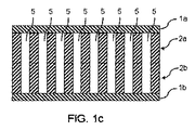
したがって、本発明によれば、次の工程を備える、電気機械の(例えば圧電気の)変換器の製造プロセスが提案されている。すなわち、当該製造プロセスは、
積層工程を除いて、印刷及び/又はコーティングのプロセスにより、第1の連続的なポリマー層(1; 1a)に対して穴(3; 3a)を有する第1のポリマー層(2; 2a)を付け加える(apply)工程A)と、
穴(3; 3a)を有する前記第1のポリマー層(2; 2a)の穴(3; 3a)が閉じられてボイド(void)(5)を形成するように、穴(3; 3a)を有する第1のポリマー層(2; 2a)に被覆(covering)(4; 1b、2b)を付け加える(apply)工程B)と、及び、
穴(3; 3a)を有する前記第1のポリマー層(2; 2a)に前記被覆(4; 1b、2b)を接合する工程C)と、を備え、
工程D)において、電極(6a)が第1の連続的なポリマー層(1、1a)の外側に付け加えられ、電極(6b)が被覆(4; 1b、2b)の外側に付け加えられて、当該電極(6a、6b)が、工程A)乃至工程C)の一つの工程の前後に、互いに独立してあるいは同時に付け加えられて、
工程E)において、工程C)の後に、あるいは工程C)に続く工程の後に得られた配置(arrangement)がチャージされる(charged)ことを特徴とする。
Therefore, according to the present invention, a manufacturing process of an electrical machine (for example piezoelectric) transducer is proposed comprising the following steps. That is, the manufacturing process is
The first polymer layer (2; 2a) having holes (3; 3a) with respect to the first continuous polymer layer (1; 1a) by a printing and / or coating process, excluding the laminating step. Apply step A);
The hole (3; 3a) is formed so that the hole (3; 3a) of the first polymer layer (2; 2a) having the hole (3; 3a) is closed to form a void (5). Applying a covering (4; 1b, 2b) to the first polymer layer (2; 2a) having step B); and
Bonding the coating (4; 1b, 2b) to the first polymer layer (2; 2a) having a hole (3; 3a),
In step D), the electrode (6a) is applied to the outside of the first continuous polymer layer (1, 1a) and the electrode (6b) is added to the outside of the coating (4; 1b, 2b) The electrodes (6a, 6b) are added independently or simultaneously with each other before and after one of the steps A) to C),
In step E), the arrangement obtained after step C) or after the step following step C) is charged.
本発明に係るプロセスにより、電気機械の変換器は、好適に大規模で製造される。 By means of the process according to the invention, the electrical machine converter is preferably manufactured on a large scale.
本発明の範囲内で、コーティングプロセスは、例えばゲルハードらの文献において開示されるように、積層工程でないこととして特に理解される。 Within the scope of the present invention, the coating process is specifically understood as not being a laminating step, as disclosed, for example, in Gelhard et al.
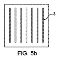
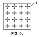
さらに、穴は、本発明に係るプロセスにおいて様々な形状を有することができる。したがって、穴の形状は、円形の断面領域を持った円筒形状に限定されない。さらに、本発明に係るプロセスは、異なった形状の穴を組み合わせる可能性を提供する。このように、一方では、もたらされたボイドのトータルボイド体積を最大にすることは好適には可能である。他方では、本発明に係るプロセスによって製造された電気機械の変換器の電気機械の(特に圧電気の)プロパティは、穴形状、配置及び/又は分布(distribution)の選択によって調節される。 Furthermore, the holes can have various shapes in the process according to the invention. Therefore, the shape of the hole is not limited to a cylindrical shape having a circular cross-sectional area. Furthermore, the process according to the invention offers the possibility of combining differently shaped holes. Thus, on the one hand, it is preferably possible to maximize the total void volume of the resulting voids. On the other hand, the electrical machine (especially piezoelectric) properties of the transducer of the electrical machine produced by the process according to the invention are adjusted by the choice of hole shape, arrangement and / or distribution.
さらに、バリ及び他の縁の鋭い(sharp-edged)穴表面の不規則性は、本発明に係るプロセスによって回避される。一方では、このことは、電気機械の、特に圧電気のプロパティ有利な効果がある。他方では、かかる不規則性を除去するという作業工程(working step)が不必要であるので、それは、変換器の製造における費用を低減する。 Furthermore, irregularities in burrs and other sharp-edged hole surfaces are avoided by the process according to the invention. On the one hand, this has the advantageous effect of the electrical machine, in particular the piezoelectric property. On the other hand, it reduces the cost in the production of the transducer, since the working step of removing such irregularities is unnecessary.
好適には、穴を有するポリマー層は、製造されることになっている電気機械の変換器をその厚みに沿ってより柔軟にすることができ、その弾性係数を低下させて、もたらされた(resulting)ボイドにおいて分極プロセスを可能にし、及び/又は帯電プロセスの後に連続的なポリマー層において形成された負荷(load)層を分離する。 Preferably, the polymer layer with the holes was made possible by making the electromechanical transducer to be manufactured more flexible along its thickness, reducing its elastic modulus. Enabling the polarization process in the voiding and / or separating the load layer formed in the continuous polymer layer after the charging process.
当該プロセスの実施態様において、被覆は、穴を有する第2のポリマー層と、第2の連続的なポリマー層と、を備える。穴を有する第2のポリマー層は、第2の連続的なポリマー層の上に配置されている。特に、被覆は、穴を有する第2のポリマー層と、第2の連続的なポリマー層と、から成ることができる。 In an embodiment of the process, the coating comprises a second polymer layer having holes and a second continuous polymer layer. A second polymer layer having holes is disposed over the second continuous polymer layer. In particular, the coating can consist of a second polymer layer with holes and a second continuous polymer layer.
当該プロセスの更なる実施態様において、被覆は第3の連続的なポリマー層である。 In a further embodiment of the process, the coating is a third continuous polymer layer.
当該プロセスの更なる実施態様において、被覆は、印刷プロセス及び/又はコーティングプロセスにより、第2の連続的なポリマー層に対して穴を有する第2のポリマー層を付け加えることにより製造される。 In a further embodiment of the process, the coating is produced by adding a second polymer layer having holes to the second continuous polymer layer by a printing process and / or a coating process.
第1の連続的なポリマー層に付け加えられた後の、穴を有する第1のポリマー層の材料は、例えば、部分的に乾燥され及び/又は部分的に架橋(crosslinked)され及び/又は部分的に固化され(solidified)及び/又は部分的に結晶されて、部分的に硬化される。同様に、第2の連続的なポリマー層に付け加えられた後の、穴を有する第2のポリマー層の材料は、例えば、部分的に乾燥され及び/又は部分的に架橋(crosslinked)され及び/又は部分的に固化され(solidified)及び/又は部分的に結晶されて、部分的に硬化される。特に、第1の連続的なポリマー層に付け加えられた後の、穴を有する第1のポリマー層の材料及び/又は第2の連続的なポリマー層に付け加えられた後の、穴を有する第2のポリマー層の材料は、連続的なポリマー層に付け加えられる際のその粘性と比較してその粘性が増加するように、例えば、部分的に乾燥され及び/又は部分的に架橋(crosslinked)され及び/又は部分的に固化され(solidified)及び/又は部分的に結晶されて、部分的に硬化される。このように、一方では、穴の寸法安定性が改善される。他方では、材料の更なる硬化、特に完全な硬化により、部分的な硬化だけが、第3の連続的なポリマー層あるいは穴を有する第2のポリマー層に対して穴を有する第1のポリマー層を接合する可能性を提供する。 The material of the first polymer layer with holes after being added to the first continuous polymer layer can be, for example, partially dried and / or partially crosslinked and / or partially Solidified and / or partially crystallized and partially cured. Similarly, the material of the second polymer layer with holes after being added to the second continuous polymer layer can be, for example, partially dried and / or partially crosslinked and / or Or partially solidified and / or partially crystallized and partially cured. In particular, the first polymer layer material with holes after being applied to the first continuous polymer layer and / or the second material with holes after being applied to the second continuous polymer layer. The material of the polymer layer is, for example, partially dried and / or partially cross-linked so that its viscosity increases as compared to its viscosity when added to a continuous polymer layer and // partially solidified and / or partly crystallized and partly cured. Thus, on the one hand, the dimensional stability of the hole is improved. On the other hand, due to the further curing of the material, in particular complete curing, only a partial curing has a first polymer layer with holes relative to a third continuous polymer layer or a second polymer layer with holes. Provides the possibility of joining.
したがって、当該プロセスの更なる実施態様において、穴を有する第1のポリマー層を被覆に接合することは、第1の連続的なポリマー層に付け加えられた後に穴を有する第1のポリマー層の材料だけを部分的に硬化すること、及び/又は第2の連続的なポリマー層に付け加えられた後に穴を有する第2のポリマー層の材料だけを部分的に硬化すること、及び、被覆が付け加えられた後に穴を有する第1のポリマー層の材料をさらに硬化する、特に完全に硬化すること、及び/又は、被覆が付け加えられた後に穴を有する第2のポリマー層の材料をさらに硬化する、特に完全に硬化することによって達成される。本願明細書では、硬化は、乾燥及び/又は架橋及び/又は固化及び/又は結晶化を意味するものとして理解される。 Thus, in a further embodiment of the process, joining the first polymer layer with holes to the coating comprises the material of the first polymer layer with holes after being added to the first continuous polymer layer. Only partially curing and / or partially curing only the material of the second polymer layer with holes after being applied to the second continuous polymer layer and the coating is applied Further curing the material of the first polymer layer with holes after it, in particular completely curing, and / or further curing of the material of the second polymer layer with holes after the coating has been applied, in particular This is achieved by complete curing. As used herein, curing is understood as meaning drying and / or crosslinking and / or solidification and / or crystallization.
例えば、第1の連続的なポリマー層に付け加えられた後に穴を有する第1のポリマー層の材料を、及び/又は、第2の連続的なポリマー層に付け加えられた後に穴を有する第2のポリマー層の材料を、乾燥すること、例えば、熱的に乾燥することが可能であり、被覆が付け加えられた後だけに架橋を実行ことが可能である。 For example, a first polymer layer material having holes after being applied to the first continuous polymer layer and / or a second material having holes after being applied to the second continuous polymer layer. The material of the polymer layer can be dried, for example thermally dried, and crosslinking can be performed only after the coating has been applied.
さらなる実施例は、穴を有する第1のポリマー層及び/又は穴を有する第2のポリマー層として、固化する及び/又は無定形に結晶化する材料を、特にポリマー(例えばポリウレタン)を用いることである。固化する及び/又は無定形に結晶化する材料は、穴を有する第1の又は第2のポリマー層を形成するために、例えば、第1の又は第2の連続的なポリマー層への分散(dispersion)の形で付け加えることができる。固化する及び/又は無定形に結晶化する材料は、例えば、第1の又は第2の連続的なポリマー層に付け加えられる後に、部分的に固化する及び/又は無定形に結晶化することができ、被覆が付け加えられた後、完全に無定形に固化する及び/又は結晶化することができて、その結果として、穴を有する第1のポリマー層を被覆に接合することができる。しかしながら、固化する及び/又は無定形に結晶化する材料は、第1の又は第2の連続的なポリマー層に付け加えられた後に完全に固化する及び/又は無定形に結晶するとともに、被覆が付け加えられた後に架橋することができる。穴を有する第1のポリマー層は被覆に接合される。さらに、無定形に固化する及び/又は結晶する材料は、第1の又は第2の連続的なポリマー層に付け加えられた後に完全に固化する及び/又は無定形に結晶化することができ、被覆が付け加えられた後に、固化する及び/又は結晶化する材料が無定形に軟化する及び/又は溶融する温度に加熱することができ、第3の連続的なポリマー層、あるいは穴を有する別のポリマー層が濡れていて、穴を有するポリマー層の構造が保持されて、そして、低い温度まで冷却した後に、穴を有する第1のポリマー層は被覆に接合される。 A further example is to use a solidifying and / or amorphous crystallizing material, in particular a polymer (eg polyurethane), as the first polymer layer with holes and / or the second polymer layer with holes. is there. The material that solidifies and / or crystallizes amorphously may be dispersed, for example, in the first or second continuous polymer layer to form a first or second polymer layer with holes ( dispersion). The material that solidifies and / or amorphously crystallizes can be partially solidified and / or amorphously crystallized, for example, after being added to the first or second continuous polymer layer. After the coating has been applied, it can solidify and / or crystallize completely amorphous, so that a first polymer layer with holes can be joined to the coating. However, the material that solidifies and / or amorphously crystallizes after it is added to the first or second continuous polymer layer and then solidifies completely and / or crystallizes amorphously, with the addition of a coating. Can be crosslinked. A first polymer layer having holes is bonded to the coating. Furthermore, the amorphous solidifying and / or crystallizing material can be fully solidified and / or amorphously crystallized after being added to the first or second continuous polymer layer, Can be heated to a temperature at which the solidifying and / or crystallizing material softens and / or melts amorphously, a third continuous polymer layer, or another polymer with holes After the layer is wet and the structure of the polymer layer with holes is retained, and after cooling to a low temperature, the first polymer layer with holes is bonded to the coating.
穴を有する第1の及び/又は第2のポリマー層の材料は、例えば熱的に、紫外線光の照射(放射)により、赤外線光の照射により及び/又は乾燥により、架橋することができる。特に、層が、ポリカーボネートのような低いUV安定性を有するポリマーを備えるときには、架橋は、熱的に、赤外線の照射により、あるいは乾燥により、起こることができる。 The material of the first and / or second polymer layer with holes can be crosslinked, for example thermally, by irradiation with ultraviolet light (radiation), by irradiation with infrared light and / or by drying. In particular, when the layer comprises a polymer with low UV stability, such as polycarbonate, crosslinking can occur thermally, by infrared irradiation, or by drying.
当該プロセスの更なる実施態様において、穴を有する第1のポリマー層の取り付け及び/又は穴を有する第2のポリマー層の取り付けは、次のようなコーティング又は印刷工程によって起こる。すなわち、ドクターブレードによる塗布、スピンコーティング、浸せきコーティング、スプレーコーティング、カーテンコーティング(curtain coating)、スロットダイ(slot-die)コーティング、フレキソ印刷、グラビア印刷、タンポン印刷(tampon printing)、ディジタル印刷、熱転写印刷、多孔性印刷、特に、凸版印刷、平版印刷、オフセット印刷及び/又はスクリーン印刷、及び/又は例えばローラー・アプリケータをハルドエンジニアリング株式会社(Hardo Maschinenbau GmbH)(Bad Salzuflen、Germany)からのホットメルト接着剤に用いるローラー塗布工程、である。 In a further embodiment of the process, the attachment of the first polymer layer with holes and / or the attachment of the second polymer layer with holes occurs by a coating or printing process as follows. That is, application by doctor blade, spin coating, dip coating, spray coating, curtain coating, slot-die coating, flexographic printing, gravure printing, tampon printing, digital printing, thermal transfer printing Porous printing, in particular letterpress printing, lithographic printing, offset printing and / or screen printing, and / or hot-melt bonding of eg roller applicators from Hardo Maschinenbau GmbH (Bad Salzuflen, Germany) It is the roller application | coating process used for an agent.
穴を有する第1のポリマー層の塗布及び/又は穴を有する第2のポリマー層の塗布は、例えば、ドクターブレード、スピンコーティング、浸せきコーティング、スプレーコーティング及び/又はマトリックス又はテンプレートと併用されるカーテンコーティングによる塗布によって、実行される。 Application of the first polymer layer with holes and / or application of the second polymer layer with holes can be performed, for example, by doctor blade, spin coating, dip coating, spray coating and / or curtain coating in combination with a matrix or template It is executed by application by.
当該プロセスの更なる実施態様において、穴を有する第1のポリマー層の塗布及び/又は穴を有する第2のポリマー層の塗布は、スクリーン印刷プロセスによって実行される。 In a further embodiment of the process, the application of the first polymer layer with holes and / or the application of the second polymer layer with holes is performed by a screen printing process.
穴を有する第1のポリマー層の塗布及び/又は穴を有する第2のポリマー層の塗布は、加熱された、例えば電気的に加熱された、スクリーンを、特にスクリーン印刷織物を用いて実行される。スクリーン印刷用の加熱されたスクリーンは、例えば、商標名がホットスクリーンであるケーネン株式会社(Koenen GmbH)(Ottobrunn、Germany)によって供給される。 The application of the first polymer layer with holes and / or the application of the second polymer layer with holes is carried out using a heated, for example electrically heated, screen, in particular using a screen-printed fabric. . A heated screen for screen printing is supplied, for example, by Koenen GmbH (Ottobrunn, Germany) under the trade name Hot Screen.
加熱されたスクリーンに対するスクリーン印刷ペーストとして、例えば、ポリウレタン、ポリエステル及び/又はポリアミドに基づく(based on)反応性及び非反応性のホットメルト接着剤のような熱可塑性物質、特に、ホットメルト・ペースト、あるいは高沸点溶媒を含む及び/又は紫外線光の下で乾燥するスクリーン印刷ペーストを用いることができる。 As screen printing pastes for heated screens, for example, thermoplastics such as reactive and non-reactive hot melt adhesives based on polyurethane, polyester and / or polyamide, in particular hot melt pastes, Alternatively, a screen printing paste containing a high boiling point solvent and / or drying under ultraviolet light can be used.
熱可塑性物質(すなわちホットメルト・ペースト)は、室温で固体であることが好適である。例えば60℃以上乃至80℃以下のスクリーンが加熱される温度で、従来のスクリーン印刷ペーストの粘性と比較可能な粘性が、例えば1000mPa・s以上乃至20,000mPa・s以下に達する。溶媒の追加は、かかるホットメルト・ペーストでは必要としない。熱可塑性物質は連続的なポリマー層との接触で冷えて、鋭い輪郭を維持することができる。鋭い輪郭の構造に付け加えて、加熱されたスクリーン及び熱可塑性物質の使用は、乾燥工程を省略できるという利点を有する。 The thermoplastic (i.e. hot melt paste) is preferably solid at room temperature. For example, at a temperature at which a screen of 60 ° C. to 80 ° C. is heated, the viscosity comparable to that of a conventional screen printing paste reaches, for example, 1000 mPa · s to 20,000 mPa · s. The addition of solvent is not required with such hot melt pastes. The thermoplastic can cool upon contact with the continuous polymer layer and maintain a sharp profile. In addition to the sharp contoured structure, the use of a heated screen and thermoplastic material has the advantage that the drying process can be omitted.
高沸点溶媒を備える及び/又は紫外線光下で乾燥するスクリーン印刷ペーストは、加熱されたスクリーン、特にスクリーン印刷織物を用いて、及び選択的に加熱されたドクターブレードを用いて、塗布することができる。スクリーンの加熱は、ペーストの粘性を低下させる。ペーストが連続的なポリマー層と接触するとき、ペーストが冷えてその粘性が増加する。このことは、輪郭鮮鋭度が増加するという利点を有する。スクリーン印刷織物の繊度(fineness)に応じて、低粘度ペーストも選択的に用いることができる。織物の繊度は、センチメートル当たりのスレッド(thread)の数を意味するものとして理解される。例えば、センチメートル当たり少なくとも120スレッド・カウント、特にセンチメートル当たり少なくとも150スレッド・カウントを有するスクリーン印刷織物が用いられる。 Screen printing pastes with high-boiling solvents and / or drying under UV light can be applied using heated screens, especially screen-printed fabrics, and selectively using a heated doctor blade. . Heating the screen reduces the viscosity of the paste. When the paste comes into contact with the continuous polymer layer, the paste cools and its viscosity increases. This has the advantage that the contour sharpness is increased. Depending on the fineness of the screen printed fabric, low viscosity pastes can also be used selectively. The fineness of a fabric is understood as meaning the number of threads per centimeter. For example, screen printed fabrics having at least 120 thread counts per centimeter, in particular at least 150 thread counts per centimeter, are used.
加熱されたスクリーンが用いられるたときに、ペーストが印刷時に冷えることを防止するために、及び、印刷の間に最適な加工性を実現するために、印刷のブレード及び/又はフラッドコーター(flood coater)を加熱することができる。 Printing blades and / or flood coaters to prevent the paste from cooling down during printing when a heated screen is used and to achieve optimum workability during printing ) Can be heated.
穴を有するポリマー層の厚みを増加させるために、複数の印刷が上下に(one above the other)実施される。穴を有する第1の又は第2のポリマー層の材料は、個々の印刷工程の間に、例えば乾燥される及び/又は架橋される及び/又は固化される及び/又は結晶化されるように、部分的にあるいは完全に硬化される。当該印刷は、選択的にウェット・オン・ウェット(wet-on-wet)で実施される。 In order to increase the thickness of the polymer layer with holes, multiple printings are performed one above the other. The material of the first or second polymer layer with holes can be, for example, dried and / or crosslinked and / or solidified and / or crystallized during the individual printing steps. Partially or completely cured. The printing is optionally performed wet-on-wet.
穴を有するポリマー層の構造を印刷プロセスによって直接に塗布することができるが、上記被覆プロセスにおける後者の穴の位置は、当初はカバーされるか覆われる。 Although the structure of the polymer layer with holes can be applied directly by a printing process, the position of the latter holes in the coating process is initially covered or covered.
当該プロセスの更なる実施態様において、穴を有する第1のポリマー層の取り付け及び/又は穴を有する第2のポリマー層の取り付けは、転写コーティングによって実行される。「転写コーティング」とは、穴を有するポリマー層が、印刷プロセス及び/又はコーティングプロセスにより転写層(例えば剥離(release)紙又は剥離フィルム)の上に最初に形成されて、連続的なポリマー層に転写され、連続的なポリマー層に接合されることを特に意味することとして理解される。適切な印刷プロセス及び/又はコーティングプロセスは、前述の印刷プロセス及び/又はコーティングプロセスである。例えば、最初は部分的にだけ硬化してそしてその後さらに特に十分に硬化する工程及び前述の積層工程に基づいた前述の手順が、連続的なポリマー層に接合するのに適切である。好適には、転写コーティングは、穴を有する第1の及び/又は第2のポリマー層の製造を空間的に一時的に分離すること、及び穴を有する層を連続層に接合することの可能性を提供する。 In a further embodiment of the process, the attachment of the first polymer layer with holes and / or the attachment of the second polymer layer with holes is performed by transfer coating. “Transfer coating” means that a polymer layer with holes is first formed on a transfer layer (eg, release paper or release film) by a printing and / or coating process into a continuous polymer layer. It is understood to mean in particular that it is transferred and joined to a continuous polymer layer. Suitable printing processes and / or coating processes are the printing processes and / or coating processes described above. For example, the above-described procedure based on a process that initially only partially cures and then more particularly fully cures and the above-described lamination process is suitable for joining continuous polymer layers. Preferably, the transfer coating spatially temporarily separates the production of the first and / or second polymer layer with holes and the possibility of joining the layer with holes to the continuous layer. I will provide a.
当該プロセスの更なる実施態様において、穴を有する第1のポリマー層の穴は、穴を有する第1のポリマー層を、特に連続的なポリマー層の方向に貫通し(pass right through)、及び/又は、穴を有する第2のポリマー層の穴は、穴を有する第2のポリマー層を、特に連続的なポリマー層の方向に貫通する(pass right through)。このように、本発明に係るプロセスの完成時に形成されたボイド(void)は、一方の側で1つの(第1の)連続的なポリマー層と接触し、他方の側で(第2の又は第3の)連続的なポリマー層と接触する。このことは、結果として(in turn)、製造される電気機械のエネルギー変換器の電気機械の挙動に有利な効果を有する。 In a further embodiment of the process, the holes in the first polymer layer with holes pass through the first polymer layer with holes, in particular in the direction of the continuous polymer layer, and / or Alternatively, the holes in the second polymer layer with holes pass through the second polymer layer with holes, especially in the direction of the continuous polymer layer. Thus, the voids formed at the completion of the process according to the invention are in contact with one (first) continuous polymer layer on one side and on the other side (second or Contact with a third) continuous polymer layer. This has an advantageous effect on the electrical machine behavior of the energy converter of the electrical machine to be produced as a result.
本発明の範囲内に、穴を有する第1の及び/又は第2のポリマー層は、第1の又は第2の連続的なポリマー層を穴を有する連続的なポリマー層で印刷すること及び/又はコーティングすることにより、あるいは、第1の又は第2の連続的なポリマー層を同一又は異なった、分離又は相互接続された構造で印刷すること及び/又はコーティングすることにより形成される。前述の構造は、例えば、幾何学的図形の曲線又は直線、独立線(individual line)又は交差線又は円周線、断面(cross)の円形線又は円周線のような、点又は線のような小さな表面領域を持っているか、又は、満たされた(filled)長方形、円、クロスなどのような大きな表面領域を持っている。好適には、当該構造のサイズと層厚みは、連続的なポリマー層が互いに接触できない及び/又は製造後に得られたトータルのボイドの体積ができるだけ大きいように構成されている。電気機械変換器において、穴を有する第1のポリマー層及び/又は第2のポリマー層は、例えば、1μm以上乃至800μm以下の層厚みを、特に10μm以上乃至400μm以下の層厚みをそれぞれ有することができる。もし、穴を有する第1のポリマー層だけが電気機械変換器の製造の間に付け加えられるならば、電気機械変換器における穴を有する第1のポリマー層は、特に1μm以上乃至800μm以下の層厚みを、例えば10μm以上乃至400μm以下の層厚みを有することができる。もし穴を有する第1のポリマー層及び第2のポリマー層の両方が電気機械変換器の製造の間に付け加えられるならば、電気機械変換器における穴を有する第1のポリマー層及び第2のポリマー層は、1μm以上乃至800μm以下の全体層厚みを、例えば10μm以上乃至400μm以下の全体層厚みを有することができる。電気機械変換器の製造の中で用いられる印刷プロセス及び/又はコーティングプロセス、及びパラメータに依存して、例えば溶媒含有印刷インキ、インキ、ペースト、製剤(formulation)、ラッカーあるいは接着剤を用いたときに、穴を有するポリマー層を連続層に塗布した直後での穴を有する第1のポリマー層及び/又は第2のポリマー層の層厚みが、電気機械変換器における穴を有するもたらされた(resulting)ポリマー層の層厚みよりも大きいか著しく大きいことが可能である。好適には、レイアウト、印刷プロセスパラメータ及び/又はコーティングプロセス・パラメータは、穴を有するポリマー層が、連続的なポリマー層に接触していない、ボイドを有さないように特にガス介在物を有さないように、構成されている。 Within the scope of the present invention, the first and / or second polymer layer with holes prints the first or second continuous polymer layer with a continuous polymer layer with holes and / or Or by coating, or by printing and / or coating the first or second continuous polymer layer with the same or different, separated or interconnected structures. Such a structure can be, for example, a point or a line, such as a curve or straight line of a geometric figure, an individual line or cross line or circumference, a circular line or circumference of a cross. Have a small surface area or a large surface area such as filled rectangles, circles, crosses, etc. Preferably, the size and layer thickness of the structure are configured so that the continuous polymer layers cannot contact each other and / or the total void volume obtained after production is as large as possible. In the electromechanical transducer, the first polymer layer and / or the second polymer layer having holes may have a layer thickness of 1 μm to 800 μm, particularly 10 μm to 400 μm, respectively. it can. If only the first polymer layer with holes is added during the manufacture of the electromechanical transducer, the first polymer layer with holes in the electromechanical transducer has a layer thickness of not less than 1 μm and not more than 800 μm, in particular. Can have a layer thickness of 10 μm to 400 μm, for example. If both the first polymer layer and the second polymer layer having holes are added during manufacture of the electromechanical transducer, the first polymer layer and the second polymer having holes in the electromechanical transducer The layer may have a total layer thickness of 1 μm to 800 μm, for example, a total layer thickness of 10 μm to 400 μm. Depending on the printing and / or coating process and parameters used in the manufacture of the electromechanical transducer, for example when using solvent-containing printing inks, inks, pastes, formulations, lacquers or adhesives The layer thickness of the first polymer layer and / or the second polymer layer with holes immediately after applying the polymer layer with holes to the continuous layer resulted in having holes in the electromechanical transducer. ) It can be greater or significantly greater than the layer thickness of the polymer layer. Preferably, the layout, printing process parameters and / or coating process parameters have gas inclusions in particular such that the polymer layer with holes is not in contact with the continuous polymer layer and has no voids. Is configured so that there is no.
被覆が付け加えられたとき、穴を有する第1のポリマー層の穴の少なくともいくつか、及び穴を有する第2のポリマー層の穴の少なくともいくつかが、部分的にあるいは完全に重なるように、穴を有する第1のポリマー層の穴と、穴を有する第2のポリマー層の穴とが、形成且つ配置される。 The hole is such that when the coating is applied, at least some of the holes in the first polymer layer having holes and at least some of the holes in the second polymer layer having holes partially or completely overlap. And holes in the first polymer layer having holes and holes in the second polymer layer having holes are formed and arranged.
当該プロセスの更なる実施態様において、被覆が付け加えられたとき、穴を有する第1のポリマー層の1つの穴、及び穴を有する第2のポリマー層の1つの穴が、部分的にあるいは完全に重なるように、穴を有する第1のポリマー層の穴と、穴を有する第2のポリマー層の穴とが、形成且つ配置される。このことは、被覆が付け加えられたとき、穴を有する第1のポリマー層の1つの穴、及び穴を有する第2のポリマー層の1つの穴が、共通のボイドを形成するように、好適には、穴を有する第1のポリマー層の穴と、穴を有する第2のポリマー層の穴とが、形成且つ配置されることを意味する。穴を有する第1のポリマー層の1つの穴、及び穴を有する第2のポリマー層の1つの穴が、完全に重なるように、好適には、穴を有する第1のポリマー層の穴と、穴を有する第2のポリマー層の穴とが、形成且つ配置される。例えば、穴を有する第1の及び第2のポリマー層は、合同である(congruent)、特に同一である。一方の側にある連続的なポリマー層から他方の側の連続的なポリマー層まで連続的であるボイドを製造することがこのように可能である。 In a further embodiment of the process, when the coating is applied, one hole in the first polymer layer having holes and one hole in the second polymer layer having holes may be partially or completely. A hole in the first polymer layer having holes and a hole in the second polymer layer having holes are formed and arranged to overlap. This is preferably such that when the coating is applied, one hole in the first polymer layer with holes and one hole in the second polymer layer with holes form a common void. Means that the holes of the first polymer layer having holes and the holes of the second polymer layer having holes are formed and arranged. Preferably, the holes in the first polymer layer having holes so that one hole in the first polymer layer having holes and one hole in the second polymer layer having holes completely overlap; A hole in the second polymer layer having a hole is formed and arranged. For example, the first and second polymer layers with holes are congruent, in particular identical. It is thus possible to produce voids that are continuous from a continuous polymer layer on one side to a continuous polymer layer on the other side.
本発明の範囲内で、少なくとも穴を有する第1のポリマー層の穴の少なくともいくつか及び/又は穴を有する第2のポリマー層の穴の少なくともいくつかは、大略丸い物(例えば円形、楕円、楕円形)、多角形(例えば三角形、長方形、台形、菱形、五角形、六角形、特にハニカム形状)、十字形、星形、部分的に丸くて部分的に多角形(例えばS字形状)等の断面領域からなるグループから選ばれた断面領域を有する形状を有することができる。しかしながら、少なくとも穴を有する第1のポリマー層の穴の全て及び/又は穴を有する第2のポリマー層の穴の全ては、大略丸い物(例えば円形、楕円、楕円形)、多角形(例えば三角形、長方形、台形、菱形、五角形、六角形、特にハニカム形状)、十字形、星形、部分的に丸くて部分的に多角形(例えばS字形状)、それらから異なる形状等の断面領域からなるグループから選ばれた断面領域を有する形状を有することも可能である。 Within the scope of the present invention, at least some of the holes in the first polymer layer having at least holes and / or at least some of the holes in the second polymer layer having holes are generally rounded (eg, circular, oval, Oval), polygons (eg, triangles, rectangles, trapezoids, rhombuses, pentagons, hexagons, especially honeycomb shapes), crosses, stars, partially rounded and partially polygonal (eg S-shaped), etc. It may have a shape having a cross-sectional area selected from the group consisting of cross-sectional areas. However, at least all of the holes of the first polymer layer with holes and / or all of the holes of the second polymer layer with holes are generally rounded (eg circular, oval, elliptical), polygonal (eg triangular) , Rectangles, trapezoids, rhombuses, pentagons, hexagons, especially honeycomb shapes), cross shapes, star shapes, partially rounded and partially polygonal (for example, S-shaped), and different cross-sectional areas. It is also possible to have a shape with a cross-sectional area selected from a group.
当該プロセスの更なる実施態様の範囲内で、穴を有する第1のポリマー層の穴及び/又は穴を有する第2のポリマー層の穴は、ハニカム形状に形成され及び/又は配置される。穴のハニカムの形状及び配置は、一方で、非常に大きなトータルのボイド積に帰着する。他方で、穴のハニカムの形状及び配置は、高い機械的安定性を有することができる。 Within the scope of further embodiments of the process, the holes of the first polymer layer with holes and / or the holes of the second polymer layer with holes are formed and / or arranged in a honeycomb shape. The shape and arrangement of the honeycomb in the hole, on the other hand, results in a very large total void volume. On the other hand, the shape and arrangement of the honeycomb of the holes can have a high mechanical stability.
断面領域のサイズは、穴を有するポリマー層の穴の全てにおいて、異なるか又は同じとすることができる。 The size of the cross-sectional area can be different or the same in all the holes of the polymer layer with holes.
本発明に係るプロセスの範囲内で、穴を有する第1の及び/又は第2のポリマー層の穴は、均一に又は不均一に分布することができる。特に、穴を有する第1の及び/又は第2のポリマー層の穴は、均一に分布することができる。しかしながら、製造されることになっている電気機械変換器の適用分野に依存して、穴を有する第1の及び/又は第2のポリマー層の穴を、特に意図的に、空間分解された(space-resolved)方法で不均一に分布することも好適である。 Within the scope of the process according to the invention, the holes of the first and / or second polymer layer with holes can be distributed uniformly or non-uniformly. In particular, the holes of the first and / or second polymer layer with holes can be evenly distributed. However, depending on the field of application of the electromechanical transducer to be manufactured, the holes of the first and / or second polymer layer with holes have been spatially resolved, especially intentionally ( A non-uniform distribution by a space-resolved method is also suitable.
選択的に、穴を有する第1の及び/又は第2のポリマー層の穴は、部分的にあるいは完全に相互接合される。 Optionally, the holes in the first and / or second polymer layer with holes are partially or fully interconnected.
当該プロセスの更なる実施態様において、穴を有する第1のポリマー層及び/又は穴を有する第2のポリマー層は、異なった形状の穴を備える。特に、穴を有する第1の及び/又は第2のポリマー層は、第1の形状の複数の穴と、第2の形状の複数の穴と、選択的に第3形状の複数の穴等とを有する。穴を有する第1の又は第2のポリマー層における異なった形状の穴は、均一にあるいは不均一に分布することができ、及び/又は部分的にあるいは完全に相互接合される。一方、好適には、もたらされた(resulting)ボイドのトータルボイド体積は、異なった形状の穴の組み合わせにより最大にすることができる。他方、本発明に係るプロセスによって製造された電気機械の変換器電気機械の特性、特に圧電気の特性は、穴の形状、配置及び/又は分布の選択によって調節される。 In a further embodiment of the process, the first polymer layer with holes and / or the second polymer layer with holes comprises holes of different shapes. In particular, the first and / or second polymer layer having holes includes a plurality of holes in a first shape, a plurality of holes in a second shape, a plurality of holes in a third shape selectively, and the like. Have Differently shaped holes in the first or second polymer layer with holes can be uniformly or non-uniformly distributed and / or partially or fully interconnected. On the other hand, preferably the total void volume of the resulting voids can be maximized by a combination of differently shaped holes. On the other hand, the properties of the electrical machine of the electrical machine produced by the process according to the invention, in particular the properties of the piezoelectric, are adjusted by the choice of the hole shape, arrangement and / or distribution.
特に、穴を有する第1の及び/又は第2の層の穴の少なくともいくつかは、円形の断面領域、特に、略円形の断面領域を有さない形状を有することができる。この理由は、単独で含む円形又は略円形の断面領域を有するボイドだけを備える層のトータルボイド体積が、例えば、円形及び菱形の断面領域を有するボイド均一に分布された配置における、あるいはハニカム断面領域を有するボイドだけに基づく配置における、トータルのボイド体積より小さいことである。 In particular, at least some of the holes in the first and / or second layer with holes can have a circular cross-sectional area, in particular a shape without a substantially circular cross-sectional area. The reason for this is that the total void volume of the layer comprising only the voids having a circular or substantially circular cross-sectional area alone, for example, in an arrangement in which the voids having circular and rhombic cross-sectional areas are uniformly distributed, or in the honeycomb cross-sectional area Less than the total void volume in an arrangement based solely on voids having
穴を有する第1の及び第2のポリマー層は、ボイドにおける分極プロセスを可能にするとともに、帯電(charging)プロセスの後にポリマーフィルムに形成された帯電(charge)層を分離するのに適しているあらゆるポリマーから互いに無関係に原則としては形成される。例えば、穴を有するポリマー層は、エラストマーから形成される。 The first and second polymer layers with holes allow a polarization process in the voids and are suitable for separating the charge layer formed in the polymer film after the charging process. In principle, it is formed from any polymer independently of each other. For example, the polymer layer having holes is formed from an elastomer.
印刷インキ、インキ、ペースト、製剤(formulation)、ラッカーあるいは接着剤は、穴を有する第1の及び/又は第2のポリマー層を塗布する(付け加える)ために、あるいは、穴を有する第1の及び/又は第2のポリマー層を形成するために、用いることができる。これらは、プロセスの直前に調合(formulated)されるか、あるいは市販されている。 Printing inks, inks, pastes, formulations, lacquers or adhesives are used to apply (append) the first and / or second polymer layer with holes, or with the first and It can be used to form a second polymer layer. These are either formulated just before the process or are commercially available.
例えば、印刷インキ、インキ、ペースト、製剤(formulation)、ラッカー、接着剤、あるいは穴を有する第1の及び/又は第2のポリマー層は、セルロースエステル、セルロースエーテル、ゴム誘導体、ポリエステル樹脂、不飽和ポリエステル、アルキド樹脂、フェノール樹脂、アミノ樹脂、アミド樹脂、ケトン樹脂、キシレン-ホルムアルデヒド樹脂、エポキシ樹脂、フェノキシ樹脂、ポリオレフィン、ポリ塩化ビニル、ポリビニルエステル、ポリビニルアルコール、ポリビニルアセタール、ポリビニルエーテル、ポリアクリレート(polyacrylates)、ポリメタクリレート(polymethacrylates)、ポリスチレン、ポリカーボネート、ポリエステル、コポリエステル、ポリアミド、シリコーン樹脂、ポリウレタン(polyurethanes)、特にポリウレタン(polyurethanes)、及びこれらのポリマーの混合物、特にバインダーの形での混合物から成るグループから選ばれた少なくとも1つのポリマーを含むか、あるいはこれらから形成される。印刷インキ、インキ、ペースト、製剤(formulation)、ラッカーあるいは接着剤、あるいは穴を有する第1の及び/又は第2のポリマー層が樹脂を備えるならば、印刷インキ、インキ、ペースト、製剤(formulation)、ラッカーあるいは接着剤、あるいは穴を有する第1の及び/又は第2のポリマー層は、選択的に、1つ以上の樹脂硬化剤をさらに備えることができる。 For example, printing inks, inks, pastes, formulations, lacquers, adhesives, or first and / or second polymer layers with holes may be cellulose esters, cellulose ethers, rubber derivatives, polyester resins, unsaturated Polyester, alkyd resin, phenol resin, amino resin, amide resin, ketone resin, xylene-formaldehyde resin, epoxy resin, phenoxy resin, polyolefin, polyvinyl chloride, polyvinyl ester, polyvinyl alcohol, polyvinyl acetal, polyvinyl ether, polyacrylates ), Polymethacrylates, polystyrene, polycarbonate, polyester, copolyester, polyamide, silicone resin, polyurethanes, especially polyurethane anes), and a mixture of these polymers, in particular at least one polymer selected from the group consisting of a mixture in the form of a binder. Printing inks, inks, pastes, formulations, lacquers or adhesives, or printing inks, inks, pastes, formulations if the first and / or second polymer layer with holes comprises a resin The first and / or second polymer layer with lacquers or adhesives or holes can optionally further comprise one or more resin hardeners.
多くの市販されている製品は、特に結合剤として、印刷インキ、インキ、ペースト、製剤(formulation)、ラッカーあるいは接着剤、あるいは穴を有する第1の及び/又は第2のポリマー層にさらに適切である。当該製品は、例えば、ドイツ国のバイエルンにあるProll KG、WeissenburgによるNoriphan HTR、Noriphan PCI、Noriphan N2K、Noricry及びNoriPETという商品名(trade name)で、ドイツ国のタムにあるMarabu GmbH社によるMaraflex FXという商品名で、ドイツ国のボトロップにあるFujifilm Sericol Deutschland GmbHによるPolyplast PYという商品名で、ドイツ国のヌーレンベルグにあるCoates Screen Inks GmbHによるスクリーン印刷インキ、HG、SG、CP、CX、PK、J、TL、及びYNという商品名で、米国のシャウニーにあるNazdarによる1500 Series UV Flexiform、1600 Power Print Series、1700 Versa Print, 3200 Series、1800 Power Print plus、9700 Series, PP Series、7200 Lacquer及び7900 Seriesという商品名で、市販されている。 Many commercially available products are more suitable for first and / or second polymer layers with printing inks, inks, pastes, formulations, lacquers or adhesives, or holes, especially as binders. is there. The products are, for example, Proll KG in Bavaria, Germany, Noriphan HTR by Weissenburg, Noriphan PCI, Noriphan N2K, Norricry and NoriPET under the trade name, Maraflex FX by Marabu GmbH in Tam, Germany The product name is Polyplast PY by Fujifilm Sericol Deutschland GmbH in Bottrop, Germany, and the screen printing ink, HG, SG, CP, CX, PK, J, by Coates Screen Inks GmbH in Nuremberg, Germany. Under the trade names TL and YN, the 1500 Series UV Flexiform, 1600 Power Print Series, 1700 Versa Print, 3200 Series, 1800 Power Print plus, 9700 Series, PP Series, 7200 Lacquer and 7900 Series by Nazdar in Shawnee, USA It is commercially available under the trade name.
紫外線光の下で硬化する印刷インキ、インキ、ペースト、製剤(formulation)、ラッカーあるいは接着剤に適切なものとして、特に結合剤として、例えばエポキシ樹脂、エステル、エーテル及び/又はウレタンアクリレートがある。ウレタンアクリレートは、反応性希釈剤(低粘度のメタ/アクリル酸エステル(meth/acrylic acid esters))における溶液(solution)の形態で、低粘度オリゴマーの形態で、粉体コーティング技術に対する固体の形態で、あるいはウレタンアクリレート分散の形態で用いられる。ウレタンアクリレートは、ドイツ国のレーバークーゼンにあるバイエルマテリアルサイエンス社からのDesmoluxという商品名/商標で、入手可能である。硬化に適切なものとして、例えば、電子ビーム硬化、モノ硬化技術及びデュアル硬化技術がある。イソシアネートウレタンアクリル(Isocyanatourethane acryls)は、デュアル硬化技術に特に適している。 Suitable for printing inks, inks, pastes, formulations, lacquers or adhesives that cure under UV light, in particular as binders, for example epoxy resins, esters, ethers and / or urethane acrylates. Urethane acrylates are in the form of solutions in reactive diluents (low viscosity meth / acrylic acid esters), in the form of low viscosity oligomers, in the form of solids for powder coating technology Or in the form of urethane acrylate dispersion. Urethane acrylates are available under the trade name / trademark Desmolux from Bayer MaterialScience, Leverkusen, Germany. Suitable for curing are, for example, electron beam curing, mono-curing technology and dual curing technology. Isocyanatourethane acryls are particularly suitable for dual curing techniques.
印刷インキ、インキ、ペースト、製剤(formulation)、ラッカーあるいは接着剤は、水性の、あるいは水以外の溶媒に基づくことができる。 Printing inks, inks, pastes, formulations, lacquers or adhesives can be based on aqueous or non-water solvents.
印刷インキ、インキ、ペースト、製剤(formulation)、ラッカー又は接着剤、あるいは穴を有する第1の及び/又は第2のポリマー層は、1つ以上のポリウレタン(polyurethanes)を備えるか、1つ以上のポリウレタン(polyurethanes)から形成される。特に、印刷インキ、インキ、ペースト、製剤(formulation)、ラッカーあるいは接着剤、あるいは穴を有する第1の及び/又は第2のポリマー層は、1つ以上の一液形の(one-component)ポリウレタン及び/又は1つ以上の二液形の(two-component)ポリウレタン及び/又は1つ以上の水性ポリウレタン分散液(aqueous polyurethane dispersions)及び/又は1つ以上のポリウレタンホットメルト接着剤を備えるか、又はそれらから形成される。 The printing ink, ink, paste, formulation, lacquer or adhesive, or first and / or second polymer layer with holes comprises one or more polyurethanes or one or more Formed from polyurethanes. In particular, the first and / or second polymer layer with printing inks, inks, pastes, formulations, lacquers or adhesives, or holes may be one or more one-component polyurethanes. And / or comprises one or more two-component polyurethanes and / or one or more aqueous polyurethane dispersions and / or one or more polyurethane hot melt adhesives, or Formed from them.
例えば、印刷インキ、インキ、ペースト、製剤(formulation)、ラッカー、接着剤、あるいは穴を有する第1の及び/又は第2のポリマー層は、2より大きくて4までの平均の官能基(mean functionality)を有する多官能イソシアネート(polyfunctional isocyanates)の化学量論的過剰量とアルコールとの反応によって製造されるプレポリマーを備える1つ以上の一液形のポリウレタンを備えるか、あるいはそれらから形成される。当該プレポリマーは、選択的に添加剤及び/又は溶媒をさらに備えることができる。 For example, first and / or second polymer layers having printing inks, inks, pastes, formulations, lacquers, adhesives, or holes may have an average functionality greater than 2 and up to 4. And / or one or more one-part polyurethanes comprising a prepolymer prepared by reaction of a stoichiometric excess of polyfunctional isocyanates with alcohol and alcohol. The prepolymer can optionally further comprise additives and / or solvents.
プレポリマーは、ウレタン基及び末端イソシアネート基(terminal isocyanate groups)を形成するために、例えば、平均して単官能基のアルコールとポリオールとの混合物であるアルコールとポリウレタンとの反応によって得られる。 The prepolymer is obtained, for example, by reaction of an alcohol with a polyurethane, which on average is a mixture of monofunctional alcohols and polyols, in order to form urethane groups and terminal isocyanate groups.
例えば、ポリエーテル、ポリアクリレート(polyacrylate)、ポリカーボネート、ポリカプロラクトン(polycaprolactone)、ポリウレタン及びポリエステル・ポリオールのような、業者に知られていてポリウレタン化学において通常である(conventional)ポリオールが、ポリオールとして用いられる。それらは、例えば、工業化学のウルマンの百科事典(第4版、19巻、304−305ページ、化学出版社、ワインハイム、ポリウレタンコーティングにおける、ウルリッヒマイヤーベスツエスによる接着剤とシーラント、ヴィンセント ネットワーク、ハノーバー、2007年)(Ullmanns Enzyklopadie der technischen Chemie, 4th Edition, Volume 19, p.304-5, Verlag Chemie, Weinheim, or in Polyurethan Lacke, Kleb- und Dichtstoffe by Ulrich Meier-Westhues, Vincentz Network, Hanover, 2007)に記述される。ドイツ国のレーバークーゼンにあるバイエルマテリアルサイエンス社からのデスモフェン(Desmophen:登録商標)と呼ばれるポリオールが用いられる。 For example, conventional polyols known in the art and used in polyurethane chemistry, such as polyethers, polyacrylates, polycarbonates, polycaprolactones, polyurethanes and polyester polyols are used as polyols. . They include, for example, Ullmann's encyclopedia of industrial chemistry (4th edition, volume 19, pages 304-305, chemical publishers, Weinheim, adhesives and sealants by Ullrich Meyer Bests, Vincent Network, (Hannover, 2007) (Ullmanns Enzyklopadie der technischen Chemie, 4th Edition, Volume 19, p.304-5, Verlag Chemie, Weinheim, or in Polyurethan Lacke, Kleb- und Dichtstoffe by Ulrich Meier-Westhues, Vincentz Network, Hanover, 2007 ). A polyol called Desmophen (registered trademark) from Bayer MaterialScience in Leverkusen, Germany is used.
2より大きな平均の官能基を有する多官能基のイソシアネート(isocyanates)として、例えば、工業化学のウルマンの百科事典(第4版、19巻、303−304ページ、化学出版社、ワインハイム)に記載されているような、ポリウレタン化学において通常であり、当業者に知られている製品が用いられる。例えば、三量体を形成した(trimerized)ヘキサメチレン・ジイソシアネートのデスモジュール(Desmodur)(登録商標)N(ドイツ国のレーバークーゼンにあるバイエルマテリアルサイエンス社の商品名)、それとジイソシアネートとの混合物、イソシアヌレート(isocyanurate)基によって三量体を形成したイソシアネート、あるいはそれとジイソシアネート(diisocyanates)との混合物のような、ビウレット基(biuret group)によって三量体を形成した(trimerized)イソシアネートが、実施例として述べられる。ポリオールとジイソシアネート(diisocyanates)との付加物(adducts)が、例えば、トリメチロールプロパンとトルエン・ジイソシアネートとの付加物が、適切である。 As polyfunctional isocyanates having an average functional group greater than 2, for example, described in Ullmann's Encyclopedia of Industrial Chemistry (4th edition, Volume 19, pages 303-304, Chemical Publishing Company, Weinheim) Products that are conventional in polyurethane chemistry and known to those skilled in the art are used. For example, trimerized hexamethylene diisocyanate Desmodur® N (trade name of Bayer MaterialScience, Leverkusen, Germany), a mixture of it and diisocyanate, Examples of isocyanates trimerized by biuret groups, such as isocyanates trimerized by isocyanurate groups or mixtures thereof with diisocyanates, are examples. Stated. Adducts of polyols and diisocyanates are suitable, for example, adducts of trimethylolpropane and toluene diisocyanate.
例えばジモルホリノジエチル(dimorpholinodiethyl)エーテルやビス-[2-N,N-(ジメチルアミノ)エチル]エーテルのような第三アミン又はジブチル錫ジラウレート又はオクタン酸(octoate)錫(II)のような錫化合物である硬化促進触媒のようなプレポリマー添加剤、老化防止剤及び光安定剤、乾燥剤、例えば塩化ベンゾイルのような安定剤、付着を改善するための接着促進剤、例えばフタル酸ジオクチルのような可塑剤とともに、顔料及びフィラーも付け加えられる。 For example, tertiary compounds such as dimorpholinodiethyl ether and bis- [2-N, N- (dimethylamino) ethyl] ether or tin compounds such as dibutyltin dilaurate or octoate tin (II) Are prepolymer additives such as cure accelerating catalysts, antioxidants and light stabilizers, desiccants such as stabilizers such as benzoyl chloride, adhesion promoters to improve adhesion, such as dioctyl phthalate Along with the plasticizer, pigments and fillers are also added.
湿気に対するイソシアネートの敏感さのために、水の注意深い排除を取り扱うために一般に必要である、すなわち、無水の原料が用いられることになっており、反応中に湿気が入ることが回避されることになっている。 Due to the sensitivity of the isocyanate to moisture, it is generally necessary to handle the careful exclusion of water, i.e. anhydrous raw materials are to be used and moisture is prevented from entering during the reaction. It has become.
プレポリマーは、2官能基又は多官能基のイソシアネート化合物の化学量論の過剰と、ポリオール及び単官能基アルコールの混合物とを反応させることにより製造することができる。しかしながら、前の反応におけるイソシアネート化合物と単官能基のヒドロキシル化合物とを反応させることも可能である。 The prepolymer can be prepared by reacting a stoichiometric excess of a difunctional or polyfunctional isocyanate compound with a mixture of a polyol and a monofunctional alcohol. However, it is also possible to react the isocyanate compound in the previous reaction with a monofunctional hydroxyl compound.
しかしながら、印刷インキ、インキ、ペースト、製剤(formulation)、ラッカー又は、接着剤、あるいは穴を有する第1の及び/又は第2のポリマー層は、例えばイソシアネート基を有する成分とイソシアナート反応性成分を備える1つ以上の二液形のポリウレタンを備えるか、それらから形成される。 However, the first and / or second polymer layers with printing inks, inks, pastes, formulations, lacquers or adhesives, or holes, for example, contain components having isocyanate groups and isocyanate-reactive components. It comprises or is formed of one or more two-part polyurethanes.
印刷インキ、インキ、ペースト、製剤(formulation)、ラッカーあるいは接着剤、あるいは穴を有する第1の及び/又は第2のポリマー層に適切なポリイソシアナートとして、当業者に知られている好ましくは2以上の官能基を有するイソシアナート(NCO)官能基の化合物を用いることができる。これらは、典型的には、脂肪族の、脂環式の、芳香族脂肪族(araliphatic)の及び/又は芳香族のジイソシアネートあるいはトリイソシアネートとともに、2つ以上の遊離のNCO基を含む、イミノオキサジアジンジオン、イソシアヌレート(isocyanurate)、ウレトジオン(uretdione)、ウレタン、アロファナート(allophanate)、ビウレット、尿素、オキサジアジントリオン、オキサゾリジノン、アシル尿素(acylurea)、及び/又は、カルボジイミドの構造を有する、それらのより高分子量の副産物(secondary product)である。 Preferably 2 known to those skilled in the art as polyisocyanates suitable for printing inks, inks, pastes, formulations, lacquers or adhesives, or first and / or second polymer layers with holes. An isocyanate (NCO) functional group compound having the above functional group can be used. These are typically iminooxaxes containing two or more free NCO groups together with aliphatic, cycloaliphatic, araliphatic and / or aromatic diisocyanates or triisocyanates. Having the structure of diazinedione, isocyanurate, uretdione, urethane, allophanate, biuret, urea, oxadiazinetrione, oxazolidinone, acylurea, and / or carbodiimide It is a secondary product of higher molecular weight.
かかるジイソシアネートあるいはトリイソシアネートの実施例は、テトラメチレン・ジイソシアナート、シクロヘキサン-1,3-及び-1,4のジイソシアナート、ヘキサメチレン・ジイソシアナート(HDI)、1-イソシアン酸基-3,3,5-トリメチル-5-イソシアナトメチル-シクロヘキサン(イソホロンジイソシアネート:IPDI)、メチレン-ビス-(4-イソシアナトシクロヘキサン)、テトラメチルキシリルエン・ジイソシアナート(TMXDI)、トリイソシアナトノナン、トルイレン・ジイソシアナート(TDI)、ジフェニルメタン-2,4'-及び/又は-4,4'-及び/又は-2,2'-ジイソシアナート(MDI)、トリフェニルメタン-4,4'-ジイソシアナート、ナフチレン-1,5-ジイソシアネート、4-イソシアナトメチル-1,8-オクタン・ジイソシアナート(ノナン・トリイソシアナート、トリイソシアナトノナン:TIN)、及び/又は、1,6,11-ウンデカン・トリイソシアナートとともに、それらの任意の混合物と選択的には他のジイソシアネート、トリイソシアネート及び/又はポリイソシアネートとである。典型的には、かかるポリイソシアネートは、0.5重量%乃至60重量%、好ましくは3重量%乃至30重量%、特に好ましくは5重量%乃至25重量%のイソシアネート含有量を有する。 Examples of such diisocyanates or triisocyanates are tetramethylene diisocyanate, cyclohexane-1,3- and -1,4 diisocyanates, hexamethylene diisocyanate (HDI), 1-isocyanate groups-3 , 3,5-trimethyl-5-isocyanatomethyl-cyclohexane (isophorone diisocyanate: IPDI), methylene-bis- (4-isocyanatocyclohexane), tetramethylxylylene diisocyanate (TMXDI), triisocyanatononane, Toluylene diisocyanate (TDI), diphenylmethane-2,4'- and / or -4,4'- and / or -2,2'-diisocyanate (MDI), triphenylmethane-4,4'- Diisocyanate, naphthylene-1,5-diisocyanate, 4-isocyanatomethyl-1,8-octane diisocyanate (nonane triisocyanate, trii Shianatononan: TIN), and / or, 1,6,11- with undecane-triisocyanate, other diisocyanates selectively with any of their mixtures, at a triisocyanate and / or polyisocyanate. Typically, such polyisocyanates have an isocyanate content of 0.5% to 60% by weight, preferably 3% to 30% by weight, particularly preferably 5% to 25% by weight.
好ましくは、印刷インキ、インキ、ペースト、製剤(formulation)、ラッカーあるいは接着剤、あるいは穴を有する第1の及び/又は第2のポリマー層において、イソシアヌレート(isocyanurate)、ウレタン、アロファナート(allophanate)、ビウレット、イミノオキサ・ジアジントリオン、オキサジアジントリオン、及び/又は脂肪族の及び/又は脂環式の及び/又は芳香族のジイソシアナート(diisocyanates)に基づくウレトジオン(uretdione)基を有するより高分子量の化合物が用いられる。 Preferably in printing inks, inks, pastes, formulations, lacquers or adhesives, or first and / or second polymer layers with holes, isocyanurate, urethane, allophanate, Higher molecular weight with uretdione groups based on biuret, iminooxa diazine trione, oxadiazine trione, and / or aliphatic and / or cycloaliphatic and / or aromatic diisocyanates These compounds are used.
特に好ましくは、印刷インキ、インキ、ペースト、製剤(formulation)、ラッカーあるいは接着剤、あるいは穴を有する第1の及び/又は第2のポリマー層において、ビウレット、イミノオキサジアジンジオン、イソシアヌレート(isocyanurate)、及び/又は、ヘキサメチレン・ジイソシアナート、イソフォロン・ジイソシアナート、4,4'-ジイソシアナトジシクロヘキシルメタン、ジフェニルメタン-4,4′-ジイソシアネート、ジフェニルメタン-2,4'-ジイソシアナート、2,4-トルイレン・ジイソシアナート、2,6-トルイレン・ジイソシアナート及び/又はキシリレン・ジイソシアナートに基づくウレトジオン(uretdione)基を有する化合物が用いられる。 Particularly preferably, in printing inks, inks, pastes, formulations, lacquers or adhesives, or first and / or second polymer layers with holes, biurets, iminooxadiazinediones, isocyanurates ), And / or hexamethylene diisocyanate, isophorone diisocyanate, 4,4′-diisocyanatodicyclohexylmethane, diphenylmethane-4,4′-diisocyanate, diphenylmethane-2,4′-diisocyanate, Compounds having a uretdione group based on 2,4-toluylene diisocyanate, 2,6-toluylene diisocyanate and / or xylylene diisocyanate are used.
イソシアネート含有成分の調製及び/又は使用は、溶媒の中で実行される。実施例は、N-メチルピロリドン、N-エチルピロリドン、キシレン、溶媒ナフサ、トルエン、酢酸ブチル、メトキシプロピル酢酸塩、アセトンあるいはメチルエチルケトンである。イソシアネート基が完全に反応したときに、溶媒を加えることが可能である。例えば、溶液を安定させるかあるいはラッカー特性を改善することに役立つ、アルコールのようなプロトン性溶媒を用いることも可能である。溶媒の任意の混合物も可能である。溶媒の量は、一般に、20重量%乃至100重量%、好ましくは50重量%乃至90重量%の溶液が得られるように構成される。 The preparation and / or use of the isocyanate-containing component is carried out in a solvent. Examples are N-methylpyrrolidone, N-ethylpyrrolidone, xylene, solvent naphtha, toluene, butyl acetate, methoxypropyl acetate, acetone or methyl ethyl ketone. When the isocyanate groups have completely reacted, it is possible to add a solvent. For example, it is possible to use a protic solvent such as an alcohol which helps to stabilize the solution or improve the lacquer properties. Any mixture of solvents is also possible. The amount of solvent is generally configured such that a solution of 20% to 100% by weight, preferably 50% to 90% by weight, is obtained.
架橋を促進するために触媒も加えられる。適切な触媒は、「ポリウレタンの化学及び技術」のXVI巻、パート1、セクションIV、129-211ページイソシアネート反応の動力学及び触媒作用に記載されている。例えば、第三アミン、錫、亜鉛又はビスマスの化合物、あるいは塩基性塩が適切である。ジブチル錫のジラウレートとオクタン酸(octoate)が好適である。
A catalyst is also added to promote crosslinking. Suitable catalysts are described in Polyurethane Chemistry and Technology, Volume XVI,
例えばポリヒドロキシル(polyhydroxyl)化合物のような適切なイソシアネート反応性成分は、当業者にそれ自身知られている。それらは、好適には、ポリヒドロキシ・ポリエステル、ポリヒドロキシ・ポリウレタン、ポリヒドロキシ・ポリエーテル、ポリカーボネート・ジオールに基づく、又は、ポリヒドロキシ・ポリアクリレート、ポリアクリレート・ポリウレタン、それ自身知られているポリウレタン・ポリアクリレートのようなポリヒドロキシ基を含有するポリマーに基づく、それ自身知られている結合剤である。
説明された実施例は、ドイツ国のレーバークーゼンにあるバイエルマテリアルサイエンス社からのDesmophenと呼ばれるポリオールである。
Suitable isocyanate-reactive components, such as polyhydroxyl compounds, are known per se to those skilled in the art. They are preferably based on polyhydroxy polyesters, polyhydroxy polyurethanes, polyhydroxy polyethers, polycarbonate diols, or polyhydroxy polyacrylates, polyacrylate polyurethanes, polyurethanes known per se. Binders known per se, based on polymers containing polyhydroxy groups, such as polyacrylates.
The described example is a polyol called Desmophen from Bayer MaterialScience, Leverkusen, Germany.
しかしながら、印刷インキ、インキ、ペースト、製剤(formulation)、ラッカー又は、接着剤、あるいは穴を有する第1の及び/又は第2のポリマー層は、1つ以上の水性ポリウレタン分散液(aqueous polyurethane dispersions)(例えばポリウレタン-ポリ尿素分散)を備えるか、それらから形成される。印刷インキ、インキ、ペースト、製剤(formulation)、ラッカーあるいは接着剤の調合(formulating)に適している水性ポリウレタン分散液は、例えば、米国特許公報第2,479,310号(US2,479,310A)、米国特許公報第4,092,286号(US4,092,286A)、ドイツ国特許公報第2811148号(DE2811148A)、ドイツ国特許公報第3603996号(DE3603996)及び欧州特許公報第08019884号(EP08019884)に記述されるようなものである。 However, the first and / or second polymer layer with printing inks, inks, pastes, formulations, lacquers or adhesives, or holes may contain one or more aqueous polyurethane dispersions. (E.g. polyurethane-polyurea dispersion). Aqueous polyurethane dispersions suitable for printing inks, inks, pastes, formulations, lacquers or adhesive formulations are described, for example, in US Pat. No. 2,479,310 (US 2,479,310A), US Pat. No. 4,092,286 (US 4,092,286A), German Patent Publication No. 2811148 (DE2811148A), German Patent Publication No. 3603996 (DE3603996) and European Patent Publication No. 08081988 (EP08019884).
ポリウレタン-ポリ尿素分散の調製に適切なジオール及び/又はポリオールの成分は、イソシアネートの方へ反応性である少なくとも2つの水素原子を有するとともに平均分子量が、62g/mol以上で18,000g/mol以下であり、好ましくは、62g/mol以上で4000g/mol以下である化合物である。適切な鎖延長(chain-extension)成分の実施例は、ポリエーテル、ポリエステル、ポリカーボネート、ポリラクトン(polylactones)及びポリアミドである。好ましいポリオールは、2以上4以下の、好ましくは2以上3以下のヒドロキシル(hydroxyl)を含む。このタイプの異なった化合物の混合物も適切である。 Suitable diol and / or polyol components for the preparation of polyurethane-polyurea dispersions have at least two hydrogen atoms that are reactive towards the isocyanate and an average molecular weight of 62 g / mol or more and 18,000 g / mol or less. Preferably, it is a compound which is 62 g / mol or more and 4000 g / mol or less. Examples of suitable chain-extension components are polyethers, polyesters, polycarbonates, polylactones and polyamides. Preferred polyols contain 2 or more and 4 or less, preferably 2 or more and 3 or less hydroxyl. Mixtures of different compounds of this type are also suitable.
ポリウレタン-ポリ尿素分散は、単独で、あるいは1つ以上の親水的に改質された(hydrophilically modified)架橋剤との組み合わせで用いられる。ポリウレタン-ポリ尿素ポリマーのさらなる架橋は、粘着剤の耐熱性及び加水分解安定性の著しい増大をもたらす。 The polyurethane-polyurea dispersion is used alone or in combination with one or more hydrophilically modified crosslinkers. Further crosslinking of the polyurethane-polyurea polymer results in a significant increase in the heat resistance and hydrolysis stability of the adhesive.
1つ以上の潜在反応性ポリウレタン-ポリ尿素分散を用いることが可能である。潜在反応性ポリウレタン-ポリ尿素分散は、例えば、欧州特許公報第0922720号(EP0922720A)と国際公開2008/071307号(WO2008/071307)に記載されている。この製品クラスの利点は、どんな場合も必要であるように、穴を有するポリマー層が積層工程の間に加熱される場合、ポリマーの架橋反応が開始するということである。 One or more latent reactive polyurethane-polyurea dispersions can be used. Latent reactive polyurethane-polyurea dispersions are described, for example, in European Patent Publication No. 0922720 (EP0922720A) and International Publication No. 2008/071307 (WO2008 / 071307). The advantage of this product class is that the polymer cross-linking reaction starts when the polymer layer with holes is heated during the lamination process, as is necessary in any case.
分散は、単独で用いるか、あるいは結合剤、補助物質及び/又はコーティング及び接着技術において既知である添加成分と一緒に用いられる。添加成分は、特に、UV吸収剤及び立体障害の(sterically hindered)アミン(HALS:光安定剤)のような乳化剤及び光安定剤、酸化防止剤、フィラー、沈降防止剤、泡止め剤、湿潤剤、流れ向上剤、反応性希釈剤、可塑剤、中和剤、触媒、補助溶媒及び/又は増粘剤及び/又は添加剤(顔料、着色剤あるいはマティファイ(mattifying)剤等)である。粘着付与剤も加えられる。添加剤はプロセス直前に加えられる。しかしながら、結合剤の分散の前に、あるいはその分散の間に添加剤のうちの少なくともいくつかを加えることができる。 The dispersion is used alone or in combination with binders, auxiliary substances and / or additive components known in the coating and adhesion art. Additives include in particular emulsifiers and light stabilizers such as UV absorbers and sterically hindered amines (HALS), antioxidants, fillers, antisettling agents, antifoaming agents, wetting agents. , Flow improvers, reactive diluents, plasticizers, neutralizers, catalysts, co-solvents and / or thickeners and / or additives (such as pigments, colorants or mattifying agents). A tackifier is also added. Additives are added just before the process. However, at least some of the additives can be added before or during the dispersion of the binder.
個々の成分に及び/又は全体として混合物に加えられる、これらの物質の選択及び計量(metering)は、原則として当業者に知られており、過度に高い費用なしで、単純な予備試験によって決定され、本件の特定の適用にカスタマイズされる。 The selection and metering of these substances, which are added to the individual components and / or as a whole to the mixture, are in principle known to the person skilled in the art and are determined by simple preliminary tests without undue expense. Customized to the specific application of this case.
好ましくは、水性ポリウレタン分散液のレオロジーは、適切な増粘剤によって調節される。その結果、水性ポリウレタン分散液は、適用の後に例えば連続的なポリマー層にもはや流れない。特に液性限界の固有粘度が高くなることができる。かかる水性ポリウレタン分散液の使用には、穴を有するポリマー層が、適用の後にまず乾燥され、それにより、ポリマー又はポリマー混合物に依存して、ポリウレタン・ポリマーが固化及び/又は無定形に結晶化して、ポリウレタン・ポリマーが軟化及び/又は溶融して、連続的なポリマー層が湿る程度になるように、穴を有するポリマー層が後の積層工程で加熱され、穴を有するポリマー層の構造が保持されるという長所がある。 Preferably, the rheology of the aqueous polyurethane dispersion is adjusted by a suitable thickener. As a result, the aqueous polyurethane dispersion no longer flows after application, for example into a continuous polymer layer. In particular, the intrinsic viscosity at the liquid limit can be increased. For the use of such aqueous polyurethane dispersions, the polymer layer with holes is first dried after application, so that, depending on the polymer or polymer mixture, the polyurethane polymer is solidified and / or amorphously crystallized. The polymer layer with holes is heated in a subsequent lamination step so that the polyurethane polymer softens and / or melts and wets the continuous polymer layer, maintaining the structure of the polymer layer with holes. There is an advantage of being.
しかしながら、印刷インキ、インキ、ペースト、製剤(formulation)、ラッカー又は、接着剤、あるいは穴を有する第1の及び/又は第2のポリマー層は、あるいは反応性又は非反応性のポリウレタンホットメルト接着剤を備えるか、それから形成される。 However, printing inks, inks, pastes, formulations, lacquers or adhesives, or first and / or second polymer layers with holes, or reactive or non-reactive polyurethane hot melt adhesives Comprising or formed from.
適切な反応性のポリウレタンホットメルト接着剤は、例えば、ドイツ国特許公報第3827724号(DE3827724)、ドイツ国特許公報第4114229号(DE4114229)及び欧州特許公報第354527号(EP354527)に記載されている。これらのホットメルト接着剤は、適用(application)の後に、基板からの湿気で架橋して、必要な耐熱性を達成する、遊離のイソシアネート基を有する。 Suitable reactive polyurethane hot melt adhesives are described, for example, in German Patent Publication No. 3827724 (DE3827724), German Patent Publication No. 4114229 (DE4114229) and European Patent Publication No. 354527 (EP354527). . These hot melt adhesives have free isocyanate groups that are crosslinked after application with moisture from the substrate to achieve the required heat resistance.
ポリウレタンのホットメルト接着剤は、単独で用いられるか、あるいは結合剤、補助物質及び/又はコーティング及び接着技術において既知である添加成分と一緒に用いられる。添加成分は、特に、UV吸収剤及び立体障害の(sterically hindered)アミン(HALS:光安定剤)のような光安定剤、酸化防止剤、フィラー、湿潤剤、流れ向上剤、反応性希釈剤、可塑剤、中和剤、触媒、補助溶媒及び/又は粘着付与剤及び/又は添加剤(顔料、着色剤あるいはマティファイ(mattifying)剤等)である。添加剤はプロセス直前に加えられる。しかしながら、反応性ホットメルト接着剤の調製の前に、あるいはその調製の間に添加剤のうちの少なくともいくつかを加えることもできる。 Polyurethane hot melt adhesives are used alone or in combination with binders, auxiliary substances and / or additive components known in the coating and bonding arts. Additional components include UV stabilizers and light stabilizers such as sterically hindered amines (HALS), antioxidants, fillers, wetting agents, flow improvers, reactive diluents, Plasticizers, neutralizers, catalysts, co-solvents and / or tackifiers and / or additives such as pigments, colorants or mattifying agents. Additives are added just before the process. However, it is also possible to add at least some of the additives prior to or during the preparation of the reactive hot melt adhesive.
個々の成分に及び/又は全体として混合物に加えられる、これらの物質の選択及び計量(metering)は、原則として当業者に知られており、過度に高い費用なしで、単純な予備試験によって決定され、本件の特定の適用(application)にカスタマイズされる。 The selection and metering of these substances, which are added to the individual components and / or as a whole to the mixture, are in principle known to the person skilled in the art and are determined by simple preliminary tests without undue expense. Customized to the specific application of the case.
適切な非反応性のポリウレタンホットメルト接着剤は、例えば、ドイツ国特許公報第1256822号(DE1256822)、ドイツ国特許公報第1930336号(DE1930336)あるいは欧州特許公報第192946号(EP192946)に記載されている。更なる適切な非反応性のホットメルト接着剤は、ポリエステル及びコポリエステル、ポリアミド、ポリオレフィン(APAO)、エチレン酢酸ビニル共重合体、ポリエステルエラストマー、ポリウレタンエラストマー及びコポリアミドエラストマーである。 Suitable non-reactive polyurethane hot melt adhesives are described, for example, in German Patent Publication No. 1256822 (DE1256822), German Patent Publication No. 1930336 (DE1930336) or European Patent Publication No. 192946 (EP192946). Yes. Further suitable non-reactive hot melt adhesives are polyesters and copolyesters, polyamides, polyolefins (APAO), ethylene vinyl acetate copolymers, polyester elastomers, polyurethane elastomers and copolyamide elastomers.
好ましくは、印刷インキ、インキ、ペースト、製剤(formulation)、ラッカーあるいは接着剤、あるいは穴を有する第1の及び/又は第2のポリマー層は、エレクトレット及び/又は電気機械(例えば圧電気)の特性を改善するための少なくとも1つの添加剤をさらに備える。当該添加剤は、材料の電気機械(例えば圧電気)の特性に影響を与えるあらゆるポリマー特性及びパラメータを改善することができる。例えば、添加剤は、ポリマー又はポリマー混合物の、誘電率、弾性係数、粘弾性の挙動、最大伸び及び/又は絶縁耐力を改善することができる。ポリマーの誘電率、電気伝導率及び/又は弾性係数を低下させる、及び/又は、ポリマーの絶縁耐力を高める添加剤の使用が優先される。例えば、クレー粒子、ファインセラミックス・パウダー及び/又は炭化水素油、鉱油、シリコーン油のような可塑剤及び/又は特に高分子量のシリコン・エラストマーが、添加剤として用いられる。好適には、材料の複数の特性が、複数の添加剤の選択により同時に改善される。印刷インキ、インキ、ペースト、製剤(formulation)、ラッカーあるいは接着剤、あるいは穴を有する第1の及び/又は第2のポリマー層は、穴を有するポリマー層の塗布(取り付け)を容易にする添加剤をさらに備えることができる。これらは、例えば、流れ添加剤、泡止め及び/又はレオロジー添加剤とともに、可塑剤のように穴を有するポリマー層の特性の改善のための添加成分である。 Preferably, the first and / or second polymer layer with printing inks, inks, pastes, formulations, lacquers or adhesives, or holes are electret and / or electromechanical (eg piezoelectric) properties. It further comprises at least one additive for improving. The additive can improve any polymer properties and parameters that affect the electromechanical (eg, piezoelectric) properties of the material. For example, the additive can improve the dielectric constant, elastic modulus, viscoelastic behavior, maximum elongation and / or dielectric strength of the polymer or polymer blend. Preference is given to the use of additives that lower the dielectric constant, electrical conductivity and / or elastic modulus of the polymer and / or increase the dielectric strength of the polymer. For example, clay particles, fine ceramic powders and / or plasticizers such as hydrocarbon oils, mineral oils, silicone oils and / or particularly high molecular weight silicone elastomers are used as additives. Preferably, multiple properties of the material are improved simultaneously by the selection of multiple additives. Printing inks, inks, pastes, formulations, lacquers or adhesives, or first and / or second polymer layers with holes are additives that facilitate the application (attachment) of polymer layers with holes Can further be provided. These are, for example, additive components for improving the properties of polymer layers with holes, like plasticizers, together with flow additives, anti-foaming and / or rheological additives.
印刷インキ、インキ、ペースト、製剤(formulation)、ラッカー又は、接着剤、あるいは穴を有する第1の及び/又は第2のポリマー層は、特に電気機械の変換器が製造される前に、溶媒をさらに備えることができる。その実施例は、酢酸エチル、酢酸ブチル、酢酸メトキシプロピル、酢酸エトキシプロピル、アセトン、シクロヘキサノン、トルエン、キシレン、ソルベッソ100、シェルゾールA及び/又はこれらの溶媒の2つ以上の混合物である。 The first and / or second polymer layers with printing inks, inks, pastes, formulations, lacquers or adhesives, or holes, are preferably used before the electromechanical transducer is manufactured. Furthermore, it can be provided. Examples are ethyl acetate, butyl acetate, methoxypropyl acetate, ethoxypropyl acetate, acetone, cyclohexanone, toluene, xylene, Solvesso 100, Shellsol A and / or a mixture of two or more of these solvents.
好ましくは、第1の連続的なポリマー層及び/又は第2の連続的なポリマー層及び/又は第3の連続的なポリマー層は、コンパクトなポリマー層である。本発明の範囲内にある「コンパクト(ぎっしり詰まった):compact」という用語は、連続的なポリマー層が、気泡のような介在物をできるだけ少なく含んでいて、特にかかる介在物を含まないことを意味する。特に、連続的なポリマー層が、ポリマーフィルムとなることができる。第1の及び/又は第2の及び/又は第3の連続的なポリマー層は、層とフィルム、特に薄い層とフィルムの製造のあらゆる既知のプロセスにより原則としてお互いに独立して製造される。例えば、第1の及び/又は第2の及び/又は第3の連続的なポリマー層は、押出し、ドクターブレードによる塗布(特にドクターブレードによる溶液塗布)、スピンコーティングあるいはスプレーにより、お互いに独立して製造される。しかしながら、本発明の範囲内で、第1の及び/又は第2の及び/又は第3の連続的なポリマー層として市販の連続的なポリマー層あるいはポリマーフィルムを用いることも可能である。 Preferably, the first continuous polymer layer and / or the second continuous polymer layer and / or the third continuous polymer layer are compact polymer layers. The term “compact” within the scope of the present invention means that a continuous polymer layer contains as little as possible inclusions, such as bubbles, in particular such inclusions. means. In particular, a continuous polymer layer can be a polymer film. The first and / or second and / or third continuous polymer layers are in principle produced independently of one another by any known process of producing layers and films, in particular thin layers and films. For example, the first and / or second and / or third continuous polymer layers can be made independent of each other by extrusion, application by doctor blade (especially solution application by doctor blade), spin coating or spraying. Manufactured. However, it is also possible within the scope of the present invention to use commercially available continuous polymer layers or polymer films as the first and / or second and / or third continuous polymer layers.
本発明の範囲内において、第1の及び/又は第2の及び/又は第3の連続的なポリマー層は、長時間(例えば数ヶ月や数年)にわたって電荷を保持するのに適しているあらゆるポリマー又はポリマーの混合物から原則としてお互いに独立して形成される。例えば、第1の及び/又は第2の及び/又は第3の連続的なポリマー層は、ほとんどどの同一又は異なった高分子材料を備えるか構成される。例えば、第1の及び/又は第2の及び/又は第3の連続的なポリマー層は、ポリカーボネート、ポリテトラフルオロエチレン(PTFE)やフルオロエチレンプロピレン(FEP)やパーフルオロアルコキシエチレン(perfluoroalkoxyethylenes:PFA)等のような全フッ素置換された(perfluorinated)あるいは部分的にフッ素化された(fluorinated)重合体及び共重合体、ポリエチレンテレフタレート(PET)又はポリエチレンナフタレート(PEN)のようなポリエステル、ポリイミド(特にポリエーテルイミド)、ポリエーテル、ポリメタクリル酸メチル、シクロオレフィンポリマー、シクロオレフィン共重合体、ポリプロピレンのようなポリオレフィン、及びこれらのポリマーの混合物から成るグループから選ばれた少なくとも1つのポリマーを備えるか、又はそれらから形成される。好適には、かかるポリマーは、導入される分極を長時間にわたって保持することができる。適切なポリカーボネートは、例えば、ポリオール(好ましくはジオール)と、ジフェニルカーボネート、ジメチル・カーボネートあるいはホスゲンのような炭酸誘導体との反応によって得られる。適切なジオールの実施例は、エチレングリコール、1,2-プロパンジオール、1,3-プロパンジオール、1,3-ブタンジオール、1,4-ブタンジオール、1,6-ヘキサンジオール、1,8-オクタンジオール、ネオペンチルグリコール、1,4-ビス-ヒドロキシメチルシクロヘキサン、2-メチル-1,3-プロパンジオール、2,2,4-トリメチル-1,3-ペンタンジオール、ジプロピレン・グリコール、ポリプロピレングリコール、ジブチレン・グリコール、ポリブチレン・グリコール、ビスフェノールA、ビスフェノールF、トリメチル-シクロヘキシル-ビスフェノール(ビスフェノール-TMC)、これらの混合物及びラクトンで修飾されたジオールである。ビスフェノールA、ビスフェノールF、トリメチル-シクロヘキシル-ビスフェノール(ビスフェノール-TMC)及びその混合物から製造されたポリカーボネートが好ましい。ビスフェノールAに基づくポリカーボネートは最も特に好ましい。さらに、連続的なポリマー層は、お互いに独立して、ホモポリマーを含むか、それからを形成される。 Within the scope of the present invention, the first and / or second and / or third continuous polymer layers are any suitable for holding a charge for a long time (eg months or years). In principle, they are formed independently of one another from polymers or mixtures of polymers. For example, the first and / or second and / or third continuous polymer layers are configured to comprise almost the same or different polymeric material. For example, the first and / or second and / or third continuous polymer layers may be polycarbonate, polytetrafluoroethylene (PTFE), fluoroethylenepropylene (FEP), perfluoroalkoxyethylenes (PFA). Perfluorinated or partially fluorinated polymers and copolymers such as, polyesters such as polyethylene terephthalate (PET) or polyethylene naphthalate (PEN), polyimides (especially Polyetherimide), polyether, polymethyl methacrylate, cycloolefin polymer, cycloolefin copolymer, polyolefin such as polypropylene, and at least one polymer selected from the group consisting of these polymers, Or it It is formed from. Suitably such polymers are able to retain the polarization introduced for a long time. Suitable polycarbonates are obtained, for example, by reaction of polyols (preferably diols) with carbonic acid derivatives such as diphenyl carbonate, dimethyl carbonate or phosgene. Examples of suitable diols are ethylene glycol, 1,2-propanediol, 1,3-propanediol, 1,3-butanediol, 1,4-butanediol, 1,6-hexanediol, 1,8- Octanediol, neopentyl glycol, 1,4-bis-hydroxymethylcyclohexane, 2-methyl-1,3-propanediol, 2,2,4-trimethyl-1,3-pentanediol, dipropylene glycol, polypropylene glycol Dibutylene glycol, polybutylene glycol, bisphenol A, bisphenol F, trimethyl-cyclohexyl-bisphenol (bisphenol-TMC), mixtures thereof and diols modified with lactones. Polycarbonates made from bisphenol A, bisphenol F, trimethyl-cyclohexyl-bisphenol (bisphenol-TMC) and mixtures thereof are preferred. Most particularly preferred are polycarbonates based on bisphenol A. Furthermore, the continuous polymer layer comprises, or is formed from, a homopolymer independently of each other.
さらに、第1の及び/又は第2の及び/又は第3の連続的なポリマー層は、エレクトレット特性及び/又は電気機械(例えば圧電気)特性を改善するための少なくとも1つの添加剤を備えることができる。例えば、当該添加剤は、材料の電気機械(例えば圧電気)特性に影響(effect)を与えるあらゆるポリマー特性及びパラメータを改善することができる。例えば、添加剤は、ポリマー又はポリマー混合物の、エレクトレット特性、誘電率、弾性係数、粘弾性の挙動、最大伸び及び/又は絶縁耐力を改善することができる。エレクトレット特性(すなわちチャージ貯蔵能力を増大させる)を改善する、電気伝導率を低下させる、及び/又は、ポリマーの絶縁耐力を高める、一つの添加剤又は複数の添加剤の使用が優先される。例えば、クレー粒子、ファインセラミックス・パウダー及び/又は炭化水素油、鉱油、シリコーン油のような可塑剤及び/又は特に高分子量のシリコン・エラストマーが、添加剤として用いられる。好適には、材料の複数の特性が、複数の添加剤の選択により同時に改善される。 Furthermore, the first and / or second and / or third continuous polymer layers comprise at least one additive for improving electret properties and / or electromechanical (eg piezoelectric) properties. Can do. For example, the additive can improve any polymer properties and parameters that affect the electromechanical (eg, piezoelectric) properties of the material. For example, the additive can improve the electret properties, dielectric constant, modulus of elasticity, viscoelastic behavior, maximum elongation and / or dielectric strength of the polymer or polymer blend. Preference is given to the use of one or more additives that improve electret properties (ie increase charge storage capacity), reduce electrical conductivity, and / or increase the dielectric strength of the polymer. For example, clay particles, fine ceramic powders and / or plasticizers such as hydrocarbon oils, mineral oils, silicone oils and / or particularly high molecular weight silicone elastomers are used as additives. Preferably, multiple properties of the material are improved simultaneously by the selection of multiple additives.
本発明の範囲内で、特に電気機械の変換器において、第1の及び/又は第2の及び/又は第3の連続的なポリマー層は、お互いに独立して、例えば、10μm以上乃至500μm以下の層厚みを、20μm以上乃至250μm以下の層厚みを有することができる。 Within the scope of the invention, in particular in electromechanical transducers, the first and / or second and / or third continuous polymer layers are independent of each other, for example from 10 μm to 500 μm. The layer thickness may be 20 μm to 250 μm.
第1の及び/又は第2の及び/又は第3の連続的なポリマー層に付け加えて、本発明に係る変換器は、1つ以上のさらなる連続的なポリマー層を備えることができる。かかるさらなる連続的なポリマー層は、穴を有する隣接したポリマー層の反対側にある、第1の及び/又は第2の及び/又は第3の連続的なポリマー層の側に、例えば配置される。 In addition to the first and / or second and / or third continuous polymer layers, the transducer according to the invention can comprise one or more further continuous polymer layers. Such further continuous polymer layer is for example arranged on the side of the first and / or second and / or third continuous polymer layer on the opposite side of the adjacent polymer layer with holes. .
選択的に、本発明に係るプロセスの中で用いられる前に、あるいは本発明に係るプロセスの範囲内において、連続的なポリマー層が調節される(tempered)。 Optionally, the continuous polymer layer is tempered before being used in the process according to the invention or within the process according to the invention.
当該プロセスは、第1の連続的なポリマー層への電極の塗布(取り付け)と、被覆(特に被覆の(第2か第3の)連続的なポリマー層)への電極の塗布(取り付け)と、を行う工程D)をさらに備えることができる。しかしながら、本発明の範囲内において、電極は、第1の及び/又は第2の及び/又は第3の連続的なポリマー層と一緒に提供され、特に各ケースにおいてそれらの上に形成される。電極は、外側に塗布(付け加えられ)(applied)、すなわち、第1の連続的なポリマー層の側あるいは穴から遠いところにあるカバーの側に付け加えられる(applied)。 The process includes the application (attachment) of an electrode to a first continuous polymer layer, and the application (attachment) of an electrode to a coating, in particular a (second or third) continuous polymer layer of the coating. The process D) which performs can be further provided. However, within the scope of the present invention, the electrodes are provided together with the first and / or second and / or third continuous polymer layers, and in particular are formed on them in each case. The electrode is applied to the outside, ie applied to the side of the first continuous polymer layer or to the side of the cover remote from the hole.
電極は、当業者に知られたプロセスによって付け加えられる(applied)。例えば、スパッタリング、蒸着、化学的蒸着(CVD)、印刷、ドクターブレードによる塗布、スピンコーティングのようなプロセスが適切である。電極は、接着により既成(prefabricated)の形態で付け加えることもできる。 The electrodes are applied by processes known to those skilled in the art. For example, processes such as sputtering, vapor deposition, chemical vapor deposition (CVD), printing, application with a doctor blade, spin coating are suitable. The electrode can also be applied in a prefabricated form by gluing.
電極材料は当業者に知られていた導体材料とすることができる。例えば、金属、合金、半導体、ポリチオフェン(polythiophenes)やポリアニリン(polyanilines)やポリピロールのような伝導性のオリゴマー又はポリマー、インジウムスズ酸化物(ITO)のような伝導性の酸化物あるいは混合酸化物、あるいは導電性フィラーで満たされたポリマー等が適切である。導電性フィラーで満たされたポリマーに適しているフィラーは、例えば、金属、例えばカーボンブラック、カーボンナノチューブ(CNT)のような導電性カーボンに基づいた材料、あるいは伝導性のオリゴマー又はポリマーである。好ましくは、導電性フィラーが連続な導電性パスを形成することを特徴とする、ポリマーのフィラー含有量(content)は、浸透限界(percolation threshold)より上にある。 The electrode material can be a conductor material known to those skilled in the art. For example, metals, alloys, semiconductors, conductive oligomers or polymers such as polythiophenes or polyanilines or polypyrrole, conductive oxides or mixed oxides such as indium tin oxide (ITO), or A polymer or the like filled with a conductive filler is suitable. Suitable fillers for polymers filled with conductive fillers are, for example, metals, such as carbon black, materials based on conductive carbon such as carbon nanotubes (CNT), or conductive oligomers or polymers. Preferably, the filler content of the polymer, characterized in that the conductive filler forms a continuous conductive path, is above the percolation threshold.
本発明の範囲内で、電極も構造化される(structured)。例えば、変換器がアクティブ領域とパッシブ領域とを示すように電極は構造化される。特にセンサモードにおいて信号が空間分解(space-resolved)方法で検出され、及び/又は、特にアクチュエータモードにおいてアクティブ領域が意図的に(purposively)トリガーされるように特に電極は構造化される。このことは、例えば、パッシブ領域に電極がない一方、アクティブ領域に電極を提供することにより達成される。 Within the scope of the present invention, the electrodes are also structured. For example, the electrodes are structured so that the transducer exhibits an active area and a passive area. In particular, the electrodes are structured in such a way that the signal is detected in a space-resolved manner, especially in the sensor mode, and / or that the active area is intentionally triggered, especially in the actuator mode. This is achieved, for example, by providing an electrode in the active area while there is no electrode in the passive area.
当該プロセスは、工程C)で得られた、配置、特に交互重ね(sandwich)配置を、チャージするという工程E)をさらに備えることができる。特に、第1の連続的なポリマー層及び被覆、特に、被覆の(第1の又は第3の)連続的なポリマー層は、異なった符号を有する電荷でチャージすることができる。チャージ(charging)は、例えば、摩擦帯電(tribocharging)、電子ビームボンバード、電極への電圧の印加、又はコロナ放電により実行される。特に、帯電は一対の電極のコロナ配置によって実行される。ニードル電圧は、少なくとも20kV以上であり、例えば少なくとも25kV以上であり、特に少なくとも30kV以上である。チャージ時間は、少なくとも20秒以上であり、例えば少なくとも30秒以上であり、特に少なくとも1分以上である。本発明の範囲内で、まず工程D)を実行してその後に工程E)を実行するか、あるいはまず工程E)を実行してその後工程D)を実行することができる。 The process can further comprise a step E) of charging the arrangement obtained in step C), in particular the sandwich arrangement. In particular, the first continuous polymer layer and the coating, in particular the (first or third) continuous polymer layer of the coating, can be charged with a charge having a different sign. Charging is performed by, for example, tribocharging, electron beam bombardment, application of voltage to the electrodes, or corona discharge. In particular, charging is performed by a corona arrangement of a pair of electrodes. The needle voltage is at least 20 kV or more, for example at least 25 kV or more, in particular at least 30 kV or more. The charging time is at least 20 seconds or longer, for example at least 30 seconds or longer, in particular at least 1 minute or longer. Within the scope of the present invention, it is possible to first carry out step D) and then carry out step E), or first carry out step E) and then carry out step D).
当該プロセスは、工程C)で得られた、2つ以上の配置、特に交互重ね(sandwich)配置を積み重ねるという工程F)をさらに備えることができる。第1の連続的なポリマー層及び被覆、特に、被覆の(第2の又は第3の)連続的なポリマー層は、各ケースに電極に接することができる。工程C)で得られた異なった配置の2つの隣接した連続的なポリマー層が、好ましくは、同じ分極でチャージされる。特に、工程C)で得られた異なった配置の2つの隣接した連続的なポリマー層が、同じ電極に接触することができるか、あるいは、同じ電極がそれらに接触することができる。 The process can further comprise a step F) of stacking two or more arrangements obtained in step C), in particular sandwich arrangements. The first continuous polymer layer and the coating, in particular the (second or third) continuous polymer layer of the coating, can contact the electrode in each case. Two adjacent continuous polymer layers of different arrangement obtained in step C) are preferably charged with the same polarization. In particular, two adjacent continuous polymer layers of different arrangement obtained in step C) can contact the same electrode, or the same electrode can contact them.
本発明に係るプロセスの更なる特徴に関して。本発明に係る電気機械の変換器及びその使用に関連して(in connection with)与えられた説明について明示的に申し述べます。 Regarding further features of the process according to the invention. We explicitly mention the explanation given in connection with the electromechanical converter according to the invention and its use.
本発明は、特に本発明に係るプロセスによって製造されて、第1の連続的なポリマー層と、穴を有する第1のポリマー層と被覆とを備える、電気機械の(例えば圧電気の)変換器をさらに提供する。当該変換器では、穴を有する第1のポリマー層が、第1の連続的なポリマー層と被覆との間に配置されて、穴を有する第1のポリマー層の穴が、第1の連続的なポリマー層により一方の側が閉じられ且つ他方の側が被覆により閉じられて、ボイド(void)を形成する。 The invention relates to an electromechanical (for example piezoelectric) transducer, in particular produced by a process according to the invention, comprising a first continuous polymer layer, a first polymer layer with holes and a coating. Provide further. In the transducer, a first polymer layer having holes is disposed between the first continuous polymer layer and the coating, and the holes of the first polymer layer having holes are first continuous. One polymer layer is closed on one side and the other side is closed by a coating to form voids.
本発明に係る製造プロセスが、印刷プロセス及び/又はコーティングプロセスに基づくので、特に穴の限界を定める(delimit)表面の性質は、ドリリングにより製造された穴の穴の限界を定める表面の性質とは異なることができる。例えば、本発明に係るプロセスに起因する穴の限界を定める表面は、より少数のバリ及び他の縁の鋭い表面不規則性を有する。それらは特有の値で明示することができないが、電気機械の(特に、圧電気の)特性に影響を、特に悪影響を及ぼすことができる。 Since the manufacturing process according to the present invention is based on a printing process and / or a coating process, in particular the surface properties that delimit holes are defined as the surface properties that define the holes of holes produced by drilling. Can be different. For example, the surface that defines the hole limits resulting from the process according to the present invention has fewer burrs and other sharp edge irregularities. They cannot be manifested with specific values, but can affect, in particular adversely, the electrical machine (especially piezoelectric) properties.
電気機械の変換器の実施態様において、被覆は、穴を有する第2のポリマー層及び第2の連続的なポリマー層を有する。当該第2の連続的なポリマー層は、穴を有する第2のポリマー層の上に配置されており、穴を有する第2のポリマー層は、穴を有する第1のポリマー層の上に配置されており、その結果、特に、共通のボイドを形成する。 In an embodiment of the electromechanical transducer, the coating has a second polymer layer with holes and a second continuous polymer layer. The second continuous polymer layer is disposed on a second polymer layer having holes, and the second polymer layer having holes is disposed on the first polymer layer having holes. As a result, in particular, a common void is formed.
電気機械の変換器の実施態様において、被覆は第3の連続的なポリマー層である。 In an electromechanical transducer embodiment, the coating is a third continuous polymer layer.
電気機械の変換器の実施態様において、穴を有する第1のポリマー層は、異なった形状の穴を備え、及び/又は、穴を有する第2のポリマー層は、異なった形状の穴を備える。 In an electromechanical transducer embodiment, the first polymer layer with holes comprises differently shaped holes and / or the second polymer layer with holes comprises differently shaped holes.
既に説明されたように、好適には、もたらされた(resulting)ボイドのトータルのボイド体積を一方で最大にすることは、及び、電気機械の(特に圧電気の)の特性を他方で調節することは、異なった形状の穴の組み合わせを用いることにより、可能である。 As already explained, preferably maximizing the total void volume of the resulting voids on the one hand and adjusting the electrical machine (especially piezoelectric) properties on the other hand This is possible by using a combination of differently shaped holes.
選択的に、穴を有する第1のポリマー層の穴及び/又は穴を有する第2のポリマー層の穴は、部分的にあるいは完全に相互接続することができる。 Optionally, the holes in the first polymer layer with holes and / or the holes in the second polymer layer with holes can be partially or fully interconnected.
電気機械の変換器の実施態様において、穴を有する第1のポリマー層の穴の少なくともいくつかは、円形の断面領域、特に実質的に円形の断面領域を有していない形状を有する、及び/又は、穴を有する第2のポリマー層の穴の少なくともいくつかは、円形の断面領域、特に実質的に円形の断面領域を有していない形状を有する。 In an embodiment of the electromechanical transducer, at least some of the holes of the first polymer layer with holes have a circular cross-sectional area, in particular a shape that does not have a substantially circular cross-sectional area, and / or Alternatively, at least some of the holes in the second polymer layer having holes have a circular cross-sectional area, particularly a shape that does not have a substantially circular cross-sectional area.
既に説明されたように、円形の断面領域、特に実質的に円形の断面領域を有する穴の少なくとも部分的な回避により、トータルのボイド体積が増加する。 As already explained, at least partial avoidance of holes having a circular cross-sectional area, in particular a substantially circular cross-sectional area, increases the total void volume.
穴を有する第1の及び第2のポリマー層は、特に合同に(congruent)する、特に一致することができる。 The first and second polymer layers with holes can be particularly congruent, especially congruent.
穴を有する第1の及び/又は第2のポリマー層における穴は、均一にあるいは不均一に分布することができる。特に、穴を有する第1の及び/又は第2のポリマー層における穴は、均一に分布することができる。しかしながら、製造されることになっている電気機械の変換器の応用分野に依存して、穴を有する第1の及び/又は第2のポリマー層の穴が、特に意図的に不均一に空間分解の(space-resolved)方法で分布されることは、好適となる。 The holes in the first and / or second polymer layer with holes can be uniformly or non-uniformly distributed. In particular, the holes in the first and / or second polymer layer with holes can be evenly distributed. However, depending on the field of application of the electromechanical transducer to be manufactured, the holes of the first and / or second polymer layer with holes may be intentionally non-uniformly spatially resolved. It is preferable to be distributed by the (space-resolved) method.
穴を有する第1のポリマー層の穴は、好ましくは、穴を有する第1のポリマー層を、特に連続的なポリマー層の方向に真っ直ぐに(right)貫通する、及び/又は、穴を有する第2のポリマー層の穴は、好ましくは、穴を有する第2のポリマー層を、特に連続的なポリマー層の方向に真っ直ぐに(right)貫通する。 The holes of the first polymer layer with holes preferably pass right through the first polymer layer with holes, in particular in the direction of the continuous polymer layer, and / or the first polymer layer with holes. The holes in the two polymer layers preferably penetrate right through the second polymer layer with holes, in particular in the direction of the continuous polymer layer.
穴を有する第1の及び/又は第2のポリマー層は、第1の形状の複数の穴、第2の形状の複数の穴、及び選択的に第3形状の複数の穴などを有することができる。穴を有する第1の及び/又は第2のポリマー層における異なった形状の穴は、均一にあるいは不均一に分布することができ、及び/又は、部分的にあるいは完全に相互接続することができる。 The first and / or second polymer layer having holes may include a plurality of holes in a first shape, a plurality of holes in a second shape, and optionally a plurality of holes in a third shape. it can. Differently shaped holes in the first and / or second polymer layer with holes can be distributed uniformly or non-uniformly and / or can be partially or fully interconnected. .
本発明の範囲内で、穴のうちのいくつかあるいはすべては、例えば、実質的に丸い物(例えば、円形、楕円形、卵形)、多角形(例えば、三角形、長方形、台形、菱形、五角形、六角形(特にハニカム形状))、十字形、星形、及び部分的に丸くて部分的に多角形(例えばS形)の断面領域からなるグループから選ばれた断面領域を有する形状を有することができる。穴を有する第1の及び/又は第2の層の穴は、好ましくは、ハニカム形状の断面領域を有するか、あるいはハニカム形状に形成されている及び/又はハニカム形状で配置される。特に好ましくは、穴を有する第1の及び第2の層の穴は、ハニカム断面領域を有するか、あるいはハニカム形状に形成されている及び/又はハニカム形状で配置される。一方で、穴のハニカム形状及びハニカム配置は、非常に大きなトータルのボイド体積に帰着する。他方で、穴のハニカム形状及びハニカム配置は、高い機械的安定性を有することができる。 Within the scope of the present invention, some or all of the holes may be, for example, substantially round objects (eg, circular, oval, oval), polygons (eg, triangle, rectangle, trapezoid, rhombus, pentagon). , Having a cross-sectional area selected from the group consisting of hexagonal (especially honeycomb shape), cross-shaped, star-shaped, and partially round and partially polygonal (eg, S-shaped) cross-sectional areas. Can do. The holes in the first and / or second layer with holes preferably have a honeycomb-shaped cross-sectional area, or are formed and / or arranged in a honeycomb shape. Particularly preferably, the holes of the first and second layers having holes have a honeycomb cross-sectional area, are formed in a honeycomb shape and / or are arranged in a honeycomb shape. On the other hand, the honeycomb shape of the holes and the honeycomb arrangement result in a very large total void volume. On the other hand, the honeycomb shape and the honeycomb arrangement of the holes can have high mechanical stability.
断面領域のサイズは、穴を有するポリマー層のすべての穴において、同じであるか異なることができる。 The size of the cross-sectional area can be the same or different in all holes of the polymer layer with holes.
穴を有する第1の及び/又は第2のポリマー層は、例えば、1μm以上乃至800μm以下、特に10μm以上乃至400μm以下の層厚みを各々有することができる。電気機械の変換器が、穴を有するポリマー層をたった1つ有するならば、穴を有する第1のポリマー層は、1μm以上乃至800μm以下、例えば10μm以上乃至400μm以下の層厚みを有することができる。電気機械の変換器が穴を有する第1のポリマー層及び第2のポリマー層の両方を有するならば、として、穴を有する第1のポリマー層と穴を有する第2のポリマー層との全体の層厚みは、1μm以上乃至800μm以下、例えば10μm以上乃至400μm以下である。 The first and / or second polymer layer having holes may have a layer thickness of, for example, 1 μm to 800 μm, particularly 10 μm to 400 μm. If the electromechanical transducer has only one polymer layer with holes, the first polymer layer with holes can have a layer thickness between 1 μm and 800 μm, for example between 10 μm and 400 μm. . If the electromechanical transducer has both a first polymer layer and a second polymer layer with holes, as a whole, the first polymer layer with holes and the second polymer layer with holes The layer thickness is 1 μm to 800 μm, for example, 10 μm to 400 μm.
第1の及び/又は第2の及び/又は第3の連続的なポリマー層は、お互いに独立して、例えば10μm以上乃至500μm以下、例えば20μm以上乃至250μm以下の層厚みを有することができる。 The first and / or second and / or third continuous polymer layers can have, independently of each other, a layer thickness of, for example, 10 μm to 500 μm, for example 20 μm to 250 μm.
穴を有する第1の及び/又は第2のポリマー層は、例えば、セルロースエステル、セルロースエーテル、ゴム誘導体、ポリエステル樹脂、不飽和ポリエステル、アルキド樹脂、フェノール樹脂、アミノ樹脂、アミド樹脂、ケトン樹脂、キシレン-ホルムアルデヒド樹脂、エポキシ樹脂、フェノキシ樹脂、ポリオレフィン、ポリ塩化ビニル、ポリビニルエステル、ポリビニルアルコール、ポリビニルアセタール、ポリビニルエーテル、ポリアクリレート(polyacrylates)、ポリメタクリレート(polymethacrylates)、ポリスチレン、ポリカーボネート、ポリエステル、コポリエステル、ポリアミド、シリコーン樹脂、ポリウレタン(polyurethanes)、特にウレタン樹脂(polyurethanes)及びこれらのポリマーの混合物から成るグループから選ばれた少なくとも1つのポリマーを備えるか、それらから形成される。特に、穴を有する第1の及び/又は第2のポリマー層は、1つ以上の一液形のポリウレタン及び/又は1つ以上の二液形のポリウレタン及び/又は1つ以上のポリウレタンのホットメルト接着剤を備えるか、それらから形成される。 The first and / or second polymer layer having holes may be, for example, cellulose ester, cellulose ether, rubber derivative, polyester resin, unsaturated polyester, alkyd resin, phenol resin, amino resin, amide resin, ketone resin, xylene. -Formaldehyde resin, epoxy resin, phenoxy resin, polyolefin, polyvinyl chloride, polyvinyl ester, polyvinyl alcohol, polyvinyl acetal, polyvinyl ether, polyacrylates, polymethacrylates, polystyrene, polycarbonate, polyester, copolyester, polyamide At least one selected from the group consisting of silicone resins, polyurethanes, in particular urethane resins and mixtures of these polymers Or comprising a polymer formed therefrom. In particular, the first and / or second polymer layer with holes may comprise one or more one-part polyurethanes and / or one or more two-part polyurethanes and / or one or more hot-melt polyurethanes. Adhesives are provided or formed from them.
第1の及び/又は第2の及び/又は第3の連続的なポリマー層は、例えば、ポリカーボネート、ポリテトラフルオロエチレン(PTFE)やフルオロエチレンプロピレン(FEP)やペルフルオロアルコキシエチレン(perfluoroalkoxyethylenes:PFA)のような全フッ素置換された(perfluorinated)あるいは部分的にフッ素置換されたポリマー及び共重合体、ポリエチレンテレフタレート(PET)又はポリエチレンナフタレート(PEN)のようなポリエステル、ポリイミド(特にポリエーテルイミド)、ポリエーテル、ポリメタクリル酸メチル(ポリメチルメタクリレート)、シクロオレフィンポリマー、シクロオレフィン共重合体、ポリプロピレンのようなポリオレフィン及びこれらのポリマーの混合物から成るグループから選ばれた少なくとも1つのポリマーを備えるか、それらから形成される。 The first and / or second and / or third continuous polymer layers may be, for example, polycarbonate, polytetrafluoroethylene (PTFE), fluoroethylenepropylene (FEP), or perfluoroalkoxyethylenes (PFA). Perfluorinated or partially fluorinated polymers and copolymers such as polyesters such as polyethylene terephthalate (PET) or polyethylene naphthalate (PEN), polyimides (especially polyetherimide), poly At least one polymer selected from the group consisting of ethers, polymethyl methacrylate (polymethyl methacrylate), cycloolefin polymers, cycloolefin copolymers, polyolefins such as polypropylene, and mixtures of these polymers. Luke, formed therefrom.
好ましくは、電気機械の変換器は、2つの電極を、特に、一方の電極が第1の連続的なポリマー層に接触するとともに他方の電極が被覆(特に被覆の(第2のあるいは第3の)連続的なポリマー層)に接触する電極層をさらに備える。さらに、第1の連続的なポリマー層及び被覆(特に被覆の(第2のあるいは第3の)連続的なポリマー層)は、異なった符号の電荷を有することができる。特に、発明に係る電気機械の変換器は、2つ以上の配置を、特に、一方の上の他方を積み重ねた、交互重ね(sandwich)配置を含むことができる。その各々は、第1の連続的なポリマー層と、穴を有する第1のポリマー層と、被覆と、を備える。穴を有する第1のポリマー層は、第1の連続的なポリマー層と被覆との間に配置されている。穴を有する第1のポリマー層の穴は、第1の連続的なポリマー層により一方の側が閉じられて、被覆により他方の側が閉じられて、その結果ボイドを形成する。第1の連続的なポリマー層及び被覆(特に被覆の(第2のあるいは第3の)連続的なポリマー層)は、それぞれ電極に接触することができる。好ましくは、異なった配置の2つの隣接した連続的なポリマー層は、同じ電荷の分極を有する。特に、異なった配置の2つの隣接した連続的なポリマー層が、同じ電極に接触している。 Preferably, the electromechanical transducer has two electrodes, in particular one electrode contacting the first continuous polymer layer and the other electrode being coated (especially the coated (second or third). An electrode layer in contact with the continuous polymer layer). Furthermore, the first continuous polymer layer and the coating (especially the (second or third) continuous polymer layer of the coating) can have different signs of charge. In particular, the electrical machine transducer according to the invention can comprise more than one arrangement, in particular a sandwich arrangement, in which the other on one is stacked. Each comprises a first continuous polymer layer, a first polymer layer having holes, and a coating. A first polymer layer having holes is disposed between the first continuous polymer layer and the coating. The holes in the first polymer layer with holes are closed on one side by the first continuous polymer layer and closed on the other side by the coating, thus forming a void. The first continuous polymer layer and the coating (especially the (second or third) continuous polymer layer of the coating) can each contact the electrode. Preferably, two adjacent continuous polymer layers in different arrangements have the same charge polarization. In particular, two adjacent continuous polymer layers of different arrangement are in contact with the same electrode.
本発明に係る電気機械の変換器の更なる特徴に関して、本発明に係るプロセス及び本発明に係る使用に関連して与えられた説明について明示的に申し述べられる。 Regarding further features of the electrical machine converter according to the invention, the explanation given in connection with the process according to the invention and the use according to the invention is explicitly stated.
本発明は、センサ、例えば電気機械の分野及び/又は電気音響学の分野(特に機械的振動からエネルギーを得る分野(環境発電(energy harvesting)))における発生器及び/又はアクチュエータ、音響学の、超音波学の、医学的診断の、音波顕微鏡の、機械的なセンサシステム(特に圧力や力や歪みのセンサシステム)、ロボット工学及び/又は通信技術(特にラウドスピーカー)、振動変換器、光デフレクター、メンブレン、光ファイバー用の変調器、焦電検出器、コンデンサー及びコントロールシステムとして使用される、変換器の使用方法をさらに提供する。 The invention relates to sensors, such as generators and / or actuators, acoustics, in the field of electromechanics and / or electroacoustics (especially in the field of obtaining energy from mechanical vibrations (energy harvesting)). Ultrasonics, medical diagnostics, acoustic microscopes, mechanical sensor systems (especially pressure, force and strain sensor systems), robotics and / or communication technologies (especially loudspeakers), vibration transducers, optical deflectors Further provided is a method of using a transducer for use as a membrane, optical fiber modulator, pyroelectric detector, condenser and control system.
本発明に係る使用の更なる特徴に関して、本発明に係るプロセス及び本発明に係る電気機械の変換器に関連して与えられた説明が明示的に申し述べられる。 With regard to further features of the use according to the invention, the explanation given in connection with the process according to the invention and the electrical machine converter according to the invention is explicitly stated.
図面及びテスト説明
本発明に係る製造と、本発明に係る電気機械の(例えば圧電気の)構造が、図面と以下に与えられる図面の説明と以下のテスト説明により非常に詳細に説明される。図面及びテスト説明が、単に本質的に本述的であり、決して本発明を制限することを意図するものではないことに注目すべきである。
Drawings and Test Description The manufacture according to the present invention and the electrical machine (eg piezoelectric) structure according to the present invention are explained in greater detail by means of the drawings, the description of the drawings given below and the test description below. It should be noted that the drawings and test descriptions are merely descriptive in nature and are not intended to limit the invention in any way.
図1aは、穴3aを有する第1のポリマー層2aが付け加えられた(applied to)第1の連続的なポリマー層1aの断面図を示す。
FIG. 1a shows a cross-sectional view of a first continuous polymer layer 1a applied to a
図1bは、穴3bを有する第2のポリマー層2bと、第2の連続的なポリマー層1bと、を備える被覆の形態の断面図を示す。
FIG. 1b shows a cross-sectional view of a form of coating comprising a second polymer layer 2b with
図1cは、図1bに示される被覆が付け加えられている(applied to)、図1aに示される層配置の断面図を示す。図1cは、穴3aを有する第1のポリマー層2aに被覆1b,2bを付け加えた後に、穴3aを有する第1のポリマー層2aの穴3aと穴3bを有する第2のポリマー層2bの穴3bとが完全に重なって、その結果共通のボイド5を形成するように、穴3aを有する第1のポリマー層2aの穴3aと穴3bを有する第2のポリマー層2bの穴3bとが、形成され且つ配置されていることを示す。
FIG. 1c shows a cross-sectional view of the layer arrangement shown in FIG. 1a with the coating shown in FIG. 1b applied. FIG. 1c shows the holes of the
図2aは、穴3を有する第1のポリマー層2が付け加えられている(applied to)、第1の連続的なポリマー層1の断面図を示す。図2aは、穴を有する第1のポリマー層の穴3が、穴3を有するポリマー層2を真っ直ぐに(right)貫通することを示す。
FIG. 2 a shows a cross-sectional view of the first
図2bは、第3の連続的なポリマー層4の形態をしている被覆が、図1aに示される層配置の穴3を有する第1のポリマー層2に付け加えられている(applied to)ことを示す。図2bは、穴3を有する第1のポリマー層2の穴3が第1の連続的なポリマー層1により一方の側が閉じられて、第3の連続的なポリマー層4により他方の側が閉じられて、その結果ボイドを形成することを示す。
FIG. 2b shows that a coating in the form of a third continuous polymer layer 4 is applied to the
図3aは、図2bに示された配置の断面図を示し、図2bに示された配置の帯電(charging)後の帯電分布を示す。図3aは、負電荷が第1の連続的なポリマー層1の上に配置されて、正電荷が第3の連続的なポリマー層4の上に配置されることを示す。
FIG. 3a shows a cross-sectional view of the arrangement shown in FIG. 2b and shows the charge distribution after charging of the arrangement shown in FIG. 2b. FIG. 3 a shows that a negative charge is placed on the first
図3bは、帯電(charging)プロセスの後及び電極取り付け(application)の後の、図2bに示される配置の断面図を示す。第1の連続的なポリマー層1及び第3の連続的なポリマー層4は、それぞれ、電極6a、6bに接触している。電極6a、6bは、穴を有する第1のポリマー層2に隣接するとともにボイド5を形成する側と反対の第1の連続的なポリマー層1及び第3の連続的なポリマー層4の側に電極層の形態である。
FIG. 3b shows a cross-sectional view of the arrangement shown in FIG. 2b after the charging process and after electrode application. The first
図4は、一方の上に他方を積み重ねた3つの配置を有する、本発明に係る変換器の断面図を示す。各配置は、第1の連続的なポリマー層11a、11b、11cと、穴を有する第1のポリマー層12a、12b、12cと、第3の連続的なポリマー層14a、14b、14cの形態をしている被覆と、を備える。図4は、異なった配置の2つの隣接する連続的なポリマー層11a、14b;11b、14cが、同じ分極で帯電しているとともに、同じ電極16ab;16bcに接触している。図4は、電極16a、16ab、16bc、16cを電圧装置/電流測定装置/供給装置/記憶装置17cに接続する可能性をさらに示す。
FIG. 4 shows a cross-sectional view of a transducer according to the invention having three arrangements with one on top of the other. Each arrangement takes the form of a first
図5a乃至図5iは、穴3を有するポリマー層及び穴形態の異なる実施態様を示す。しかしながら、図5a乃至図5iに示される実施態様と形態は、単なる実施例であり、決して本発明を限定しようとするものではない。明瞭さの理由で、特定の形状の1つの穴だけが、図5a乃至図5iにおける実施例として参照番号によって特定される(identified)。
FIGS. 5a to 5i show different embodiments of the polymer layer with
図5aは、穴3を有するポリマー層を示す。その穴は、円形の断面領域を有する。図5aは、複数の小さな穴3が、本発明に係るプロセスによって形成されることをさらに示す。
FIG. 5 a shows a polymer layer with
図5bは、穴3を有するポリマー層を示す。その穴3は、細長い長方形の断面領域を有する。図5bは、複数の小さな穴3が、本発明に係るプロセスによって形成されることを同様に示す。
FIG. 5 b shows a polymer layer with
図5cは、穴3を有するポリマー層を示す。その穴3は、十字形状の断面領域を有する。
FIG. 5 c shows a polymer layer with
図5dは、穴3を有するポリマー層を示す。その穴3は、円形の断面領域を有する。図5dは、円形の断面領域を有する穴3だけを用いて、最適なトータルのボイド体積を達成することが可能でないことを示す。
FIG. 5 d shows a polymer layer with
図5eは、穴3,3'を有するポリマー層を示す。当該穴のうちのいくつかは、円形の断面領域3を有しており、いくつかは菱形の断面領域3'を有する。図5eは、円形の断面領域3及び菱形の断面領域3'を有する穴の均一に分布された配置で、図5dに示されるような円形の断面領域を持った穴3だけを使用する場合よりも、より大きなトータルのボイド体積が達成されることを示す。
FIG. 5e shows a polymer layer with
図5fは、穴3を有するポリマー層を示す。その穴3は、ハニカム形状の断面領域を有する。図5fは、ハニカム形状の断面領域を有する穴3にもっぱら基づいた配置を用いることにより、図5dに示されるような円形の断面領域を有する穴3だけを使用する場合よりも、著しく大きなトータルのボイド体積を達成することが可能なことを示す。
FIG. 5 f shows a polymer layer with
図5gは、穴3を有するポリマー層を示す。その穴3は、ハニカム形状の断面領域を有するとともに、部分的に相互接続している。
FIG. 5 g shows a polymer layer with
図5hは、穴3,3',3"を有するポリマー層を示す。その穴は、異なる形状をサイズからなり、十字形状の断面領域3',3"と、実質的にハニカム形状の断面領域3と、を有する。図5hは、穴が不均一に分布されているとともに、部分的に相互接続することをさらに示す。
Fig. 5h shows a polymer layer with
図5iは、穴3を有するポリマー層を示す。その穴3は、異なる構造(特に六角形状/ハニカム形状)、異なるポイントのクロス及びポイント、線の太さの組合せを、印刷プロセス及び/又は被覆プロセスによって、連続的なポリマー層1に適用することで、形成される。図5iは、本発明に係る製造プロセスの完了時に、連続的なポリマー層に接触する1つ以上の閉じられたボイドを得るために、少なくとも、連続的なポリマー層の端領域が印刷される及び/又は閉じた構造で覆われることをさらに示す。このように、連続的なボイドが形成される。図5iは、本発明の範囲内で、穴を有するポリマー層がたった1つの穴3を有するポリマー層であるとして理解されることを、特に、たった1つの穴3が複数の穴の組み合わせ又は接続であるとして理解されることをさらに示す。
FIG. 5 i shows a polymer layer with
実施例
テスト説明
実施例1
スクリーン印刷プロセスにより穴を有するポリマー層を作成するために、第1のスクリーン印刷ペーストが調合(formulated)された。第1のスクリーン印刷ペーストは、47.14重量%のデスモデュル(Desmodur)登録商標N75 MPAと、52.11重量%のデスモフェン(Desmophen)登録商標670と、を含んでいた。印刷の間にペーストの流れ及び泡生成を低減するために、0.75重量%の流れ向上剤(ブトキシルの中にBYK 410 50%)が、調合に加えられた。
Example Test Description Example 1
A first screen printing paste was formulated to create a polymer layer with holes by a screen printing process. The first screen printing paste contained 47.14% by weight Desmodur® N75 MPA and 52.11% by weight Desmophen® 670. To reduce paste flow and foam formation during printing, 0.75 wt% flow improver (BYK 410 50% in butoxyl) was added to the formulation.
実施例2
スクリーン印刷プロセスによって穴を有する更なるポリマー層を作成するために、第2のスクリーン印刷ペーストが調合(formulated)された。第2のスクリーン印刷ペーストにおいて、40.40重量%のデスモデュル(Desmodur)登録商標N75 MPAと、44.59重量%のデスモフェン(Desmophen)登録商標670と、11.26重量%の酢酸エトキシプロピル(ethoxypropyl acetate)と、3.30重量%の流れ向上剤と、0.45重量%のブトキシル及びBYK 410の1:1の混合物とが用いられた。
Example 2
A second screen printing paste was formulated to create a further polymer layer with holes by a screen printing process. In the second screen printing paste, 40.40% by weight Desmodur® N75 MPA, 44.59% by weight Desmophen® 670, 11.26% by weight ethoxypropyl acetate, 3.30% by weight % Flow improver and a 1: 1 mixture of 0.45 wt% butoxyl and BYK 410 was used.
多くのスクリーン印刷実験は、実施例1及び2によるスクリーン印刷ペーストを用いることで、単一の印刷層及び複数の印刷層の両方を連続して付け加える(塗布する)(apply)ことが可能であることを示した。特に、印刷層は、まだ完全には硬くなっていない前印刷層に塗布される(ウェット・オン・ウェット、プロセス)。層厚みを増加させるために、中間の乾燥を持って、複数の印刷工程が行なわれることが分かっている。例えば、印刷層は、中間の乾燥を持って、ウェット・オン・ウェットのプロセスにより連続的なポリカーボネートフィルムに、2回塗布され。1センチメートル当たり12乃至200のスレッド(thread)を、好ましくは1センチメートル当たり22乃至120のスレッド(thread)を有する織物が、印刷に用いられた。微細構造の場合に良好な層厚みを実現するために、1センチメートル当たり90のスレッド(thread)を有する織物が用いられた。このように、ウェット・オン・ウェット(wet-on-wet)印刷による7μm乃至12μmの層厚みと、中間乾燥を有するウェット・オン・ウェット(wet-on-wet)印刷を2回行うことにより15μm乃至25μmの層厚みを実現することが可能であった。 Many screen printing experiments can apply both a single printed layer and multiple printed layers in succession using the screen printing paste according to Examples 1 and 2. Showed that. In particular, the printing layer is applied to a preprinting layer that has not yet been completely hardened (wet-on-wet, process). In order to increase the layer thickness, it has been found that several printing steps are carried out with intermediate drying. For example, the printed layer is applied twice to a continuous polycarbonate film by a wet-on-wet process with intermediate drying. Textiles with 12 to 200 threads per centimeter, preferably 22 to 120 threads per centimeter, were used for printing. In order to achieve good layer thicknesses in the case of microstructures, fabrics with 90 threads per centimeter were used. Thus, by performing wet-on-wet printing twice with wet-on-wet printing and wet-on-wet printing with intermediate drying twice, 15 μm It was possible to realize layer thicknesses of up to 25 μm.
Claims (14)
前記穴(3; 3a)を有する第1のポリマー層(2; 2a)に被覆(4; 1b、2b)を付け加えて、その結果、前記穴(3; 3a)を有する第1のポリマー層(2; 2a)の穴(3; 3a)が、閉じられてボイド(5)を形成する工程B)と、
前記穴(3; 3a)を有する第1のポリマー層(2; 2a)に前記被覆(4; 1b、2b)をつなぐ工程C)と、
電極(6a)が、前記第1の連続的なポリマー層(1; 1a)の外側に付け加えられ、電極(6b)が前記被覆(4; 1b、2b)の外側に付け加えられて、工程A)乃至C)のうちの1つの前後に、電極(6a、6b)がお互いに独立してあるいは同時に付け加えられる工程D)と、
工程C)の後にあるいは工程C)に続く工程の後に得られた配置が帯電される工程E)と、を備えることを特徴とする、電気機械の変換器の製造プロセス。 Add the first polymer layer (2; 2a) with holes (3; 3a) to the first continuous polymer layer (1; 1a) by printing and / or coating process, except for the laminating step Step A)
A coating (4; 1b, 2b) is applied to the first polymer layer (2; 2a) having the holes (3; 3a), so that the first polymer layer (3; 3a) having the holes (3; 3a) ( 2; Step B) in which the holes (3; 3a) in 2a) are closed to form voids (5);
Connecting the coating (4; 1b, 2b) to the first polymer layer (2; 2a) having the holes (3; 3a);
An electrode (6a) is applied to the outside of the first continuous polymer layer (1; 1a) and an electrode (6b) is added to the outside of the coating (4; 1b, 2b), step A) To D) in which the electrodes (6a, 6b) are added independently or simultaneously with one another before and after one of C),
A process for producing a converter for an electrical machine, comprising the step E) of charging the arrangement obtained after step C) or after the step following step C).
前記被覆が、第3の連続的なポリマー層(4)であることを特徴とする、請求項1に記載の製造プロセス。 The coating comprises a second polymer layer (2b) having a hole (3b), and a second continuous polymer layer (1b), wherein the second polymer layer having the hole (3b) ( 2b) is disposed on the second continuous polymer layer (1b), and the holes (3b) of the second polymer layer (2b) are the holes (3a) of the first polymer layer (2a). ) Is disposed so as to face each other, or
The manufacturing process according to claim 1, characterized in that the coating is a third continuous polymer layer (4).
前記穴(3b)を有する第2のポリマー層(2b)が前記第2の連続的なポリマー層(1b)に付け加えられた後に、前記穴(3b)を有する第2のポリマー層(2b)の材料を単に部分的に硬化させること、及び、
前記被覆(4; 1b、2b)が付け加えられた後に、前記穴(3; 3a)を有する第1のポリマー層(2; 2a)の材料をさらに硬化させることと、及び/又は、
前記被覆(4; 1b、2b)が付け加えられた後に、前記穴(3b)を有する第2のポリマー層(2b)の材料をさらに硬化させることにより、
前記穴(3; 3a)を有する第1のポリマー層(2; 2a)が、前記被覆(4; 1b、2b)につながれることを特徴とする、請求項1又は2に記載の製造プロセス。 After the first polymer layer (2; 2a) having the holes (3; 3a) is added to the first continuous polymer layer (1; 1a), the second polymer layer having the holes (3; 3a) Simply partially curing the material of one polymer layer (2; 2a) and / or
After the second polymer layer (2b) having the holes (3b) is added to the second continuous polymer layer (1b), the second polymer layer (2b) having the holes (3b) Simply partially curing the material; and
After the coating (4; 1b, 2b) has been added, further curing the material of the first polymer layer (2; 2a) having the holes (3; 3a), and / or
After the coating (4; 1b, 2b) has been added, by further curing the material of the second polymer layer (2b) having the holes (3b),
3. Process according to claim 1 or 2, characterized in that the first polymer layer (2; 2a) with the holes (3; 3a) is connected to the coating (4; 1b, 2b).
前記第1の連続的なポリマー層(1; 1a)及び/又は前記第2の連続的なポリマー層(1b)及び/又は前記第3の連続的なポリマー層(4)は、ポリカーボネート、全フッ素置換されたあるいは部分的にフッ素化された重合体及び共重合体、ポリエステル、ポリイミド、ポリエーテル、ポリメタクリル酸メチル、シクロオレフィンポリマー、シクロオレフィン共重合体、ポリオレフィン及びこれらのポリマーの混合物から成るグループから選ばれた少なくとも1つのポリマーを備えることを特徴とする、請求項1又は2に記載の製造プロセス。 The first polymer layer (2; 2a) having the holes (3; 3a) and / or the second polymer layer (2b) having the holes (3b) are cellulose ester, cellulose ether, rubber derivative, polyester resin , Unsaturated polyester, alkyd resin, phenol resin, amino resin, amide resin, ketone resin, xylene-formaldehyde resin, epoxy resin, phenoxy resin, polyolefin, polyvinyl chloride, polyvinyl ester, polyvinyl alcohol, polyvinyl acetal, polyvinyl ether, poly Comprising at least one polymer selected from the group consisting of acrylates, polymethacrylates, polystyrenes, polycarbonates, polyesters, copolyesters, polyamides, silicone resins, polyurethanes and mixtures of these polymers, and / or It is,
The first continuous polymer layer (1; 1a) and / or the second continuous polymer layer (1b) and / or the third continuous polymer layer (4) are polycarbonate, perfluorinated Groups consisting of substituted or partially fluorinated polymers and copolymers, polyesters, polyimides, polyethers, polymethyl methacrylate, cycloolefin polymers, cycloolefin copolymers, polyolefins and mixtures of these polymers The manufacturing process according to claim 1, comprising at least one polymer selected from the group consisting of:
前記第1の連続的なポリマー層(1; 1a)及び/又は前記第2の連続的なポリマー層(1b)及び/又は前記第3の連続的なポリマー層(4)が、10μm以上乃至500μm以下の層厚みを有することを特徴とする、請求項1又は2に記載の製造プロセス。 The first polymer layer (2; 2a) having the hole (3; 3a) has a layer thickness of 1 μm to 800 μm and / or the second polymer layer (2b having the hole (3b)) ) Has a layer thickness of 1 μm to 800 μm and / or
The first continuous polymer layer (1; 1a) and / or the second continuous polymer layer (1b) and / or the third continuous polymer layer (4) are 10 μm to 500 μm. The manufacturing process according to claim 1, wherein the manufacturing process has the following layer thickness.
Applications Claiming Priority (3)
| Application Number | Priority Date | Filing Date | Title |
|---|---|---|---|
| EP09005740.7 | 2009-04-24 | ||
| EP09005740A EP2244489A1 (en) | 2009-04-24 | 2009-04-24 | Method for producing an electromechanical converter |
| PCT/EP2010/002238 WO2010121720A1 (en) | 2009-04-24 | 2010-04-10 | Method for producing an electromechanical transducer |
Publications (2)
| Publication Number | Publication Date |
|---|---|
| JP2012524986A true JP2012524986A (en) | 2012-10-18 |
| JP2012524986A5 JP2012524986A5 (en) | 2013-05-30 |
Family
ID=41078219
Family Applications (1)
| Application Number | Title | Priority Date | Filing Date |
|---|---|---|---|
| JP2012506369A Pending JP2012524986A (en) | 2009-04-24 | 2010-04-10 | Electromechanical transducer manufacturing process |
Country Status (7)
| Country | Link |
|---|---|
| US (1) | US8779650B2 (en) |
| EP (2) | EP2244489A1 (en) |
| JP (1) | JP2012524986A (en) |
| KR (1) | KR20120016611A (en) |
| CN (1) | CN102415106B (en) |
| TW (1) | TW201110434A (en) |
| WO (1) | WO2010121720A1 (en) |
Cited By (1)
| Publication number | Priority date | Publication date | Assignee | Title |
|---|---|---|---|---|
| JP2016020814A (en) * | 2014-07-11 | 2016-02-04 | 積水化学工業株式会社 | Piezoelectric sensor switch |
Families Citing this family (24)
| Publication number | Priority date | Publication date | Assignee | Title |
|---|---|---|---|---|
| WO2009006318A1 (en) | 2007-06-29 | 2009-01-08 | Artificial Muscle, Inc. | Electroactive polymer transducers for sensory feedback applications |
| EP2239793A1 (en) | 2009-04-11 | 2010-10-13 | Bayer MaterialScience AG | Electrically switchable polymer film structure and use thereof |
| EP2284919A1 (en) * | 2009-08-07 | 2011-02-16 | Bayer MaterialScience AG | Method for producing an electromechanical converter |
| TWI542269B (en) | 2011-03-01 | 2016-07-11 | 拜耳材料科學股份有限公司 | Automated manufacturing processes for producing deformable polymer devices and films |
| US9195058B2 (en) | 2011-03-22 | 2015-11-24 | Parker-Hannifin Corporation | Electroactive polymer actuator lenticular system |
| EP2511352A1 (en) * | 2011-04-13 | 2012-10-17 | Bayer Materialscience AG | Screen printing method with printing ink that reacts to a polyurethane polymer |
| RU2014129880A (en) | 2011-12-21 | 2016-02-10 | Конинклейке Филипс Н.В. | CONTROLLED POLYMER ACTUATOR |
| EP2828901B1 (en) | 2012-03-21 | 2017-01-04 | Parker Hannifin Corporation | Roll-to-roll manufacturing processes for producing self-healing electroactive polymer devices |
| US9761790B2 (en) | 2012-06-18 | 2017-09-12 | Parker-Hannifin Corporation | Stretch frame for stretching process |
| DE102012016378B4 (en) * | 2012-08-13 | 2020-06-18 | Technische Universität Dresden | Dielectric elastomer actuator and process for its manufacture |
| US9978928B2 (en) * | 2012-08-16 | 2018-05-22 | Parker-Hannifin Corporation | Rolled and compliant dielectric elastomer actuators |
| CN103682083A (en) * | 2012-08-31 | 2014-03-26 | 纳米新能源(唐山)有限责任公司 | Piezoelectric electret film and preparation method thereof |
| CN103682081B (en) * | 2012-09-14 | 2017-07-11 | 纳米新能源(唐山)有限责任公司 | Piezo-electric electret thin film and preparation method thereof |
| US9590193B2 (en) | 2012-10-24 | 2017-03-07 | Parker-Hannifin Corporation | Polymer diode |
| US9913321B2 (en) * | 2013-01-25 | 2018-03-06 | Energyield, Llc | Energy harvesting container |
| US9444030B2 (en) | 2013-05-10 | 2016-09-13 | Wisconsin Alumni Research Foundation | Nanoporous piezoelectric polymer films for mechanical energy harvesting |
| DE102014204015A1 (en) * | 2014-03-05 | 2015-09-10 | Tesa Se | Multi-layer composite with high internal damping |
| JP6870200B2 (en) * | 2014-11-13 | 2021-05-12 | 株式会社リコー | Elements and power generators |
| CN108885146B (en) * | 2016-01-29 | 2020-12-18 | 株式会社理光 | Pressure-sensitive sensor, gripping device and robot |
| CN105788863B (en) * | 2016-02-29 | 2018-06-12 | 杭州电子科技大学 | A kind of preparation method of polyvinylidene difluoride film electret |
| US10629800B2 (en) | 2016-08-05 | 2020-04-21 | Wisconsin Alumni Research Foundation | Flexible compact nanogenerators based on mechanoradical-forming porous polymer films |
| DE102018221051A1 (en) * | 2018-04-05 | 2019-10-10 | Continental Reifen Deutschland Gmbh | Apparatus for measuring a mechanical force comprising first, second, third, fourth and fifth layers and the uses of the apparatus and tires or engineering rubber articles comprising the apparatus |
| WO2020241387A1 (en) * | 2019-05-31 | 2020-12-03 | ストローブ株式会社 | Electrostatic actuator having multilayer structure |
| CN115643783B (en) * | 2022-11-07 | 2023-07-25 | 中南大学 | Multilayer directional porous piezoelectric composite material, preparation and piezoelectric energy collector |
Citations (8)
| Publication number | Priority date | Publication date | Assignee | Title |
|---|---|---|---|---|
| JPS60576U (en) * | 1974-05-17 | 1985-01-05 | アンスチチユ,フランセ,デユ,ペトロル | Continuous structure seismic exploration sensor |
| DE4025435A1 (en) * | 1990-08-10 | 1990-12-20 | Siemens Ag | Piezoelectric flexural transducer with graphite fibre layer - comprising fabric impregnated with epoxide] resin, bonded between piezoceramic layers |
| JP2002518202A (en) * | 1998-06-18 | 2002-06-25 | スリーエム イノベイティブ プロパティズ カンパニー | Microfluidic product and method for producing the same |
| EP1814169A2 (en) * | 2006-01-31 | 2007-08-01 | Robert Bosch Gmbh | Piezoelectric actuator and method for producing the same |
| JP2007231077A (en) * | 2006-02-28 | 2007-09-13 | Junkosha Co Ltd | Piezoelectric/pyroelectric element of polymeric substance |
| EP1930961A2 (en) * | 2006-12-04 | 2008-06-11 | Ngk Insulators, Ltd. | Honeycomb-type piezoelectric/electrostrictive element |
| JP2009012474A (en) * | 2007-07-04 | 2009-01-22 | Manroland Ag | Electret and introduction of electret to press |
| WO2010022896A1 (en) * | 2008-08-30 | 2010-03-04 | Bayer Materialscience Ag | Electromechanical converter |
Family Cites Families (24)
| Publication number | Priority date | Publication date | Assignee | Title |
|---|---|---|---|---|
| US2479310A (en) | 1947-03-21 | 1949-08-16 | Edward K Chapin | Dry egg composition |
| DE1256822B (en) | 1963-07-23 | 1967-12-21 | Bayer Ag | Bonding of plasticized plastics made of polyvinyl chloride or its copolymers |
| DE1930336C3 (en) | 1969-06-14 | 1978-12-14 | Bayer Ag, 5090 Leverkusen | Use of polyurethanes for the production of adhesives with high green strength |
| DE2551094A1 (en) | 1975-11-14 | 1977-05-26 | Bayer Ag | PROCESS FOR THE MANUFACTURING OF WATER DISPERSIBLE POLYURETHANES |
| DE2811148A1 (en) | 1978-03-15 | 1979-09-20 | Bayer Ag | PROCESS FOR THE PRODUCTION OF Aqueous POLYURETHANE DISPERSIONS AND SOLUTIONS |
| JPS6077600A (en) * | 1983-10-05 | 1985-05-02 | Kureha Chem Ind Co Ltd | Manufacture of array type ultrasonic wave probe |
| DE3502379A1 (en) | 1985-01-25 | 1986-07-31 | Bayer Ag, 5090 Leverkusen | POLYESTER POLYURETHANES WITH FINAL HYDROXYL GROUPS AND THEIR USE AS ADHESIVES OR FOR THE PRODUCTION OF ADHESIVES |
| DE3603996A1 (en) | 1986-02-08 | 1987-08-13 | Bayer Ag | METHOD FOR THE CONTINUOUS PRODUCTION OF AQUEOUS POLYURETHANE DISPERSIONS AND THEIR USE AS A COATING AGENT OR AS AN ADHESIVE |
| DE3827724A1 (en) | 1987-08-22 | 1989-03-02 | Zahnradfabrik Friedrichshafen | Power-assisted clutch and gearshift device |
| DE3827224C3 (en) | 1988-08-11 | 2003-09-25 | Degussa | Melt adhesive procedures |
| GB2243946A (en) * | 1990-05-09 | 1991-11-13 | Plessey Res Caswell | A method of poling an electroactive composite material |
| DE4114229A1 (en) | 1990-10-13 | 1992-04-16 | Bayer Ag | METHOD FOR PRODUCING POLARIZATION FILMS |
| DE69421011T2 (en) * | 1993-07-15 | 2000-06-08 | General Electric Co., Schenectady | Broadband ultrasonic transducers and their manufacturing processes |
| EP0768532B1 (en) * | 1995-10-09 | 2003-04-23 | Matsushita Electric Industrial Co., Ltd | Acceleration sensor and method for producing the same, and shock detecting device using the same |
| EP0922720B1 (en) | 1997-12-11 | 2001-07-11 | Thomas Abend | Preparation process and use of storage-stable latent reactive layers or powders from surface-deactivated solid polyisocyanates and dispersion polymers showing functional groups |
| US6013311A (en) * | 1998-06-08 | 2000-01-11 | Eastman Kodak Company | Using morphological changes to make piezoelectric transducers |
| US6758094B2 (en) * | 2001-07-31 | 2004-07-06 | Koninklijke Philips Electronics, N.V. | Ultrasonic transducer wafer having variable acoustic impedance |
| US7382082B2 (en) * | 2002-08-14 | 2008-06-03 | Bhardwaj Mahesh C | Piezoelectric transducer with gas matrix |
| DE10238932B3 (en) * | 2002-08-24 | 2004-06-09 | Deutsches Zentrum für Luft- und Raumfahrt e.V. | Sensor and/or actuator component for measuring or operating device with elastically-deformable honeycomb structure and transducer elements converting deformation into electrical signal or vice versa |
| WO2006088708A2 (en) * | 2005-02-15 | 2006-08-24 | The Ultran Group, Inc. | Multi-layer gas matrix piezoelectric composite transducer |
| US7193350B1 (en) * | 2005-02-25 | 2007-03-20 | United States Of America As Represented By The Secretary Of The Navy | Electroactive polymer structure |
| US8006356B2 (en) * | 2006-12-07 | 2011-08-30 | Xerox Corporation | Method of forming an array of drop generators |
| DE102006058527A1 (en) | 2006-12-12 | 2008-06-19 | Bayer Materialscience Ag | adhesives |
| EP2339869A1 (en) * | 2009-11-12 | 2011-06-29 | Bayer MaterialScience AG | Ferroelectric dual and multiple layer compound and method for its manufacture |
-
2009
- 2009-04-24 EP EP09005740A patent/EP2244489A1/en not_active Withdrawn
-
2010
- 2010-03-31 TW TW099109756A patent/TW201110434A/en unknown
- 2010-04-10 KR KR1020117024863A patent/KR20120016611A/en not_active Application Discontinuation
- 2010-04-10 US US13/258,646 patent/US8779650B2/en not_active Expired - Fee Related
- 2010-04-10 JP JP2012506369A patent/JP2012524986A/en active Pending
- 2010-04-10 EP EP10713317A patent/EP2422530A1/en not_active Withdrawn
- 2010-04-10 WO PCT/EP2010/002238 patent/WO2010121720A1/en active Application Filing
- 2010-04-10 CN CN201080018062.5A patent/CN102415106B/en not_active Expired - Fee Related
Patent Citations (8)
| Publication number | Priority date | Publication date | Assignee | Title |
|---|---|---|---|---|
| JPS60576U (en) * | 1974-05-17 | 1985-01-05 | アンスチチユ,フランセ,デユ,ペトロル | Continuous structure seismic exploration sensor |
| DE4025435A1 (en) * | 1990-08-10 | 1990-12-20 | Siemens Ag | Piezoelectric flexural transducer with graphite fibre layer - comprising fabric impregnated with epoxide] resin, bonded between piezoceramic layers |
| JP2002518202A (en) * | 1998-06-18 | 2002-06-25 | スリーエム イノベイティブ プロパティズ カンパニー | Microfluidic product and method for producing the same |
| EP1814169A2 (en) * | 2006-01-31 | 2007-08-01 | Robert Bosch Gmbh | Piezoelectric actuator and method for producing the same |
| JP2007231077A (en) * | 2006-02-28 | 2007-09-13 | Junkosha Co Ltd | Piezoelectric/pyroelectric element of polymeric substance |
| EP1930961A2 (en) * | 2006-12-04 | 2008-06-11 | Ngk Insulators, Ltd. | Honeycomb-type piezoelectric/electrostrictive element |
| JP2009012474A (en) * | 2007-07-04 | 2009-01-22 | Manroland Ag | Electret and introduction of electret to press |
| WO2010022896A1 (en) * | 2008-08-30 | 2010-03-04 | Bayer Materialscience Ag | Electromechanical converter |
Non-Patent Citations (2)
| Title |
|---|
| JPN6014022451; BASSO, H.C. et al: 'Three-layer ferroelectrets from perforated Teflon-PTFE films fused between two homogeneous Teflon-FE' 2007 Annual Report Conference on Electrical Insulation and Dielectric Phenomena , 20071014, pp.453 - 456 * |
| JPN7014001660; JINFENG Huang, et al: 'Piezoelectrets from laminated sandwiches of porous polytetrafluoroethylene films and nonporous fluor' Journal of Applied Physics 103, 20080423, pp.084111-1 - 084111-6 * |
Cited By (1)
| Publication number | Priority date | Publication date | Assignee | Title |
|---|---|---|---|---|
| JP2016020814A (en) * | 2014-07-11 | 2016-02-04 | 積水化学工業株式会社 | Piezoelectric sensor switch |
Also Published As
| Publication number | Publication date |
|---|---|
| CN102415106B (en) | 2014-09-24 |
| KR20120016611A (en) | 2012-02-24 |
| CN102415106A (en) | 2012-04-11 |
| EP2244489A1 (en) | 2010-10-27 |
| EP2422530A1 (en) | 2012-02-29 |
| US8779650B2 (en) | 2014-07-15 |
| TW201110434A (en) | 2011-03-16 |
| US20120068572A1 (en) | 2012-03-22 |
| WO2010121720A1 (en) | 2010-10-28 |
Similar Documents
| Publication | Publication Date | Title |
|---|---|---|
| JP2012524986A (en) | Electromechanical transducer manufacturing process | |
| US20120126663A1 (en) | Method for producing an electromechanical converter | |
| US20130307370A1 (en) | Electromechanical converter, method for producing same, and use thereof | |
| US8316526B2 (en) | Method for forming an electroactive polymer | |
| JP5587411B2 (en) | Electromechanical transducer with electroactive polymer element, method for preparing the device and method for using the element as an electromechanical element | |
| JP2015533671A (en) | Method for producing a multilayer dielectric polyurethane film system | |
| EP2867281A1 (en) | Dielectric polyurethane film | |
| WO2016193061A1 (en) | An electromechanical converter consisting of a cyclically stable, reversible, and expandable electrode, and a method for producing same | |
| WO2014131895A1 (en) | Method for producing a multiple-layer dielectric polyurethane film system | |
| JP2014516820A (en) | Screen printing method in which polyurethane ink is formed by reacting printing ink | |
| WO2015173126A1 (en) | Dielectric eap films with low glass transition temperature based on polyester polyols |
Legal Events
| Date | Code | Title | Description |
|---|---|---|---|
| A521 | Request for written amendment filed |
Free format text: JAPANESE INTERMEDIATE CODE: A523 Effective date: 20130403 |
|
| A621 | Written request for application examination |
Free format text: JAPANESE INTERMEDIATE CODE: A621 Effective date: 20130403 |
|
| A977 | Report on retrieval |
Free format text: JAPANESE INTERMEDIATE CODE: A971007 Effective date: 20140530 |
|
| A131 | Notification of reasons for refusal |
Free format text: JAPANESE INTERMEDIATE CODE: A131 Effective date: 20140603 |
|
| A601 | Written request for extension of time |
Free format text: JAPANESE INTERMEDIATE CODE: A601 Effective date: 20140902 |
|
| A602 | Written permission of extension of time |
Free format text: JAPANESE INTERMEDIATE CODE: A602 Effective date: 20140909 |
|
| A02 | Decision of refusal |
Free format text: JAPANESE INTERMEDIATE CODE: A02 Effective date: 20150106 |