JP2012520457A - Method for assembling electronic exit window and electronic exit window assembly - Google Patents
Method for assembling electronic exit window and electronic exit window assembly Download PDFInfo
- Publication number
- JP2012520457A JP2012520457A JP2011553981A JP2011553981A JP2012520457A JP 2012520457 A JP2012520457 A JP 2012520457A JP 2011553981 A JP2011553981 A JP 2011553981A JP 2011553981 A JP2011553981 A JP 2011553981A JP 2012520457 A JP2012520457 A JP 2012520457A
- Authority
- JP
- Japan
- Prior art keywords
- foil
- support plate
- housing
- exit window
- window
- Prior art date
- Legal status (The legal status is an assumption and is not a legal conclusion. Google has not performed a legal analysis and makes no representation as to the accuracy of the status listed.)
- Pending
Links
Images


Classifications
-
- G—PHYSICS
- G21—NUCLEAR PHYSICS; NUCLEAR ENGINEERING
- G21K—TECHNIQUES FOR HANDLING PARTICLES OR IONISING RADIATION NOT OTHERWISE PROVIDED FOR; IRRADIATION DEVICES; GAMMA RAY OR X-RAY MICROSCOPES
- G21K5/00—Irradiation devices
- G21K5/02—Irradiation devices having no beam-forming means
-
- G—PHYSICS
- G21—NUCLEAR PHYSICS; NUCLEAR ENGINEERING
- G21K—TECHNIQUES FOR HANDLING PARTICLES OR IONISING RADIATION NOT OTHERWISE PROVIDED FOR; IRRADIATION DEVICES; GAMMA RAY OR X-RAY MICROSCOPES
- G21K5/00—Irradiation devices
- G21K5/04—Irradiation devices with beam-forming means
-
- H—ELECTRICITY
- H01—ELECTRIC ELEMENTS
- H01J—ELECTRIC DISCHARGE TUBES OR DISCHARGE LAMPS
- H01J33/00—Discharge tubes with provision for emergence of electrons or ions from the vessel; Lenard tubes
- H01J33/02—Details
- H01J33/04—Windows
-
- Y—GENERAL TAGGING OF NEW TECHNOLOGICAL DEVELOPMENTS; GENERAL TAGGING OF CROSS-SECTIONAL TECHNOLOGIES SPANNING OVER SEVERAL SECTIONS OF THE IPC; TECHNICAL SUBJECTS COVERED BY FORMER USPC CROSS-REFERENCE ART COLLECTIONS [XRACs] AND DIGESTS
- Y10—TECHNICAL SUBJECTS COVERED BY FORMER USPC
- Y10T—TECHNICAL SUBJECTS COVERED BY FORMER US CLASSIFICATION
- Y10T156/00—Adhesive bonding and miscellaneous chemical manufacture
- Y10T156/10—Methods of surface bonding and/or assembly therefor
Abstract
本発明は電子ビーム発生装置の電子出口窓組立体に窓箔(206)を配置する方法に関するものであって、この方法は、電子ビーム発生装置のハウジングに箔支持プレート(208)を配置する段階と、窓箔(206)を連続した接着線(210)に沿って箔支持プレート(208)に接着する段階と、接着線(210)より半径方向外方へ伸長する前記窓箔(206)のスカート部分(212)を連続した取付け線に沿ってハウジングに取付ける段階とを含んで成る。本発明はまた、電子ビーム発生装置の電子出口窓組立体にも関するものである。 The present invention relates to a method for placing a window foil (206) in an electron exit window assembly of an electron beam generator, the method comprising placing a foil support plate (208) in a housing of the electron beam generator. Bonding the window foil (206) to the foil support plate (208) along a continuous bond line (210), and the window foil (206) extending radially outward from the bond line (210). Attaching the skirt portion (212) to the housing along a continuous attachment line. The invention also relates to an electron exit window assembly for an electron beam generator.
Description
本発明は電子出口窓の組立て方法および電子出口窓組立体に関するものである。 The present invention relates to an electronic exit window assembly method and an electronic exit window assembly.
電子ビーム発生装置は、食品パッケージや医療機器を殺菌するように物品の殺菌に使用されたり、例えばインクを凝固させることに使用される。一般に、これらの装置は箔と、その箔を支持するプレートとにより形成される電子出口窓を含んでいる。銅で作られるのが好ましい支持プレートは複数の開口を有しており、作動時に電子は電子ビーム発生装置からそれらの開口を通して出て行く。箔は約6〜10μmの厚さを有しており、チタンで作ることができる。この厚さ故に電子の大部分は箔を通過することができる。 Electron beam generators are used to sterilize articles, such as to sterilize food packages and medical equipment, or to coagulate ink, for example. In general, these devices include an electron exit window formed by a foil and a plate that supports the foil. A support plate, preferably made of copper, has a plurality of apertures, and when activated, electrons exit the electron beam generator through the apertures. The foil has a thickness of about 6-10 μm and can be made of titanium. This thickness allows most of the electrons to pass through the foil.
本発明は基本的に、ウェブ材の照射に使用する電子ビーム発生装置、すなわち比較的大きな電子出口窓を有する電子ビーム発生装置に関するのである。 The present invention basically relates to an electron beam generator used for irradiation of a web material, that is, an electron beam generator having a relatively large electron exit window.
上述形式の電子ビーム装置の製造に現在使用されている方法または工程を、図1および図2を参照して以下に説明する。 A method or process currently used in the manufacture of an electron beam device of the type described above will be described below with reference to FIGS.
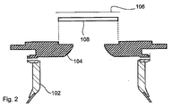
電子ビーム装置100は2個の部品、すなわち電子ビームを発生して成形する組立体103を収容し保護するチューブ体102と、窓箔106や、電子ビーム装置100の内部が真空圧になったときに窓箔106が押し潰されてしまうのを防止する箔支持プレート108などの電子ビームの出口部分に関する構成要素を担持するフランジ104とを含んで構成されている。さらに、電子ビーム装置の作動時には、箔は過度の熱作用を受ける。そのために、箔支持プレート108は使用時に、箔106に発生した熱を装置の箔から伝導により逃がすという重要な目的も果たすのである。箔の温度をほどほどに維持することで、箔106の十分に長い寿命を達成することができる。
The
製造において、銅製の支持プレート108はフランジ104に接着されるのであり、この段階ではフランジ104はチューブ体102から分離されている。フランジ104は一般にステンレス鋼で作られる。その後、窓箔106が箔支持プレート108の全周沿いに伸長する線に沿って支持プレート108に対して接着され(図示していないが、図3の接着線210と同様位置にて接着が行われる)、また、余った窓箔106は切除される。その後、例えば伝熱に関する特性を改善するために、箔106に被覆を施すことができる。フランジ104はその後チューブ体102に取付けられて密封ハウジングが形成される。
In manufacturing, the
本発明の発明者は、電子ビーム装置が例えば酸素を含む雰囲気の中で使用される場合には、このような従来のやり方は適切でないことを発見した。このような環境の下では、加速された電子は、強い侵食性物質であるオゾンを発生させることになる。オゾンは銅製の支持材を腐食し、このことはハウジングの密封状態および電子ビーム装置の機能を危うくする。さらに加えて、食品パッケージを製造するパッケージ機械では、パッケージの製造開始前の機械部品の殺菌に過酸化水素がしばしば使用されている。従って、銅製の支持材は十分に過酸化水素に触れることになる。過酸化水素は銅製の支持材に対する強い腐食性物質でもあるのだ。 The inventor of the present invention has found that such a conventional approach is not appropriate when the electron beam device is used, for example, in an atmosphere containing oxygen. Under such circumstances, the accelerated electrons generate ozone, which is a strong erodible substance. Ozone corrodes the copper support, which compromises the sealing of the housing and the function of the electron beam device. In addition, in packaging machines that produce food packages, hydrogen peroxide is often used to sterilize machine parts prior to the start of package production. Therefore, the copper support material is sufficiently exposed to hydrogen peroxide. Hydrogen peroxide is also a strong corrosive substance for copper supports.
最も影響を受けやすい箇所は、箔106との接着線における銅製部分である。ここでは、たった数十分の一ミリメートルほどの接着線の下側に腐食が生じるだけで上述した悪い結果をもたらすのである。
The most susceptible location is the copper portion of the bond line with the
本発明は、電子ビーム発生装置の電子出口窓の組立て方法を提供することによってこの問題の解決を図ることを目的とするものであり、この組立て方法とは、電子ビーム発生装置のハウジングに箔支持プレートを配置する段階と、窓箔を少なくとも1本の連続した接着線に沿って箔支持プレートに接着する段階と、少なくとも1本の接着線より半径方向外方へ伸長する前記窓箔のスカート部分を少なくとも1本の連続した取付け線に沿ってハウジングに取付ける段階とを含んで成る。 An object of the present invention is to solve this problem by providing a method for assembling an electron exit window of an electron beam generator, which is a method of supporting a foil on a housing of an electron beam generator. Placing the plate; adhering the window foil to the foil support plate along at least one continuous bond line; and a skirt portion of the window foil extending radially outward from the at least one bond line Attaching to the housing along at least one continuous attachment line.
本発明の方法には幾つかの利点がある。1つはハウジングに対する箔の取付けが密封状態を形成することであり、このことが銅製の支持プレートを、腐食や密封性崩壊をもたらす腐食性物質の影響から保護することになる。 The method of the present invention has several advantages. One is that the attachment of the foil to the housing creates a hermetic seal, which protects the copper support plate from the effects of corrosive materials that cause corrosion and hermetic collapse.
好ましい実施例は、従属請求項に記載されている。 Preferred embodiments are described in the dependent claims.
本発明はまた、電子ビーム発生装置の電子出口窓組立体をも含む。この電子出口窓組立体は箔支持プレートおよび窓箔を含んで構成される。前記箔支持プレートは電子ビーム発生装置のハウジングに取付けられており、前記窓箔は少なくとも1本の連続した接着線に沿って箔支持プレートに接着され、前記窓箔の少なくとも1本の接着線よりも半径方向外方へ伸長するスカート部分は少なくとも1本の連続した取付け線に沿ってハウジングに取付けられる。 The present invention also includes an electron exit window assembly for an electron beam generator. The electron exit window assembly includes a foil support plate and a window foil. The foil support plate is attached to the housing of the electron beam generator, and the window foil is bonded to the foil support plate along at least one continuous bond line, and from the at least one bond line of the window foil A radially outwardly extending skirt portion is attached to the housing along at least one continuous attachment line.
好ましい実施例は、従属請求項に記載されている。 Preferred embodiments are described in the dependent claims.
本発明の現在の好ましい実施例を、以下に添付図面を参照して非常に詳細に説明する。 The presently preferred embodiments of the invention are described in greater detail below with reference to the accompanying drawings.
図1および図2については既に記載した。図3は図2に類似するが分解されてはいない本発明の第1の実施例の横断面図である。図2および図3が類似しているのは、本発明を容易に理解できるようにするために意図したからである。しかしながら、この類似性が本発明の発明性を貶めると解釈するべきではない。何故なら、これには目に留まる以上に重要な内容があるからである。 1 and 2 have already been described. FIG. 3 is a cross-sectional view of a first embodiment of the present invention similar to FIG. 2 but not exploded. 2 and 3 are similar because they are intended to facilitate understanding of the present invention. However, this similarity should not be construed as giving up the inventiveness of the present invention. This is because there is more important content than this.
銅製の箔支持プレート208はフランジ204に接着される。可能な1つの接着技術はろう付けである。これとは別の段階において、チタンで作られた窓箔206が箔支持プレート208に接着される。可能な接着技術は、例えばレーザー溶接、電子ビーム溶接、ろう付け、超音波溶接、拡散接合および膠接着である。この接着は、銅製支持プレート208の周囲の接着線210に沿って行われる。この例示実施例での接着技術は、拡散接合である。接着線210は、電子ビーム装置の内部に真空圧を維持できるように、連続とされる。この「連続」の言葉は、接着線が無端すなわち閉結されていると定義するために使用される。さらに、接着線210は支持プレート208の周囲に沿って伸長するものと定義するべきである。接着線210は、フレーム支持プレート208の全周から距離を隔てた位置を伸長している。さらに、少なくとも1本の接着線210が形成される。従って、2本や3本の接着線を形成することができる。例えば、内側接着線および外側接着線を形成することができ、また、それらの2本の接着線を例えば互いに同心的に形成することができる。
A copper
フランジ204、銅製の支持プレート208および箔206は窓の副組立体を形成する。箔206はその後任意であるが被覆を施すことができ、また、被覆工程においては窓の副組立体だけを処理する必要がある。被覆工程の後、フランジ204がチューブ体202に接着される。可能な1つの接着技術は、例えばプラズマ溶接である。
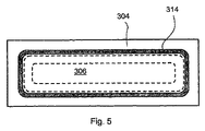
接着線210の半径方向外方に余った箔部分を切除する代わりに、円周方向のスカート部分212が取付けられないままに残される。このスカート部分212の自由端はその後フランジ204に形成されている膠214の塗付された溝216の中に位置される。膠はガスおよび水分のシール材として機能し、従って接着線210の周りの影響を受け易い部分の有害な腐食を防止する。膠は高温耐性膠であることが好ましい。溝216は連続していて、スカート部分212のための連続した取付け線を形成する。さらに、溝216はフランジ204に形成されている穴形状の全周から距離を隔てた位置に位置決めされる。この穴形状の上から支持プレート208が取付けられ、また、この穴形状を通して電子が通過するように構成される。
Instead of cutting off the excess foil portion radially outward of the
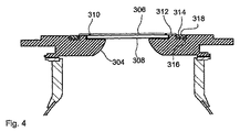
第2の実施例が図4に示されている。第1の実施例と同様なやり方で支持プレート308はフランジ304に取付けられ、箔306は接着線310に沿って支持プレート308に取付けられる。相違点は、溝316がスカート部分312の頂面の上からフレーム318を受入れることができるほど十分に大きく形成されていることである。前記フレーム318はフランジ304に対してスカート部分312を容易に拘束することができる。膠314はフレーム318を溝316に取付けるために使用されている。フレーム318は連続体であることが好ましい。
A second embodiment is shown in FIG.
図3および図4から、組み立て後に箔支持プレート208,308の一部分たりとも外部雰囲気、すなわち電子ビーム装置を取り囲む大気に対して露出されないこと、および、このことによって銅製の箔支持プレート208,308の腐食が防止されることを見て取ることができる。
3 and 4, it can be seen that after assembly, a portion of the
本発明は現在の好ましい実施例に関して記載されてきたが、特許請求の範囲の欄に記載した本発明の目的および範囲から逸脱することなくさまざまな改良や変更を行えることを理解するべきである。 Although the present invention has been described with reference to the presently preferred embodiment, it is to be understood that various modifications and changes can be made without departing from the object and scope of the invention as set forth in the appended claims.
接着線よりも半径方向外方へ伸長するスカート部分は、溝を形成することなくハウジングに直接に取付けることができる。同様に、スカート部分を拘束するために使用できるフレームは、ハウジングに直接に取付けることができる。 The skirt portion extending radially outward from the bond line can be attached directly to the housing without forming a groove. Similarly, a frame that can be used to constrain the skirt portion can be attached directly to the housing.
Claims (13)
電子ビーム発生装置のハウジングに箔支持プレート(208;308)を配置する段階と、
窓箔(206;306)を少なくとも1本の連続した接着線(210;310)に沿って箔支持プレート(208;308)に接着する段階と、
箔支持プレート(208;308)の一部分たりとも外部の大気に露出させないように、前記少なくとも1本の接着線(210;310)より半径方向外方へ伸長する前記窓箔のスカート部分(212;312)を少なくとも1本の連続した取付け線に沿ってハウジングに取付ける段階とを含んで成る電子出口窓の組立て方法。 A method of assembling an electron exit window of an electron beam generator,
Placing a foil support plate (208; 308) in the housing of the electron beam generator;
Adhering the window foil (206; 306) to the foil support plate (208; 308) along at least one continuous bond line (210; 310);
The window foil skirt portion (212; extending radially outward from the at least one bond line (210; 310) so that a portion of the foil support plate (208; 308) is not exposed to the outside atmosphere. Mounting 312) to the housing along at least one continuous mounting line.
前記箔支持プレート(208;308)が電子ビーム発生装置のハウジングに取付けられ、
前記窓箔(206;306)が少なくとも1本の連続した取付け線(210;310)に沿って箔支持プレート(208;308)に接着され、
箔支持プレート(208;308)の一部分たりとも外部の大気に露出させないように、前記少なくとも1本の連続した取付け線(210;310)よりも半径方向外方へ伸長する前記窓箔(206;306)のスカート部分(212;312)が少なくとも1本の連続した取付け線に沿ってハウジングに取付けられる電子出口窓組立体。 An electron exit window assembly of an electron beam generator comprising a foil support plate (208; 308) and a window foil (206; 306), comprising:
The foil support plate (208; 308) is attached to the housing of the electron beam generator;
The window foil (206; 306) is adhered to the foil support plate (208; 308) along at least one continuous attachment line (210; 310);
The window foil (206;) extending radially outward from the at least one continuous attachment line (210; 310) so that a portion of the foil support plate (208; 308) is not exposed to the outside atmosphere. 306) an electronic exit window assembly in which the skirt portion (212; 312) of the 306) is attached to the housing along at least one continuous attachment line.
Applications Claiming Priority (5)
| Application Number | Priority Date | Filing Date | Title |
|---|---|---|---|
| SE0900316A SE534156C2 (en) | 2009-03-11 | 2009-03-11 | Method for mounting a window for outgoing electrons and a window unit for outgoing electrons |
| SE0900316-1 | 2009-03-11 | ||
| US16013109P | 2009-03-13 | 2009-03-13 | |
| US61/160,131 | 2009-03-13 | ||
| PCT/SE2010/000018 WO2010104439A1 (en) | 2009-03-11 | 2010-01-27 | Method for assembling an electron exit window and an electron exit window assembly |
Publications (2)
| Publication Number | Publication Date |
|---|---|
| JP2012520457A true JP2012520457A (en) | 2012-09-06 |
| JP2012520457A5 JP2012520457A5 (en) | 2012-11-22 |
Family
ID=42728554
Family Applications (1)
| Application Number | Title | Priority Date | Filing Date |
|---|---|---|---|
| JP2011553981A Pending JP2012520457A (en) | 2009-03-11 | 2010-01-27 | Method for assembling electronic exit window and electronic exit window assembly |
Country Status (6)
| Country | Link |
|---|---|
| US (1) | US9183963B2 (en) |
| EP (1) | EP2406808B1 (en) |
| JP (1) | JP2012520457A (en) |
| CN (1) | CN102341885B (en) |
| SE (1) | SE534156C2 (en) |
| WO (1) | WO2010104439A1 (en) |
Families Citing this family (7)
| Publication number | Priority date | Publication date | Assignee | Title |
|---|---|---|---|---|
| SE533567C2 (en) | 2009-03-11 | 2010-10-26 | Tetra Laval Holdings & Finance | Method of mounting a window for outgoing electrons and a window unit for outgoing electrons |
| WO2013004566A2 (en) * | 2011-07-04 | 2013-01-10 | Tetra Laval Holdings & Finance S.A. | An electron beam device, a getter sheet and a method of manufacturing an electron beam device provided with said getter sheet |
| US9078747B2 (en) | 2011-12-21 | 2015-07-14 | Edwards Lifesciences Corporation | Anchoring device for replacing or repairing a heart valve |
| CN102881545B (en) * | 2012-09-18 | 2016-01-20 | 中国科学院上海应用物理研究所 | The method of electron ray source generation device and generation low dose rate electron ray |
| CN103077762B (en) * | 2012-12-19 | 2016-09-28 | 中国科学院上海应用物理研究所 | Electron ray source generation device and the method producing low dose rate electron ray |
| RU2648241C2 (en) * | 2016-09-01 | 2018-03-23 | Акционерное Общество "Нииэфа Им. Д.В. Ефремова" | Wide-aperture accelerator with planar electron-optical system |
| JP7162598B2 (en) * | 2017-01-26 | 2022-10-28 | カナディアン ライト ソース インコ. | Electron beam exit window in isotope production |
Citations (2)
| Publication number | Priority date | Publication date | Assignee | Title |
|---|---|---|---|---|
| JP2001305281A (en) * | 2000-04-25 | 2001-10-31 | Mitsubishi Electric Corp | Radiation source containment device |
| JP2007240454A (en) * | 2006-03-10 | 2007-09-20 | Hamamatsu Photonics Kk | Electron beam generator |
Family Cites Families (7)
| Publication number | Priority date | Publication date | Assignee | Title |
|---|---|---|---|---|
| DE4219562C1 (en) * | 1992-06-15 | 1993-07-15 | Fraunhofer-Gesellschaft Zur Foerderung Der Angewandten Forschung Ev, 8000 Muenchen, De | |
| US5391958A (en) * | 1993-04-12 | 1995-02-21 | Charged Injection Corporation | Electron beam window devices and methods of making same |
| US5621270A (en) * | 1995-03-22 | 1997-04-15 | Litton Systems, Inc. | Electron window for toxic remediation device with a support grid having diverging angle holes |
| US5962995A (en) | 1997-01-02 | 1999-10-05 | Applied Advanced Technologies, Inc. | Electron beam accelerator |
| ATE433193T1 (en) * | 2003-10-07 | 2009-06-15 | Koninkl Philips Electronics Nv | METHOD FOR PRODUCING A WINDOW THAT IS TRANSPARENT FOR ELECTRONS OF AN ELECTRON BEAM, IN PARTICULAR AN X-RAY SOURCE |
| JP2005156285A (en) * | 2003-11-25 | 2005-06-16 | Nhv Corporation | Electron beam irradiation equipment |
| KR100577473B1 (en) * | 2004-03-09 | 2006-05-10 | 한국원자력연구소 | A Large-Area Shower Electron Beam Irradiator with Field Emitters As an Electron Source |
-
2009
- 2009-03-11 SE SE0900316A patent/SE534156C2/en unknown
-
2010
- 2010-01-27 JP JP2011553981A patent/JP2012520457A/en active Pending
- 2010-01-27 US US13/255,297 patent/US9183963B2/en active Active
- 2010-01-27 WO PCT/SE2010/000018 patent/WO2010104439A1/en active Application Filing
- 2010-01-27 CN CN201080010766.8A patent/CN102341885B/en active Active
- 2010-01-27 EP EP10751075.2A patent/EP2406808B1/en active Active
Patent Citations (2)
| Publication number | Priority date | Publication date | Assignee | Title |
|---|---|---|---|---|
| JP2001305281A (en) * | 2000-04-25 | 2001-10-31 | Mitsubishi Electric Corp | Radiation source containment device |
| JP2007240454A (en) * | 2006-03-10 | 2007-09-20 | Hamamatsu Photonics Kk | Electron beam generator |
Also Published As
| Publication number | Publication date |
|---|---|
| SE534156C2 (en) | 2011-05-17 |
| CN102341885A (en) | 2012-02-01 |
| CN102341885B (en) | 2016-06-08 |
| US9183963B2 (en) | 2015-11-10 |
| EP2406808A1 (en) | 2012-01-18 |
| WO2010104439A1 (en) | 2010-09-16 |
| EP2406808B1 (en) | 2014-05-21 |
| EP2406808A4 (en) | 2013-06-26 |
| SE0900316A1 (en) | 2010-09-12 |
| US20120087842A1 (en) | 2012-04-12 |
Similar Documents
| Publication | Publication Date | Title |
|---|---|---|
| JP2012520457A (en) | Method for assembling electronic exit window and electronic exit window assembly | |
| JP5650672B2 (en) | Method for assembling electronic exit window and electronic exit window assembly | |
| JP4969851B2 (en) | X-ray tube | |
| JP6387364B2 (en) | Electron exit window foil, electron beam generator, method for providing electron exit window foil, and method for providing high performance electron beam device | |
| US8110974B2 (en) | Electron beam generating apparatus | |
| JP2001155855A (en) | Organic el element sealing method | |
| EP2881969B1 (en) | X-ray tube and method of manufacturing the same | |
| JP2005091107A (en) | Vacuum closed vessel and method for manufacturing it | |
| JP2012520457A5 (en) | ||
| JP3931888B2 (en) | Manufacturing method of vacuum package | |
| KR20210014737A (en) | Apparatus and method for thermal insulation of high temperature pressure sensors | |
| JP2006333971A (en) | Method of manufacturing vacuum structure and the vacuum structure | |
| JP2004146599A (en) | Package element | |
| JP2006049353A (en) | Manufacturing method of package | |
| JP2006333970A (en) | Method of manufacturing vacuum structure and the vacuum structure |
Legal Events
| Date | Code | Title | Description |
|---|---|---|---|
| A521 | Request for written amendment filed |
Free format text: JAPANESE INTERMEDIATE CODE: A523 Effective date: 20121003 |
|
| A621 | Written request for application examination |
Free format text: JAPANESE INTERMEDIATE CODE: A621 Effective date: 20121003 |
|
| A977 | Report on retrieval |
Free format text: JAPANESE INTERMEDIATE CODE: A971007 Effective date: 20131224 |
|
| A131 | Notification of reasons for refusal |
Free format text: JAPANESE INTERMEDIATE CODE: A131 Effective date: 20140110 |
|
| A521 | Request for written amendment filed |
Free format text: JAPANESE INTERMEDIATE CODE: A523 Effective date: 20140410 |
|
| A02 | Decision of refusal |
Free format text: JAPANESE INTERMEDIATE CODE: A02 Effective date: 20140729 |