JP2012519357A - Battery electrode and manufacturing method thereof - Google Patents
Battery electrode and manufacturing method thereof Download PDFInfo
- Publication number
- JP2012519357A JP2012519357A JP2011552016A JP2011552016A JP2012519357A JP 2012519357 A JP2012519357 A JP 2012519357A JP 2011552016 A JP2011552016 A JP 2011552016A JP 2011552016 A JP2011552016 A JP 2011552016A JP 2012519357 A JP2012519357 A JP 2012519357A
- Authority
- JP
- Japan
- Prior art keywords
- paste
- textile
- battery electrode
- grid
- battery
- Prior art date
- Legal status (The legal status is an assumption and is not a legal conclusion. Google has not performed a legal analysis and makes no representation as to the accuracy of the status listed.)
- Pending
Links
Images


Classifications
-
- H—ELECTRICITY
- H01—ELECTRIC ELEMENTS
- H01M—PROCESSES OR MEANS, e.g. BATTERIES, FOR THE DIRECT CONVERSION OF CHEMICAL ENERGY INTO ELECTRICAL ENERGY
- H01M4/00—Electrodes
- H01M4/02—Electrodes composed of, or comprising, active material
- H01M4/64—Carriers or collectors
- H01M4/70—Carriers or collectors characterised by shape or form
- H01M4/72—Grids
- H01M4/74—Meshes or woven material; Expanded metal
-
- H—ELECTRICITY
- H01—ELECTRIC ELEMENTS
- H01M—PROCESSES OR MEANS, e.g. BATTERIES, FOR THE DIRECT CONVERSION OF CHEMICAL ENERGY INTO ELECTRICAL ENERGY
- H01M10/00—Secondary cells; Manufacture thereof
- H01M10/06—Lead-acid accumulators
-
- H—ELECTRICITY
- H01—ELECTRIC ELEMENTS
- H01M—PROCESSES OR MEANS, e.g. BATTERIES, FOR THE DIRECT CONVERSION OF CHEMICAL ENERGY INTO ELECTRICAL ENERGY
- H01M4/00—Electrodes
- H01M4/02—Electrodes composed of, or comprising, active material
- H01M4/14—Electrodes for lead-acid accumulators
- H01M4/16—Processes of manufacture
- H01M4/20—Processes of manufacture of pasted electrodes
-
- H—ELECTRICITY
- H01—ELECTRIC ELEMENTS
- H01M—PROCESSES OR MEANS, e.g. BATTERIES, FOR THE DIRECT CONVERSION OF CHEMICAL ENERGY INTO ELECTRICAL ENERGY
- H01M4/00—Electrodes
- H01M4/02—Electrodes composed of, or comprising, active material
- H01M4/62—Selection of inactive substances as ingredients for active masses, e.g. binders, fillers
-
- H—ELECTRICITY
- H01—ELECTRIC ELEMENTS
- H01M—PROCESSES OR MEANS, e.g. BATTERIES, FOR THE DIRECT CONVERSION OF CHEMICAL ENERGY INTO ELECTRICAL ENERGY
- H01M4/00—Electrodes
- H01M4/02—Electrodes composed of, or comprising, active material
- H01M4/64—Carriers or collectors
- H01M4/70—Carriers or collectors characterised by shape or form
- H01M4/72—Grids
-
- H—ELECTRICITY
- H01—ELECTRIC ELEMENTS
- H01M—PROCESSES OR MEANS, e.g. BATTERIES, FOR THE DIRECT CONVERSION OF CHEMICAL ENERGY INTO ELECTRICAL ENERGY
- H01M2220/00—Batteries for particular applications
- H01M2220/20—Batteries in motive systems, e.g. vehicle, ship, plane
-
- H—ELECTRICITY
- H01—ELECTRIC ELEMENTS
- H01M—PROCESSES OR MEANS, e.g. BATTERIES, FOR THE DIRECT CONVERSION OF CHEMICAL ENERGY INTO ELECTRICAL ENERGY
- H01M4/00—Electrodes
- H01M4/02—Electrodes composed of, or comprising, active material
-
- Y—GENERAL TAGGING OF NEW TECHNOLOGICAL DEVELOPMENTS; GENERAL TAGGING OF CROSS-SECTIONAL TECHNOLOGIES SPANNING OVER SEVERAL SECTIONS OF THE IPC; TECHNICAL SUBJECTS COVERED BY FORMER USPC CROSS-REFERENCE ART COLLECTIONS [XRACs] AND DIGESTS
- Y02—TECHNOLOGIES OR APPLICATIONS FOR MITIGATION OR ADAPTATION AGAINST CLIMATE CHANGE
- Y02E—REDUCTION OF GREENHOUSE GAS [GHG] EMISSIONS, RELATED TO ENERGY GENERATION, TRANSMISSION OR DISTRIBUTION
- Y02E60/00—Enabling technologies; Technologies with a potential or indirect contribution to GHG emissions mitigation
- Y02E60/10—Energy storage using batteries
-
- Y—GENERAL TAGGING OF NEW TECHNOLOGICAL DEVELOPMENTS; GENERAL TAGGING OF CROSS-SECTIONAL TECHNOLOGIES SPANNING OVER SEVERAL SECTIONS OF THE IPC; TECHNICAL SUBJECTS COVERED BY FORMER USPC CROSS-REFERENCE ART COLLECTIONS [XRACs] AND DIGESTS
- Y10—TECHNICAL SUBJECTS COVERED BY FORMER USPC
- Y10T—TECHNICAL SUBJECTS COVERED BY FORMER US CLASSIFICATION
- Y10T29/00—Metal working
- Y10T29/10—Battery-grid making
-
- Y—GENERAL TAGGING OF NEW TECHNOLOGICAL DEVELOPMENTS; GENERAL TAGGING OF CROSS-SECTIONAL TECHNOLOGIES SPANNING OVER SEVERAL SECTIONS OF THE IPC; TECHNICAL SUBJECTS COVERED BY FORMER USPC CROSS-REFERENCE ART COLLECTIONS [XRACs] AND DIGESTS
- Y10—TECHNICAL SUBJECTS COVERED BY FORMER USPC
- Y10T—TECHNICAL SUBJECTS COVERED BY FORMER US CLASSIFICATION
- Y10T29/00—Metal working
- Y10T29/49—Method of mechanical manufacture
- Y10T29/49002—Electrical device making
- Y10T29/49108—Electric battery cell making
- Y10T29/49112—Electric battery cell making including laminating of indefinite length material
-
- Y—GENERAL TAGGING OF NEW TECHNOLOGICAL DEVELOPMENTS; GENERAL TAGGING OF CROSS-SECTIONAL TECHNOLOGIES SPANNING OVER SEVERAL SECTIONS OF THE IPC; TECHNICAL SUBJECTS COVERED BY FORMER USPC CROSS-REFERENCE ART COLLECTIONS [XRACs] AND DIGESTS
- Y10—TECHNICAL SUBJECTS COVERED BY FORMER USPC
- Y10T—TECHNICAL SUBJECTS COVERED BY FORMER US CLASSIFICATION
- Y10T29/00—Metal working
- Y10T29/49—Method of mechanical manufacture
- Y10T29/49002—Electrical device making
- Y10T29/49108—Electric battery cell making
- Y10T29/49115—Electric battery cell making including coating or impregnating
Abstract
ペースト用テキスタイル、繊維、すなわちスクリムを有する電池電極が、電極グリッド(例えば、打抜グリッドまたはエキスパンドメタルグリッド)を電池電極で被覆し、結合された不織繊維網で形成されたペースト用テキスタイルで覆われて作製される。この網は、平均長さが20μmより大きい1つまたは複数の繊維から形成される。様々な実施形態において、網は1つまたは複数の紡いだ連続繊維から形成される。電池電極は連続プロセスで作製され、1枚のシートに複数のグリッドが形成され、それに電極用活物質が被覆され、次にスクリムで覆われた後に裁断されて個別の電極となる。 A textile electrode for paste, a battery, i.e. a battery electrode with a scrim, covers the electrode grid (e.g. stamped grid or expanded metal grid) with the battery electrode and is covered with a paste textile formed by a bonded nonwoven fiber network. It is made. The mesh is formed from one or more fibers having an average length of greater than 20 μm. In various embodiments, the mesh is formed from one or more spun continuous fibers. The battery electrode is produced by a continuous process, a plurality of grids are formed on one sheet, coated with an electrode active material, then covered with a scrim, and then cut into individual electrodes.
Description
本出願は、2009年2月26日に出願された米国仮特許出願第61/155,763号の優先権を主張するものであり、その開示全体が参照により本明細書中に取り込まれる。 This application claims priority from US Provisional Patent Application No. 61 / 155,763, filed Feb. 26, 2009, the entire disclosure of which is incorporated herein by reference.
本発明は、電池(例えば、車両の始動、点灯、および点火用の電池、船舶用電池、商業用電池、産業用電池、ハイブリッド電気車両やマイクロハイブリッド車両で使用するための電池などの鉛蓄電池)の分野に関する。本発明は特に、ペースト用テキスタイルすなわちスクリムを含む電極または極板、または、別の形で、その上にペースト用テキスタイルすなわちスクリムを備える電極または極板に関する。 The present invention relates to batteries (for example, batteries for starting, lighting and igniting vehicles, marine batteries, commercial batteries, industrial batteries, lead-acid batteries such as batteries for use in hybrid electric vehicles and micro hybrid vehicles). Related to the field. In particular, the present invention relates to an electrode or electrode plate comprising a paste textile or scrim or, alternatively, an electrode or electrode plate comprising a paste textile or scrim thereon.
活物質がグリッドと電極または極板から剥離するのを防ぎ、および/または電池用の電極または極板の製造時に活物質を容易に扱えるようにするために、グリッド基板上に活物質を堆積した後にその支持体としてペースト用材料またはペースト紙を供給することは知られている。また、ポリエステル、ポリプロピレンやビスコースレーヨンでできたペースト用材料を紙の代わりに活物質中に埋め込んで、剥離や取り扱い上の問題を防止ないしは低減することも知られている。そのようなペースト紙や繊維では実現できない、ある種の利点(および/または特徴の組合わせ)がある。 In order to prevent the active material from peeling from the grid and the electrode or electrode plate and / or to make it easier to handle the active material when manufacturing the electrode or electrode plate for the battery, the active material was deposited on the grid substrate. It is known to later supply paste material or paste paper as its support. It is also known to prevent or reduce peeling and handling problems by embedding a paste material made of polyester, polypropylene or viscose rayon in an active material instead of paper. There are certain advantages (and / or combinations of features) that cannot be realized with such paste papers and fibers.
基本的利点およびその他の利点の概略 Overview of basic and other benefits
本発明で開示するような電池、電極、および/またはペースト用テキスタイルすなわちスクリム等は、以下に述べる利点またはそれ以外の利点の任意の1つまたは複数を備えることが望ましい。
1.従来のペースト用材料よりも酸の輸送特性が改良されたペースト用テキスタイル
2.従来のペースト用材料よりも電極の活物質への接着性が勝れたペースト用テキスタイル
3.従来のペースト用材料よりも強化された毛管作用を可能とするペースト用テキスタイル
4.従来のペースト用材料よりも優れた極板の強度および/または完全性(integrity)を提供するペースト用テキスタイル
5.導電率と静電容量を向上させた電極
6.正極、負極の高速連続製造時に利用できるペースト用テキスタイル
7.従来のペースト用材料に比べて、フラッシュ乾燥および/またはオーブン乾燥の温度が低くてよい(200〜400°F)材料特性を持つペースト用テキスタイル
8.より高速の極板製造ラインで利用でき、生産ラインの中断と故障を低減するペースト用テキスタイル
9.極板の硬化と乾燥プロセスを短縮し、および/または硬化時間を短縮できる材料特性を有するペースト用テキスタイル
10.従来のペースト用材料に比べて酸化反応を強化するペースト用テキスタイル
11.活物質の保持性を増し、活物質の脱落を制限することにより、サイクル性能を改良したペースト用テキスタイル
12.サイクル用途において特定のガラスマットセパレータをなくせる、ペースト用テキスタイル
13.電極と電池の鉛の低減(例えば、薄いグリッドの使用により)を可能とするペースト用テキスタイル
14.より高いリザーブキャパシティ(“RC”)を実現する電極
15.より高いサイクル数または20時間率容量(C20容量)を実現する電極
16.ストップ/スタートやマイクロハイブリッド用途を含む種々の用途において、酸の層状化(ストラティフィケーション)を緩和するペースト用テキスタイル
17.電池の使用寿命を延ばすペースト用テキスタイル
18.空気中を浮遊する鉛粒子とそれ以外の露出鉛の生成を低減し、および/または鉛の空気中放出と、従来のペースト紙で多く見られた潜在的な火災リスク(例えばバグハウス火災)を低下させることにより、製造プロセスを改良するペースト用テキスタイル
19.電池電極における生成効率と活物質変換を向上させるペースト用テキスタイル
20.電池のスクラップを低減し(例えば、従来型のペースト用材料の使用に起因するキャストオンストラップ溶接干渉でスクラップ化する必要のある電池の数を減少させることにより)、および/またはスクラップの回収率を向上させる、ペースト用テキスタイル
21.上記の1つまたは複数の利点に繋がり、従来の電池製造システムおよびプロセスに接続して使用可能な、従来型ペースト用材料の置き替えまたは代替
22.従来型のペースト紙とガラスマットセパレータの両方の代わりとなるペースト用テキスタイル
23.リザーブキャパシティを改善するペースト用テキスタイル
24.材料コスト、処理速度、清浄度に関連する製造コストを低減するペースト用テキスタイル
25.スタッカのダウンタイムとメンテナンス遅延を低減した製造を可能とするペースト用テキスタイル
26.従来の鉛蓄電池が達成しうる水準よりも高いサイクル仕様の用途への鉛蓄電池の使用を可能とするペースト用テキスタイル
The batteries, electrodes, and / or paste textiles or scrims as disclosed in the present invention desirably include any one or more of the advantages described below or other advantages.
1. 1. Paste textiles with improved acid transport properties over
一つの例示的実施形態は、グリッドと、グリッド上に与えられた活物質と、活物質上または活物質中に与えられたペースト用テキスタイルと、を備える電池電極に関し、ここで、ペースト用テキスタイルは、平均長さが20μmよりも大きい1つまたは複数の繊維を含んだ繊維網を含み、繊維は、一本当り約2デニールより大きい。 One exemplary embodiment relates to a battery electrode comprising a grid, an active material provided on the grid, and a paste textile provided on or in the active material, where the paste textile is A fiber network comprising one or more fibers having an average length greater than 20 μm, wherein the fibers are greater than about 2 denier per strand.
別の例示的実施形態は、長さと幅のあるグリッドと、グリッド上に与えられた活物質と、活物質上または活物質中に与えられたペースト用テキスタイルと、を備える電池電極に関し、ここで、ペースト用テキスタイルは、グリッドの長さと幅の合計の約半分の平均長さを有する1つまたは複数の繊維を含む繊維網を含む。 Another exemplary embodiment relates to a battery electrode comprising a length and width grid, an active material provided on the grid, and a paste textile provided on or in the active material, wherein The paste textile includes a fiber network that includes one or more fibers having an average length of about half the sum of the grid length and width.
別の例示的実施形態は、周縁を有するグリッドと、グリッド上に与えられた活物質と、活物質上または活物質中に与えられたペースト用テキスタイルと、を備える電池電極に関し、ここで、ペースト用テキスタイルは、第1の端と第2の端を有する1つまたは複数の繊維を含んだ繊維網を含み、各繊維の第1の端は、グリッドの周縁付近に実質的に位置する。 Another exemplary embodiment relates to a battery electrode comprising a grid having a perimeter, an active material provided on the grid, and a textile for paste provided on or in the active material, wherein the paste The textile for use includes a fiber network comprising one or more fibers having a first end and a second end, the first end of each fiber being substantially located near the periphery of the grid.
別の例示的実施形態は、電池電極の製造方法に関し、この方法は、鉛のシートを準備し、鉛シートを打ち抜いて1つまたは複数のグリッドを形成し、1つまたは複数のグリッドに活物質を付与し、紡いだ連続繊維でペースト用テキスタイルを形成し、1つまたは複数のグリッドのシート表面上にペースト用テキスタイルを付与し、その上に活物質とペースト用テキスタイルを備えた1つまたは複数のグリッドのシートを切断する、ことを含む。 Another exemplary embodiment relates to a method of manufacturing a battery electrode, the method comprising preparing a sheet of lead, stamping the lead sheet to form one or more grids, and active material in the one or more grids One or more comprising a continuous textile spun to form a textile for paste, a textile for pasting on the sheet surface of one or more grids, and having an active material and a textile for pasting thereon Cutting the grid sheet.
本発明によるシステムおよび方法の種々の実施形態におけるこれらおよびその他の特徴と利点は、本発明による種々の装置、構造、および/または方法の、さまざまな例示的実施形態の以下の詳細な記述において説明され、またはそれから明らかとなる。 These and other features and advantages of various embodiments of the systems and methods according to the present invention are described in the following detailed description of various exemplary embodiments of various devices, structures, and / or methods according to the present invention. Or will become clear from it.
本発明によるシステムおよび方法のさまざまな例示的実施形態が、以下の図面を参照して詳細に記述される。 Various exemplary embodiments of systems and methods according to this invention are described in detail with reference to the following drawings.
図面は必ずしも寸法通りとなっていないことを理解されたい。場合によっては、本発明を理解するのに不必要な、または他の詳細の読み取りを難しくする細部は省略した。本発明はここに図示した特定の実施形態に必ずしも限定されるものではないことは勿論であることを理解されたい。 It should be understood that the drawings are not necessarily drawn to scale. In some cases, details that are not necessary to understand the present invention or that make other details difficult to read have been omitted. It should be understood that the invention is not necessarily limited to the specific embodiments illustrated herein.
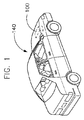
図1には、一つの例示的実施形態による電池100を含む車両140が示されている。車両140は自動車として示されているが、さまざまな他の実施形態によれば、車両には、特にオートバイ、バス、RV車、ボートなどを含む多岐にわたる車両が含まれてもよい。一実施形態によれば、車両140は移動目的に内燃エンジン(図示せず)を利用する。
FIG. 1 illustrates a
図1の電池100は、車両140および/または様々な車両システムの始動や運転に必要な動力の少なくとも一部を提供するように構成されている(例えば、始動(starting)、照明(lighting)、点火(ignition)システム(“SLI”)など)。さらに、様々な例示的実施形態によれば電池100は車両を含まない種々の用途に利用することが可能であり、それらのすべての用途は本発明の範囲内であることが意図されていることを理解されたい。
The
図1に示す電池100は、任意の種類の二次電池(例えば、充電可能な電池)を含んでよい。一つの例示的実施形態によれば、電池100は鉛蓄電池を含む。鉛蓄電池の様々な実施形態は、密封型(例えばメンテナンスフリー型)か非密封型(例えば液式型)かのいずれかである。
The
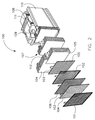
一つの例示的実施形態による電池100が図2に示されている。様々な実施形態において、電池100は電解液を含む容器すなわち筐体110の分離された隔室に備えられたセル要素を幾つか含んでいる。この図は自動車への用途に関するものであり、12〜16枚の極板104、105のグループがそれぞれのスタック107を構成し、そのスタック6つが標準的な自動車用12V電池を形成している。この明細書を読めば、個別の極板104、105の寸法と数と、特定のスタック107における極板104、105の寸法と数と、電池100を構成するスタック107の数とは、所望の最終利用目的によって大きく変化することが、当業者には明らかであろう。
A
様々な実施形態において、電池の筐体110は箱状の基体すなわち容器を含み、かつ少なくとも部分的にはモールド成形可能な樹脂でできている。複数のスタック107、つまり極板のブロックが、鉛蓄電池の容量に応じて直列に接続され、通常は硫酸水溶液である電解液と共に、電池の容器つまり筐体110の中に収納される。
In various embodiments, the
様々な実施形態において、電池100は前壁、側壁、後壁、底壁を有する隔室を備えている。様々な実施形態において、側壁と側壁の間に5つのセルパーティションすなわち仕切りが設けられて、6つの隔室が形成されており、これが通常の12Vの自動車用電池である。他の実施形態では、パーティションと隔室の数が変わって、異なる電圧の電池を形成する。様々な実施形態において、各隔室内には極板のブロックつまりスタック107があり、極板のブロックつまりスタック107には、それぞれが少なくとも1つの耳(lug)103を有する1つまたは複数の正極板104と負極板105と、各正極板104と負極板105の間に配置されて設けられたセパレータ106がある。様々な例示的実施形態において、正極板104と負極板105には、耳103が取り付けられたグリッド101と102が含まれていて、そこにはそれぞれ正極用または負極用の活物質すなわちペーストが被覆されている。
In various embodiments, the
筐体110にはカバー111が備えられ、様々な実施形態では、カバー111に、電解液をセルに追加し供用できるようするための端子ブッシュと注入チューブとが含まれる。注入チューブから電解液が漏れ出るような望ましくない状況を防止し、かつ電気化学反応において生成されるガスを排出するために、電池には1つまたは複数の注入口キャップおよび/またはベントキャップアセンブリも含まれていてもよい。
The
少なくとも1つの正極端子108と負極端子109が電池の上部または前部付近にある。これらの端子108、109は一般的に、電池のデザインに依存して電池筐体110のカバー111、および/または前面から突き出た部分を含んでいる。様々な実施形態において、端子108、109は、酸の漏洩を防ぐための端子シールアセンブリ(図示せず)を通して延びている。当分野で周知の上部、側部、またはコーナ部への構成を含め、様々な端子構成が可能であることは理解されるであろう。
At least one
図2には通常のキャストオンストラップ112も示されており、これは極板セットのそれぞれの耳部を電気的に接続するのに十分な長さを有する長方形の細長い本体部と、丸い先端を持ち上方向に延伸する部材とを含んでいる。図2には、負極端子に接続されるキャストオンストラップ接合用の耳部も示されている。図2に示すように、様々な実施形態に従って、キャストオンストラップは、端部隔室においてそれぞれの耳部と接続する本体部と、カバーの上に突き出る一体形成された端子とを含んでいる。
Also shown in FIG. 2 is a typical cast-on
各セル要素すなわちチャプタは、少なくとも1つの正極板104と、少なくとも1つの負極板105と、各正極板104と負極板105との間に位置するセパレータ106とを含む。セパレータ106は極板間に設けられ、短絡や、電池100内での反応中に望ましくない電流が生成されることを防止する。
Each cell element or chapter includes at least one
正極板104と負極板105は、その製造方法により種々のタイプに分類することができる。一例として、ペースト型電極を図3〜5に示す。様々な実施形態において、ペースト型電極は、グリッド基板と、その基板上に付与される電気化学的な活物質すなわち“ペースト”116とを含む。グリッドは、基板の機械的強度を増すために僅かにカルシウムを含む軟性合金でできていてもよい。
The
図3〜5を参照すると、正極板104と負極板105はそれぞれ、電気化学的活物質116を支持する鉛および/または鉛合金のグリッド113および/または115を含む。グリッド113および/または115は、電流の担い手である、正または負の活物質すなわちペースト116の間の電気的接触を提供する。グリッド113および/または115はまた、電池極板104および/または105の製造時に、堆積またはその他の方法で付与される電気化学的活物質116(例えばペースト)を支持するための基板としての役目もする。
Referring to FIGS. 3-5, the
詳細を以下で述べるように、鉛蓄電池のグリッド作製の周知の技術としては、(1)ブックモールド方式重力鋳造などのバッチ工程と、(2)ストリップエクスパンション、ストリップスタンピング、連続鋳造、連続鋳造後の圧延などの連続工程、とがある。これらの工程で製造されるグリッドは、それぞれの工程に固有な特徴的な性質を持ち、鉛蓄電池における挙動が異なる傾向がある。これは、特にペースト処理工程に関して言える。グリッドとしては、従来または最近の任意のグリッド製造工程により製造されたものを利用できることは理解されるであろう。そして本発明はここに開示したグリッドの設計に限定されるものではない。 As will be described in detail below, the well-known techniques for producing lead-acid battery grids include (1) batch processes such as book mold gravity casting, and (2) strip expansion, strip stamping, continuous casting, and continuous casting. There are continuous processes such as rolling. Grids manufactured by these processes have characteristic properties unique to each process, and tend to behave differently in lead-acid batteries. This is especially true for the paste processing step. It will be appreciated that the grid can be made by any conventional or recent grid manufacturing process. The present invention is not limited to the grid design disclosed herein.
様々な実施形態において、少なくともグリッドのうち、あるものは打抜グリッド113である。図3は活物質つまりペースト116を備えた打抜グリッド113(例えば正極板用のグリッド)の一つの例示的実施形態である。図4は図3の打抜グリッドであり、活物質を取り除いた状態を示している。様々な実施形態において、打抜グリッド113は、上枠要素、第1の側枠要素、第2の側枠要素、および底枠要素を含む枠を備えている。さまざまな実施形態において、打抜グリッド113は、電流を発生させる活物質つまりペースト116を保持する空間領域を画定するグリッドワイヤ114を含んでいる。様々な実施形態において、集電用の耳103が上枠要素と一体になっている。図3〜4では耳103は上枠要素の中心から外れているように描かれているが、そのかわりに耳103が中心にあってもよいし、または、第1の側枠要素または第2の側枠要素のいずれかの近くにあってもよい。上枠要素は、少なくとも耳の直下部分が拡大された導電部分を持っていて、耳へ向かう電流を最適化するようになっていてもよい。
In various embodiments, at least some of the grids are punched
底枠要素には1つまたは複数の下に延びる脚(図示せず)が形成されていて、打抜グリッドのその他の部分を電池容器の底から離すようになっていてもよい。様々な実施形態において、グリッドワイヤ114のうち少なくともあるものは、底から上に向かう長さ方向に沿って断面積が増えるか傾斜のついた形状となっていて、底部から上部に向かって増加する生成電流が通りやすくなるようにワイヤ114の電流搬送容量が最適化されている。第1の側枠要素と第2の側枠要素との間のワイヤ114の幅と間隔は、打抜グリッド113の幅方向にわたって実質的に電位が等しい点が存在するように前もって決められる。電気化学的ペーストを支え、および/またはペーストのペレットが形成されるようにするために、さまざまな実施形態においては打抜グリッド113に、上枠要素および/または底枠要素と平行で等間隔に離れた水平方向のワイヤも含まれている。ただし、図3〜4に示すように、水平ワイヤのうち少なくともあるものは上枠要素および/または底枠要素に対して等間隔でも平行でもないかもしれない。
The bottom frame element may be formed with one or more underlying legs (not shown) so that other portions of the stamped grid are separated from the bottom of the battery container. In various embodiments, at least some of the
色々な種類の打抜グリッドの形状が用いられる。例えば、米国特許第5,582,936号、第5,989,749号、第6,203,948号、第6,274,274号、第6,921,611号、第6,953,641号、および米国特許出願第10/996,168号、第11/086,525号、第10/819,489号、第60/904,404号を参照されたい。これらはすべて参照によりその全体がここに組み込まれるものとする。無限の数のグリッド設計が利用可能であり、従って、以下の説明は本発明を、説明のために示した図3〜5のグリッド設計に限定することを意図するものではないことは理解されたい。 Various types of punching grid shapes are used. For example, U.S. Pat. Nos. 5,582,936, 5,989,749, 6,203,948, 6,274,274, 6,921,611, 6,953,641 And U.S. Patent Application Nos. 10 / 996,168, 11 / 086,525, 10 / 819,489, 60 / 904,404. All of which are hereby incorporated by reference in their entirety. It should be understood that an unlimited number of grid designs are available and, therefore, the following description is not intended to limit the invention to the grid designs of FIGS. 3-5 shown for illustrative purposes. .
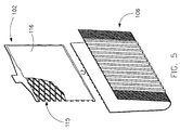
エキスパンドメタルグリッド115(例えば負極板用のグリッド)の一つの例示的実施形態を図5に示す。様々な実施形態において、エキスパンドメタルグリッドは、当業界において周知のように、1つのパターン(例えば図5に示すようなダイアモンドパターンなど)をしていて、底枠要素と、耳と一体の上枠要素とを有している。 One exemplary embodiment of an expanded metal grid 115 (eg, a grid for a negative electrode plate) is shown in FIG. In various embodiments, the expanded metal grid is in a pattern (eg, a diamond pattern as shown in FIG. 5), as is well known in the art, and the bottom frame element and the top frame integral with the ear. And have elements.
図3〜5を参照すると、グリッドワイヤの断面はグリッドの製造プロセスにより変わり得る。しかし、電池ペーストの接着性を改善するために、様々な実施形態においてグリッドワイヤが機械的に整形または再仕上げされることがある。好適なペースト接着特性が与えられる形状でありさえすれば、いかなる数のグリッドワイヤ形状が使用されてもよいことは理解されるであろう。例えば、ワイヤの断面は、略楕円形、略長方形、略ダイアモンド形、略菱形、略六角形、および/または略八角形を含む任意の断面形状であってよい。電池グリッドにおいて、各グリッドワイヤ部分が異なる断面構成となっていてもよいし、あるいは各グリッドワイヤ部分が同一ないしは類似の断面構成となっていてもよい。ただし、各グリッドワイヤ部分が同一の断面形状となっていることが好ましい。必要に応じて、グリッドは、垂直ワイヤ要素のみ、または水平ワイヤ要素のみ、または垂直と水平の両方のワイヤ要素を変形されることもある。 3-5, the cross section of the grid wire may vary depending on the grid manufacturing process. However, to improve the adhesion of the battery paste, the grid wires may be mechanically shaped or refinished in various embodiments. It will be appreciated that any number of grid wire shapes may be used, as long as the shape provides suitable paste adhesion characteristics. For example, the cross-section of the wire may be any cross-sectional shape including substantially elliptical, substantially rectangular, substantially diamond-shaped, substantially diamond-shaped, substantially hexagonal, and / or substantially octagonal. In the battery grid, each grid wire portion may have a different cross-sectional configuration, or each grid wire portion may have the same or similar cross-sectional configuration. However, it is preferable that each grid wire part has the same cross-sectional shape. If desired, the grid may be deformed with only vertical wire elements, only horizontal wire elements, or both vertical and horizontal wire elements.
活物質すなわちペースト116は、一般的に鉛ベースの材料(例えば、電池の充電/放電の異なる段階において、一酸化鉛PbO、二酸化鉛PbO2、鉛Pb、硫酸鉛PbSO4など)であり、それが貼り付け、堆積、またはそれ以外の方法でグリッド上に付与される。ペーストの組成は、当技術分野で周知のように、必要とする電力、コスト、電池の使用環境などにより決定される。様々な実施形態において、鉛蓄電池の活物質116は、鉛酸化物と硫酸と水を混合して準備される。鉛酸化物は硫酸と反応して、1、3、および/または4塩基性の鉛硫化物を形成する。繊維やエキスパンダ等の、乾式添加物が活物質に添加されてもよい。例えば様々な実施形態において、微粉化されたカーボン(例えば油煙やカーボンブラック)、バリウム硫化物、および種々のリグニン等のエキスパンダが活物質中に含まれてもよい。様々な実施形態において、その混合物を乾燥した後に水を再添加して所望の粘稠度のペーストを形成する。
The active material or
正極グリッド上に与えられた活物質(例えば、二酸化鉛[PbO2])は、通常微粒子状になっており、従って、電解液が、正極板上の二酸化鉛微粒子を通って拡散、浸透することができる。負極板の活物質である、スポンジ状の鉛は通常多孔質で反応性が高く、従って電解液は、負極板上のスポンジ鉛を通って拡散、浸透することができる。 The active material (for example, lead dioxide [PbO 2 ]) applied on the positive grid is usually in the form of fine particles, and therefore, the electrolyte diffuses and permeates through the lead dioxide fine particles on the positive electrode plate. Can do. Sponge-like lead, which is the active material of the negative electrode plate, is usually porous and highly reactive, so that the electrolyte can diffuse and permeate through the sponge lead on the negative electrode plate.
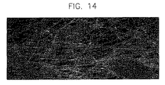
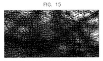
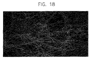
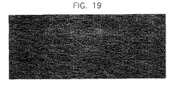
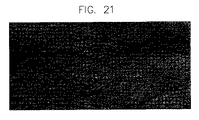
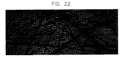
次に図6を参照すると、これはグリッド101と活物質116とペースト用テキスタイル、繊維、すなわちスクリム120とを含む電池極板すなわち電極の切欠き図であるが、様々な実施形態においては、ペースト用テキスタイル、繊維、すなわちスクリム120は、グリッド101上に付与された活物質116の表面の内部または上部に設けることができる。様々な実施形態によるペースト用テキスタイルすなわちスクリム120が、拡大されて図7〜22に示されている。様々な実施形態において、ペースト用テキスタイルすなわちスクリム120は、接着された、不織布網を含んでもよい。より具体的には、ペースト用テキスタイルすなわちスクリム120は、繊維が点結合された、不織布網を含んでもよい。点結合は、ペースト用スクリム材料の活物質への接着性を改善する効果がある。ただし、ペースト用テキスタイルが不織布である必要はなく、織物、ゆるい織物、編み物などであってもよいことは理解されたい。また、ペースト用テキスタイルは接着されなくてもよい。様々な実施形態において、ペースト用テキスタイルすなわちスクリム120は、湿式の漉き処理を利用して製造される。
Reference is now made to FIG. 6, which is a cutaway view of a battery plate or electrode that includes a
様々な実施形態において、ペースト用テキスタイルすなわちスクリム120は、厚さが0.06mm〜5mm、好ましくは0.06mm〜0.5mm、もっと好ましくは0.06mm〜0.25mmである。しかしながら、当業者であれば理解されるように、ペースト用テキスタイルの厚さは、意図する用途と、コールドクランキングアンペア、サイクリングすなわち20時間率容量、またはリザーブキャパシティ等の、電池の所望の性質とに部分的に依存する。
In various embodiments, the paste textile or
様々な実施形態において、ペースト用テキスタイルすなわちスクリム120は、従来のペースト紙の代わりに使用されてもよい。別の実施形態において、ペースト用テキスタイル(例えば不織布材料すなわちスクリム)が従来のペースト紙に積層、またはそれ以外の方法で付与されて、そのようなペースト紙を利用する電極、またはそのようなペースト紙を利用する電極を用いた電池の、特性および性質を改良する。前述したものよりもさらに薄いペースト用テキスタイルすなわちスクリムが、ペースト紙に積層、結合、またはそれ以外の方法で付与されて利用されてもよいことも理解されるであろう。
In various embodiments, the paste textile or
様々な実施形態において、ペースト用テキスタイルは従来のペースト紙または材料と共に、またはそれに加えて使用されてもよい。例えば、様々な実施形態において、ペースト用テキスタイルすなわちスクリムは、正極のみに関して従来のペースト用材料の代わりに利用されてもよい。他の様々な実施形態において、ペースト用テキスタイルすなわちスクリムは、負極のみに関して従来のペースト紙の代わりに利用されてもよい。ペースト用テキスタイルすなわちスクリムが1つの種類の電極(例えば正極または負極)だけに関して従来のペースト紙の代わりに用いられ、そして、従来のペースト紙または材料が、もう一方の種類の電極に関して用いられる場合は、ペースト用テキスタイルすなわちスクリム120と従来のペースト紙または材料との視覚的な違いが、製造時に正極と負極との区別を容易にし、電極の混同と不注意による誤認識(例えば、負極を正極とする、またその逆の取り違え)を減らすことができる。
In various embodiments, the paste textile may be used with or in addition to conventional paste paper or materials. For example, in various embodiments, paste textiles or scrims may be utilized in place of conventional paste materials for positive electrodes only. In various other embodiments, a paste textile or scrim may be utilized in place of conventional paste paper for the negative electrode only. If the paste textile or scrim is used in place of a conventional paste paper for only one type of electrode (eg positive or negative electrode) and the conventional paste paper or material is used for the other type of electrode The visual difference between the paste textile or
複数の種類の電極(例えば、正極と負極)に関して、ペースト用テキスタイルすなわちスクリムを従来のペースト紙の代わりに用いる様々な実施形態において、1つの電極(例えば正極)に関して用いられるペースト用テキスタイルがもう一方の種類の電極((例えば負極)に用いられるペースト用テキスタイルとは(例えば異なる着色または彩色により)視覚的に異なっていてもよく、正極と負極との識別を容易にし、それによりそれらの電極の混同や不注意による誤認識を減少させることが可能である。 In various embodiments where paste textiles or scrims are used in place of conventional paste paper for multiple types of electrodes (eg, positive and negative electrodes), the other is the paste textile used for one electrode (eg, positive electrode). May be visually different (for example by different coloring or coloring) from the paste textile used for this type of electrode (eg negative electrode), thereby facilitating the discrimination between the positive electrode and the negative electrode It is possible to reduce misrecognition due to confusion and carelessness.
様々な実施形態において、ペースト用テキスタイルすなわちスクリム120は、約0.15〜約2.0オンス/平方ヤード(約4.25〜56.7g/m2)の重量範囲すなわち密度範囲を有する。ここで厚さの場合と同様に、ペースト用テキスタイルの好適な重量すなわち密度範囲は、意図する適用方法と、コールドクランキングアンペア、サイクリングすなわち20時間率容量、またはリザーブキャパシティ等の所望の性能特性とに部分的に依存する。様々な実施形態において、重量範囲または密度の選択は、ペースト用テキスタイルと、本来のままの活物質との間の結合の性質も変化させる可能性もある。様々な実施形態において、重量または密度範囲は、従来の製造工程と、電極を従来の電池製造の工程、システムおよび装置を利用して容易かつ経済的に製造しなければならないという制約とに依存する。
In various embodiments, the paste textile or
様々な実施形態において、ペースト用テキスタイル120は主として繊維またはマイクロファイバで構成される。様々な実施形態において、繊維またはマイクロファイバは、ポリエステル、ポリプロピレン、ビスコースレーヨン、ポリアミド(例えばナイロン)等の、1つまたは複数の熱可塑性樹脂から造られる。
In various embodiments, the
様々な実施形態において、ペースト用テキスタイル120は紡がれた連続繊維から造られる。紡がれた連続繊維を利用することで、酸の輸送と、ペースト用テキスタイル120の活物質116への接着が改良される。さらに、連続単繊維を使用することで、そのような繊維で形成されたペースト用テキスタイル120は、繊維が概して面内にある、つまりペースト用テキスタイルすなわちスクリム120の面と平行になるために、向上した機械的性質を示す。
In various embodiments, the
しかしながら、当業者であれば、ペースト用テキスタイルは、短繊維またはカット繊維を含む複数の繊維で作られ得ることが理解されるであろう。様々な実施形態において、短繊維またはカット繊維は長さが異なり、通常1.5mm〜15mmの範囲の長さを有する。しかしながら、繊維は任意の好適な長さであってもよいことは理解されたい。しかし、様々な実施形態において、短繊維またはカット繊維の平均長さは、20μmよりも大きい。 However, those skilled in the art will appreciate that the paste textile can be made of a plurality of fibers including short fibers or cut fibers. In various embodiments, the short or cut fibers are different in length and typically have a length in the range of 1.5 mm to 15 mm. However, it should be understood that the fibers may be of any suitable length. However, in various embodiments, the average length of short fibers or cut fibers is greater than 20 μm.
様々な実施形態において、繊維またはマイクロファイバは通常丸い断面形状をしている。様々な実施形態において、繊維の直径は10μm〜25μmである。様々な実施形態において、繊維は、一本当りのデニールが1〜10、好ましくは2〜4の範囲にある。様々な例示的実施形態において、繊維は、約2より大きく、10以下のデニールを有する。別の実施形態においては、繊維は、約2より大きく、4以下のデニールを有する。様々な実施形態において、繊維の表面はほぼ平滑であり、テキスチャはほとんどないか、全くない。他の様々な実施形態において、繊維は他の断面形状を有する。 In various embodiments, the fibers or microfibers typically have a round cross-sectional shape. In various embodiments, the fiber diameter is between 10 μm and 25 μm. In various embodiments, the fibers have a denier per fiber in the range of 1-10, preferably 2-4. In various exemplary embodiments, the fibers have a denier greater than about 2 and no greater than 10. In another embodiment, the fibers have a denier greater than about 2 and no greater than 4. In various embodiments, the surface of the fiber is substantially smooth and has little or no texture. In various other embodiments, the fibers have other cross-sectional shapes.
繊維はまた、混紡すなわち複数の成分を含んでもよい。例えば、繊維が種々の共重合体の混紡となっていてもよい。様々な実施形態において、繊維は2成分の芯鞘型繊維でできている。他の実施形態では、繊維はホモ重合体つまり単独重合体である。ある実施形態において、繊維またはマイクロファイバは、カーボンベースである(即ち、純カーボンであるかまたは、カーボンブラック、黒鉛、膨張黒鉛、ナノチューブ、ナノファイバ、アセチレンブラック、及びそれらの派生物を無制限に含む他のタイプのカーボンを含む)。繊維またはマイクロファイバは、純カーボンおよび/または他のタイプのカーボン、または、任意の割合の純カーボンおよび/または他のタイプのカーボン、でできていてもよい。 The fiber may also include a blend or multiple components. For example, the fiber may be a blend of various copolymers. In various embodiments, the fibers are made of bicomponent core-sheath fibers. In other embodiments, the fibers are homopolymers or homopolymers. In certain embodiments, the fibers or microfibers are carbon-based (ie, pure carbon or include unlimited carbon black, graphite, expanded graphite, nanotubes, nanofibers, acetylene black, and derivatives thereof. Including other types of carbon). The fibers or microfibers may be made of pure carbon and / or other types of carbon, or any proportion of pure carbon and / or other types of carbon.
様々な実施形態において、ペースト用テキスタイルすなわちスクリムは、化成時に活物質の変換を助ける、二酸化チタン(TiO2)、黒鉛、カーボンブラックなどを含む1つまたは複数の添加物と共に装着される。様々な実施形態において、ペースト用テキスタイル、材料、スクリム、および/または繊維は化学的に処理される。様々な実施形態において、ペースト用テキスタイルまたは繊維は、カーボン処理すなわち含浸されてもよい。様々な実施形態において、ペースト用テキスタイルまたは繊維は、二酸化チタン(TiO2)、シリカ、粘土、タルク、酸化物などのつや消し剤で処理されてもよい。つや消し剤で処理することにより、ペースト用テキスタイルまたは繊維には、表面粗さ、またはテキスチャが出てきて、活物質への付着が改善され、および/またはペースト用テキスタイルまたは繊維の濡れ性が改善される。さらに、ペースト用テキスタイルまたは繊維は、濡れ性を強化するために、水溶性シリコンなどの界面活性剤または湿潤剤を含んでもよい。 In various embodiments, the paste textile or scrim is mounted with one or more additives including titanium dioxide (TiO 2 ), graphite, carbon black, etc. that aid in the conversion of the active material during conversion. In various embodiments, paste textiles, materials, scrims, and / or fibers are chemically treated. In various embodiments, the paste textile or fiber may be carbon treated or impregnated. In various embodiments, the paste textile or fiber may be treated with a matting agent such as titanium dioxide (TiO 2 ), silica, clay, talc, oxide, and the like. By treating with a matting agent, the paste textile or fiber will have surface roughness, or texture, which improves adhesion to the active material and / or improves the wettability of the paste textile or fiber. The In addition, the paste textile or fiber may include a surfactant or wetting agent such as water soluble silicone to enhance wettability.
様々な実施形態において、ペースト用スクリムすなわちテキスタイルは、単一の連続繊維から網を生成し、それを所望の形と寸法に切断して形成される。そのような実施形態において、網から切断された後のペースト用テキスタイルの繊維の平均長さは、ペースト用テキスタイルの長さと幅の平均にほぼ等しい。様々な実施形態において、ペースト用スクリムすなわちテキスタイルは、電池電極上で1工程で化成されてもよいし、別工程で化成しておいてそれを次の工程で電極板状に被覆してもよい。ペースト用テキスタイルすなわちスクリムが電極板状で化成される実施形態においては、ペースト用テキスタイルすなわちスクリムは、ペーストの付与されたグリッドシートまたは、シートが個々のペースト付きグリッドすなわち極板に切断される前の極板に供給される。 In various embodiments, paste scrims or textiles are formed by creating a net from a single continuous fiber and cutting it into the desired shape and dimensions. In such embodiments, the average length of the paste textile fibers after being cut from the net is approximately equal to the average length and width of the paste textile. In various embodiments, the paste scrim or textile may be formed in one step on the battery electrode or formed in a separate step and coated in the next step into an electrode plate. . In embodiments where the paste textile or scrim is formed in the form of an electrode plate, the paste textile or scrim is applied to the grid sheet to which the paste is applied or before the sheet is cut into individual pasted grids or plates. Supplied to the electrode plate.
再び図5を参照すると、様々な実施形態において、1つまたは複数の電池セパレータ106が正極と負極との間の電導を遮断するために用いられる。セパレータ材料は一般的には微小孔性であり、正極および負極からイオンが貫通できる。自動車電池用のセパレータは一般的には連続体として形成されて巻き取られている。それを図5に示すように折曲げて、1つまたは複数の端部に沿って密封して袋状としてその中に電極(例えば図5に示すように負極板、または図2に示すように正極板)を入れる。
Referring again to FIG. 5, in various embodiments, one or
様々な実施形態において、セパレータ材料は通常、ほぼ均一な厚さと、ほぼ均一な微細孔分布を有する。微細孔が分布していることにより、運転時に全体として均一な電流密度が確保され、その結果電極の均一な充放電と電池効率の最大化の達成が支援される。セパレータ106は通常1つまたは複数のリブ(例えば図5に示されているような)を含み、セパレータの剛性を上げる役目を果たす。
In various embodiments, the separator material typically has a substantially uniform thickness and a substantially uniform micropore distribution. The distribution of the fine holes ensures a uniform current density as a whole during operation, and as a result, helps to achieve uniform charge / discharge of the electrode and maximization of battery efficiency.
様々な例示的実施形態において、繊維スクリム布は、従来のペースト紙とセパレータ(例えばガラスマットセパレータ)の両方を1枚のシート状物質で置き換える。一つの例示的実施形態に従って構成される電池は、従来の基本的電池(baseline batteries)に比べてリザーブキャパシティが顕著に改良される。電池の環境条件下で分解するペースト紙をなくすことで、材料コストが減少し、製造スピードが向上し、かつ製造工程の清浄度が向上する(例えばペースト紙からの塵がなくなる)。ガラスマットセパレータをなくすことで、製造装置のダウンタイムとメンテナンスによる遅延が減少する。 In various exemplary embodiments, the fiber scrim cloth replaces both conventional paste paper and a separator (eg, a glass mat separator) with a single sheet of material. A battery configured in accordance with one exemplary embodiment has a significant improvement in reserve capacity compared to conventional baseline batteries. By eliminating the paste paper that decomposes under the environmental conditions of the battery, the material cost is reduced, the manufacturing speed is improved, and the cleanliness of the manufacturing process is improved (for example, dust from the paste paper is eliminated). By eliminating the glass mat separator, production equipment downtime and maintenance delays are reduced.
従来の鉛蓄電池は、マイクロハイブリッド車のサイクル仕様に対応できない。しかし、本実施形態に従う、従来のペースト紙とセパレータを繊維スクリム布で置き換えた鉛蓄電池は、従来の鉛蓄電池では対応できないマイクロハイブリッド車用のスタートストップ用途などの高サイクル仕様下での運転が可能である。 Conventional lead-acid batteries cannot meet the cycle specifications of micro hybrid vehicles. However, according to this embodiment, the conventional lead-acid battery in which the paste paper and separator are replaced with a fiber scrim cloth can be operated under high-cycle specifications such as start / stop applications for micro hybrid vehicles that cannot be handled by conventional lead-acid batteries. It is.
セパレータ材料は種々の材料(例えば、ポリオレフィン、ゴム、フェノールーホルムアルデヒド レゾルシノール、ガラスマット、微小孔性PVC、および焼結PVC)で構成される。様々な実施形態において、セパレータ106は分子量の大きいポリオレフィンから成る微小孔性シートで構成される。使用されるポリオレフィンの例としては、ポリエチレン、ポリプロピレン、ポリブテン、エチレンープロピレン共重合体、エチレンーブテン共重合体、プロピレン−ブテン共重合体、およびエチレンープロピレン−ブテン共重合体、などがある。
The separator material is composed of various materials (eg, polyolefin, rubber, phenol-formaldehyde resorcinol, glass mat, microporous PVC, and sintered PVC). In various embodiments, the
様々な実施形態において、セパレータ106は少なくとも1つの可塑剤も含む。可塑剤は、水溶性であっても水に不溶であってもよい。使用される可塑剤の例としては、有機エステル、エポキシ化合物、リン酸塩エステル、炭化水素材料、および低分子量ポリマ、等がある。
In various embodiments, the
様々な実施形態において、セパレータ106は不活性充填剤材料も含有する。充填剤は、水溶性であっても水に不溶であってもよい。ただし、充填剤の第1の役割は、任意の可塑剤を吸収し、組成を保持して、可塑剤に溶融されないようにすることである。好適な充填剤は、微粉化された乾燥シリカである。ただし、その他の充填剤(例えば、カーボンブラック、炭塵、黒鉛、金属の酸化物と水酸化物、金属炭酸塩、ミネラル、ゼオライト、沈降金属ケイ酸塩、アルミナシリカゲル、木粉、木質繊維と樹皮製品、ガラス粒子、バリウム硫酸塩・無機塩・酢酸塩・硫酸塩・リン酸塩・硝酸塩・炭酸塩などの塩、および/またはこれらの組合わせなど)も利用できる。また、充填剤の濡れ性を向上させるために、既知または最新開発の湿潤剤(例えば、アルキルベンゼンスルホン酸ナトリウム、ラウリル硫酸ナトリウム、スルホコハク酸ジオクチルナトリウム、イソクチルフェニルポリエトキシエタノールなど)も利用可能であることを理解されたい。
In various embodiments, the
様々な実施形態において、セパレータ106は安定剤または酸化防止剤を含んでいる。様々な実施形態において、従来の安定剤または、4,4’−チオビス(6−tert−ブチル−m−クレゾール)(“Santonox”)や 2,6−ジ−tert−ブチル−4−メチルフェノール (“Ionol”) 等の酸化防止剤を用いてもよい。
In various embodiments, the
セパレータに1つまたは複数のリブが設けられている場合、リブは幾つかの既知または最新開発のポリマ組成(例えば、セパレータと同一組成、その他のポリオレフィン、塩化ポリビニル、および/またはそれらの充填組成、発泡組成など)でできていてもよい。リブは何通りもの方法で提供されてもよい。例えば、リブは押出(シートと一体で、または個別に)で形成されてもよい。リブはまた、溝切またはエンボス加工で形成されてもよい。リブが個別に成形される場合、加熱シールや接着剤による方法を含む、当技術分野において周知の任意の方法でシートまたはベース網に接着あるいはその他の結合が行なわれる。 If the separator is provided with one or more ribs, the ribs may have several known or newly developed polymer compositions (eg, the same composition as the separator, other polyolefins, polyvinyl chloride, and / or their filling composition, It may be made of a foamed composition or the like. Ribs may be provided in a number of ways. For example, the ribs may be formed by extrusion (integral with the sheet or separately). The ribs may also be formed by grooving or embossing. If the ribs are individually molded, they are bonded or otherwise bonded to the sheet or base network by any method known in the art, including heat sealing and adhesive methods.
図5には特定のリブ構成が示されているが、当業者であれば、グリッド設計、極板設計、および/または電池に少なくとも部分的に依存して、任意の種類のリブ形状を利用してもよいことがわかるであろう。 Although a particular rib configuration is shown in FIG. 5, those skilled in the art will utilize any type of rib shape, depending at least in part on the grid design, plate design, and / or battery. You will understand that
セパレータ106の厚さは、それが使われる電池100の種類によって変わってくる。一般的に、基体網の厚さは、1〜50ミリインチ(”ミル”)(約0.025mm〜約1.27mm)の範囲である。鉛蓄電池の場合、好適な厚さは一般的に10〜40ミル(約0.25mm〜約1.02mm)の範囲である。各リブの高さは、極板間隔の仕様により大きく変化する。通常、基体から5〜200ミル(約0.13mm〜約5.08mm)の高さとなっており、好適な範囲は10〜100ミル(約0.25mm〜約2.54mm)である。
The thickness of the
種々の材料間の電気化学ポテンシャルを利用して電気を発生させる様々な化学反応が研究され、商業的に実装されてきた。一般的に、Besenhard,J.O.編、「電池材料ハンドブック(Handbook of Battery Materials)」、Wiley−VCH Verlag GmbH、Weinheim、Germany、1999、およびLinden,D.編、「電池ハンドブック(Handbook of Batteries)」第2版、McGraw Hill Inc.、New York、N.Y.、199を参照されたい。両者の開示内容を本願に引用して援用する。 Various chemical reactions that generate electricity using the electrochemical potential between various materials have been studied and implemented commercially. See generally Besenhard, J. et al. O. Ed., “Handbook of Battery Materials”, Wiley-VCH Verlag GmbH, Weinheim, Germany, 1999, and Linden, D. et al. Ed., “Handbook of Batteries”, 2nd edition, McGraw Hill Inc. New York, N .; Y. 199. Both disclosures are incorporated herein by reference.
鉛蓄電池の極板は従来、鉛合金のグリッド材料などの導電性の支持体に活物質すなわちペーストを塗布して作製される。極板はその製造方法によって分類することができる。例えば、電池極板製造の一方法では、先ず炉中で鉛を溶融し、次にその溶融鉛合金をストリップ鋳造機に供給する。ストリップ展伸工程において、一般的には鋳造または鍛造された鉛のストリップが穿孔され、ストリップ面の上下に拡げられて、次に引き伸ばされてダイアモンド形状のグリッドが形成される。様々な実施形態において、巻き取り機にストリップが巻き取られて、鉛合金ストリップのコイルが保管されてその後の使用に備えられる。様々な実施形態において、ストリップは圧延されてもよい。電池のグリッド材料を形成するために、様々な実施形態において、ストリップがエキスパンダに供給されて、そこでコイルストリップを裁断、溝入れ、展伸を行なってグリッドが形成される。 An electrode plate of a lead storage battery is conventionally produced by applying an active material, that is, a paste to a conductive support such as a grid material of a lead alloy. The electrode plate can be classified according to its manufacturing method. For example, in one method of manufacturing a battery plate, lead is first melted in a furnace and then the molten lead alloy is fed to a strip casting machine. In the strip extension process, typically a strip of lead that has been cast or forged is perforated, expanded above and below the strip surface, and then stretched to form a diamond-shaped grid. In various embodiments, the strip is wound on a winder and a coil of lead alloy strip is stored for subsequent use. In various embodiments, the strip may be rolled. To form a battery grid material, in various embodiments, a strip is fed to an expander where the coil strip is cut, grooved, and stretched to form a grid.
グリッド材料は、他の既知または最新開発のプロセスを利用して製造されてもよい。例えば、上述したように、鋳造工程(例えば、溶融合金を鋳型に注入することによる)、打抜工程、または連続圧延によって形成されてもよい。グリッドまたは極板の製造時に、グリッドワイヤは(ペーストの接着を改善するために)再仕上げまたは再成形されてもよい。 The grid material may be manufactured using other known or latest developed processes. For example, as described above, it may be formed by a casting process (for example, by injecting a molten alloy into a mold), a punching process, or continuous rolling. During the manufacture of the grid or plate, the grid wire may be refinished or reshaped (to improve paste adhesion).
次に展伸されたストリップすなわちワイヤグリッド材料上に、活物質すなわちペーストが塗布されるか、別の方法(例えば、従来の糊付装置により貼り付ける方法)で付与される。様々な実施形態において、ペースト用テキスタイル、繊維すなわちスクリム、またはペースト紙などの1つまたは複数のペースト用材料が活物質の片面または両面に付与される。様々な実施形態において、ペースト用材料またはペースト紙が連続工程により提供されてもよい。 Next, an active material or paste is applied on the spread strip or wire grid material, or is applied by another method (for example, a method of applying by a conventional gluing device). In various embodiments, one or more pasting materials such as pasting textiles, fibers or scrims, or paste paper are applied to one or both sides of the active material. In various embodiments, the paste material or paste paper may be provided in a continuous process.
様々な実施形態において、グリッド材料と、活物質つまりペーストと、ペースト用材料(例えばペースト用テキスタイルすなわちスクリム)が、ストリップが極板に切断される分割機に供給される。ストリップを切断することにより、ペースト用テキスタイルすなわちスクリムを形成している連続繊維も複数の繊維に切断される。その平均長さは、ストリップから切断される極板面の長さと幅の和の約半分である。ストリップから切断された極板は、電池極板のペーストの平坦でない部分を平滑化するために平坦化されるか、別の方法で修正されてもよい。様々な実施形態において、極板は、フラッシュ乾燥のために(例えば、コンベヤに載って)炉を通り抜けた後に、使用するまで積み重ねられてもよい。従来、フラッシュ乾燥は開放式のガスフレームまたは炉を利用して行なわれ、極板は、例えば、約260℃(約500°F)の通常の送風乾燥炉で10〜15秒の乾燥が行なわれる。しかし様々な実施形態において、ペースト用テキスタイルすなわちスクリムを含む電極または極板は、それより低い温度で乾燥されてもよい(例えば、約93〜約205℃(約200〜約400°F)。乾燥後、電池極板は、当業者には周知の化学処理を受ける。ペーストが塗布された極板は、次に一般的に高温高湿下で長時間硬化させて、遊離した鉛の酸化を進め、それ以外に極板の結晶構造を調整する。 In various embodiments, the grid material, the active material or paste, and the paste material (eg, paste textile or scrim) are fed to a divider where the strip is cut into plates. By cutting the strip, the continuous fiber forming the paste textile or scrim is also cut into a plurality of fibers. The average length is about half of the sum of the length and width of the plate surface cut from the strip. The plate cut from the strip may be flattened or otherwise modified to smooth the uneven portions of the battery plate paste. In various embodiments, the plates may be stacked until they are used after passing through a furnace for flash drying (eg, on a conveyor). Conventionally, flash drying is performed using an open gas flame or a furnace, and the electrode plate is dried for 10 to 15 seconds in a normal blast drying furnace at about 260 ° C. (about 500 ° F.), for example. . However, in various embodiments, the electrode or plate including the paste textile or scrim may be dried at a lower temperature (eg, about 93 to about 205 ° C. (about 200 to about 400 ° F.). The battery plate is then subjected to chemical treatments well known to those skilled in the art, and the paste coated plate is then generally cured at high temperature and high humidity for a long time to promote oxidation of the free lead. In addition, the crystal structure of the electrode plate is adjusted.
従来のポリオレフィン製の電池セパレータは、一般的には、高分子量のポリオレフィンと不活性充填物質、および/または可塑剤の混合物を混練し、その混合物をシート状に成形し、その後不活性充填剤および/または可塑剤の一部を溶剤を使ってシートから抽出するという工程によって製造される。 Conventional polyolefin battery separators are generally kneaded with a mixture of a high molecular weight polyolefin and an inert filler, and / or a plasticizer, the mixture is formed into a sheet, and then the inert filler and It is manufactured by a process of extracting a part of the plasticizer from the sheet using a solvent.
硬化の後、極板は電池に組み立てられる。それぞれの電池極板がグループ分けされて集められ、セパレータ材料で包まれるか、差し込まれるか、他の方法で分離されるかして、全体で極板の組が出来上がる。例えば、普通の電池の設計では、電池の中の1枚置きの極板(例えば、それぞれの負極板)が袋状の電池セパレータの中に挿入される。袋は、電池セットの中で、袋の中の極板と隣接する極板とのセパレータとして作用する。極板の組は容器の中で組み立てられて、電池が構成される。 After curing, the electrode plate is assembled into a battery. Each battery electrode plate is grouped and collected and wrapped in separator material, plugged in, or otherwise separated to complete the electrode plate set as a whole. For example, in a normal battery design, every other electrode plate (eg, each negative electrode plate) in the battery is inserted into a bag-shaped battery separator. The bag acts as a separator between the electrode plate in the bag and the adjacent electrode plate in the battery set. A set of electrode plates is assembled in a container to form a battery.
組立時に、正電極の耳同士が一緒に結合され、また負電極の耳同士が一緒に結合される。これは、一般的に、組み立てられた電池の積層体を取り上げて、逆さにし、モールド中に準備された溶融鉛の中に耳を浸すことにより形成される、キャストオンストラップ法を用いて達成される。電流が電池全体を流れるようにするために、複数の積層体のキャストオンストラップが一緒に結合される。さらに、カバーまたはケースの外に延びる端子電極が設けられて、自動車の電気システム、あるいはこの電池の電力を使おうとする他のシステムとの電気接続が可能となる。 During assembly, the positive electrode ears are joined together and the negative electrode ears are joined together. This is generally achieved using a cast-on-strap method, which is formed by taking the assembled battery stack, turning it upside down and immersing the ears in the molten lead prepared in the mold. The A plurality of laminate cast-on straps are combined together to allow current to flow through the battery. In addition, terminal electrodes that extend outside the cover or case are provided to allow electrical connection to the vehicle's electrical system or other systems that want to use the power of this battery.
様々な実施形態において、カバーを含む電池の筐体が電池セルを包含するように設けられる。様々な実施形態において、電池カバーにある注液口を通して電池筐体を電解液で満たすために、電池の筐体は、酸性の電解液中に浸漬される。電池筐体に電解液を満たした後、電池は電解液から取出される。残留した電解液の被膜や、埃やその他の塵が洗浄除去されて、電池を出荷に備える。電池筐体の外表面を洗浄する前に、注液口は栓をされて、電池筐体内に洗浄液が入らないようにする。 In various embodiments, a battery housing including a cover is provided to contain the battery cells. In various embodiments, the battery housing is immersed in an acidic electrolyte to fill the battery housing with electrolyte through a liquid inlet in the battery cover. After filling the battery housing with the electrolyte, the battery is removed from the electrolyte. The remaining electrolyte coating, dust and other dust are washed away to prepare the battery for shipment. Before the outer surface of the battery casing is cleaned, the liquid inlet is plugged so that the cleaning liquid does not enter the battery casing.
最初の洗浄に続いて、電池に通電して電気化学的な処理が行なわれ、これは、硫酸鉛または塩基性の硫酸鉛を二酸化鉛(正極)または鉛(負極)に変換するためである。このプロセスを“化成”プロセスと呼ぶ。 Following the initial cleaning, the battery is energized and subjected to an electrochemical treatment, in order to convert lead sulfate or basic lead sulfate to lead dioxide (positive electrode) or lead (negative electrode). This process is called the “chemical conversion” process.
本発明を以下の実施例で更に説明する。この実施例は説明を目的とするものであり、制限するためのものではない。 The invention is further illustrated in the following examples. This example is for purposes of illustration and not for limitation.
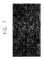
スタートストップ用の鉛蓄電池が、上記の方法で製造された電極を用いて組み立てられた。より具体的には、正極は、打抜グリッド(PowerFrame(登録商標)グリッド)と活物質と図7及び8に示すペースト用テキスタイルすなわちスクリムとを含んでいた。ペースト用テキスタイルは、円形断面でほぼ平滑なテキスチャを有する、PETの連続単独重合体で構成された。このペースト用テキスタイルは、繊度が0.5オンス/平方ヤード(約17.0g/m2)で厚さが4.3ミル(約0.11mm)の点結合タイプであった。マイクロファイバの直径は約12〜16μmであり、繊維のデニールは一本当り約2.2であった。 A start-stop lead-acid battery was assembled using the electrodes manufactured by the above method. More specifically, the positive electrode included a stamped grid (PowerFrame® grid), an active material, and a paste textile or scrim as shown in FIGS. The paste textile was composed of a continuous homopolymer of PET with a circular cross section and a nearly smooth texture. This paste textile was a point-bond type with a fineness of 0.5 ounces / square yard (about 17.0 g / m 2 ) and a thickness of 4.3 mils (about 0.11 mm). The microfiber diameter was about 12-16 μm and the fiber denier was about 2.2 per strand.
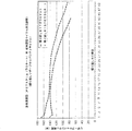
組み立てられた電池のストップ/スタートのサイクル特性を、同様な構成の負極とポリエチレンセパレータと、打抜グリッド(PowerFrame(登録商標)グリッド)と活物質とその上の従来型のペースト紙とを有する正極とを備える電池のストップ/スタートのサイクル特性に対比してテストした。2つの電池のストップ/スタートのサイクル容量を比較したグラフを図23に示す。 A positive / negative electrode, polyethylene separator, punched grid (PowerFrame® grid), active material, and conventional paste paper on top of the cycle characteristics of assembled battery stop / start The battery was tested against the stop / start cycle characteristics of the battery. A graph comparing the stop / start cycle capacities of the two batteries is shown in FIG.
上記の製法による電極を用いた、改良型の浸漬式鉛蓄電池を組み立てた。より具体的には、正極は、打抜グリッド(PowerFrame(登録商標)グリッド)と活物質と図7及び8に示すペースト用テキスタイルすなわちスクリムとを含んでいた。ペースト用テキスタイルは、円形断面でほぼ平滑なテキスチャを有する、PETの連続単独重合体で構成された。このペースト用テキスタイルは、繊度が0.5オンス/平方ヤード(約17.0g/m2)で厚さが4.3ミル(約0.11mm)の点結合タイプであった。マイクロファイバの直径は約12〜16μmであり、繊維のデニールは一本当り約2.2であった。 An improved immersion lead-acid battery using the electrode produced by the above-described manufacturing method was assembled. More specifically, the positive electrode included a stamped grid (PowerFrame® grid), an active material, and a paste textile or scrim as shown in FIGS. The paste textile was composed of a continuous homopolymer of PET with a circular cross section and a nearly smooth texture. This paste textile was a point-bond type with a fineness of 0.5 ounces / square yard (about 17.0 g / m 2 ) and a thickness of 4.3 mils (about 0.11 mm). The microfiber diameter was about 12-16 μm and the fiber denier was about 2.2 per strand.
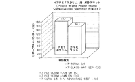
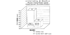
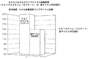
完成した鉛蓄電池の繰り返しリザーブキャパシティサイクル試験をして、グリッドと活物質は同じであるが正極はペースト用テキスタイルの代わりにペースト紙を用い、セパレータのガラスマットは高サイクル用途の一般的標準品を用いた電池の繰り返しリザーブキャパシティサイクルとの比較を行なった。2つの電池の繰り返しリザーブキャパシティサイクルを比較したグラフを図24に示す。さらに図25、26には、2つの電池のリザーブキャパシティ時間と、アンペア−時間単位で示したC20容量との棒グラフをそれぞれに示す。図27には、2つの電池のEN 50% DODライフサイクル試験を比較した棒グラフを示す。
Repeated reserve capacity cycle test of the finished lead acid battery, the grid and the active material are the same, but the positive electrode uses paste paper instead of the textile for paste, and the separator glass mat is a general standard for high cycle applications A comparison was made with the repetitive reserve capacity cycle of the battery using. A graph comparing the repeated reserve capacity cycles of the two batteries is shown in FIG. Further, FIGS. 25 and 26 respectively show bar graphs of the reserve capacity time of two batteries and the C20 capacity expressed in ampere-hour units. FIG. 27 shows a bar graph comparing the
本明細書において使用されている、“略”、“約”、“実質的に”、およびこれに類似の用語は、本開示の主題に関わる当業者による一般的かつ許容された用法に調和する、広範な意味を有することが意図される。本開示を精査する当業者であれば、これらの用語は、記述されかつ特許請求されるある特徴を、与えられた正確な数値の範囲に制限することなしに記述可能とすることが意図されていることを、理解できるであろう。従って、これらの用語は、記述されかつ特許請求される主題に関する、僅かな、あるいは重大でない修正または変更が、添付の特許請求の範囲に述べる本発明の範囲内であるとみなされることを指示するものと解釈されるべきである。 As used herein, the terms “substantially”, “about”, “substantially”, and similar terms accord with common and accepted usage by those of ordinary skill in the art for the subject matter of this disclosure. Are intended to have a broad meaning. Those skilled in the art reviewing this disclosure are intended to allow these terms to be described without limiting certain described and claimed features to the exact numerical ranges given. You will understand that. Accordingly, these terms indicate that minor or minor modifications or changes with respect to the subject matter described and claimed are considered to be within the scope of the invention as set forth in the appended claims. Should be interpreted.
本説明における相対位置に関する参照(例えば、“上”と“下”)は、種々の要素を図中における配置として識別するために用いられているに過ぎないことに留意されたい。特定の部品の方向は、それの実際の適用に大きく依存していることが認識されるべきである。 It should be noted that references to relative positions in this description (eg, “up” and “down”) are only used to identify various elements as arrangements in the figures. It should be appreciated that the orientation of a particular part is highly dependent on its actual application.
本開示において、”連結された”という用語は、2つの部材を直接的または間接的に互いに結合することを意味している。そのような結合は、本質的に静的であっても、本質的に動的であってもよい。そのような結合は、2つの部材または2つの部材と任意の追加的な中間部材が、相互に1つの結合体として形成されるか、または2つの部材または2つの部材と任意の追加的な中間部材が、相互に接続されることによって実現される。そのような結合は、本質的に永続性のものであってもよいし、本質的に取り外し可能または解放可能であってもよい。 In the present disclosure, the term “coupled” means that two members are directly or indirectly coupled to each other. Such binding may be static in nature or dynamic in nature. Such a connection may be formed by two members or two members and any additional intermediate members being formed as one combination with each other, or two members or two members and any additional intermediate This is realized by connecting the members to each other. Such a connection may be permanent in nature, or may be essentially removable or releasable.
本開示において、”電気的に結合された”という用語は、2つ以上の部材を、その部材間に電流が形成されるように直接的または間接的に互いに接続または結合していることを意味している。そのような電気的な結合は、本質的に静的であっても、本質的に動的であってもよい。そのような電気的な結合は、2つの部材または2つの部材と任意の追加的な中間部材が、相互に1つの結合体として形成されるか、または2つの部材または2つの部材と任意の追加的な中間部材が、相互に接続されることによって実現される。そのような電気的な結合は、本質的に永続性のものであってもよいし、本質的に取り外し可能または解放可能であってもよい。 In this disclosure, the term “electrically coupled” means that two or more members are connected or coupled to each other directly or indirectly such that an electric current is formed between the members. is doing. Such electrical coupling may be static in nature or dynamic in nature. Such an electrical coupling is such that two members or two members and any additional intermediate members are formed as one combination with each other, or two members or two members and any additional The intermediate members are realized by being connected to each other. Such electrical coupling may be permanent in nature, or may be essentially removable or releasable.
種々の例示的実施形態に示した電池および/または電池部品の構成および配置は、説明のためだけであることに留意することが重要である。本開示においては本発明の僅か数例の実施形態を詳細に記述したに過ぎないが、この開示を精査する当業者であれば、ここに開示した主題の新規性のある教示および利点から著しく乖離することなしに、多くの修正
(例えば、サイズ、寸法、構造、種々の要素の形状および割合、パラメータ値、取付方法、材料の使用方法、色、方向などの変更)が可能であることは容易に理解できるであろう。例えば、一体的に形成されているように示されている要素が複数の部品または要素で構成されてもよいし、複数の部品として示されている要素が一体的に形成されていてもよいし、インタフェースの操作が逆転もしくは違うものに変更されてもよいし、構造および/または部材の長さまたは幅、あるいはシステムのコネクタまたはその他の要素が変更されてもよいし、および/または要素間に与えられる調節位置の性質または数が(例えば、係合するスロットの数や係合するスロットの寸法や係合の種類などの変更により)変更されてもよい。任意の工程あるいは方法のステップの順序もしくは順番が、別の実施形態で変更あるいは再配列されてもよい。本発明の精神と範囲から外れることなしに、種々の例示的実施形態の設計、動作条件、および配置に関して、その他の代替、修正、変更、省略を行うことが可能である。
It is important to note that the configuration and arrangement of the batteries and / or battery components shown in the various exemplary embodiments is for illustration only. Although only a few embodiments of the present invention have been described in detail in this disclosure, those skilled in the art who have reviewed this disclosure will depart significantly from the novel teachings and advantages of the disclosed subject matter. It is easy to make many modifications (for example, changes in size, dimensions, structure, shapes and proportions of various elements, parameter values, mounting methods, material usage, colors, orientations, etc.) without having to Will understand. For example, an element shown as being integrally formed may be composed of a plurality of parts or elements, or an element shown as a plurality of parts may be integrally formed. The operation of the interface may be reversed or changed, or the length and width of the structure and / or members, or the connectors or other elements of the system may be changed and / or between elements The nature or number of adjustment positions provided may be changed (eg, by changing the number of engaging slots, the size of engaging slots, the type of engagement, etc.). The order or order of any process or method steps may be varied or rearranged in other embodiments. Other substitutions, modifications, changes and omissions may be made with respect to the design, operating conditions, and arrangement of the various exemplary embodiments without departing from the spirit and scope of the present invention.
Claims (23)
前記グリッド上に与えられた活物質と、
前記活物質上または活物質中に与えられたペースト用テキスタイルと、
を備え、
前記ペースト用テキスタイルは、平均長さが20μmよりも大きい1つまたは複数の繊維を含んだ繊維網を含み、
前記繊維は、一本当り約2デニールより大きいことを特徴とする、電池電極。 The grid,
An active material provided on the grid;
A textile for paste applied on or in the active material;
With
The paste textile comprises a fiber network comprising one or more fibers having an average length greater than 20 μm;
A battery electrode, wherein the fibers are greater than about 2 denier per strand.
前記グリッド上に与えられた活物質と、
前記活物質上または活物質中に与えられたペースト用テキスタイルと、
を備え、
前記ペースト用テキスタイルは、前記グリッドの長さと幅の合計の約半分の平均長さを有する1つまたは複数の繊維を含む繊維網を含むことを特徴とする、電池電極。 A grid having a length and a width;
An active material provided on the grid;
A textile for paste applied on or in the active material;
With
The battery electrode according to claim 1, wherein the paste textile includes a fiber network including one or more fibers having an average length of about half of the total length and width of the grid.
前記グリッド上に与えられた活物質と、
前記活物質上または活物質中に与えられたペースト用テキスタイルと、
を備え、
前記ペースト用テキスタイルは、第1の端と第2の端を有する1つまたは複数の繊維を含んだ繊維網を含み、
前記各繊維の第1の端は、前記グリッドの前記周縁付近に実質的に位置することを特徴とする、電池電極。 A grid having a periphery;
An active material provided on the grid;
A textile for paste applied on or in the active material;
With
The paste textile includes a fiber network including one or more fibers having a first end and a second end;
The battery electrode according to claim 1, wherein a first end of each fiber is substantially located near the periphery of the grid.
前記鉛シートを打ち抜いて1つまたは複数のグリッドを形成し、
前記1つまたは複数のグリッドに活物質を付与し、
紡いだ連続繊維でペースト用テキスタイルを形成し、
前記1つまたは複数のグリッドのシート表面上に前記ペースト用テキスタイルを付与し、
その上に活物質とペースト用テキスタイルを備えた前記1つまたは複数のグリッドのシートを切断する、
ことを含む、電池電極の製造方法。 Prepare lead sheet,
Punching out the lead sheet to form one or more grids;
Applying an active material to the one or more grids;
Forming textiles for paste with spun continuous fibers,
Applying the paste textile on the sheet surface of the one or more grids;
Cutting said one or more grid sheets with active material and paste textile thereon,
The manufacturing method of a battery electrode including this.
Applications Claiming Priority (3)
| Application Number | Priority Date | Filing Date | Title |
|---|---|---|---|
| US15576309P | 2009-02-26 | 2009-02-26 | |
| US61/155,763 | 2009-02-26 | ||
| PCT/US2009/065108 WO2010098796A1 (en) | 2009-02-26 | 2009-11-19 | Battery electrode and method for manufacturing same |
Related Child Applications (1)
| Application Number | Title | Priority Date | Filing Date |
|---|---|---|---|
| JP2015075665A Division JP2015122339A (en) | 2009-02-26 | 2015-04-02 | Battery electrode pair |
Publications (2)
| Publication Number | Publication Date |
|---|---|
| JP2012519357A true JP2012519357A (en) | 2012-08-23 |
| JP2012519357A5 JP2012519357A5 (en) | 2013-01-17 |
Family
ID=41479219
Family Applications (4)
| Application Number | Title | Priority Date | Filing Date |
|---|---|---|---|
| JP2011552016A Pending JP2012519357A (en) | 2009-02-26 | 2009-11-19 | Battery electrode and manufacturing method thereof |
| JP2015075665A Pending JP2015122339A (en) | 2009-02-26 | 2015-04-02 | Battery electrode pair |
| JP2017107379A Pending JP2017147242A (en) | 2009-02-26 | 2017-05-31 | Battery electrode pair |
| JP2020218676A Active JP7156589B2 (en) | 2009-02-26 | 2020-12-28 | battery electrode pair |
Family Applications After (3)
| Application Number | Title | Priority Date | Filing Date |
|---|---|---|---|
| JP2015075665A Pending JP2015122339A (en) | 2009-02-26 | 2015-04-02 | Battery electrode pair |
| JP2017107379A Pending JP2017147242A (en) | 2009-02-26 | 2017-05-31 | Battery electrode pair |
| JP2020218676A Active JP7156589B2 (en) | 2009-02-26 | 2020-12-28 | battery electrode pair |
Country Status (6)
| Country | Link |
|---|---|
| US (2) | US8846252B2 (en) |
| EP (1) | EP2401782B1 (en) |
| JP (4) | JP2012519357A (en) |
| KR (1) | KR101827528B1 (en) |
| CN (2) | CN102439763B (en) |
| WO (1) | WO2010098796A1 (en) |
Cited By (2)
| Publication number | Priority date | Publication date | Assignee | Title |
|---|---|---|---|---|
| JP2017526107A (en) * | 2014-06-17 | 2017-09-07 | オーシーヴィー インテレクチュアル キャピタル リミテッド ライアビリティ カンパニー | Anti-sulfation adhesive mat for lead-acid batteries |
| WO2020080423A1 (en) * | 2018-10-16 | 2020-04-23 | 株式会社Gsユアサ | Lead storage battery |
Families Citing this family (22)
| Publication number | Priority date | Publication date | Assignee | Title |
|---|---|---|---|---|
| KR101827528B1 (en) | 2009-02-26 | 2018-02-09 | 존슨 컨트롤스 테크놀러지 컴퍼니 | Battery electrode and method for manufacturing same |
| EP2427038A1 (en) * | 2010-09-01 | 2012-03-07 | LANXESS Deutschland GmbH | EMF-shielded plastic organo-sheet hybrid structural component |
| EP2538471A1 (en) * | 2011-06-20 | 2012-12-26 | Glatfelter Gernsbach GmbH & Co. KG | Multifunctional web for use in a lead-acid battery |
| US9368781B2 (en) * | 2011-06-27 | 2016-06-14 | Gs Yuasa International Ltd. | Terminal portion for storage batteries, plastic encapsulated terminal for storage batteries, method for producing the same, storage battery provided with terminal portion, and automobile equipped with storage battery |
| JP6125515B2 (en) * | 2011-09-12 | 2017-05-10 | エキサイド テクノロジーズ エス.エー.ユー.Exide Technologies S.A.U. | A flooded lead acid battery with an electrode having a pasting substrate |
| PL2768046T3 (en) * | 2011-10-11 | 2021-08-30 | Exide Technologies, S.L.U. | Flooded lead-acid battery with electrodes comprising a pasting substrate |
| RU2638532C2 (en) | 2012-03-08 | 2017-12-14 | Аркэктив Лимитед | Improved construction of lead-acid battery |
| DE102012102461B4 (en) * | 2012-03-22 | 2013-10-10 | Vb Autobatterie Gmbh & Co. Kgaa | Process for the production of electrodes for lead-acid batteries, electrode and lead-acid battery produced thereafter |
| KR101585839B1 (en) | 2012-07-24 | 2016-01-14 | 가부시끼가이샤 도시바 | Secondary battery |
| US10096819B2 (en) * | 2012-09-20 | 2018-10-09 | Arcactive Limited | Method for forming an electrical connection to a conductive fibre electrode and electrode so formed |
| US20140120339A1 (en) | 2012-10-31 | 2014-05-01 | Cabot Corporation | Porous carbon monoliths templated by pickering emulsions |
| KR102475499B1 (en) | 2014-06-17 | 2022-12-08 | 오웬스 코닝 인텔렉츄얼 캐피탈 엘엘씨 | Water loss reducing pasting mats for lead-acid batteries |
| EP3660961A1 (en) | 2014-12-11 | 2020-06-03 | Arcactive Limited | Method and machine for manufacturing a fibre elecrode |
| PL3086384T3 (en) * | 2015-04-23 | 2018-03-30 | Johns Manville Europe Gmbh | Tubular bags of the cartridge belt type for lead-acid batteries made from a textile sheet fabric |
| CN104779402B (en) * | 2015-04-24 | 2018-04-17 | 惠州市豪鹏科技有限公司 | A kind of new type superthin battery and preparation method thereof |
| CN105514442A (en) * | 2015-12-15 | 2016-04-20 | 常熟市万隆电源技术研发有限公司 | UPS storage battery grid not prone to deformation |
| US10622639B2 (en) | 2017-02-22 | 2020-04-14 | Johns Manville | Acid battery pasting carrier |
| KR20200014317A (en) | 2017-06-09 | 2020-02-10 | 씨피에스 테크놀로지 홀딩스 엘엘씨 | Lead acid battery |
| US11936032B2 (en) | 2017-06-09 | 2024-03-19 | Cps Technology Holdings Llc | Absorbent glass mat battery |
| CN109904384A (en) * | 2017-12-11 | 2019-06-18 | 中国科学院大连化学物理研究所 | A method of promoting metal fuel battery anode utilization rate |
| US20220393181A1 (en) * | 2019-09-20 | 2022-12-08 | Cps Technology Holdings Llc | Lead-acid battery having fiber electrode with lead-calcium strap |
| WO2021150851A1 (en) * | 2020-01-24 | 2021-07-29 | Cps Technology Holdings Llc | Lead-acid battery having fiber electrode and alloy for use with same |
Citations (7)
| Publication number | Priority date | Publication date | Assignee | Title |
|---|---|---|---|---|
| JPS5929368A (en) * | 1982-08-12 | 1984-02-16 | Japan Storage Battery Co Ltd | Lead storage battery plate |
| JPS59141165A (en) * | 1983-02-02 | 1984-08-13 | Sanyo Electric Co Ltd | Lead storage battery |
| JPS63213265A (en) * | 1987-02-28 | 1988-09-06 | Yuasa Battery Co Ltd | Enclosed-type lead storage battery |
| JPS6419673A (en) * | 1987-07-14 | 1989-01-23 | Yuasa Battery Co Ltd | Sealed type lead-acid battery |
| JPH0778608A (en) * | 1993-09-07 | 1995-03-20 | Teijin Ltd | Battery separator and manufacture thereof |
| JP2002110132A (en) * | 2000-10-03 | 2002-04-12 | Nippon Petrochem Co Ltd | Nonwoven fabric for battery separator |
| JP2004535047A (en) * | 2001-07-10 | 2004-11-18 | 株式会社アトラスビーエックス | Electrode for lead storage battery and method of manufacturing the same |
Family Cites Families (106)
| Publication number | Priority date | Publication date | Assignee | Title |
|---|---|---|---|---|
| GB762461A (en) | 1952-11-14 | 1956-11-28 | Joseph Barry Brennan | Improvements in and relating to a method of and apparatus for coating porous strips or sheets |
| DE1162895B (en) | 1958-12-17 | 1964-02-13 | Varta Ag | Tube covering for tube electrodes for electrical collectors |
| US3486940A (en) | 1968-07-30 | 1969-12-30 | Samuel Ruben | Storage battery having a positive electrode comprising a supporting base of titanium nitride having a surface film of non-polarizing material |
| SE326742B (en) | 1969-04-14 | 1970-08-03 | Tudor Ab | |
| CA1009301A (en) | 1970-08-03 | 1977-04-26 | John L. Devitt | Maintenance-free lead-acid sealed electrochemical cell with gas recombination |
| GB1362662A (en) | 1970-12-21 | 1974-08-07 | Esb Inc | Electric batteries formed of stacked lamina-type cells |
| DE2205609C3 (en) | 1972-02-07 | 1974-12-05 | Varta Batterie Ag, 3000 Hannover | Cover for tube electrodes of lead-acid batteries |
| JPS54140941A (en) | 1978-04-26 | 1979-11-01 | Mitsui Petrochemical Ind | Method of producing battery separator |
| JPS5516364A (en) | 1978-07-20 | 1980-02-05 | Yuasa Battery Co Ltd | Pasted lead storage battery |
| US4215190A (en) * | 1979-06-08 | 1980-07-29 | Ferrando William A | Lightweight battery electrode |
| JPS5652875A (en) * | 1979-10-02 | 1981-05-12 | Toray Ind Inc | Fiber reinforced-material for plate of lead acid battery |
| JPS5691373A (en) * | 1979-12-24 | 1981-07-24 | Matsushita Electric Ind Co Ltd | Paste type lead electrode and method for production thereof |
| US4342343A (en) | 1980-03-31 | 1982-08-03 | General Motors Corporation | Method of making a negative lead-acid storage battery plate |
| GB2081491B (en) | 1980-08-07 | 1983-08-17 | Chloride Group Ltd | Making battery plates |
| JPS5767283A (en) | 1980-10-13 | 1982-04-23 | Shin Kobe Electric Mach Co Ltd | Manufacture of plate for lead acid battery |
| JPS5769664A (en) | 1980-10-17 | 1982-04-28 | Shin Kobe Electric Mach Co Ltd | Plate body for lead acid battery |
| US4529677A (en) | 1982-02-02 | 1985-07-16 | Texon Incorporated | Battery separator material |
| JPS5929369A (en) | 1982-08-12 | 1984-02-16 | Japan Storage Battery Co Ltd | Manufacture of plate for lead storage battery |
| DE3240711A1 (en) * | 1982-11-04 | 1984-05-10 | Rheinisch-Westfälisches Elektrizitätswerk AG, 4300 Essen | PROFILE-DESIGNED GRID ELECTRODE AND METHOD FOR THEIR PRODUCTION |
| JPS60202665A (en) | 1984-03-26 | 1985-10-14 | Shin Kobe Electric Mach Co Ltd | Sealed lead-acid battery |
| JPS60257077A (en) * | 1984-05-31 | 1985-12-18 | Shin Kobe Electric Mach Co Ltd | Enclosed-type lead storage battery and its manufacture |
| JPS60257071A (en) | 1984-05-31 | 1985-12-18 | Shin Kobe Electric Mach Co Ltd | Lead storage battery and its manufacture |
| JPS6140651A (en) | 1984-07-31 | 1986-02-26 | Hitachi Ltd | Method for allocating file to storage device and allocation determining device |
| JPS61128461A (en) | 1984-11-28 | 1986-06-16 | Shin Kobe Electric Mach Co Ltd | Manufacture of positive plate for lead-acid battery |
| JPH0831336B2 (en) | 1985-10-29 | 1996-03-27 | 新神戸電機株式会社 | Anode plate for sealed lead acid battery |
| JP2521064B2 (en) | 1986-10-02 | 1996-07-31 | 日本バイリーン株式会社 | Lead acid battery anode plate |
| JPS63123265A (en) * | 1986-11-13 | 1988-05-27 | Canon Inc | Image reader |
| JPS63187561A (en) | 1987-01-28 | 1988-08-03 | Shin Kobe Electric Mach Co Ltd | Manufacture of sealed lead acid battery |
| JPS63279568A (en) | 1987-05-09 | 1988-11-16 | Yuasa Battery Co Ltd | Lead storage battery |
| JPS6419678A (en) | 1987-07-14 | 1989-01-23 | Yuasa Battery Co Ltd | Sealed type lead-acid battery |
| DE3922425A1 (en) | 1989-07-07 | 1991-01-17 | Hoechst Ag | ELECTRODE FOR GALVANIC PRIMARY AND SECONDARY ELEMENTS |
| US5273843A (en) | 1989-11-15 | 1993-12-28 | Matsushita Electric Industrial Co., Ltd. | Non-aqueous inorganic electrolyte cell |
| US5294319A (en) | 1989-12-26 | 1994-03-15 | Olin Corporation | High surface area electrode structures for electrochemical processes |
| JPH06223798A (en) | 1991-02-28 | 1994-08-12 | Japan Storage Battery Co Ltd | Separator for sealed lead-acid battery |
| JP3060632B2 (en) | 1991-08-29 | 2000-07-10 | 日本板硝子株式会社 | Separators for liquid lead-acid batteries |
| US5348817A (en) | 1993-06-02 | 1994-09-20 | Gnb Battery Technologies Inc. | Bipolar lead-acid battery |
| JP3287127B2 (en) | 1994-09-02 | 2002-05-27 | 松下電器産業株式会社 | Manufacturing method of lead storage battery |
| US5580685A (en) | 1994-09-28 | 1996-12-03 | Venture Enterprises, Incorporated | Multi-layered battery grids and methods of forming battery grids |
| JPH08180851A (en) | 1994-12-26 | 1996-07-12 | Nippon Glass Fiber Co Ltd | Wet glass mat and its manufacture |
| EP0795916B1 (en) | 1994-12-28 | 2010-02-24 | Asahi Kasei Kabushiki Kaisha | Wet type nonwoven fabric for cell separator, its production method and enclosed secondary cell |
| WO1998001914A1 (en) | 1996-07-09 | 1998-01-15 | Accumulatorenwerke Hoppecke Carl Zoellner & Sohn Gmbh & Co. Kg | Process for manufacturing lead electrodes |
| JP3374665B2 (en) | 1996-07-23 | 2003-02-10 | 松下電器産業株式会社 | Sealed lead-acid battery |
| US5804254A (en) | 1996-09-07 | 1998-09-08 | Rohm And Haas Company | Method for flexibilizing cured urea formaldehyde resin-bound glass fiber nonwovens |
| US6509118B1 (en) | 1997-07-04 | 2003-01-21 | Detchko Pavlov | Valve-regulated lead-acid cells and batteries and separators used in such cells and batteries |
| JPH1140133A (en) | 1997-07-14 | 1999-02-12 | Kenichi Fujita | Lead-acid battery |
| US6096179A (en) | 1997-10-06 | 2000-08-01 | Southeastern Trading, Llp | Carbon-reinforced electrode and method of making same |
| LU90149B1 (en) | 1997-10-15 | 1999-04-16 | Amer Sil Sa | Absorbent separator reinforced with fibers |
| KR100250381B1 (en) | 1997-12-31 | 2000-04-01 | 이상웅 | The method to support active material of plate for lead acid battery and its applied battery |
| US6120939A (en) | 1998-01-13 | 2000-09-19 | Daramic, Inc. | Meltblown fiber battery separator |
| WO2000008704A1 (en) | 1998-08-06 | 2000-02-17 | Hawker Energy Products, Inc. | Wound lead acid battery with non-circular cells |
| US6449139B1 (en) | 1999-08-18 | 2002-09-10 | Maxwell Electronic Components Group, Inc. | Multi-electrode double layer capacitor having hermetic electrolyte seal |
| US6531248B1 (en) | 1999-10-06 | 2003-03-11 | Squannacook Technologies Llc | Battery paste |
| AU1351801A (en) | 1999-11-05 | 2001-06-06 | Conoco Inc. | Composite carbon electrode for rechargeable lithium-based batteries |
| JP2001273886A (en) | 2000-03-27 | 2001-10-05 | Shin Kobe Electric Mach Co Ltd | Sealed lead storage battery |
| US6627252B1 (en) | 2000-05-12 | 2003-09-30 | Maxwell Electronic Components, Inc. | Electrochemical double layer capacitor having carbon powder electrodes |
| WO2001090444A1 (en) | 2000-05-22 | 2001-11-29 | Abb Power T & D Company Inc. | Integrated electrode for electrolytic capacitor applications |
| US6790561B2 (en) | 2001-03-15 | 2004-09-14 | Wilson Greatbatch Ltd. | Process for fabricating continuously coated electrodes on a porous current collector and cell designs incorporating said electrodes |
| JP4052372B2 (en) | 2001-09-21 | 2008-02-27 | 日本板硝子株式会社 | Sealed lead-acid battery separator and sealed lead-acid battery using the same |
| JP2003132897A (en) * | 2001-10-30 | 2003-05-09 | Shin Kobe Electric Mach Co Ltd | Method for manufacturing expand type electrode plate for positive electrode |
| US7144633B2 (en) | 2002-07-29 | 2006-12-05 | Evanite Fiber Corporation | Glass compositions |
| US20040160156A1 (en) | 2003-02-19 | 2004-08-19 | Matsushita Electric Industrial Co., Ltd. | Electrode for a battery and production method thereof |
| US6803439B2 (en) | 2003-02-20 | 2004-10-12 | Johns Nanville International, Inc. | Fatty acid containing fiberglass binder |
| US20070275160A1 (en) | 2003-10-10 | 2007-11-29 | Stephen Maldonado | Carbon Nanostructure-Based Electrocatalytic Electrodes |
| ATE527709T1 (en) | 2003-10-21 | 2011-10-15 | Johnson Controls Tech Co | BATTERY PASTE MATERIAL AND METHOD |
| KR100549322B1 (en) | 2003-10-31 | 2006-02-02 | 주식회사 아트라스비엑스 | Manufacturing method of electrode for lead storage battery |
| JP4765263B2 (en) * | 2004-05-13 | 2011-09-07 | パナソニック株式会社 | Control valve type lead acid battery |
| CN100435386C (en) | 2004-07-23 | 2008-11-19 | 株式会社杰士汤浅 | Separator for controlling valve type lead battery and control valve lead battery |
| US20060078719A1 (en) | 2004-10-07 | 2006-04-13 | Miele Philip F | Water repellant fiberglass binder comprising a fluorinated polymer |
| KR100603908B1 (en) | 2004-11-16 | 2006-07-25 | 주식회사 아트라스비엑스 | Electrode plates for storage battery and method for manufacturing thereof |
| KR100645970B1 (en) | 2004-12-07 | 2006-11-15 | 주식회사 아트라스비엑스 | Separator for electrode plate of lead-acid battery and the manufacturing method thereof |
| JP2006196751A (en) | 2005-01-14 | 2006-07-27 | National Institute For Materials Science | Electric double-layer capacitor with chemically modified carbon nano fiber as polarized electrode |
| US20060166074A1 (en) | 2005-01-26 | 2006-07-27 | Pan Alfred I | Fuel cell electrode assembly |
| KR100646653B1 (en) | 2005-03-07 | 2006-11-23 | 주식회사 코오롱 | Separating mat of VRLA battery |
| KR101023678B1 (en) | 2005-04-27 | 2011-03-25 | 코오롱인더스트리 주식회사 | A support of activie material in polar plate used in lead-acid battery |
| KR101023677B1 (en) | 2005-04-27 | 2011-03-25 | 코오롱인더스트리 주식회사 | A support of activie material in polar plate used in lead-acid battery |
| KR101023676B1 (en) | 2005-04-27 | 2011-03-25 | 코오롱인더스트리 주식회사 | A support of activie material in polar plate used in lead-acid battery |
| US7638160B2 (en) | 2005-05-02 | 2009-12-29 | Johns Manville | Method for producing fiberglass materials and compositions resulting from the same |
| KR20070001331A (en) | 2005-06-29 | 2007-01-04 | 주식회사 코오롱 | A support of active material in polar plate used in lead-acid battery and a textile material used in manufacturing thereof |
| KR100679660B1 (en) | 2005-07-19 | 2007-02-06 | 주식회사 코오롱 | A separator of spun-bonded non-woven fabric, and a method for preparing the same |
| DE102005039709A1 (en) | 2005-08-23 | 2007-03-01 | Johns Manville International, Inc., Denver | Glass fiber nonwovens, resin mats and process for their preparation |
| US8313723B2 (en) | 2005-08-25 | 2012-11-20 | Nanocarbons Llc | Activated carbon fibers, methods of their preparation, and devices comprising activated carbon fibers |
| KR100993867B1 (en) | 2005-09-12 | 2010-11-11 | 코오롱인더스트리 주식회사 | A support of activie material in polar plate used in lead-acid battery |
| KR101009606B1 (en) | 2005-09-12 | 2011-01-20 | 코오롱인더스트리 주식회사 | A support of activie material in polar plate used in lead-acid battery |
| KR100993868B1 (en) | 2005-09-12 | 2010-11-11 | 코오롱인더스트리 주식회사 | A support of activie material in polar plate used in lead-acid battery |
| KR100987695B1 (en) | 2005-09-12 | 2010-10-13 | 코오롱인더스트리 주식회사 | A support of activie material in polar plate used in lead-acid battery |
| KR20070029944A (en) | 2005-09-12 | 2007-03-15 | 주식회사 코오롱 | A support of activie material in polar plate used in lead-acid battery |
| KR100987697B1 (en) | 2005-09-14 | 2010-10-13 | 코오롱인더스트리 주식회사 | A support of activie material in polar plate used in lead-acid battery |
| JP2007087871A (en) | 2005-09-26 | 2007-04-05 | Matsushita Electric Ind Co Ltd | Lead-acid battery |
| KR100653246B1 (en) | 2005-12-28 | 2006-12-05 | 주식회사 아트라스비엑스 | Grid manufacturing mold for lead-acid battery |
| KR100735799B1 (en) | 2005-12-28 | 2007-07-06 | 주식회사 아트라스비엑스 | Grid for Lead-acid battery |
| KR100803091B1 (en) | 2006-01-19 | 2008-02-13 | 주식회사 코오롱 | Supporter for lead-laid battery and preparation method thereof |
| CN101030642A (en) | 2006-02-28 | 2007-09-05 | 邵满柏 | Method and apparatus for producing complicated-shaped polar plate |
| GB0607957D0 (en) | 2006-04-21 | 2006-05-31 | Imp Innovations Ltd | Energy storage device |
| US20090186214A1 (en) | 2006-05-17 | 2009-07-23 | University Of Dayton | Method of growing carbon nanomaterials on various substrates |
| KR101077273B1 (en) | 2006-05-25 | 2011-10-27 | 코오롱인더스트리 주식회사 | Supporter for lead-acid battery |
| DE102006036019A1 (en) | 2006-08-02 | 2008-02-07 | Pemeas Gmbh | Membrane electrode assembly and fuel cells with increased performance |
| DE102006049746A1 (en) | 2006-10-21 | 2008-04-24 | Dilo Trading Ag | Separator for lithium-polymer batteries and method of making same |
| WO2008051219A1 (en) | 2006-10-23 | 2008-05-02 | Utc Fuel Cells, Llc | Electrode substrate for electrochemical cell from carbon and cross-linkable resin fibers |
| KR200440476Y1 (en) | 2006-12-07 | 2008-06-13 | 주식회사 아트라스비엑스 | Punched grid for lead-acid battery |
| JP5215008B2 (en) | 2007-03-29 | 2013-06-19 | 日本板硝子株式会社 | Sealed lead-acid battery separator and sealed lead-acid battery |
| ES2370608T3 (en) | 2007-12-11 | 2011-12-20 | P.H. Glatfelter Company | BATTERY SEPARATING STRUCTURES. |
| CN102099514B (en) | 2008-07-18 | 2013-03-13 | 东丽株式会社 | Polyphenylene sulfide fiber, process for producing the same, wet-laid nonwoven fabric, and process for producing wet-laid nonwoven fabric |
| EP3021389B1 (en) | 2008-11-18 | 2018-07-11 | Johnson Controls Technology Company | Electrical power storage devices |
| KR101827528B1 (en) | 2009-02-26 | 2018-02-09 | 존슨 컨트롤스 테크놀러지 컴퍼니 | Battery electrode and method for manufacturing same |
| KR20110023394A (en) | 2009-08-31 | 2011-03-08 | 도레이첨단소재 주식회사 | Nonwoven fabric of hollow filament for supporting an active material and manufacturing method thereof |
| JP6140651B2 (en) | 2014-06-06 | 2017-05-31 | 株式会社コロプラ | Game program |
-
2009
- 2009-11-19 KR KR1020117022449A patent/KR101827528B1/en active IP Right Grant
- 2009-11-19 CN CN200980158745.8A patent/CN102439763B/en active Active
- 2009-11-19 EP EP09764633.5A patent/EP2401782B1/en active Active
- 2009-11-19 JP JP2011552016A patent/JP2012519357A/en active Pending
- 2009-11-19 WO PCT/US2009/065108 patent/WO2010098796A1/en active Application Filing
- 2009-11-19 US US13/202,530 patent/US8846252B2/en active Active
- 2009-11-19 CN CN201510662543.4A patent/CN105355863B/en active Active
-
2014
- 2014-08-22 US US14/466,651 patent/US10044043B2/en active Active
-
2015
- 2015-04-02 JP JP2015075665A patent/JP2015122339A/en active Pending
-
2017
- 2017-05-31 JP JP2017107379A patent/JP2017147242A/en active Pending
-
2020
- 2020-12-28 JP JP2020218676A patent/JP7156589B2/en active Active
Patent Citations (7)
| Publication number | Priority date | Publication date | Assignee | Title |
|---|---|---|---|---|
| JPS5929368A (en) * | 1982-08-12 | 1984-02-16 | Japan Storage Battery Co Ltd | Lead storage battery plate |
| JPS59141165A (en) * | 1983-02-02 | 1984-08-13 | Sanyo Electric Co Ltd | Lead storage battery |
| JPS63213265A (en) * | 1987-02-28 | 1988-09-06 | Yuasa Battery Co Ltd | Enclosed-type lead storage battery |
| JPS6419673A (en) * | 1987-07-14 | 1989-01-23 | Yuasa Battery Co Ltd | Sealed type lead-acid battery |
| JPH0778608A (en) * | 1993-09-07 | 1995-03-20 | Teijin Ltd | Battery separator and manufacture thereof |
| JP2002110132A (en) * | 2000-10-03 | 2002-04-12 | Nippon Petrochem Co Ltd | Nonwoven fabric for battery separator |
| JP2004535047A (en) * | 2001-07-10 | 2004-11-18 | 株式会社アトラスビーエックス | Electrode for lead storage battery and method of manufacturing the same |
Cited By (3)
| Publication number | Priority date | Publication date | Assignee | Title |
|---|---|---|---|---|
| JP2017526107A (en) * | 2014-06-17 | 2017-09-07 | オーシーヴィー インテレクチュアル キャピタル リミテッド ライアビリティ カンパニー | Anti-sulfation adhesive mat for lead-acid batteries |
| WO2020080423A1 (en) * | 2018-10-16 | 2020-04-23 | 株式会社Gsユアサ | Lead storage battery |
| JP7318660B2 (en) | 2018-10-16 | 2023-08-01 | 株式会社Gsユアサ | lead acid battery |
Also Published As
| Publication number | Publication date |
|---|---|
| US20140363742A1 (en) | 2014-12-11 |
| JP2017147242A (en) | 2017-08-24 |
| EP2401782A1 (en) | 2012-01-04 |
| JP2015122339A (en) | 2015-07-02 |
| US20120040251A1 (en) | 2012-02-16 |
| CN102439763B (en) | 2015-11-25 |
| CN105355863A (en) | 2016-02-24 |
| KR20110139704A (en) | 2011-12-29 |
| US10044043B2 (en) | 2018-08-07 |
| KR101827528B1 (en) | 2018-02-09 |
| JP7156589B2 (en) | 2022-10-19 |
| CN102439763A (en) | 2012-05-02 |
| EP2401782B1 (en) | 2020-06-03 |
| JP2021048144A (en) | 2021-03-25 |
| WO2010098796A1 (en) | 2010-09-02 |
| CN105355863B (en) | 2019-04-02 |
| US8846252B2 (en) | 2014-09-30 |
Similar Documents
| Publication | Publication Date | Title |
|---|---|---|
| JP7156589B2 (en) | battery electrode pair | |
| US8586248B2 (en) | Battery, battery plate assembly, and method of assembly | |
| JP5504261B2 (en) | Reinforced battery separator | |
| US11824204B2 (en) | Battery and battery plate assembly with absorbent separator | |
| WO2005124920A1 (en) | Lead storage battery | |
| US20150010798A1 (en) | Electrolyte holder for lithium secondary battery and lithium secondary battery | |
| JP2020506520A (en) | Improved separator including fiber mat, lead-acid battery using same, and related methods and systems | |
| JP2014530470A (en) | A flooded lead acid battery with an electrode having a pasting substrate | |
| CN111279541A (en) | Lead-acid battery | |
| CN114450836A (en) | Active material with oxidized fiber additive, and electrode and battery having the same | |
| WO2024043226A1 (en) | Aqueous electrolyte secondary battery | |
| JPWO2019087679A1 (en) | Lead-acid battery | |
| US20220393181A1 (en) | Lead-acid battery having fiber electrode with lead-calcium strap | |
| JP7152831B2 (en) | lead acid battery | |
| JP2022152914A (en) | lead acid battery | |
| JP2023101148A (en) | Lead accumulator battery | |
| JP2020161316A (en) | Positive electrode plate and lead acid battery |
Legal Events
| Date | Code | Title | Description |
|---|---|---|---|
| A521 | Request for written amendment filed |
Free format text: JAPANESE INTERMEDIATE CODE: A523 Effective date: 20111026 |
|
| A521 | Request for written amendment filed |
Free format text: JAPANESE INTERMEDIATE CODE: A523 Effective date: 20121119 |
|
| A621 | Written request for application examination |
Free format text: JAPANESE INTERMEDIATE CODE: A621 Effective date: 20121119 |
|
| A977 | Report on retrieval |
Free format text: JAPANESE INTERMEDIATE CODE: A971007 Effective date: 20140221 |
|
| A131 | Notification of reasons for refusal |
Free format text: JAPANESE INTERMEDIATE CODE: A131 Effective date: 20140225 |
|
| A521 | Request for written amendment filed |
Free format text: JAPANESE INTERMEDIATE CODE: A523 Effective date: 20140523 |
|
| A02 | Decision of refusal |
Free format text: JAPANESE INTERMEDIATE CODE: A02 Effective date: 20141202 |