JP2012519103A - Trim part having fastening means - Google Patents
Trim part having fastening means Download PDFInfo
- Publication number
- JP2012519103A JP2012519103A JP2011551510A JP2011551510A JP2012519103A JP 2012519103 A JP2012519103 A JP 2012519103A JP 2011551510 A JP2011551510 A JP 2011551510A JP 2011551510 A JP2011551510 A JP 2011551510A JP 2012519103 A JP2012519103 A JP 2012519103A
- Authority
- JP
- Japan
- Prior art keywords
- trim
- plane
- side wall
- rib
- wall
- Prior art date
- Legal status (The legal status is an assumption and is not a legal conclusion. Google has not performed a legal analysis and makes no representation as to the accuracy of the status listed.)
- Withdrawn
Links
- 239000002991 molded plastic Substances 0.000 claims abstract description 4
- 238000002347 injection Methods 0.000 claims description 2
- 239000007924 injection Substances 0.000 claims description 2
- 238000001746 injection moulding Methods 0.000 abstract description 2
- 239000004033 plastic Substances 0.000 abstract 1
- 230000007547 defect Effects 0.000 description 5
- 238000000465 moulding Methods 0.000 description 2
- 239000000243 solution Substances 0.000 description 2
- 239000003292 glue Substances 0.000 description 1
- 239000000463 material Substances 0.000 description 1
- 230000000007 visual effect Effects 0.000 description 1
- 238000003466 welding Methods 0.000 description 1
Images


Classifications
-
- B—PERFORMING OPERATIONS; TRANSPORTING
- B60—VEHICLES IN GENERAL
- B60R—VEHICLES, VEHICLE FITTINGS, OR VEHICLE PARTS, NOT OTHERWISE PROVIDED FOR
- B60R13/00—Elements for body-finishing, identifying, or decorating; Arrangements or adaptations for advertising purposes
- B60R13/04—External Ornamental or guard strips; Ornamental inscriptive devices thereon
-
- F—MECHANICAL ENGINEERING; LIGHTING; HEATING; WEAPONS; BLASTING
- F16—ENGINEERING ELEMENTS AND UNITS; GENERAL MEASURES FOR PRODUCING AND MAINTAINING EFFECTIVE FUNCTIONING OF MACHINES OR INSTALLATIONS; THERMAL INSULATION IN GENERAL
- F16B—DEVICES FOR FASTENING OR SECURING CONSTRUCTIONAL ELEMENTS OR MACHINE PARTS TOGETHER, e.g. NAILS, BOLTS, CIRCLIPS, CLAMPS, CLIPS OR WEDGES; JOINTS OR JOINTING
- F16B5/00—Joining sheets or plates, e.g. panels, to one another or to strips or bars parallel to them
- F16B5/12—Fastening strips or bars to sheets or plates, e.g. rubber strips, decorative strips for motor vehicles, by means of clips
-
- B—PERFORMING OPERATIONS; TRANSPORTING
- B60—VEHICLES IN GENERAL
- B60R—VEHICLES, VEHICLE FITTINGS, OR VEHICLE PARTS, NOT OTHERWISE PROVIDED FOR
- B60R13/00—Elements for body-finishing, identifying, or decorating; Arrangements or adaptations for advertising purposes
- B60R13/02—Internal Trim mouldings ; Internal Ledges; Wall liners for passenger compartments; Roof liners
- B60R13/0206—Arrangements of fasteners and clips specially adapted for attaching inner vehicle liners or mouldings
Landscapes
- Engineering & Computer Science (AREA)
- Mechanical Engineering (AREA)
- General Engineering & Computer Science (AREA)
- Vehicle Interior And Exterior Ornaments, Soundproofing, And Insulation (AREA)
- Injection Moulding Of Plastics Or The Like (AREA)
- Moulds For Moulding Plastics Or The Like (AREA)
- Connection Of Plates (AREA)
- Sheet Holders (AREA)
Abstract
射出成形プラスチック製のトリム部品(20)であって、基準面(S)に沿った方向を向いたほぼ平面の部分と、少なくとも1つの締結手段(24)を備えた内面(22)と、中間面(P)のブリッジ(26)で構成され、クリップを支持可能であり、かつ、中間面(P)に対して互いに反対で、クリップ支持壁(32)によって互いに連結された2つの側壁(28)を持つ締結手段(24)とを備え、ブリッジ(26)の側壁(28)は、その外面(36)にリブ(38)を有し、そのリブの一端(40)は、側壁(28)の先端部(42)によって画成される平面(R)に対して突起として伸び、その側壁(28)はクリップ支持壁(32)の反対端にあり、平面(R)とトリム部品(20)の内面(22)との間にスペース(44)ができるようにトリム部品(20)の内面(22)に接続されていることを特徴とする、射出成形プラスチック製のトリム部品。 An injection-molded plastic trim part (20) comprising a substantially planar part facing in a direction along the reference plane (S), an inner surface (22) with at least one fastening means (24), and an intermediate Two side walls (28) composed of a bridge (26) of the face (P), capable of supporting the clip and opposite each other with respect to the intermediate face (P) and connected to each other by a clip support wall (32) ), And the side wall (28) of the bridge (26) has a rib (38) on its outer surface (36), and one end (40) of the rib has a side wall (28). Extends as a protrusion relative to the plane (R) defined by the tip (42) of the clip, and its side wall (28) is at the opposite end of the clip support wall (32), and the plane (R) and trim piece (20) There is a space (44) between the inner surface (22) Characterized in that it is connected to the inner surface (22) trim component (20) to so that, injection molding plastic trim parts.
Description
本発明は、射出成形プラスチック製のトリム部品に関し、そのトリム部品は、特定の基準面に沿った方向に向くほぼ平面的な部分と、その平面的な部分の内面には少なくとも1個の締結手段を備え、中間面のブリッジからなるその締結手段は、クリップを支持することができ、中間面に対して互いに反対であり、クリップ支持壁によって連結されている2個の側壁を持つ。 The present invention relates to a trim part made of injection-molded plastic, the trim part having a substantially planar part facing in a direction along a specific reference plane and at least one fastening means on the inner surface of the planar part. The fastening means comprising a bridge on the intermediate surface can support the clip and have two side walls opposite to each other and connected by a clip support wall.
こうしたトリム部品は、特に、自動車ドアのトリムストライプの分野に見いだされる。 Such trim parts are found in particular in the field of automotive door trim stripes.
ドアのトリムストライプは、一体化されたクリップホルダーと、平滑で塗装された面を持つが、塗装面上には,しばしば、クリップホルダーのデザインの結果に基づく外観上の欠陥が見られる。 The door trim stripe has an integrated clip holder and a smooth painted surface, but on the painted surface there are often visual defects based on the results of the clip holder design.
図1に示すように、従来技術のクリップホルダー10は、薄いウエブ18によってトリムストライプ16の内面14と接続されている側壁12を有する。然しながら、モールド充填部品(図示していない)によってこの領域に閉じ込められた材料の収縮が、離型時にこの部品を変形させる。もしトリムストライプの厚さとクリップホルダーの厚さの間の比率が最適化されていなければ、収縮マークも生ずる可能性がある。従って、成形時に充填部品を所定位置に維持する可能性の低さおよび外観上の欠陥の故に、このようなクリップホルダーを使用することは困難のように見える。
As shown in FIG. 1, the prior
代替の解決策は、クリップホルダーを所定の位置に接着剤で固定する、替わりに、それらを溶接するか、それらを鋲止めすることである。しかしこれらの解決策は、高価であるという不利益がある。 An alternative solution is to glue the clip holders in place, instead of welding them or tacking them. However, these solutions have the disadvantage of being expensive.
これらの不利益を軽減するため、本発明の目的は、単純で安価なデザインで外観の欠陥を回避することのできる少なくとも1つの締結手段を有するトリム部品である。 To alleviate these disadvantages, the object of the present invention is a trim part with at least one fastening means that can avoid defects in appearance with a simple and inexpensive design.
この目的を達成するために、本発明は、上述のタイプのトリム部品を提案する。このトリム部品の特徴は、ブリッジの側壁の外面上にリブを有することである。そのリブの一端がクリップ支持壁の反対の端部にある側壁の端部によって画成される平面に対して突出して延び、リブの一端が、側壁の端部によって画成される平面とトリム部品の内面との間にスペースが残されるように,トリム部品の内面と接続されていることである。 To achieve this object, the present invention proposes a trim part of the type described above. This trim part is characterized by having ribs on the outer surface of the bridge sidewall. The rib and one end of the rib protrude and extend with respect to the plane defined by the end of the side wall at the opposite end of the clip support wall and the end of the rib is defined by the end of the side wall and the trim part It is connected to the inner surface of the trim part so that a space is left between the inner surface of the trim parts.
本発明の他の特徴は以下の通りである。
−リブは中間面に対して、また基準面に対してほぼ垂直な横断面中に配向されている。
−側壁は先端壁によって連結され、先端壁の端部と部品の内面の間にはスペースが残されている。
―トリム部品の内面との接続の領域のリブの肉厚は薄く、リブの内部には,切り欠きが設けられている。
−ブリッジの側壁は、中間面とほぼ平行に配向された追加リブによって延伸されている。
−追加リブは先端壁の近くに配置されている。
−側壁の端部によって画成される平面Rは、離型を容易にするために、部品の基準面に対して角度がつけられている。
Other features of the present invention are as follows.
The ribs are oriented in a cross section substantially perpendicular to the intermediate plane and to the reference plane;
The side walls are connected by a tip wall, leaving a space between the end of the tip wall and the inner surface of the part;
-The thickness of the rib in the connection area with the inner surface of the trim part is thin, and a notch is provided inside the rib.
The side walls of the bridge are stretched by additional ribs oriented substantially parallel to the intermediate plane.
The additional rib is located near the tip wall;
The plane R defined by the end of the side wall is angled with respect to the reference plane of the part in order to facilitate mold release.
本発明のその他の特徴や利点は、添付した図面を参照してトリム部品の例示される実施の形態の記載を読むことによって明らかになろう。その図面の説明は以下の通りである。 Other features and advantages of the present invention will become apparent upon reading the description of the illustrated embodiment of the trim component with reference to the accompanying drawings. The description of the drawings is as follows.
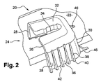
図2および3に図示したように、射出成形プラスチックのトリム部品20は、ほぼ平面的な表面を持つ。部品の表面は曲面でも良いが、実用的な理由から平面Sを基準平面として採用する。
As illustrated in FIGS. 2 and 3, the injection molded
トリム部品20は、例えば、自動車のドアに固定されることを意図したサイドトリムストライプである。
The
トリム部品20は、その内面22上に、締結クリップ(図示していない)を運ぶことを意図した中間面Pのブリッジ26からなる締結手段24を有する。
The
ブリッジ26は、中間面Pに対して互いに反対側の2つの側壁28を持つ。側壁28は,中間面Pおよび基準面Sに対して垂直な横断面Tにほぼ平行な方向を向く先端壁30によって互いに連結されている。ブリッジ26はU字型の輪郭であり、部品20の基準面Sにほぼ平行な壁部32は、側壁28および先端壁30に共に接続されている。壁部32は,クリップを受け入れることを意図した開口34を有する。
The
側壁28は、その外面36上に、平面Tと平行な横断面内に配向された互いに平行な多数のリブ38を持つ。
The
図3および4に図示しているように、それぞれのリブ38は,側壁28の先端部42に対して突出する先端40を持ち、前記先端部42は,クリップ支持壁32の反対側にある。側壁28の先端部42は、中間面Pにほぼ垂直な平面Rを画成する。
As shown in FIGS. 3 and 4, each
然しながら、図示しなかったその他の実施の形態においては、平面Rは中間面Pに垂直であることは出来ず、締結手段24が中間面Pに対して対称性を示すことはない。 However, in other embodiments not shown, the plane R cannot be perpendicular to the intermediate plane P and the fastening means 24 does not exhibit symmetry with respect to the intermediate plane P.
図3および5に図示するように、リブ38の端部40は、先端部42と部品20の内面22の間にスペース44が残されるような形で、部品20の内面22に接続されている。
As shown in FIGS. 3 and 5, the
リブ38は、三角形の内部に描くことが出来る輪郭を持ち、その三角形の1辺は部品20の内面22と接続している。
The
図4に図示されているように、部品20の内面22に接続されている領域ではリブ38の肉厚は薄い。従って、リブ38の内部46は、離型を容易にするために、切り欠き48を持つ。
As shown in FIG. 4, the
ブリッジ26は,従って、リブ38の先端部42によって形成された基本的に分離された接続領域のみによって、部品20の内面22と接続されている。
The
さらに、図2および3に図示するように、中間面Pと基準面Sとの交差によって画成される線に相当する方向での締結手段の剪断強度を改良するために、中間面Pにほぼ平行に配向された追加リブ46を,側壁28に連続して設けることができる。追加リブ46は先端壁32近辺に位置する。
2 and 3, in order to improve the shear strength of the fastening means in the direction corresponding to the line defined by the intersection of the intermediate plane P and the reference plane S,
部品の成型のためには、ブリッジ26の内部に挿入されることを目的とした「滑り充填部品」(図示していない)を有するモールド(図示していない)が必要である。
In order to mold the part, a mold (not shown) having a “slip filling part” (not shown) intended to be inserted into the
図3に示すように、充填部品をより容易に離型するため、側壁28の先端部42によって形成される平面Rは、部品20の基準面Sに対して角度αを持たせている。
As shown in FIG. 3, the plane R formed by the
さらに、リブ38は、充填部品を使用するよりも成形用キャビティによってパンチ成形された。このことは以下のような多くの利点を与える。
−ブリッジ26中に形成されたハウジング内の充填部品の載置される支持面がより大きく、射出成形圧と関連する変形を制限することができる。
−充填部品の引き出し応力が低いので、部品20を圧迫すること無く容易に離型出来る。
−リブ38により、充填部品が取り外される間、部品20をモールド内の所定位置に保持することができる。
Furthermore, the
-The support surface on which the filling parts in the housing formed in the
-Since the pull-out stress of the filling part is low, it can be easily released without pressing the
-The
従って、本発明によるトリム部品20は、例えばリップルマークや収縮マークといった欠陥ばかりで無く、充填部品の背後に現れる流れ跡といった外観上の欠陥が遙かに少ない。
Therefore, the
さらに、締結手段の引き抜き強さが改善されている。 Furthermore, the pulling strength of the fastening means is improved.
Claims (7)
基準面(S)に沿った方向を向いたほぼ平面の部分と、
少なくとも1つの締結手段(24)を備えた内面(22)と、
中間面(P)のブリッジ(26)で構成され、クリップを支持可能であり、かつ、中間面(P)に対して互いに反対で、クリップ支持壁(32)によって互いに連結された2つの側壁(28)を持つ締結手段(24)と、を備え、
ブリッジ(26)の側壁(28)は、その外面(36)にリブ(38)を有し、そのリブの一端(40)は、側壁(28)の先端部(42)によって画成される平面(R)に対して突起として伸び、その側壁(28)はクリップ支持壁(32)の反対端にあり、平面(R)とトリム部品(20)の内面(22)との間にスペース(44)を残すようにトリム部品(20)の内面(22)に接続されていることを特徴とするトリム部品。 An injection molded plastic trim part (20) comprising:
A substantially planar portion facing in a direction along the reference plane (S);
An inner surface (22) with at least one fastening means (24);
Two side walls (26) composed of a bridge (26) of the intermediate surface (P), capable of supporting the clip and connected to each other by a clip support wall (32) opposite to the intermediate surface (P) Fastening means (24) having 28),
The side wall (28) of the bridge (26) has a rib (38) on its outer surface (36), and one end (40) of the rib is a plane defined by the tip (42) of the side wall (28). (R) extends as a protrusion, its side wall (28) is at the opposite end of the clip support wall (32), and a space (44) between the plane (R) and the inner surface (22) of the trim part (20). The trim part is connected to the inner surface (22) of the trim part (20) so as to leave a).
Applications Claiming Priority (3)
| Application Number | Priority Date | Filing Date | Title |
|---|---|---|---|
| FR0951263A FR2942647B1 (en) | 2009-02-27 | 2009-02-27 | ASPECT PART COMPRISING FASTENING MEANS. |
| FR0951263 | 2009-02-27 | ||
| PCT/FR2010/050166 WO2010097531A1 (en) | 2009-02-27 | 2010-02-02 | Trim component comprising fastening means |
Publications (1)
| Publication Number | Publication Date |
|---|---|
| JP2012519103A true JP2012519103A (en) | 2012-08-23 |
Family
ID=41020904
Family Applications (1)
| Application Number | Title | Priority Date | Filing Date |
|---|---|---|---|
| JP2011551510A Withdrawn JP2012519103A (en) | 2009-02-27 | 2010-02-02 | Trim part having fastening means |
Country Status (9)
| Country | Link |
|---|---|
| US (1) | US20120001446A1 (en) |
| EP (1) | EP2401180B1 (en) |
| JP (1) | JP2012519103A (en) |
| KR (1) | KR20110122744A (en) |
| CN (1) | CN102333679A (en) |
| BR (1) | BRPI1008615A2 (en) |
| FR (1) | FR2942647B1 (en) |
| RU (1) | RU2011139306A (en) |
| WO (1) | WO2010097531A1 (en) |
Families Citing this family (3)
| Publication number | Priority date | Publication date | Assignee | Title |
|---|---|---|---|---|
| JP6052029B2 (en) * | 2013-04-04 | 2016-12-27 | トヨタ紡織株式会社 | Interior materials for vehicles |
| JP6104030B2 (en) * | 2013-04-19 | 2017-03-29 | 本田技研工業株式会社 | Vehicle back door structure |
| FR3019239B1 (en) * | 2014-03-31 | 2016-05-06 | Faurecia Interieur Ind | MOLDED PIECE WITH CLIP HOLDER, ASSEMBLY COMPRISING SUCH A PART, PROCESS FOR PRODUCING THE SAME |
Family Cites Families (8)
| Publication number | Priority date | Publication date | Assignee | Title |
|---|---|---|---|---|
| GB1056697A (en) * | 1964-06-16 | 1967-01-25 | Creators Ltd | Improvements in decorative plastics extrusions |
| US6805928B2 (en) * | 1999-05-12 | 2004-10-19 | Visteon System Interieurs | Decorative component for use as a piece of trim of a vehicle |
| US6276109B1 (en) * | 1999-12-20 | 2001-08-21 | General Motors Corporation | Motor vehicle trim panel assembly and method |
| FR2850066B1 (en) * | 2003-01-22 | 2005-03-11 | Rehau Sa | IMPROVED INTEGRATED FASTENING CLIP, IN PARTICULAR FOR AUTOMOTIVE CASE DRUMS |
| US6883847B2 (en) * | 2003-09-17 | 2005-04-26 | Schlegel Corporation | Carrierless flange cover with integral trim strip |
| JP5000226B2 (en) * | 2006-08-02 | 2012-08-15 | 大和化成工業株式会社 | clip |
| FR2911646B1 (en) * | 2007-01-18 | 2009-03-13 | Rehau Sa | FIXING CLIP WITH TWO HOLDING POSITIONS AND HINGED HEAD AND BODY STICK COMPRISING THE SAME |
| US7854101B2 (en) * | 2007-04-16 | 2010-12-21 | Honda Motor Co., Ltd | System for attaching components to a vehicle |
-
2009
- 2009-02-27 FR FR0951263A patent/FR2942647B1/en not_active Expired - Fee Related
-
2010
- 2010-02-02 CN CN2010800092732A patent/CN102333679A/en active Pending
- 2010-02-02 EP EP10708266A patent/EP2401180B1/en not_active Not-in-force
- 2010-02-02 US US13/203,394 patent/US20120001446A1/en not_active Abandoned
- 2010-02-02 KR KR1020117022117A patent/KR20110122744A/en not_active Application Discontinuation
- 2010-02-02 RU RU2011139306/11A patent/RU2011139306A/en unknown
- 2010-02-02 JP JP2011551510A patent/JP2012519103A/en not_active Withdrawn
- 2010-02-02 WO PCT/FR2010/050166 patent/WO2010097531A1/en active Application Filing
- 2010-02-02 BR BRPI1008615A patent/BRPI1008615A2/en not_active Application Discontinuation
Also Published As
| Publication number | Publication date |
|---|---|
| EP2401180B1 (en) | 2012-12-19 |
| EP2401180A1 (en) | 2012-01-04 |
| WO2010097531A1 (en) | 2010-09-02 |
| CN102333679A (en) | 2012-01-25 |
| FR2942647B1 (en) | 2011-02-11 |
| FR2942647A1 (en) | 2010-09-03 |
| KR20110122744A (en) | 2011-11-10 |
| US20120001446A1 (en) | 2012-01-05 |
| BRPI1008615A2 (en) | 2016-03-15 |
| RU2011139306A (en) | 2013-04-10 |
Similar Documents
| Publication | Publication Date | Title |
|---|---|---|
| JP5020237B2 (en) | Profile for fastening the cover to the support, especially the headrest of an automobile | |
| JP6581092B2 (en) | Spoiler for car tailgate | |
| JP5118632B2 (en) | Device for fixing decorative contours on molded bands | |
| US9440569B2 (en) | Vehicle seat and method of manufacturing the same | |
| CN104364143B (en) | The component for being used to form air guide element of motor vehicle | |
| JP5949283B2 (en) | Vehicle ceiling structure | |
| US20090007498A1 (en) | Weather strip | |
| JP5994646B2 (en) | Mounting structure for vehicle interior parts | |
| JP2012519103A (en) | Trim part having fastening means | |
| JP2009034872A (en) | Plastic molding with hinge | |
| JP2017537026A (en) | Grazing unit having shape steel joint, trim and core, and method for producing glazing unit | |
| USD598351S1 (en) | Molding for sealing a motor vehicle windshield panel with a cowl panel | |
| USD598352S1 (en) | Trim molding for a motor vehicle window | |
| JP5590311B2 (en) | Door trim | |
| CN103204112A (en) | Installation structure of interior component and instrument board structure | |
| CN210852296U (en) | Suitcase carpet structure and car | |
| JP2018096065A (en) | Curing material for opening frame | |
| JP2003063321A (en) | Exterior part for vehicle | |
| JP5009863B2 (en) | Sensor protector | |
| JP2004090680A (en) | Car door structure | |
| JP4666582B2 (en) | Automotive interior parts | |
| US7690907B2 (en) | Multi-film junction structure | |
| JP2009079612A (en) | Mounting structure in resin molding | |
| JP3426210B2 (en) | Long molded products with decorative strips | |
| WO2019087230A1 (en) | Automobile molding |
Legal Events
| Date | Code | Title | Description |
|---|---|---|---|
| A300 | Application deemed to be withdrawn because no request for examination was validly filed |
Free format text: JAPANESE INTERMEDIATE CODE: A300 Effective date: 20130402 |