JP2012508890A - Sample or sample component analysis system and methods for making and using the system - Google Patents
Sample or sample component analysis system and methods for making and using the system Download PDFInfo
- Publication number
- JP2012508890A JP2012508890A JP2011536516A JP2011536516A JP2012508890A JP 2012508890 A JP2012508890 A JP 2012508890A JP 2011536516 A JP2011536516 A JP 2011536516A JP 2011536516 A JP2011536516 A JP 2011536516A JP 2012508890 A JP2012508890 A JP 2012508890A
- Authority
- JP
- Japan
- Prior art keywords
- sample
- light source
- light
- detection
- excimer
- Prior art date
- Legal status (The legal status is an assumption and is not a legal conclusion. Google has not performed a legal analysis and makes no representation as to the accuracy of the status listed.)
- Pending
Links
- 238000000034 method Methods 0.000 title claims abstract description 28
- 238000004458 analytical method Methods 0.000 title abstract description 21
- 238000001514 detection method Methods 0.000 claims description 113
- 230000005284 excitation Effects 0.000 claims description 46
- 230000003647 oxidation Effects 0.000 claims description 40
- 238000007254 oxidation reaction Methods 0.000 claims description 40
- 239000007789 gas Substances 0.000 claims description 37
- 238000002485 combustion reaction Methods 0.000 claims description 34
- 230000001590 oxidative effect Effects 0.000 claims description 30
- IJGRMHOSHXDMSA-UHFFFAOYSA-N Atomic nitrogen Chemical compound N#N IJGRMHOSHXDMSA-UHFFFAOYSA-N 0.000 claims description 28
- NINIDFKCEFEMDL-UHFFFAOYSA-N Sulfur Chemical compound [S] NINIDFKCEFEMDL-UHFFFAOYSA-N 0.000 claims description 28
- 239000011593 sulfur Substances 0.000 claims description 28
- 229910052717 sulfur Inorganic materials 0.000 claims description 28
- 239000007800 oxidant agent Substances 0.000 claims description 21
- RAHZWNYVWXNFOC-UHFFFAOYSA-N Sulphur dioxide Chemical compound O=S=O RAHZWNYVWXNFOC-UHFFFAOYSA-N 0.000 claims description 20
- 238000012545 processing Methods 0.000 claims description 18
- 239000000203 mixture Substances 0.000 claims description 17
- 230000003287 optical effect Effects 0.000 claims description 15
- 229910052757 nitrogen Inorganic materials 0.000 claims description 14
- 238000004891 communication Methods 0.000 claims description 13
- 238000000926 separation method Methods 0.000 claims description 12
- 238000010521 absorption reaction Methods 0.000 claims description 11
- 230000008859 change Effects 0.000 claims description 8
- 238000005070 sampling Methods 0.000 claims description 8
- 238000002347 injection Methods 0.000 claims description 7
- 239000007924 injection Substances 0.000 claims description 7
- 238000004128 high performance liquid chromatography Methods 0.000 claims description 5
- 238000012937 correction Methods 0.000 claims description 4
- 230000008569 process Effects 0.000 claims description 4
- 238000012795 verification Methods 0.000 claims description 4
- 238000003820 Medium-pressure liquid chromatography Methods 0.000 claims description 3
- 150000001875 compounds Chemical class 0.000 claims description 3
- 238000001962 electrophoresis Methods 0.000 claims description 3
- 238000003819 low-pressure liquid chromatography Methods 0.000 claims description 3
- XLYOFNOQVPJJNP-UHFFFAOYSA-N water Substances O XLYOFNOQVPJJNP-UHFFFAOYSA-N 0.000 claims description 3
- 239000000126 substance Substances 0.000 claims description 2
- 239000000446 fuel Substances 0.000 claims 4
- 239000004215 Carbon black (E152) Substances 0.000 claims 2
- 229930195733 hydrocarbon Natural products 0.000 claims 2
- 150000002430 hydrocarbons Chemical class 0.000 claims 2
- JWNBYUSSORDWOT-UHFFFAOYSA-N [Kr]Cl Chemical compound [Kr]Cl JWNBYUSSORDWOT-UHFFFAOYSA-N 0.000 claims 1
- 230000005540 biological transmission Effects 0.000 claims 1
- 239000002131 composite material Substances 0.000 claims 1
- 239000002283 diesel fuel Substances 0.000 claims 1
- 238000007599 discharging Methods 0.000 claims 1
- 239000003502 gasoline Substances 0.000 claims 1
- 239000003350 kerosene Substances 0.000 claims 1
- 239000000523 sample Substances 0.000 claims 1
- 238000006243 chemical reaction Methods 0.000 description 27
- CBENFWSGALASAD-UHFFFAOYSA-N Ozone Chemical compound [O-][O+]=O CBENFWSGALASAD-UHFFFAOYSA-N 0.000 description 24
- 238000001917 fluorescence detection Methods 0.000 description 24
- 230000004888 barrier function Effects 0.000 description 16
- 230000000875 corresponding effect Effects 0.000 description 13
- 229910052751 metal Inorganic materials 0.000 description 10
- 239000002184 metal Substances 0.000 description 10
- 238000004587 chromatography analysis Methods 0.000 description 7
- 238000001228 spectrum Methods 0.000 description 7
- 238000000862 absorption spectrum Methods 0.000 description 6
- 230000003750 conditioning effect Effects 0.000 description 6
- 239000004020 conductor Substances 0.000 description 6
- 229910052743 krypton Inorganic materials 0.000 description 6
- DNNSSWSSYDEUBZ-UHFFFAOYSA-N krypton atom Chemical compound [Kr] DNNSSWSSYDEUBZ-UHFFFAOYSA-N 0.000 description 6
- 239000012491 analyte Substances 0.000 description 5
- 230000006870 function Effects 0.000 description 5
- 238000005259 measurement Methods 0.000 description 5
- 239000007787 solid Substances 0.000 description 5
- VEXZGXHMUGYJMC-UHFFFAOYSA-M Chloride anion Chemical compound [Cl-] VEXZGXHMUGYJMC-UHFFFAOYSA-M 0.000 description 4
- 230000007423 decrease Effects 0.000 description 4
- 238000001914 filtration Methods 0.000 description 4
- 230000006872 improvement Effects 0.000 description 4
- 239000000463 material Substances 0.000 description 4
- 230000010355 oscillation Effects 0.000 description 4
- 230000002093 peripheral effect Effects 0.000 description 4
- 239000011701 zinc Substances 0.000 description 4
- HCHKCACWOHOZIP-UHFFFAOYSA-N Zinc Chemical compound [Zn] HCHKCACWOHOZIP-UHFFFAOYSA-N 0.000 description 3
- QVGXLLKOCUKJST-UHFFFAOYSA-N atomic oxygen Chemical compound [O] QVGXLLKOCUKJST-UHFFFAOYSA-N 0.000 description 3
- 238000011088 calibration curve Methods 0.000 description 3
- 238000002038 chemiluminescence detection Methods 0.000 description 3
- 230000001276 controlling effect Effects 0.000 description 3
- 238000013461 design Methods 0.000 description 3
- 229910052753 mercury Inorganic materials 0.000 description 3
- 229910052760 oxygen Inorganic materials 0.000 description 3
- 239000001301 oxygen Substances 0.000 description 3
- 238000011144 upstream manufacturing Methods 0.000 description 3
- 229910052725 zinc Inorganic materials 0.000 description 3
- ZAMOUSCENKQFHK-UHFFFAOYSA-N Chlorine atom Chemical compound [Cl] ZAMOUSCENKQFHK-UHFFFAOYSA-N 0.000 description 2
- 101000809261 Homo sapiens Ubiquitin carboxyl-terminal hydrolase 11 Proteins 0.000 description 2
- MWUXSHHQAYIFBG-UHFFFAOYSA-N Nitric oxide Chemical compound O=[N] MWUXSHHQAYIFBG-UHFFFAOYSA-N 0.000 description 2
- 102100038462 Ubiquitin carboxyl-terminal hydrolase 11 Human genes 0.000 description 2
- 229910052793 cadmium Inorganic materials 0.000 description 2
- BDOSMKKIYDKNTQ-UHFFFAOYSA-N cadmium atom Chemical compound [Cd] BDOSMKKIYDKNTQ-UHFFFAOYSA-N 0.000 description 2
- 239000003990 capacitor Substances 0.000 description 2
- 230000015556 catabolic process Effects 0.000 description 2
- 239000000460 chlorine Substances 0.000 description 2
- 229910052801 chlorine Inorganic materials 0.000 description 2
- 239000011261 inert gas Substances 0.000 description 2
- QSHDDOUJBYECFT-UHFFFAOYSA-N mercury Chemical compound [Hg] QSHDDOUJBYECFT-UHFFFAOYSA-N 0.000 description 2
- 230000004044 response Effects 0.000 description 2
- 230000003595 spectral effect Effects 0.000 description 2
- 238000012360 testing method Methods 0.000 description 2
- 238000000825 ultraviolet detection Methods 0.000 description 2
- YZCKVEUIGOORGS-OUBTZVSYSA-N Deuterium Chemical compound [2H] YZCKVEUIGOORGS-OUBTZVSYSA-N 0.000 description 1
- 230000032683 aging Effects 0.000 description 1
- 230000003321 amplification Effects 0.000 description 1
- 230000002596 correlated effect Effects 0.000 description 1
- 230000006378 damage Effects 0.000 description 1
- 229910052805 deuterium Inorganic materials 0.000 description 1
- 238000010586 diagram Methods 0.000 description 1
- 238000000295 emission spectrum Methods 0.000 description 1
- 230000005281 excited state Effects 0.000 description 1
- 238000001506 fluorescence spectroscopy Methods 0.000 description 1
- 238000004817 gas chromatography Methods 0.000 description 1
- 230000002452 interceptive effect Effects 0.000 description 1
- 239000007788 liquid Substances 0.000 description 1
- 238000012423 maintenance Methods 0.000 description 1
- -1 mercury halide Chemical class 0.000 description 1
- 238000012986 modification Methods 0.000 description 1
- 230000004048 modification Effects 0.000 description 1
- 239000006199 nebulizer Substances 0.000 description 1
- 238000003199 nucleic acid amplification method Methods 0.000 description 1
- 238000004904 shortening Methods 0.000 description 1
- 239000007921 spray Substances 0.000 description 1
- 238000002211 ultraviolet spectrum Methods 0.000 description 1
- 229910052724 xenon Inorganic materials 0.000 description 1
- FHNFHKCVQCLJFQ-UHFFFAOYSA-N xenon atom Chemical compound [Xe] FHNFHKCVQCLJFQ-UHFFFAOYSA-N 0.000 description 1
Images


Classifications
-
- G—PHYSICS
- G01—MEASURING; TESTING
- G01J—MEASUREMENT OF INTENSITY, VELOCITY, SPECTRAL CONTENT, POLARISATION, PHASE OR PULSE CHARACTERISTICS OF INFRARED, VISIBLE OR ULTRAVIOLET LIGHT; COLORIMETRY; RADIATION PYROMETRY
- G01J3/00—Spectrometry; Spectrophotometry; Monochromators; Measuring colours
- G01J3/02—Details
- G01J3/10—Arrangements of light sources specially adapted for spectrometry or colorimetry
-
- G—PHYSICS
- G01—MEASURING; TESTING
- G01N—INVESTIGATING OR ANALYSING MATERIALS BY DETERMINING THEIR CHEMICAL OR PHYSICAL PROPERTIES
- G01N21/00—Investigating or analysing materials by the use of optical means, i.e. using sub-millimetre waves, infrared, visible or ultraviolet light
- G01N21/17—Systems in which incident light is modified in accordance with the properties of the material investigated
- G01N21/25—Colour; Spectral properties, i.e. comparison of effect of material on the light at two or more different wavelengths or wavelength bands
- G01N21/27—Colour; Spectral properties, i.e. comparison of effect of material on the light at two or more different wavelengths or wavelength bands using photo-electric detection ; circuits for computing concentration
- G01N21/274—Calibration, base line adjustment, drift correction
-
- G—PHYSICS
- G01—MEASURING; TESTING
- G01N—INVESTIGATING OR ANALYSING MATERIALS BY DETERMINING THEIR CHEMICAL OR PHYSICAL PROPERTIES
- G01N21/00—Investigating or analysing materials by the use of optical means, i.e. using sub-millimetre waves, infrared, visible or ultraviolet light
- G01N21/62—Systems in which the material investigated is excited whereby it emits light or causes a change in wavelength of the incident light
- G01N21/63—Systems in which the material investigated is excited whereby it emits light or causes a change in wavelength of the incident light optically excited
- G01N21/64—Fluorescence; Phosphorescence
- G01N21/645—Specially adapted constructive features of fluorimeters
-
- G—PHYSICS
- G01—MEASURING; TESTING
- G01N—INVESTIGATING OR ANALYSING MATERIALS BY DETERMINING THEIR CHEMICAL OR PHYSICAL PROPERTIES
- G01N33/00—Investigating or analysing materials by specific methods not covered by groups G01N1/00 - G01N31/00
- G01N33/0004—Gaseous mixtures, e.g. polluted air
- G01N33/0009—General constructional details of gas analysers, e.g. portable test equipment
- G01N33/0027—General constructional details of gas analysers, e.g. portable test equipment concerning the detector
- G01N33/0036—General constructional details of gas analysers, e.g. portable test equipment concerning the detector specially adapted to detect a particular component
- G01N33/0042—SO2 or SO3
-
- G—PHYSICS
- G01—MEASURING; TESTING
- G01J—MEASUREMENT OF INTENSITY, VELOCITY, SPECTRAL CONTENT, POLARISATION, PHASE OR PULSE CHARACTERISTICS OF INFRARED, VISIBLE OR ULTRAVIOLET LIGHT; COLORIMETRY; RADIATION PYROMETRY
- G01J3/00—Spectrometry; Spectrophotometry; Monochromators; Measuring colours
- G01J3/28—Investigating the spectrum
- G01J3/44—Raman spectrometry; Scattering spectrometry ; Fluorescence spectrometry
- G01J3/4406—Fluorescence spectrometry
-
- G—PHYSICS
- G01—MEASURING; TESTING
- G01N—INVESTIGATING OR ANALYSING MATERIALS BY DETERMINING THEIR CHEMICAL OR PHYSICAL PROPERTIES
- G01N21/00—Investigating or analysing materials by the use of optical means, i.e. using sub-millimetre waves, infrared, visible or ultraviolet light
- G01N21/75—Systems in which material is subjected to a chemical reaction, the progress or the result of the reaction being investigated
- G01N21/76—Chemiluminescence; Bioluminescence
-
- G—PHYSICS
- G01—MEASURING; TESTING
- G01N—INVESTIGATING OR ANALYSING MATERIALS BY DETERMINING THEIR CHEMICAL OR PHYSICAL PROPERTIES
- G01N2201/00—Features of devices classified in G01N21/00
- G01N2201/06—Illumination; Optics
- G01N2201/061—Sources
- G01N2201/06113—Coherent sources; lasers
Landscapes
- Physics & Mathematics (AREA)
- Health & Medical Sciences (AREA)
- Chemical & Material Sciences (AREA)
- Spectroscopy & Molecular Physics (AREA)
- General Physics & Mathematics (AREA)
- Life Sciences & Earth Sciences (AREA)
- General Health & Medical Sciences (AREA)
- Analytical Chemistry (AREA)
- Biochemistry (AREA)
- Engineering & Computer Science (AREA)
- Immunology (AREA)
- Pathology (AREA)
- Combustion & Propulsion (AREA)
- Food Science & Technology (AREA)
- Medicinal Chemistry (AREA)
- Nuclear Medicine, Radiotherapy & Molecular Imaging (AREA)
- Mathematical Physics (AREA)
- Theoretical Computer Science (AREA)
- Investigating, Analyzing Materials By Fluorescence Or Luminescence (AREA)
Abstract
【構成】光源によって励起されたときに蛍光を発光できる種を含有するサンプルまたはサンプル成分を分析する分析システムおよび分析方法である。ここで使用する光源は、電圧/電流調整回路を持つ高電圧電源を備えたエキシマー光源からなる。
【選択図】図2AAn analysis system and method for analyzing a sample or sample component containing a species capable of emitting fluorescence when excited by a light source. The light source used here is an excimer light source provided with a high voltage power source having a voltage / current adjustment circuit.
[Selection] Figure 2A
Description
本発明は、蛍光検出サブシステムを有するサンプルまたはサンプル成分の分析システムまたは分析装置、およびこれらの製造方法および使用方法に関する。 The present invention relates to a sample or sample component analysis system or apparatus having a fluorescence detection subsystem and methods for making and using them.
より具体的には、本発明はサンプルまたはサンプル成分の分析システムまたは分析装置、およびこれらの製造方法および使用方法であって、実施態様にもよるが、高電圧、高周波電流および電圧制御式電源を有する蛍光検出サブシステム、ソフトウェア検出補正装置およびエキシマー光源またはランプを有する光源を備えた上記システムに関する。 More specifically, the present invention relates to a sample or sample component analysis system or apparatus, and methods for making and using the same, depending on the embodiment, including high voltage, high frequency current and voltage controlled power supplies. Fluorescence detection subsystem, software detection and correction apparatus, and an excimer light source or a light source having a lamp.
紫外線蛍光は、サンプルの硫黄分を検出し、定量化するために利用されている一般的な技術である。最新の蛍光器具の場合、サンプルと相互作用する光の狭い波長帯または周波数帯を対象として設計されたフィルターを備えたブロードなスペクトル光源を利用している。一般的に、光は光チャンバー内のサンプルまたはサンプル成分中の蛍光活性化合物と相互作用する。なお、サンプルはサンプルループを介して、あるいはクロマトグラフィーカラムから光チャンバーに直接供給できる。 Ultraviolet fluorescence is a common technique used to detect and quantify the sulfur content of a sample. Modern fluorescent instruments utilize a broad spectral light source with a filter designed for a narrow wavelength band or frequency band of light that interacts with the sample. In general, light interacts with a fluorescently active compound in a sample or sample component in a light chamber. The sample can be supplied directly to the light chamber through a sample loop or from a chromatography column.
ブロードなスペクトル光源のほかに、光源には原子蒸気ランプも利用されている。これらランプは波長帯または周波数帯がより狭く、フィルター機能はそれほど必要ないが、これらランプは光出力が経時的に一定の割合で小さくなる傾向がある。このような経時的な光出力低下は、結果的にシステム装置の安定性に関する、またシステム装置の検出限界に関する問題を生じる。紫外線蛍光検出の場合、亜鉛ランプ、カドミウムランプやその他の金属ランプが光源として利用されている。ところが、これらランプの多くは、SO2の紫外線蛍光検出などのある種の検出のためには最適とはいえない光を発光する。SO2は約190nmと約230nmとの間にある紫外光を吸収する。NOもこの帯域にある紫外光を吸収するが、NO吸収スペクトルは、約215nmと約225nmとの間に(光を吸収しない)ギャップをもつ。亜鉛ランプは220nmに中心をもつ光を発光するが、フィルターにかけても発光光は220nmよりも広く、SO2検出に干渉するNOを励起できる光を含む。 In addition to broad spectrum light sources, atomic vapor lamps are also used as light sources. These lamps have a narrower wavelength band or frequency band and require less filter function, but these lamps tend to have a light output that decreases at a constant rate over time. Such a decrease in light output over time results in problems relating to the stability of the system device and the detection limits of the system device. In the case of ultraviolet fluorescence detection, zinc lamps, cadmium lamps and other metal lamps are used as light sources. However, many of these lamps, for certain detection of such UV fluorescence detection SO 2 emits light less than optimal. SO 2 absorbs ultraviolet light that is between about 190 nm and about 230 nm. NO also absorbs ultraviolet light in this band, but the NO absorption spectrum has a gap (does not absorb light) between about 215 nm and about 225 nm. The zinc lamp emits light having a center at 220 nm, but the emitted light is wider than 220 nm even when applied to the filter, and includes light capable of exciting NO that interferes with SO 2 detection.
USP7,268,355には、光源として特別に設計されたエキシマーランプを使用した紫外線蛍光装置が開示されている。このランプの場合、クリプトン/塩素混合物を利用して、約222nmに中心がある狭い波長帯の光を発光する。 USP 7,268,355 discloses an ultraviolet fluorescent device using an excimer lamp specially designed as a light source. In this lamp, a krypton / chlorine mixture is used to emit light in a narrow wavelength band centered at about 222 nm.
分析機器を使用対象とするエキシマー光源またはランプが開示されているが、当業界において紫外線蛍光機器を使用対象としたエキシマー光源またはランプの改良が必要である。特に、これは、電圧/電流制御サブシステムおよび/またはソフトウェア検出信号調整サブシステムを備えたエキシマー光源またはランプなどの蛍光光源を備え、安定性および信頼性を改善し、かつ全硫黄分および/または全窒素分の検出レベルを低く設定した分析機器についていえる。 Although excimer light sources or lamps intended for use with analytical instruments are disclosed, improvements in excimer light sources or lamps intended for use with ultraviolet fluorescent instruments are needed in the industry. In particular, it comprises a fluorescent light source such as an excimer light source or lamp with a voltage / current control subsystem and / or a software detection signal conditioning subsystem, which improves stability and reliability, and total sulfur content and / or This is true for analytical instruments with a low detection level of total nitrogen.
本発明の実施態様は、サンプル供給搬送サブシステム、場合に応じて設けられる酸化処理サブシステム、検出サブシステムおよび分析素子サブシステムを備えた、サンプルまたはサンプル成分の分析システムまたは分析装置を提供するものである。サンプル供給搬送サブシステムは、直接注入装置、サンプルループ装置、インライン式サンプリング装置、クロマトグラフィーユニット(例えば、GC、LC、HPLCなど)またはその他のサンプル分離ユニットで構成できる。酸化処理サブシステムは、酸化処理域をもつ燃焼管を備え、この酸化処理域内で、すべての酸化性サンプル成分を対応する酸化物にほぼ完全に転換できる。検出サブシステムは電流および電圧をタイトに制御できる高周波/高電圧電源を備えた光源、場合に応じて設けられるソフトウェア検出信号調整サブシステム、検出チャンバー、および検出素子を備える。分析素子サブシステムは、一般的にいって、(コンピュータを使用できる)デジタル処理ユニット、メモリー、表示素子、印刷素子、大容量記憶素子、通信ハードウェア/ソフトウェア、他の公知周辺素子、および検出素子信号を受信分析するソフトウェアを備える。光源としては、金属蒸気ランプ、ガスランプまたは他のブロードスペクトル光源などのフィルター処理式ブロードスペクトル光源、フィルター処理式または非フィルター処理式エキシマー光源、あるいはフィルター処理式または非フィルター処理式レーザー光源を使用できる。 Embodiments of the present invention provide a sample or sample component analysis system or analyzer comprising a sample supply and transport subsystem, an optional oxidation subsystem, a detection subsystem and an analytical element subsystem. It is. The sample supply and transport subsystem can consist of a direct injection device, a sample loop device, an in-line sampling device, a chromatography unit (eg, GC, LC, HPLC, etc.) or other sample separation unit. The oxidation processing subsystem comprises a combustion tube with an oxidation treatment zone within which all oxidizable sample components can be almost completely converted to the corresponding oxide. The detection subsystem includes a light source with a high-frequency / high-voltage power supply capable of tightly controlling current and voltage, a software detection signal adjustment subsystem provided in some cases, a detection chamber, and a detection element. Analytical element subsystems generally include digital processing units (which can use a computer), memory, display elements, printing elements, mass storage elements, communication hardware / software, other known peripheral elements, and detection elements. Software for receiving and analyzing signals is provided. The light source can be a filtered broad spectrum light source such as a metal vapor lamp, gas lamp or other broad spectrum light source, a filtered or non-filtered excimer light source, or a filtered or non-filtered laser light source .
また、本発明の実施態様は、サンプル供給搬送サブシステム、酸化処理サブシステム、検出サブシステム、および分析素子サブシステムを備えた、サンプルまたはサンプル成分の分析システムまたは分析装置を提供するものである。サンプル供給搬送サブシステムは直接注入装置、サンプルループ装置、インライン式サンプリング装置、クロマトグラフィーユニット(例えば、GC、LC、HPLCなど)またはその他のサンプル分離ユニットで構成できる。酸化処理サブシステムは、酸化処理域をもつ燃焼管を備え、この酸化処理域内で、すべての酸化性サンプル成分を対応する酸化物にほぼ完全に転換できる。検出サブシステムは電流および電圧をタイトに制御できる高周波電源を備えた光源、場合に応じて設けられるソフトウェア検出信号調整サブシステム、検出チャンバー、および検出素子を備える。分析素子サブシステムは、一般的にいって、(コンピュータを使用できる)デジタル処理ユニット、メモリー、表示素子、印刷素子、大容量記憶素子、通信ハードウェア/ソフトウェア、他の公知周辺素子、および検出素子信号を受信分析するソフトウェアを備える。光源としては、金属蒸気ランプ、ガスランプまたは他のブロードスペクトル光源などのフィルター処理式ブロードスペクトル光源、フィルター処理式または非フィルター処理式エキシマー光源、あるいはフィルター処理式または非フィルター処理式レーザー光源を使用できる。 Embodiments of the present invention also provide a sample or sample component analysis system or apparatus comprising a sample supply and transport subsystem, an oxidation treatment subsystem, a detection subsystem, and an analytical element subsystem. The sample supply and transport subsystem can consist of a direct injection device, a sample loop device, an inline sampling device, a chromatography unit (eg, GC, LC, HPLC, etc.) or other sample separation unit. The oxidation processing subsystem comprises a combustion tube with an oxidation treatment zone within which all oxidizable sample components can be almost completely converted to the corresponding oxide. The detection subsystem includes a light source having a high-frequency power source capable of tightly controlling current and voltage, a software detection signal adjustment subsystem provided in some cases, a detection chamber, and a detection element. Analytical element subsystems generally include digital processing units (which can use a computer), memory, display elements, printing elements, mass storage elements, communication hardware / software, other known peripheral elements, and detection elements. Software for receiving and analyzing signals is provided. The light source can be a filtered broad spectrum light source such as a metal vapor lamp, gas lamp or other broad spectrum light source, a filtered or non-filtered excimer light source, or a filtered or non-filtered laser light source .
また、本発明の実施態様は、本発明システムにサンプルを供給するステップを有するサンプルまたはサンプル成分の分析方法を提供する。この分析方法は、サンプルを成分に分離するステップを有していてもよい。さらに、蛍光検出に先立ってサンプルまたはサンプル成分を対応する酸化物に酸化するステップを有していてもよい。サンプルまたはサンプル成分が適正な検出状態になったなら、サンプルまたはサンプル成分を検出サブシステムに送り出し、ここでサンプルまたはサンプル成分が蛍光反応チャンバーに流入し、光源から光を吸収する。サンプルまたはサンプル成分の一部が、励起サンプルまたは励起サンプル成分に転換する。励起サンプルまたは励起サンプル成分の一部が蛍光発光し、蛍光の一部が光反応チャンバーから出、検出素子入口から検出素子に流入する。検出素子では、検出素子に流入する多数の光子(蛍光強度)が比例電気信号に転換する。次にこの電気信号が分析装置で分析され、そしてサンプルまたはサンプル成分の蛍光活性種の濃度に関連付けられ、即ちサンプルまたはサンプル成分の硫黄、窒素などの原子種の濃度に関連付けられる。光源としては、金属蒸気ランプ、ガスランプまたは他のブロードスペクトル光源などのフィルター処理式ブロードスペクトル光源、フィルター処理式または非フィルター処理式エキシマー光源、あるいはフィルター処理式または非フィルター処理式レーザー光源を使用できる。 Embodiments of the present invention also provide a method for analyzing a sample or sample component comprising providing a sample to the system of the present invention. The analysis method may include a step of separating the sample into components. In addition, the method may include oxidizing the sample or sample component to the corresponding oxide prior to fluorescence detection. Once the sample or sample component is in the proper detection state, the sample or sample component is delivered to the detection subsystem, where the sample or sample component flows into the fluorescence reaction chamber and absorbs light from the light source. A portion of the sample or sample component is converted to an excited sample or excited sample component. Part of the excitation sample or excitation sample component emits fluorescence, and part of the fluorescence exits the photoreaction chamber and flows into the detection element from the detection element inlet. In the detection element, a large number of photons (fluorescence intensity) flowing into the detection element are converted into proportional electric signals. This electrical signal is then analyzed by the analyzer and correlated to the concentration of fluorescent active species in the sample or sample component, i.e., related to the concentration of atomic species such as sulfur, nitrogen, etc. in the sample or sample component. The light source can be a filtered broad spectrum light source such as a metal vapor lamp, gas lamp or other broad spectrum light source, a filtered or non-filtered excimer light source, or a filtered or non-filtered laser light source .
例えば、蛍光活性種が二酸化硫黄(SO2)の場合には、電気信号は光反応チャンバーの二酸化硫黄の量に比例し、即ちサンプルまたはサンプル成分の硫黄量に比例する。二つ以上のサンプル成分が硫黄を含有する場合、硫黄を含有する各成分の硫黄濃度の合計がサンプル中の全硫黄分になる。サンプルが成分として二酸化硫黄を含有する場合、電気信号はサンプルの硫黄濃度に正比例する。元のサンプルが化学結合硫黄か、あるいは二酸化硫黄と化学結合硫黄の組み合わせを含有する場合、酸化処理サブシステムを含むサブシステムで化学結合硫黄を二酸化硫黄に転換する。サンプルが化学結合窒素を含有する場合、オゾン誘導化学発光サブシステムによってNOを決定できる。実施態様にもよるが、NO化学発光は紫外線検出サブシステムの上流側で行う。 For example, if the fluorescently active species is sulfur dioxide (SO 2 ), the electrical signal is proportional to the amount of sulfur dioxide in the photoreaction chamber, ie proportional to the amount of sulfur in the sample or sample component. When two or more sample components contain sulfur, the total sulfur concentration of each component containing sulfur is the total sulfur content in the sample. If the sample contains sulfur dioxide as a component, the electrical signal is directly proportional to the sulfur concentration of the sample. If the original sample contains chemically bound sulfur or a combination of sulfur dioxide and chemically bound sulfur, the chemically bound sulfur is converted to sulfur dioxide in a subsystem that includes an oxidation treatment subsystem. If the sample contains chemically bound nitrogen, NO can be determined by the ozone-induced chemiluminescence subsystem. Depending on the embodiment, NO chemiluminescence occurs upstream of the UV detection subsystem.
また、本発明は、サンプルを各成分に分離する条件でサンプルをサンプル供給搬送システムから分離ユニットに供給するステップを有するクロマトグラフィー分析方法を提供するものでもある。分離後、サンプル成分を検出装置に送る。場合にもよるが、燃焼装置で最初に各成分を酸化処理してもよい。検出装置では、光反応チャンバーの光源(実施態様にもよるが、光源またはランプ)からの光に各成分を接触させる。ここで蛍光活性種の一部が励起し、励起種の一部が蛍光発光する。蛍光の一部がチャンバーを出、検出素子入口から検出素子に入り、電気信号が出力する。この電気信号が蛍光活性種の濃度に転換し、即ちサンプルの硫黄や窒素などの対象となる対応する原子成分の濃度に転換する。活性種が二酸化硫黄の場合、分析素子が、各成分の硫黄濃度およびサンプルの全硫黄濃度を出力する。光源としては、金属蒸気ランプ、ガスランプまたは他のブロードスペクトル光源などのフィルター処理式ブロードスペクトル光源、フィルター処理式または非フィルター処理式エキシマー光源、あるいはフィルター処理式または非フィルター処理式レーザー光源を使用できる。 The present invention also provides a chromatographic analysis method including a step of supplying a sample from a sample supply and transportation system to a separation unit under conditions for separating the sample into components. After separation, the sample components are sent to a detection device. Depending on the case, each component may be oxidized first in the combustion apparatus. In the detection apparatus, each component is brought into contact with light from a light source (a light source or a lamp, depending on the embodiment) of the photoreaction chamber. Here, a part of the fluorescent active species is excited, and a part of the excited species emits fluorescence. A part of the fluorescence exits the chamber, enters the detection element from the detection element inlet, and outputs an electrical signal. This electrical signal is converted to the concentration of the fluorescent active species, that is, to the concentration of the corresponding atomic component of interest such as sulfur or nitrogen in the sample. When the active species is sulfur dioxide, the analysis element outputs the sulfur concentration of each component and the total sulfur concentration of the sample. The light source can be a filtered broad spectrum light source such as a metal vapor lamp, gas lamp or other broad spectrum light source, a filtered or non-filtered excimer light source, or a filtered or non-filtered laser light source .
添付図面を参照して以下の詳細な説明を読めば、本発明をよりよく理解できるはずである。なお、同じ要素は同じ符号で示す。 The invention will be better understood on reading the following detailed description with reference to the accompanying drawings. In addition, the same element is shown with the same code | symbol.
本発明者の知見によれば、サンプルまたはサンプル成分の分析装置または分析システムは、他の潜在的な緩衝化合物を励起することなく、蛍光活性アナライト(被分析体)を選択的に分析できる波長に中心設定したきわめて狭い波長域(場合によって、近単色域)の光を発光するように特に設定されたエキシマー光源を利用して構成できる。例えば、SO2蛍光検出に緩衝する種であるNOの励起を最小限に抑制した状態でSO2を選択的に励起する光源を利用した、硫黄分または全硫黄分の分析装置である。また本発明者の知見によれば、分析システムは、機器安定性および機器信頼性を改善し、光源が設計されたアナライト(analyte)の検出限界を下げるソフトウェア検出信号調整サブシステムを備えることができる。本発明者のさらに別な知見によれば、このソフトウェア検出信号調整サブシステムは、エキシマー光源を備えた任意の光源と併用できる。例えば、アナライトが二酸化硫黄の場合、光源としては中心が厳密に222nm付近に設定された光を発光しなければならない。エキシマー光源の場合、約222nmに中心が設定された光を発光できるガス混合体を利用する。他の蛍光活性種を分析対象とする場合、エキシマー光源は、上記種の吸収スペクトル内の波長に中心設定された光を発光できるガス混合体を利用する。 According to the inventor's knowledge, a sample or sample component analyzer or analysis system can selectively analyze a fluorescently active analyte (analyte) without exciting other potential buffer compounds. An excimer light source that is specifically set to emit light in a very narrow wavelength range (in some cases, a near monochromatic range) centered on the light source can be used. For example, a sulfur or total sulfur analyzer using a light source that selectively excites SO 2 in a state where excitation of NO, which is a species buffered for SO 2 fluorescence detection, is suppressed to a minimum. Also, according to the inventor's knowledge, the analysis system may include a software detection signal adjustment subsystem that improves instrument stability and instrument reliability and lowers the detection limit of the analyte for which the light source is designed. it can. According to further knowledge of the inventor, this software detection signal conditioning subsystem can be used in conjunction with any light source with an excimer light source. For example, when the analyte is sulfur dioxide, the light source must emit light whose center is strictly set around 222 nm. In the case of an excimer light source, a gas mixture capable of emitting light whose center is set at about 222 nm is used. When other fluorescently active species are to be analyzed, the excimer light source utilizes a gas mixture that can emit light centered at a wavelength within the absorption spectrum of the species.
蛍光検出および化学発光の上記以外の細部については、以下の特許文献(いずれもアメリカ特許又はアメリカ特許出願)が参考になる。USP4904606、4914037、4916077、4950456,5916523、6075609、6143245、6458328、6636314、7018845、7244395、7291203、10/970686、10/970353、11/949610、11/834495、11/834509および11/834514。いずれも本開示に援用するものである。これら文献のうちいくつかは、酸化処理サブシステム設計、蛍光サブシステム設計、化学発光サブシステム設計における改善改良、そして一般的には、サンプルおよびサンプル成分の硫黄分および/または窒素分の蛍光測定および化学発光測定領域における改善改良に関する。 For details other than those described above for fluorescence detection and chemiluminescence, the following patent documents (both US patents or US patent applications) are helpful. U.S. Pat. Both are incorporated into the present disclosure. Some of these references include oxidation treatment subsystem design, fluorescence subsystem design, improvements in chemiluminescence subsystem design, and generally fluorescence measurements of sulfur and / or nitrogen in samples and sample components and The present invention relates to an improvement in the chemiluminescence measurement area.
本発明の一部の実施態様の場合広く括ると、蛍光分光を利用したサンプルまたはサンプル成分の分析システムまたは分析装置に関する。この装置は、直接供給搬送サブシステムまたはサンプル分離サブシステムが使用できるサンプル供給搬送サブシステムを備える。また場合に応じて、分析システムはサンプルの酸化性成分を対応する酸化物に酸化する酸化処理サブシステムを組み込むがことができる。なお、適正な周波数または周波数帯の光に照射される場合、酸化物の一つかそれ以上は蛍光活性種であればよい。また、分析システムは、励起光への照射後サンプル、サンプル成分または酸化物の励起蛍光活性種が発光する蛍光を検出する検出サブシステムを備え、また分析装置サブシステムを有する。一般に、この分析装置サブシステムは(コンピュータを使用できる)デジタル処理ユニット、メモリー、表示素子、印刷素子、大容量記憶素子、通信ハードウェア/ソフトウェア、他の公知周辺素子、および検出素子信号を受信分析するソフトウェアを備える。サンプル供給搬送サブシステムは直接注入装置、サンプルループ装置、ガスクロマトグラフィーユニット、液体(低速、中速、高速)クロマトグラフィーユニット、電気泳動ユニットまたはその他のサンプル分離ユニットを備える。検出サブシステムは光源装置、検出チャンバー、検出素子、およびソフトウェア検出素子信号調整サブシステムを備える。光源装置は供給電圧、供給周波数および/または供給電流を厳密に制御し、かつ金属蒸気ランプ、ガスランプ、エキシマーランプやレーザーなどの光源に給電する高周波電源を備える。 In general, some embodiments of the present invention relate to a sample or sample component analysis system or apparatus utilizing fluorescence spectroscopy. The apparatus comprises a sample supply transport subsystem that can be used by a direct supply transport subsystem or a sample separation subsystem. Also, in some cases, the analysis system can incorporate an oxidation processing subsystem that oxidizes the oxidizable component of the sample to the corresponding oxide. Note that one or more of the oxides may be fluorescently active species when irradiated with light having an appropriate frequency or frequency band. The analysis system also includes a detection subsystem that detects fluorescence emitted by the excited fluorescent active species of the sample, sample component or oxide after irradiation with excitation light, and has an analyzer subsystem. In general, this analyzer subsystem receives and analyzes digital processing units (which can use a computer), memory, display elements, printing elements, mass storage elements, communication hardware / software, other known peripheral elements, and detection element signals. With software to do. The sample supply and transport subsystem comprises a direct injection device, a sample loop device, a gas chromatography unit, a liquid (low speed, medium speed, high speed) chromatography unit, an electrophoresis unit or other sample separation unit. The detection subsystem comprises a light source device, a detection chamber, a detection element, and a software detection element signal conditioning subsystem. The light source device includes a high-frequency power source that strictly controls a supply voltage, a supply frequency, and / or a supply current and supplies power to a light source such as a metal vapor lamp, a gas lamp, an excimer lamp, or a laser.
本発明の他の実施態様の場合広く括ると、サンプルを検出装置に供給するステップを備えた、クロマトグラフィー分析を実行する方法に関する。実施態様にもよるが、サンプルは直接供給搬送装置を利用して、検出装置にサンプルを直接供給する。別な実施態様の場合、最初に、即ちサンプル成分を検出装置に供給する前に、サンプルの成分への所定の分離を行う条件で分離ユニットにおいてサンプルを成分に分離する。あるいは、サンプルまたはサンプル成分を酸化処理装置で酸化処理してサンプルまたはサンプル成分の全酸化性種を対応する酸化物に転換する。検出装置では、サンプル、サンプル成分、酸化されたサンプルまたは酸化されたサンプル成分を光反応チャンバーにおいて光源からの光に接触させる。蛍光活性種の一部が励起し、励起種の一部が蛍光発光する。蛍光の一部が検出装置入口から検出装置に入り、出力電気信号を出力する。電気信号は分析装置においてサンプル、サンプル成分、酸化されたサンプルまたは酸化されたサンプル成分中の活性種の濃度に転換する。次に、この情報を利用してサンプル全体および/または各サンプル成分中の原子成分の濃度を決定できる。 In other embodiments of the invention broadly, it relates to a method for performing a chromatographic analysis comprising the step of supplying a sample to a detection device. Depending on the embodiment, the sample is supplied directly to the detection device using a direct supply transport device. In another embodiment, the sample is separated into components in the separation unit initially, i.e., before the sample components are supplied to the detector, under conditions that provide a predetermined separation into the components of the sample. Alternatively, the sample or sample component is oxidized in an oxidation apparatus to convert all oxidizable species of the sample or sample component to the corresponding oxide. In the detection device, the sample, sample component, oxidized sample or oxidized sample component is contacted with light from a light source in a photoreaction chamber. A part of the fluorescent active species is excited, and a part of the excited species emits fluorescence. Part of the fluorescence enters the detection device from the detection device inlet and outputs an output electrical signal. The electrical signal is converted in the analyzer to the concentration of active species in the sample, sample component, oxidized sample or oxidized sample component. This information can then be used to determine the concentration of atomic components in the entire sample and / or each sample component.
本発明システムは、特に紫外線蛍光クロマトグラフィー対応でき、この場合には紫外線蛍光検出サブシステムを備える。この検出サブシステムは高周波電源をもつエキシマー光源、検出チャンバー、検出素子、およびソフトウェア検出信号調整サブシステムを備える。このエキシマー光源の場合、緩衝種の励起を最小限に抑えた状態で、目的のアナライトを効率よく励起できる波長に中心設定された電磁スペクトルの紫外線スペクトル内にあるきわめて狭い周波数または波長帯の光を発光する。例えば、クリプトン/塩化物エキシマー光源の場合、NO吸収スペクトルの吸収帯域間のギャップに中心設定された222nmに中心設定された光を発光する。フィルター処理後、クリプトン/塩化物エキシマー光源が発光した光は、NOの励起を最小限に抑えた状態で、SO2を選択的に励起するために利用できる。しかし、この分析システムおよび方法はまた、金属蒸気ランプ、ガスランプおよびレーザーと共に実施できる。 The system of the present invention is particularly compatible with ultraviolet fluorescence chromatography and in this case comprises an ultraviolet fluorescence detection subsystem. The detection subsystem includes an excimer light source with a high frequency power source, a detection chamber, a detection element, and a software detection signal conditioning subsystem. With this excimer light source, light with a very narrow frequency or wavelength band within the ultraviolet spectrum of the electromagnetic spectrum centered on a wavelength that can efficiently excite the analyte of interest with minimal excitation of the buffer species. Emits light. For example, a krypton / chloride excimer light source emits light centered at 222 nm centered in the gap between the absorption bands of the NO absorption spectrum. After filtering, the light emitted by the krypton / chloride excimer light source can be used to selectively excite SO 2 with minimal NO excitation. However, the analytical system and method can also be implemented with metal vapor lamps, gas lamps and lasers.
本発明の一実施態様の場合、光源はエキシマー光源である。エキシマー光源の場合、一般的には、内部貫通孔および放電ギャップを備えた形状が細長いトロイダル形状(toroidal shaped)の誘電体バリア放電ガスエンクロージャーである。このガスエンクロージャーの場合、ガスやガス混合体を充填でき、エンクロージャー内のガスから形成された原子種またはエキシマーのいずれかが発光する。エキシマーは多重原子錯体または分子錯体であり、原子または分子の少なくとも一つが励起状態にある。この場合、錯体が発光する。エキシマーにもよるが、発光光の一部が特定の波長または周波数に狭い範囲で中心設定される。 In one embodiment of the invention, the light source is an excimer light source. In the case of an excimer light source, the dielectric barrier discharge gas enclosure is generally a toroidal-shaped dielectric barrier discharge gas enclosure having an internal through hole and a discharge gap. In the case of this gas enclosure, gas or a gas mixture can be filled, and either the atomic species or excimer formed from the gas in the enclosure emits light. An excimer is a multi-atom complex or a molecular complex, and at least one of atoms or molecules is in an excited state. In this case, the complex emits light. Depending on the excimer, a part of the emitted light is centered within a narrow range at a specific wavelength or frequency.
また、エキシマー光源の場合、第1電極を内部貫通孔内に設けるか、あるいは内部貫通孔の内面に設ける。また、エキシマー光源の場合、光射出口は、光がエキシマー光源から射出するエンクロージャーの端部からなる。また、このエキシマー光源の場合、外部反射電極をエンクロージャーの外面に設ける。この外部反射電極のテーパー加工はあってもよく、あるいはなくてもよい。この外部反射電極の場合、射出口を射出する光を集光かつ強くできる。内外の電極は、高周波高電圧電源をもつエキシマー光源に電気的に接続する。 In the case of an excimer light source, the first electrode is provided in the internal through hole or on the inner surface of the internal through hole. In the case of an excimer light source, the light exit port is formed by an end portion of an enclosure through which light is emitted from the excimer light source. In the case of this excimer light source, an external reflective electrode is provided on the outer surface of the enclosure. This external reflective electrode may be tapered or not. In the case of this external reflection electrode, the light emitted from the emission port can be condensed and strengthened. The inner and outer electrodes are electrically connected to an excimer light source having a high frequency high voltage power source.
電源装置は、誘電体バリアが制御された仕方で絶縁破壊する程度の十分な電位を電極間に印加する。この制御された絶縁破壊の結果、ギャップ間に微小な放電が生じる。これら微小な放電がガスまたはガス混合体を励起し、励起種が発生し、発光種の純度が高いため、きわめて狭い周波数帯の光が発光する。 The power supply device applies a sufficient potential between the electrodes such that the dielectric barrier breaks down in a controlled manner. As a result of this controlled breakdown, a minute discharge occurs between the gaps. These minute discharges excite the gas or gas mixture to generate excited species, and the purity of the luminescent species is high, so that light in a very narrow frequency band is emitted.
二酸化硫黄検出を対象とした実施態様の場合、エンクロージャー内のガスはクリプトンと塩素との混合体からなるため、ギャップ間の微小な放電により励起すると、クリプトン/塩化物エキシマーまたは励起錯体が形成する。ガス混合体の組成およびエンクロージャー内のガス混合体の圧力を制御することによって、クリプトン/塩化物(KrCl)エキシマー光源が同調し、所定の出力強度での二酸化硫黄蛍光検出に理想的な222nmに正確に中心設定された光が発光する。KrClエキシマー光源は222nmに中心設定された光を主に発光するが、一定の条件下では、より長い波長の光も発光する。実施態様にもよるが、エキシマー光は励起光フィルターを通過するため、発光された光のこれらより長い波長を減少または排除することができる。 In an embodiment directed to sulfur dioxide detection, the gas in the enclosure consists of a mixture of krypton and chlorine, so that when excited by a small discharge between the gaps, a krypton / chloride excimer or exciplex is formed. By controlling the composition of the gas mixture and the pressure of the gas mixture in the enclosure, the krypton / chloride (KrCl) excimer light source is tuned and accurate to 222 nm, which is ideal for sulfur dioxide fluorescence detection at a given output intensity. The light set at the center emits light. A KrCl excimer light source mainly emits light centered at 222 nm, but also emits light of longer wavelengths under certain conditions. Depending on the embodiment, the excimer light passes through the excitation light filter, so that longer wavelengths of the emitted light can be reduced or eliminated.
本発明システムすべてを通じて、検出サブシステムには場合に応じて、光フィルターまたは光学フィルターを蛍光反応チャンバーと光源との間に、そして蛍光反応チャンバーと検出素子との間に設ける。また本発明システムすべてを通じて、蛍光反応チャンバーにはサンプル入口とサンプル出口とを設ける。また蛍光反応チャンバーにも、光入射口と蛍光射出口を設ける。なお、蛍光射出口は入射口に対して所定の角度で設け、そしてこの角度は励起光が光射出口に入射しないように設定する。実施態様にもよるが、約60°〜約120°に設定する。また別な実施態様では、約70°〜約110℃に設定する。あるいは約80°〜約100°に、より狭く約85°〜約95°に、そして約90°に設定する。蛍光反応チャンバーについては、USP6075609、USP6636314に記載されているようにミラー化してもよい。いずれも本開示に援用するものである。 Throughout the present system, the detection subsystem is optionally provided with a light filter or optical filter between the fluorescence reaction chamber and the light source and between the fluorescence reaction chamber and the detection element. Throughout the system of the present invention, the fluorescence reaction chamber is provided with a sample inlet and a sample outlet. The fluorescence reaction chamber is also provided with a light entrance and a fluorescence exit. The fluorescent light exit is provided at a predetermined angle with respect to the entrance, and this angle is set so that excitation light does not enter the light exit. Depending on the embodiment, the angle is set to about 60 ° to about 120 °. In another embodiment, it is set to about 70 ° to about 110 ° C. Alternatively, it is set to about 80 ° to about 100 °, more narrowly about 85 ° to about 95 °, and about 90 °. The fluorescence reaction chamber may be mirrored as described in US Pat. No. 6,075,609 and US Pat. No. 6,636,314. Both are incorporated into the present disclosure.
酸化処理サブシステムを備えたシステムの場合、サンプルまたはサンプル成分は燃焼チャンバーに送る。この燃焼チャンバーはサンプル入口、酸化剤入口および酸化されたサンプルの出口を備える。サンプルおよび酸化剤は、同時にあるいは個別に燃焼チャンバーに導入できる。実施態様にもよるが、酸化剤は燃焼チャンバーに順次に送ってもよい。あるいは、サンプルおよび酸化剤とともに不活性ガスを燃焼チャンバーに導入してもよい。 In the case of a system with an oxidation processing subsystem, the sample or sample component is sent to the combustion chamber. The combustion chamber includes a sample inlet, an oxidant inlet, and an oxidized sample outlet. The sample and oxidant can be introduced into the combustion chamber simultaneously or separately. Depending on the embodiment, the oxidant may be sent sequentially to the combustion chamber. Alternatively, an inert gas may be introduced into the combustion chamber along with the sample and oxidant.
燃焼チャンバー内でサンプルの酸化性成分が対応する酸化物および水蒸気に転換したなら、酸化剤/サンプル混合物の点火温度より高い温度か、あるいは酸化性サンプル成分のすべてかあるいはほぼすべてが対応する酸化物に酸化するのに十分高い温度に燃焼チャンバーを維持する。この高温は一般的には約300℃以上に設定する。実施態様にもよるが、約600℃以上、または約900℃以上に設定してもよく、あるいは約300℃〜約2,000℃の範囲に、約600℃〜約1,500℃の範囲に、あるいは約800℃〜約1,300℃の範囲に設定すればよい。本発明の燃焼装置の動作圧力は周囲圧力でもよく、数十mm水銀の減圧でもよく、あるいは1,000psia以上の周囲圧力より高い圧力でもよい。 If the oxidizing component of the sample is converted to the corresponding oxide and water vapor in the combustion chamber, the temperature is higher than the ignition temperature of the oxidant / sample mixture, or all or nearly all of the oxidizing sample component is the corresponding oxide. Maintain the combustion chamber at a temperature high enough to oxidize. This high temperature is generally set to about 300 ° C. or higher. Depending on the embodiment, it may be set to about 600 ° C or higher, or about 900 ° C or higher, or in the range of about 300 ° C to about 2,000 ° C, in the range of about 600 ° C to about 1,500 ° C. Alternatively, it may be set in the range of about 800 ° C. to about 1,300 ° C. The operating pressure of the combustion apparatus of the present invention may be an ambient pressure, a reduced pressure of several tens of millimeters of mercury, or a pressure higher than an ambient pressure of 1,000 psia or more.
燃焼域への入口は、酸化剤内にサンプルを噴霧できる噴霧器を備え、そして場合に応じて不活性ガスを利用して酸化効率を上げてもよい。 The inlet to the combustion zone may be equipped with a nebulizer that can spray the sample into the oxidant, and may optionally utilize an inert gas to increase the oxidation efficiency.
酸化に関して使用する“ほぼすべて”は、可燃性材料の酸化性成分の少なくとも90%以上が対応する酸化物に転換している状態を示す。あるいは、可燃性材料の酸化性成分の少なくとも95%以上が対応する酸化物に転換している状態を示す。あるいは、可燃性材料の酸化性成分の少なくとも98%以上が対応する酸化物に転換している状態を示す。あるいは、可燃性材料の酸化性成分の少なくとも99%以上が対応する酸化物に転換している状態を示す。 As used with respect to oxidation, “almost all” refers to the state in which at least 90% or more of the oxidizable component of the combustible material has been converted to the corresponding oxide. Or the state which 95% or more of the oxidizing component of a combustible material has converted into the corresponding oxide is shown. Or the state which at least 98% or more of the oxidizing component of a combustible material has converted into the corresponding oxide is shown. Or the state which at least 99% or more of the oxidizing component of a combustible material has converted into the corresponding oxide is shown.
限定するわけではないが、好適な検出システムは光強度を比例的電気信号に転換する任意の素子を備える。素子を例示すればPMT(光電子増倍管)、CCD(電荷結合素子)、ICCD(増感電荷結合素子)などである。 Without limitation, a suitable detection system comprises any element that converts light intensity into a proportional electrical signal. Examples of the device include a PMT (photomultiplier tube), a CCD (charge coupled device), an ICCD (sensitized charge coupled device), and the like.
限定する意図はないが、好適なサンプル供給システムとしては、自動サンプラー、直接注入用セプタム、連続サンプリング用サンプリングループ、およびGC、LC、MPLC、HPLC、LPLCなどの分析分離システムを備えた任意のサンプル供給システム、あるいはサンプルを分析装置燃焼チャンバーに供給するために現在利用されているか将来利用される可能性のあるその他のサンプル供給システムであり、これらを複数組み合わせて利用してもよい。 While not intended to be limiting, suitable sample delivery systems include any sample equipped with an autosampler, direct injection septum, sampling loop for continuous sampling, and analytical separation systems such as GC, LC, MPLC, HPLC, LPLC, etc. A supply system, or any other sample supply system that is currently used or may be used in the future to supply samples to the analyzer combustion chamber, may be used in combination.
限定するわけではないが、好適な光源としては金属蒸気光源、ガス光源、エキシマー光源、レーザー光源があり、紫外光を発生できるその他の光源も利用できる。限定する意図はないが、金属蒸気光源又はランプを例示すれば、亜鉛ランプ、カドミウムランプ、水銀ランプ、ハロゲン化水銀ランプがあり、その他の金属ランプも光源として利用されている。限定する意図はないが、ガスランプを例示すると、キセノンランプ、重水素ランプがあり、紫外光を発光する他のガスランプである。 Non-limiting examples of suitable light sources include metal vapor light sources, gas light sources, excimer light sources, and laser light sources, and other light sources that can generate ultraviolet light can be used. Although not intended to be limited, examples of metal vapor light sources or lamps include zinc lamps, cadmium lamps, mercury lamps, mercury halide lamps, and other metal lamps are also used as light sources. Although not intended to be limited, examples of the gas lamp include a xenon lamp and a deuterium lamp, and other gas lamps that emit ultraviolet light.
本発明に使用するのに好適なエキシマー光源は表1に示す通りである。
表1
近/遠紫外線エキシマーガス発光種および発光周波数

ソフトウェア検出素子信号調整
背景
Excimer light sources suitable for use in the present invention are as shown in Table 1.
Table 1
Near / far UV excimer gas emission species and emission frequency
Software detection element signal adjustment
background
本発明においては必須ではないが、例えば使用前に、本発明のシステムまたは装置は検定処理して、検定曲線を作成しておく。即ち、ある元素の目標蛍光活性種、例えば硫黄についてはSO2、そして窒素についてはNOの既知ではあるが異なる濃度をもつ幾つかのサンプルを分析し、測定反応をプロットして検定曲線を作成する。未知サンプルの反応を次に測定し、検定曲線と比較する。この比較から未知サンプルの目標種の濃度がわかる。なお、この方法は、光源が発光する光の強度や光源の動きなどの装置条件が一定状態にあることを前提としている。 Although it is not essential in the present invention, for example, before use, the system or apparatus of the present invention performs a calibration process to create a calibration curve. That is, analyze several samples with known but different concentrations of the target fluorescently active species of an element, eg, SO 2 for sulfur and NO for nitrogen, and plot the measured response to create a calibration curve . The response of the unknown sample is then measured and compared to the calibration curve. From this comparison, the concentration of the target species of the unknown sample is known. This method is based on the premise that the apparatus conditions such as the intensity of light emitted from the light source and the movement of the light source are constant.
光源が老化すると、光源出力が経時的に低下するなどの変化の原因になり、また出力ノイズレベルが上がるなどの変化の原因になることが多い。光出力および出力ノイズレベルがいずれも変化すると、測定結果、再現性および反復性に直ちに影響が出る。本発明の実施態様にもよるが、本発明システムは光源の動作条件を変えることなく、光出力およびノイズレベルの変化を補償する機能をもつ。この種の機能は、光源の最良の性能および寿命について最適化された電源を備え、ランプ強度の経時的低下などのランプ出力状態または強度状態の経時的な補正を可能にした状態で、ランプ動作を理想的な状態におく光源に対して良好に対応できる。 When the light source ages, it causes a change such as a decrease in light source output over time, and often causes a change such as an increase in output noise level. Changes in both light output and output noise level immediately affect measurement results, repeatability and repeatability. Depending on the embodiment of the present invention, the system of the present invention has a function of compensating for changes in light output and noise level without changing the operating conditions of the light source. This type of function has a power supply that is optimized for the best performance and lifetime of the light source, and allows lamp operation with lamp power or intensity conditions corrected over time, such as a decrease in lamp intensity over time. Can be satisfactorily handled with respect to a light source that is placed in an ideal state.
制御機能の一つは、光源性能の経時的な変化に関する情報に基づいてソフトウェアによって検出素子信号を調整することである。このようにソフトウェアによって信号を調整すると、検定間隔を有意味に広げることができ、Znランプなどのより低い品質の光源やエキシマーランプなどのより高い品質の光源を含むあらゆるタイプの光源に良好に対応できる。さらに、光源の出力についてデジタル状態調整すると、光源性能についてより詳しく知ることができ、またこのような状態に基づき検出素子信号のソフトウェア補正を実行できる。また、このような制御システムの場合、ランプの寿命がいつ切れるか、あるいはランプをいつ交換するかを予測あるいは推測するさいに重要な情報、システムの作業中止時間の短縮に重要な情報、即ち保守計画の改善に重要な情報を取得できる。 One of the control functions is to adjust the detection element signal by software based on information on the change in the light source performance with time. Adjusting the signal in this way can significantly increase the calibration interval and works well with all types of light sources, including lower quality light sources such as Zn lamps and higher quality light sources such as excimer lamps. it can. Furthermore, if the digital state adjustment is performed on the output of the light source, the light source performance can be known in more detail, and software correction of the detection element signal can be executed based on such state. Also, in the case of such a control system, information important for predicting or estimating when the lamp will expire or when the lamp will be replaced, information important for shortening the system stoppage time, that is, maintenance. Obtain important information for planning improvement.
光源出力の信号フィルター処理を行うと、光源の出力ノイズレベルを低くあるいは最小限に抑えることができ、装置測定値の反復性が向上する。このような信号フィルター処理および信号調整を行うと、装置またはシステムの作業中止時間を短縮できるだけでなく、装置の性能が向上する。
応用
When signal filtering of the light source output is performed, the output noise level of the light source can be reduced or minimized, and the repeatability of the apparatus measurement values is improved. Performing such signal filtering and signal adjustment not only shortens the operation stop time of the apparatus or system, but also improves the performance of the apparatus.
application
本発明のソフトウェア検出素子信号調整または状態調整サブシステムはフォトダイオードなどの、光源の光出力をモニタリングできる光検出素子/センサー素子を備える。実施態様にもよるが、光検出素子/センサー素子は、蛍光チャンバーの後ろに設ける。なお、光の光出力を測定できる限りは、光検出素子/センサー素子の配設位置は任意でよい。この光検出素子/センサー素子は光源の光出力を検出、モニタリングし、強度値、ノイズ値などの現在時点での光源出力特性を出力するともに、光源出力特性に関する連続情報を出力する。光検出素子/センサー素子が検出した現在時点での光源強度値やその他の特性は、デジタル信号に転換する。光出力強度値は、記憶されている光源出力強度値と比較する。最後の検定時に取得された他の特性の値とも比較できる。現在時点の光源強度値と記憶されている光源強度値との差を未知サンプルの蛍光検出素子信号から減算するか、これに加算して、ランプ強度のずれまたは変化に応じて信号を調整する。この補正によって、最後の検定時の光源出力と各サンプル分析時の実際の光源出力との差を補償できる。 The software sensing element signal conditioning or conditioning subsystem of the present invention comprises a light sensing element / sensor element that can monitor the light output of the light source, such as a photodiode. Depending on the embodiment, the light detection element / sensor element is provided behind the fluorescent chamber. As long as the light output of light can be measured, the arrangement position of the light detection element / sensor element may be arbitrary. The light detection element / sensor element detects and monitors the light output of the light source, outputs the light source output characteristics at the current time point such as the intensity value and the noise value, and outputs continuous information on the light source output characteristics. The light source intensity value and other characteristics at the current time point detected by the light detection element / sensor element are converted into a digital signal. The light output intensity value is compared with the stored light source output intensity value. It can also be compared with other characteristic values obtained at the time of the last test. The difference between the light source intensity value at the current time point and the stored light source intensity value is subtracted from or added to the fluorescence detection element signal of the unknown sample, and the signal is adjusted according to the deviation or change in lamp intensity. By this correction, the difference between the light source output at the time of the last verification and the actual light source output at the time of analyzing each sample can be compensated.
さらに、光検出素子/センサー素子からの信号はデジタル処理し、蛍光検出素子信号のデジタルフィルター処理を行うと、光源ノイズを低くあるいは最小限に抑制でき、検定処理間の未知サンプルの測定値の反復性が向上する。
システムの各構成
光検出素子/センサー素子
Furthermore, if the signal from the photodetection element / sensor element is digitally processed and the digital filter processing of the fluorescence detection element signal is performed, the light source noise can be suppressed to a minimum or minimum, and the measurement value of the unknown sample can be repeated during the calibration process. Improves.
System configuration
Photodetector / sensor element
ソフトウェアフィードバック装置は、光源出力レベルを検出するために使用される安定なフォトダイオードなどの安定な光検出素子/センサー素子を備え、光強度を比例電気信号に転換する。光検出素子/センサー素子は、ソフトウェアフィードバックおよび検出素子信号処理の連続信号を出力する。
A/D転換素子
The software feedback device comprises a stable photodetector / sensor element, such as a stable photodiode, used to detect the light source output level, and converts the light intensity into a proportional electrical signal. The light detection element / sensor element outputs a continuous signal of software feedback and detection element signal processing.
A / D conversion element
また、ソフトウェアフィードバック装置は、解像度の高いアナログ/デジタル転換素子(例えば、シグマデルタA/D転換素子)を備える。この転換素子では、信号デジタル処理を介して光センサー素子信号をソフトウェアフィードバック制御デジタル信号に転換する。
デジタル信号状態調整
The software feedback device includes an analog / digital conversion element (for example, a sigma delta A / D conversion element) having a high resolution. In this conversion element, the optical sensor element signal is converted into a software feedback control digital signal through signal digital processing.
Digital signal condition adjustment
また、ソフトウェアフィードバック装置はマイクロプロセッサー素子ユニットを備える。このユニットでは、検定時に取得された光源出力値を記憶する。記憶された光源出力値は、現在時点での光源出力値と比較し、この比較に基づいて、このユニットが光増幅素子などの検出素子からの信号を調整し、光源の老化による未知サンプルの測定値への影響を低くあるいは最小限に抑制する。このユニットは、また、信号のフィルター処理を行なう。また必要に応じて、他の必要な機能を発揮できる。
電流/電圧を厳格に制御した高電圧電源
The software feedback device also includes a microprocessor element unit. In this unit, the light source output value acquired at the time of verification is stored. The stored light source output value is compared with the current light source output value, and based on this comparison, this unit adjusts the signal from the detection element such as an optical amplification element, and measures the unknown sample due to aging of the light source Minimize the impact on the value. This unit also performs signal filtering. In addition, other necessary functions can be exhibited as necessary.
High voltage power supply with strictly controlled current / voltage
本発明では、DC電源を使用してエキシマー光源に給電する。DC電源を使用すると、ブリッジ制御素子およびMOSFETスイッチユニットへの給電を確実に制御できる。制御素子およびMOSFETスイッチユニットへの入力電圧については、約8V〜約30Vの間で厳格に制御する。ブリッジ制御素子をMOSFETスイッチユニットを駆動ゲートに使用すると、エキシマー光源電流および電圧を測定でき、過電流および過電圧から確実に保護できるとともに、エキシマー光源の明るさ(輝度)の厳格な制御を担保できる。本発明の電源はランプ動作に対して最善の状態、即ち最適化かつ制御された動作電流、最適化かつ制御された動作電圧、最適化かつ制御された動作周波数などを担保するように特化設計してある。 In the present invention, a DC power source is used to power the excimer light source. When a DC power source is used, power supply to the bridge control element and the MOSFET switch unit can be reliably controlled. The input voltage to the control element and the MOSFET switch unit is strictly controlled between about 8V and about 30V. When the bridge control element is used as the drive gate of the MOSFET switch unit, the excimer light source current and voltage can be measured, and it can be reliably protected from overcurrent and overvoltage, and strict control of the brightness (luminance) of the excimer light source can be ensured. The power supply of the present invention is specifically designed to ensure the best conditions for lamp operation, ie optimized and controlled operating current, optimized and controlled operating voltage, optimized and controlled operating frequency, etc. It is.
ゲート駆動出力は、MOSFETスイッチユニットのゲートに直接接続する。これらゲートの場合、MOSFETスイッチユニットの上流側スイッチのうち一つがオンし、同時に他のハーフブリッジの下流側スイッチがオンすると、電流が変圧器のみに流れるように設計してある。一つのハーフブリッジの上流側スイッチのオン時間がMOSFETスイッチユニットの他のハーフブリッジの下流側スイッチのオン時間に正確に重なった場合に、最大出力が得られる。 The gate drive output is directly connected to the gate of the MOSFET switch unit. In the case of these gates, when one of the upstream switches of the MOSFET switch unit is turned on and at the same time the downstream switches of the other half bridges are turned on, the current is designed to flow only to the transformer. Maximum output is obtained when the on-time of the upstream switch of one half bridge exactly overlaps the on-time of the downstream switch of the other half bridge of the MOSFET switch unit.
ランプ輝度を設定するには、2つの基本的な調光方法がある。アナログ調光とバースト調光の2つである。アナログ調光方法では、DC電圧プログラムに従ってランプ電流を調整する。この場合には、ランプ電流を電流調整素子によって調整する。即ち、ランプ電流を直接制御する。バースト調光方法では、負荷サイクルが一定の低周波数でランプをオンオフする。バースト調光は、内部的に(発生バーストパルスのDC電圧プログラム負荷サイクル)あるいは外部的に(外部PWM信号を直接使用してバースト調光を行う)行うことができる。 There are two basic dimming methods for setting the lamp brightness. Analog dimming and burst dimming. In the analog dimming method, the lamp current is adjusted according to the DC voltage program. In this case, the lamp current is adjusted by the current adjusting element. That is, the lamp current is directly controlled. In the burst dimming method, the lamp is turned on and off at a low frequency with a constant duty cycle. Burst dimming can be performed internally (DC voltage program duty cycle of the generated burst pulse) or externally (performing burst dimming using an external PWM signal directly).
調光回路はブリッジ制御素子に組み込む。各調光方法はそれぞれ独立して適用できる。アナログ調光およびバースト調光を備えたランプに高周波電力を入力できるブリッジ制御素子を使用できるが、本発明者はTexas Instruments社製のTPS68000高効率位相シフト式フルブリッジCCFLコントローラーを使用した。なお、参考情報としては、TIスペックSLVS524A、2005年10月、2006年2月改訂版がある。 The dimming circuit is incorporated in the bridge control element. Each dimming method can be applied independently. Although a bridge control element capable of inputting high-frequency power to a lamp having analog dimming and burst dimming can be used, the present inventor used a TPS68000 high-efficiency phase-shifting full-bridge CCFL controller manufactured by Texas Instruments. Reference information includes TI spec SLVS 524A, revised in October 2005, and revised in February 2006.
ブリッジ制御素子は高周波を出力する発振素子成分を備える。内部動作周波数は、周波数プログラム式入力に接続した抵抗素子によって設定する。過電流保護入力を使用して電流センサー素子から誘導される電圧をモニタリングする。ランプ電流はシャント抵抗素子の電圧から誘導する。測定された電圧を使用してランプ電流を調整する。ランプ電圧はキャパシタンス分周素子で分周する。測定された電圧を使用してランプ電圧を調整するとともに、過電圧保護を行う。ランプへのエネルギー入力の高周波によってランプ出力が増大する。あるいは、印加電圧を上げてランプ出力を高めてもよいが、高い電圧はランプエンベロープの絶縁破壊限界によって制限を受ける。
システム
The bridge control element includes an oscillation element component that outputs a high frequency. The internal operating frequency is set by a resistive element connected to a frequency programmed input. The overcurrent protection input is used to monitor the voltage induced from the current sensor element. The lamp current is derived from the voltage of the shunt resistor element. Adjust the lamp current using the measured voltage. The lamp voltage is divided by a capacitance divider. The measured voltage is used to adjust the lamp voltage and to provide overvoltage protection. The lamp output increases due to the high frequency of the energy input to the lamp. Alternatively, the applied voltage may be increased to increase the lamp output, but the higher voltage is limited by the dielectric breakdown limit of the lamp envelope.
system
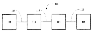
図1Aについて説明する。全体を参照符号100で示す本発明システムの一実施態様は、図示のように、サンプル供給または導入サブシステム102を備える。また、本システム100は、第1導管106によってサンプル供給または導入サブシステム102に接続した蛍光検出サブシステム104を備える。さらに本システム100は、第1信号導管110によって蛍光サブシステム104に接続した分析素子サブシステム108を備える。
1A will be described. One embodiment of the system of the present invention, indicated generally by the
システム100の別な実施態様を図1Bに示す。本システム100は、さらにサンプル供給または導入サブシステム102間に配設された酸化処理サブシステム112を備える。酸化処理サブシステム112は、第2導管114によってサンプル供給または導入サブシステム102に、そして第3導管116によって蛍光検出サブシステム104に接続する。
Another embodiment of the
システム100のさらに別な実施態様を図1Cに示す。本システム100場合、さらに酸化処理サブシステム112と蛍光検出サブシステム104との間に化学発光検出サブシステム118を配設している。化学発光検出サブシステム118は、第4導管120によって酸化処理サブシステム112に、そして第5導管122によって蛍光サブシステム104に接続する。化学発光検出サブシステム118も第2信号導管124によって分析素子サブシステム108に接続する。場合にもよるが、サブシステム118は、酸化されたサンプルまたはサンプル成分にオゾンを導入してNOを少なくするか排除し、これを非干渉酸化窒素であるNO2に転換するオゾン発生素子を単に備えたものでもよい。この構成ではまた、サブシステム118は、オゾンが酸化されたサンプルまたはサンプル成分と混合するチャンバーを備えていてもよい。
Yet another embodiment of the
各サブシステムについて以下詳細に説明する。 Each subsystem will be described in detail below.
本発明に使用するサンプル供給または導入システム102としては、自動サンプラー素子、直接注入用セプタム、連続サンプリング用サンプリングループ、インライン式注入システム、GC、LC、MPLC、HPLC、LPLCなどの分析分離システム、電気泳動を備えた任意のサンプル供給システムを使用できる。あるいは、本発明の分析装置にサンプルを供給または導入するために現在使用されているか、将来使用されるだろうその他の任意のサンプル供給または導入システムも使用可能である。図1Aのシステムの場合、酸化処理などの前処理を行わずに、サンプルを蛍光検出素子に直接導入する。このようなシステムは、一般的には、SO2を含有していることがわかっているか予想されるサンプルを試験するために好適であるが、図1Bおよび図1Cのシステムの場合は、サンプルを酸化処理してSO2を発生し、次に分析するシステムである。もちろん、図1Bおよび図1CのシステムはSO2を含有することがわかっているか予想されるサンプルだけでなく、酸化されていない硫黄や化学結合硫黄を含有するサンプルにも使用できる。
The sample supply or
上記システム実施態様すべてにおいて、分析サブシステムは一般的にはデジタル処理システムであり、このシステムはデジタル処理ユニット、メモリー(キャッシュ、RAM、ROMなど)、大容量記憶装置、周辺素子などを備える。分析素子はPMTなどの検出サブシステムに対応する検出素子からの出力を入力とし、元のサンプル中の分析対象である元素の濃度に信号を転換する。データは表示またはプリントアウトなどされる。
蛍光検出サブシステム
In all of the above system embodiments, the analysis subsystem is typically a digital processing system that includes a digital processing unit, memory (cache, RAM, ROM, etc.), mass storage, peripheral devices, and the like. The analysis element receives the output from the detection element corresponding to the detection subsystem such as PMT, and converts the signal to the concentration of the element to be analyzed in the original sample. Data is displayed or printed out.
Fluorescence detection subsystem
次に図2Aについて説明する。全体を参照符号200で示す本発明の紫外線蛍光検出サブシステムの一実施態様は、図示のように、光源装置202、蛍光反応装置240、および検出素子280を備える。
Next, FIG. 2A will be described. One embodiment of the ultraviolet fluorescence detection subsystem of the present invention, indicated generally by the
光源装置202はエキシマー光源204および電源206を備え、そして場合によっては励起光フィルター208を備える。電源206は、電線用導管210aおよび210bによってエキシマー光源204に接続する。フィルター208が存在する場合には、励起光ビーム212がこれに入射し、励起光ビーム212をフィルター処理し、狭い波長(または周波数)帯の光、即ち目的の波長周囲に厳密に分布する波長帯の光をもつフィルター処理励起光ビーム214を出力する。実施態様にもよるが、目的の波長は、SO2吸収に最適な波長である約220nmである。
The
蛍光反応装置240は、蛍光反応チャンバー242を備える。このチャンバー242のサンプル入口244は、サンプル入口導管246に接続し、そしてサンプル出口248は出口導管250に接続する。また、チャンバー242の励起光口252は励起光ビーム212またはフィルター処理励起光ビーム214と光学的に連絡し、そして検出素子口254は検出素子280と光学的に連絡する。検出素子口254は励起口252に対して直角に設定するが、検出素子口254に入射する励起光の量を少なくするのに十分な角度である限り、任意に設定できる。USP6,075,609およびUSP6,636,314に記載されているように、チャンバー内壁256をミラー化すると、検出素子口254および検出素子280に入射する蛍光光量を増すことができる。なお、これら公報については本開示に援用するものである。
The
検出素子280は信号導管282によって、前述した分析素子サブシステム108に接続する。
The
次に図2Bについて説明する。全体を参照符号200で示す本発明の紫外線蛍光検出サブシステムの一実施態様は、図示のように、光源装置202、蛍光反応装置240および検出素子280を備える。
Next, FIG. 2B will be described. One embodiment of the ultraviolet fluorescence detection subsystem of the present invention, indicated generally by the
光源202はエキシマー光源204および電源206を備え、そして場合に応じて励起光フィルター208を備える。電源206は、電線用導管210aおよび210bによってエキシマー光源204に接続する。フィルター208が存在する場合には、励起光ビーム212がこれに入射し、励起光ビーム212をフィルター処理し、狭い波長(または周波数)帯の光、即ち目的の波長周囲に厳密に分布する波長域の光をもつフィルター処理励起光ビーム214を出力する。実施態様にもよるが、目的の波長は、SO2吸収に最適な波長である約220nmである。
The
蛍光反応装置240は、蛍光反応チャンバー242を備える。このチャンバー242のサンプル入口244は、サンプル入口導管246に接続し、そしてサンプル出口248は出口導管250に接続する。また、チャンバー242の励起光口252は励起光ビーム212またはフィルター処理励起光ビーム214と光学的に連絡し、そして検出素子口254は検出素子280と光学的に連絡する。検出素子口254は励起口252に対して直角に設定するが、検出素子口254に入射する励起光の量を少なくするのに十分な角度である限り、任意に設定できる。USP6,075,609およびUSP6,636,314に記載されているように、チャンバー内壁256をミラー化すると、検出素子口254および検出素子280に入射する蛍光光量を増すことができる。なお、これら公報については本開示に援用するものである。また、蛍光反応チャンバー242は場合に応じて設けられる光強度検出素子/センサー素子258を備え、これを信号導管260によって分析素子108に接続すると、上記のソフトウェアフィードバック制御に利用できる。
The
検出素子280は信号導管282によって、前述した分析素子サブシステム108に接続する。
The
次に図2Cについて説明する。全体を参照符号200で示す本発明の紫外線検出サブシステムの別実施態様は、図示のように、光源装置202、蛍光反応装置240および検出素子280を備える。
Next, FIG. 2C will be described. Another embodiment of the UV detection subsystem of the present invention, indicated generally by the
光源202はエキシマー光源204、電源206および励起光フィルター208を備える。電源206は、電線用導管210aおよび210bによってエキシマー光源204に接続する。フィルター208は、励起光ビーム212がこれに入射し、励起光ビーム212をフィルター処理し、狭い波長(または周波数)帯の光、即ち目的の波長周囲に狭い範囲で分布する波長帯の光をもつフィルター処理励起光ビーム214を出力する。実施態様にもよるが、目的の波長は、SO2吸収に最適な波長である約220nmである。フィルター処理励起光ビーム214は、スプレッダー素子またはコリメーター素子216を通過して拡散ビーム218を形成する。
The
蛍光反応装置240は蛍光反応チャンバー242を備える。このチャンバー242のサンプル入口244は、サンプル入口導管246に接続し、そしてサンプル出口248は出口導管250に接続する。また、チャンバー242の励起光口252は拡散ビーム218と光学的に連絡し、そして検出素子口254は検出素子280と光学的に連絡する。検出素子口254は励起口252に対して直角に設定するが、検出素子口254に入射する励起光の量を少なくするのに十分な角度である限り、任意に設定できる。USP6,075,609およびUSP6,636,314に記載されているように、チャンバー内壁256をミラー化すると、検出素子口254および検出素子280に入射する蛍光光量を増すことができる。なお、これら公報については本開示に援用するものである。また、チャンバー242には場合に応じて光強度検出素子/センサー素子258を設ける。この素子258は信号導管260によって分析素子108に接続し、上記ソフトウェアフィードバック制御に使用できるようにする。また、蛍光反応チャンバー242には蛍光フィルター262を配設できる。
The
検出素子280は信号導管282によって、前述の分析素子サブシステム108に接続する。
The
窒素および硫黄の両者を検出するシステムの場合、酸化処理されたサンプルを2つの部分に分割できる。即ち、硫黄検出システムに行く部分と窒素検出システムに行く部分である。蛍光サブシステムと化学発光サブシステムをもつシステムの場合、化学発光サブシステムはNOとして窒素を測定し、SO2として硫黄を測定する。
高電圧電源
For systems that detect both nitrogen and sulfur, the oxidized sample can be divided into two parts. That is, the part going to the sulfur detection system and the part going to the nitrogen detection system. For systems with a fluorescent subsystem and chemiluminescent subsystem, chemiluminescent subsystem nitrogen was measured as NO, it is measured sulfur as SO 2.
High voltage power supply
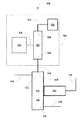
次に図3について説明する。全体を参照符号300で示す本発明のフィードバック/閉回路制御サブシステムの一実施態様は、DC電源302を備える。このDC電源302はエキシマー光源204などの光源の主電源として使用する。DC電源302からブリッジ制御素子304およびMOSFETスイッチユニット306に給電する。ブリッジ制御素子304は13個の入力/出力チャネルa〜mを備える。スイッチユニット306はスイッチ308a&bおよび310a&bを備える。また、スイッチユニット306は7個の入力/出力チャネルt〜zを備える。DC電源302は給電線312+によって入力チャネルaのブリッジ制御素子304に、そして給電線312−によって入力チャネルtのMOSFETスイッチユニット306に制御状態の良好な初期電圧を供給する。制御素子304およびMOSFETスイッチユニット306への入力電圧については、約8V〜約30Vに厳格に調整する。ブリッジ制御素子304は、MOSFETスイッチユニット306のゲート316a〜dを駆動するために使用されるゲート駆動出力314a〜dを備える。これらゲート314a〜dおよび316a〜dが、光源電流および電圧を測定し、過電流保護および過電圧保護を担保するとともに光源輝度を厳格に制御する。
Next, FIG. 3 will be described. One embodiment of the feedback / closed circuit control subsystem of the present invention, indicated generally by the
ブリッジ制御素子チャネルa〜mの定義は次の通りである。
表I
ブリッジ制御素子チャネル
Table I
Bridge control element channel
スイッチユニットチャネルt〜zの定義は次の通りである。
表II
スイッチユニットチャネル
Table II
Switch unit channel
ゲート駆動出力314a〜dは、MOSFETスイッチユニット306のゲート316a〜dに直接接続する。一方のハーフブリッジ320aにおけるスイッチ308aをオンすると同時に、他方のハーフブリッジ320bにおけるスイッチ310aをオンすると、ゲート314a〜dおよびゲート316a〜dにより電流が変圧器318にのみ流れる。一方のハーフブリッジ320a、320bにおけるスイッチ308a、308bのオン時間が他方のハーフブリッジ320b、320aにおけるスイッチ310a、310bのオン時間と正確に重なった場合に、出力を最大化できる。 The gate drive outputs 314a-d are directly connected to the gates 316a-d of the MOSFET switch unit 306. When the switch 308a in one half bridge 320a is turned on and at the same time the switch 310a in the other half bridge 320b is turned on, current flows only to the transformer 318 through the gates 314a to 316d and gates 316a to 316d. The output can be maximized when the on time of the switches 308a, 308b in one half bridge 320a, 320b exactly overlaps the on time of the switches 310a, 310b in the other half bridge 320b, 320a.
光源204の輝度を設定する場合、本発明の装置および方法は、2つの基本的調光方法を利用する。第1調光方法はアナログ調光である。この場合、DC電圧が電流調整素子によって調整される光源204電流をプログラム処理するため、光源204電流を直接制御できる。第2調光方法はバースト調光である。この場合、負荷サイクルを一定にした状態で、低周波において光源204をオンオフする。バースト調光方法は内部方式(即ち、DC電圧が、発生されたバーストパルスの負荷サイクルをプログラム処理する)か、あるいは外部方式(即ち、外部PWM信号を直接使用してバースト調光を行う)のいずれか方式であればよい。調光回路は、ブリッジ制御素子304に集積一体化する。これら調光方法は独立して適用できる。
In setting the brightness of the
また、高電圧電源300は、ブリッジ制御素子304の周波数プログラム処理入力チャネルfとして働く内部動作周波数を制御する周波数設定抵抗素子322を備える。過電流保護入力を使用して、電流センサー素子324から誘導される電圧をモニタリングする。光源電流は、シャント抵抗素子326の電圧から誘導される。電流測定装置328が、光源電流調整に使用される電流を測定する。光源電圧は、第1キャパシター素子332および第2キャパシター素子334を備えたキャパシタンス分割素子330から誘導される。また、電圧測定装置336が、ランプ電圧調整および光源過電圧保護に使用される電圧を測定する。高電圧電源300は、高電圧出力338および340を出力する。
酸化処理サブシステム
The high
Oxidation subsystem
図4Aについて説明する。本発明の酸化処理サブシステムまたは燃焼処理サブシステムの一実施態様は、全体を参照符号400で示す。図示のように、このサブシステムは燃焼炉402および酸化剤供給部404を備える。
FIG. 4A will be described. One embodiment of the oxidation or combustion treatment subsystem of the present invention is indicated generally by the
燃焼炉402は、サンプル入力導管408に接続されたサンプル入口406および酸化処理されたサンプルの導管412に接続された酸化処理サンプル出口410を備える。また、燃焼炉402は酸化処理域414およびヒーター素子416を備える。さらに、燃焼炉402の酸化剤入口418は、酸化剤導管420に接続する。
図4Bについて説明する。全体を参照符号440で示す本発明の酸化処理サブシステムの一実施態様は、図示のように、燃焼炉442および酸化剤供給部444を備える。
FIG. 4B will be described. One embodiment of the oxidation processing subsystem of the present invention, generally designated by
燃焼炉442は、サンプル入力導管450に接続されたサンプル入口448および酸化剤導管454に接続された酸化剤入口452を有する噴霧器446を備える。また、燃焼炉442は酸化処理域546およびヒーター素子458を備える。また、燃焼炉442の酸化処理サンプル出口460は、酸化処理サンプル導管462に接続する。
図4Cについて説明する。全体を参照符号470で示す本発明の酸化処理サブシステムの一実施態様は、図示のように、燃焼炉472および酸化剤供給部474を備える。
FIG. 4C will be described. One embodiment of the oxidation processing subsystem of the present invention, generally designated by
燃焼炉472は、サンプル入力導管480に接続されたサンプル入口478および酸化剤導管484に接続された酸化剤入口482を有する噴霧器476を備える。また、燃焼炉472は酸化処理域486およびヒーター素子488を備え、その第2酸化剤入口490を第2酸化剤導管492に接続する。燃焼炉472の酸化処理サンプル出口494は、酸化処理サンプル導管496に接続する。酸化処理域486は、2つの静止ミキサー498を備える。これら2つの静止ミキサー498および第2酸化剤入口490を設けたため、燃焼効率が改善する。
化学発光検出サブシステム
次に図5について説明する。全体を参照符号500で示す本発明の化学発光サブシステムの一実施態様は、図示のように、オゾン反応チャンバー502、オゾン源504および検出素子506を備える。
Chemiluminescence Detection Subsystem Now referring to FIG. One embodiment of the chemiluminescence subsystem of the present invention, indicated generally by the
オゾン反応チャンバー502は、オゾン導管510に接続されたオゾン入口508を備え、またサンプル導管514に接続されたサンプル入口512を備える。このオゾン反応チャンバー502は、サンプル出口導管518に接続されたサンプル出口516を備え、検出素子口520を備える。このチャンバーの内壁をミラー化すると、検出素子口520および検出素子504に入射する化学発光光の量を大きくできる。この点については、USP6075609およびUSP6636314に詳しい説明がある。なお、これら公報の開示内容は本開示に援用されている。
The
オゾン源504は、オゾン発生器522およびオゾン発生器電源524を備える。この電源524は、電線用導管526によってオゾン発生器522に接続する。オゾン発生器522のオゾン出口528は、オゾン導管510に接続し、オゾン発生器522の酸素または空気入口530は、酸素用または空気用電線用導管534によって酸素または空気供給部532に接続する。オゾン源504から十分な量のオゾンをオゾン反応チャンバーに供給し、NOを化学発光活性種に酸化するため、化学発光サブシステム内において窒素がSO2検出に干渉することが少なくなる。
The
検出素子504については、データ導管536によって上記分析素子サブシステムに接続する。
The
あるいは、オゾンを酸化処理サンプルまたはサンプル成分に添加するだけでもNOを除去でき、従ってSO2検出にNOが干渉することがなくなる。この点については、USP7244395に詳しい説明がある。なお、この公報の開示内容は本開示に援用されている。
エキシマー光源
Alternatively, NO can be removed simply by adding ozone to the oxidized sample or sample components, so that NO does not interfere with SO 2 detection. This point is described in detail in USP 7244395. The disclosure of this publication is incorporated in this disclosure.
Excimer light source
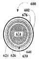
図6Aおよび図6Bについて説明する。全体を参照符号600で示す本発明のエキシマー光源サブシステムの一実施態様は、図示のように、ハウジング602、エキシマー光源装置620および光源電源装置670を備える。なお、エキシマー光源装置620はハウジング602によって取り囲まれている。
6A and 6B will be described. One embodiment of the excimer light source subsystem of the present invention, indicated generally by the
エキシマー光源装置620は、誘電体バリアガスエンクロージャー622を備える。このエンクロージャー622は、外側誘電体バリア624、内側誘電体バリア626および端部誘電体バリア628を備え、これらがエンクロージャー内部630を構成する。エキシマー光源装置620の出力光ウインドー632は、エンクロージャー622の遠位端部634およびハウジング602の遠位端部604に設け、そして近位端部636は、ハウジング606の近位端部付近に設ける。さらに、エキシマー光源装置620は、以下に説明するように内部電極を配設できる中空の内部領域638を備える。エンクロージャー内部630には、目的の周波数を中心とした狭い周波数域の光を発光するエキシマーガス640を充填する。すべてのエキシマーが、他の周波数を中心とした光を発光できることはいうまでもない。なお、この他の光は蛍光チャンバーにおいて不要な背景になることが多く、あるいは蛍光チャンバーに存在するSO2以外の他の種を励起することも多い。このような事態を想定して、光源装置620には下記の実施態様で説明するように、フィルターを設けることができる。
The excimer
電源装置670は電源672、導電性材料のメッシュからなる内側電極674、および固体の導電性材料からなり(即ち、シェル状か中空状管の形を取った)かつ内面678をミラー化した外側電極676を備える。内側電極674は、第1導電性導管680によって電源672に接続し、そして外側電極676は、第2導電性導管682によって電源672に接続する。第1導電性導管680および第2導電性導管682は、電源672の出力に接続する。電源672は、ガスエンクロージャー622の内部630においてエキシマーガス種640を発生できる出力を出す。一般的にいって、この出力は安定な光出力を出すように最適化された高周波波形出力の形を取る。波形は、発振器波形であり、純粋な正弦波形か、正弦波形(例えば正方波形など)の合成波形、あるいは安定なエキシマー光源出力を出力できるその他の連続発振波形であればよい。
The
次に図6Cおよび図6Dについて説明する。全体を参照符号600で示す本発明のエキシマー光源サブシステムの別な実施態様は、図示のように、ハウジング602、エキシマー光源装置620、および光源電源装置670を備える。なお、エキシマー光源装置620はハウジングによって取り囲まれている。
Next, FIGS. 6C and 6D will be described. Another embodiment of the excimer light source subsystem of the present invention, indicated generally by the
エキシマー光源装置620は誘電体バリアガスエンクロージャー622を備える。このエンクロージャー622は、外側誘電体バリア624、内側誘電体バリア626および端部誘電体バリア628を備え、これらがエンクロージャー内部630を構成する。エキシマー光源装置620の出力光ウインドー632は、エンクロージャー622の遠位端部634およびハウジング602の遠位端部604に設け、そして近位端部636は、ハウジング606の近位端部付近に設ける。さらに、エキシマー光源装置620は、以下に説明するように内部電極を配設できる中空の内部領域638を備える。エキシマー光源装置620は、目的の周波数を中心としない光を減らす光フィルター642も備える。エンクロージャー内部630には、目的の周波数を中心とした狭い周波数域の光を発光するエキシマーガス640を充填する。すべてのエキシマーが、他の周波数を中心とした光を発光できることはいうまでもない。なお、この他の光は蛍光チャンバーにおいて不要な背景になることが多く、あるいは蛍光チャンバーに存在するSO2以外の他の種を励起することも多い。このような事態を想定して、光源装置620には下記の実施態様で説明するように、フィルターを設けることができる。
The excimer
電源装置670は電源672、固体の導電性材料からなる(即ち、シェル状か中空状管の形を取った)内側電極674、および固体の導電性材料からなり(即ち、シェル状か中空状管の形を取った)かつ内面678をミラー化した外側電極676を備える。内側電極674は、第1導電性導管680によって電源672に接続し、そして外側電極676は、第2導電性導管682によって電源672に接続する。第1導電性導管680および第2導電性導管682は、電源672の対向ポールに接続する。電源672は、ガスエンクロージャー622の内部630においてエキシマーガス種640を発生できる出力を出す。一般的にいって、この出力は安定な光出力を出すように最適化された高周波波形出力の形を取る。波形は、発振器波形であり、純粋な正弦波形か、正弦波形(例えば正方波形など)の合成波形、あるいは安定なエキシマー光源出力を出力できるその他の連続発振波形であればよい。
The
次に図6Eおよび図6Fについて説明する。全体を参照符号600で示す本発明のエキシマー光源サブシステムのさらに別な実施態様は、図示のように、ハウジング602、エキシマー光源装置620、および光源電源装置670を備える。なお、エキシマー光源装置620はハウジングによって取り囲まれている。
Next, FIGS. 6E and 6F will be described. Yet another embodiment of the excimer light source subsystem of the present invention, indicated generally by the
エキシマー光源装置620は誘電体バリアガスエンクロージャー622を備える。このエンクロージャー622は、外側誘電体バリア624、内側誘電体バリア626および端部誘電体バリア628を備え、これらがエンクロージャー内部630を構成する。エキシマー光源装置620の出力光ウィンドー632は、エンクロージャー622の遠位端部634およびハウジング602の遠位端部604に設け、そして近位端部636は、ハウジング606の近位端部付近に設ける。さらに、エキシマー光源装置620は、以下に説明するように内部電極を配設できる中空の内部領域638を備える。エキシマー光源装置620は、目的の周波数を中心としない光を減らす光フィルター642も備える。エンクロージャー内部630には、目的の周波数を中心とした狭い周波数域の光を発光するエキシマーガス640を充填する。すべてのエキシマーが、他の周波数を中心とした光を発光できることはいうまでもない。なお、この他の光は蛍光チャンバーにおいて不要な背景になることが多く、あるいは蛍光チャンバーに存在するSO2以外の他の種を励起することも多い。このような事態を想定して、光源装置620には下記の実施態様で説明するように、フィルターを設けることができる。
The excimer
電源装置670は電源672、固体ロッド状導電性材料からなる内側電極674、および固体の導電性材料からなり(即ち、シェル状か中空状管の形を取った)かつ内面678をミラー化した外側電極676を備える。内側電極674は図6Eに示すように、ミラー化かつテーパー化してもよく、あるいは図6Fに示すようにテーパー化処理しなくてもよい。テーパー化電極674のテーパー化方向は、端部604に向かう方向に設定する。このテーパーがあるため、外側電極676のテーパーと調和して動作するウインドー632を励起する光が増加する。内側電極674は、第1導電性導管680によって電源672に接続し、そして外側電極676は、第2導電性導管682によって電源672に接続する。第1導電性導管680および第2導電性導管682は、電源672の対向ポールに接続する。電源672は、ガスエンクロージャー622の内部630においてエキシマーガス種640を発生できる出力を出す。一般的にいって、この出力は安定な光出力を出すように最適化された高周波波形出力の形を取る。波形は、発振器波形であり、純粋な正弦波形か、正弦波形(例えば正方波形など)の合成波形、あるいは安定なエキシマー光源出力を出力できるその他の連続発振波形であればよい。
The
異なる3種類の内側電極674について説明してきたが、内側電極の厳密な特性からみて、これら一般的な3種類の電極を合成して使用してもよく、あるいは内面誘電体バリア626に隣接する内部領域638に配設できる他の電極を使用してもよい。また、外側電極676については、外側電極の内面間で紫外線光を反射できるように内面がミラー化されている限りは、直線部分およびテーパー化部分を設けてもよい。
エキシマー光源出力
Three different types of
Excimer light source output
図7Aおよび図7Bに本発明のエキシマー光源サブシステムの実施態様の光出力スペクトルを示す。即ち、図7Aに示す出力スペクトルは、200nm〜900nmにある光源であり、図7Bに示す出力スペクトルは、200nm〜250nmの波長の光に焦点を当てた展開モードにある。両スペクトルから、ランプ即ち光源が222nmを中心とした大きな信号を出力していることが明らかである。励起光フィルターは、約225nmを超える波長すべてを抑制または遮断するものである。他の実施態様では、これらフィルターは約224nmを超える波長の光を遮断するものである。222nmを中心とし、そして約205nm〜約225nmの波長帯をもつ、あるいは別な実施態様では205nm〜224nmの波長帯をもつ狭い波長の光を出力するのは、サンプルに存在する恐れのあるNOの同時励起を抑制または排除するためである。SO2およびNOの吸収スペクトルおよび発光スペクトルは、約190nm〜約230nmの範囲にある紫外線域と同じ電磁スペクトル帯で発生する。ところが、NO吸収スペクトルは、多数の比較的広い間隔の吸収ピークからなり、その一方で、SO2吸収スペクトルは、多数のより狭い間隔の吸収ピークからなる。約222nmを中心とした狭い波長帯にある光は、NOの2つの吸収ピーク間にあり、その一方でSO2吸収ピークと重なっている。従って、SO2吸収を励起するのに好適な光は、フィルター処理エキシマー光源からの光や、より理想的には将来利用可能になると考えられるレーザーからの光などの222nmを中心とした狭い波長帯の光であり、この光はNO励起を抑制または最小限に抑えることができ、従ってSO2検出におけるNO干渉を抑制できる。USP7,244,395に開示されているように、蛍光反応チャンバーにおいて紫外線光を照射する前にサンプルにオゾンを添加すると、NOの破壊によりNO干渉を抑制または排除できる。この公報の開示内容は、本明細書に援用するものである。このように、本発明の一実施態様の場合、NO化学発光装置は、222nmを中心とする紫外線光に対して不活性な酸化窒素NO2にNOを転換するオゾン導入ユニットだけで構成できる。 7A and 7B show the light output spectrum of an embodiment of the excimer light source subsystem of the present invention. That is, the output spectrum shown in FIG. 7A is a light source in the range of 200 nm to 900 nm, and the output spectrum shown in FIG. 7B is in a deployment mode focused on light having a wavelength of 200 nm to 250 nm. From both spectra it is clear that the lamp or light source outputs a large signal centered at 222 nm. The excitation light filter suppresses or blocks all wavelengths above about 225 nm. In other embodiments, the filters block light having a wavelength greater than about 224 nm. Narrow wavelength light centered around 222 nm and having a wavelength band of about 205 nm to about 225 nm, or in another embodiment having a wavelength band of 205 nm to 224 nm, is the presence of NO that may be present in the sample. This is to suppress or eliminate simultaneous excitation. Absorption and emission spectra of SO 2 and NO are generated in the same electromagnetic spectral band ultraviolet region in the range of about 190nm~ about 230 nm. However, the NO absorption spectrum consists of a number of relatively widely spaced absorption peaks, while the SO 2 absorption spectrum consists of a number of narrower spaced absorption peaks. Light in a narrow wavelength band centered at about 222 nm is between the two absorption peaks of NO, while overlapping the SO 2 absorption peak. Therefore, suitable light to excite SO 2 absorption is a narrow wavelength band centered around 222 nm, such as light from a filtered excimer light source, or more ideally from a laser that will be available in the future. This light can suppress or minimize NO excitation and therefore NO interference in SO 2 detection. As disclosed in US Pat. No. 7,244,395, when ozone is added to a sample before irradiation with ultraviolet light in a fluorescence reaction chamber, NO interference can be suppressed or eliminated by destruction of NO. The disclosure of this publication is incorporated herein by reference. Thus, in the case of one embodiment of the present invention, the NO chemiluminescent device can be composed of only an ozone introduction unit that converts NO into NO 2 inactive to ultraviolet light centered at 222 nm.
本明細書で引用した従来例は、そのうちの幾つかが単に例示に過ぎない場合でも、法律で許された援用例である。本発明を好適な実施態様について説明してきたが、当業者ならば、本開示から、本発明の以上説明し、かつ特許請求の範囲に記載した精神および範囲から逸脱しなくても、各種の変更が本発明において可能であることを理解できるはずである。 The prior art cited in this specification is a legally permitted usage example, even if some of them are merely illustrative. While the invention has been described in terms of preferred embodiments, those skilled in the art will recognize that various modifications can be made from the present disclosure without departing from the spirit and scope of the invention as described above and set forth in the claims. It should be understood that is possible in the present invention.
窒素および硫黄の両者を検出するシステムの場合、酸化処理されたサンプルを2つの部分に分割できる。即ち、硫黄検出システムに行く部分と窒素検出システムに行く部分である。蛍光サブシステムと化学発光サブシステムをもつシステムの場合、化学発光サブシステムはNOとして窒素を測定し、蛍光サブシステムはSO2として硫黄を測定する。 For systems that detect both nitrogen and sulfur, the oxidized sample can be divided into two parts. That is, the part going to the sulfur detection system and the part going to the nitrogen detection system. For a system with a fluorescence subsystem and a chemiluminescence subsystem, the chemiluminescence subsystem measures nitrogen as NO and the fluorescence subsystem measures sulfur as SO 2 .
Claims (12)
サンプルを供給するサンプル供給システムを有し;
エキシマー光源および高電圧電源を備え、このエキシマー光源が検出すべき蛍光活性種の最適な吸収周波数を中心とした狭い波長帯または周波数帯をもつ励起光を発光する光源装置を有し、
サンプルを受け取るサンプル入口と、
検出チャンバーからサンプルを排出するサンプル出口と、
エキシマー光源と光学的に連絡し、かつ検出チャンバーへの励起光を受け取る励起光入口と、そして
励起光によって励起された検出チャンバー内の蛍光活性種が発光する蛍光の一部を受け取る蛍光出口を備えた検出チャンバーを有し、かつ
上記光出口と光学的に連絡し、かつこの光出口を通る蛍光の強度を検出し、この蛍光強度を比例的な電流信号に転換する検出素子を有する検出システムを有し;そして
上記検出素子と電気的に連絡し、この検出素子からの電流信号を検出チャンバー中の蛍光活性種の濃度およびサンプル中の対応する元素の濃度に転換する分析素子を有することを特徴とする分析装置。
In a sample or sample component analyzer,
A sample supply system for supplying samples;
An excimer light source and a high-voltage power source, and a light source device that emits excitation light having a narrow wavelength band or frequency band centered on the optimum absorption frequency of the fluorescent active species to be detected by the excimer light source;
A sample inlet to receive the sample,
A sample outlet for discharging the sample from the detection chamber;
An excitation light inlet that is in optical communication with the excimer light source and receives excitation light into the detection chamber, and a fluorescence outlet that receives a portion of the fluorescence emitted by the fluorescent active species in the detection chamber excited by the excitation light A detection system having a detection chamber that is in optical communication with the light exit, detects the intensity of fluorescence passing through the light exit, and converts the fluorescence intensity into a proportional current signal. And having an analytical element that is in electrical communication with the sensing element and converts a current signal from the sensing element into a concentration of fluorescent active species in the detection chamber and a corresponding element in the sample. Analyzing device.
燃焼域、
酸化剤供給サブシステム、
サンプル入口、
少なくとも一つの酸化剤入口、
検出チャンバーのサンプル入口に接続された出口、および
燃焼域を高温に維持するヒーター素子を備え、そして
この燃焼システムで、サンプル中のほぼすべての酸化性成分を対応する酸化物に酸化する請求項1に記載の分析装置。
A combustion system is further disposed between the sample supply system and the detection system, the combustion system comprising:
Combustion zone,
Oxidant supply subsystem,
Sample inlet,
At least one oxidant inlet,
An outlet connected to the sample inlet of the detection chamber, and a heater element that maintains the combustion zone at a high temperature, wherein the combustion system oxidizes substantially all oxidizable components in the sample to the corresponding oxide. The analyzer described in 1.
The analyzer of claim 1, wherein the sample is a hydrocarbon-containing sample, fuel, chemical reactor stream, purifier stream, or vent gas stream.
The analyzer according to claim 3, wherein the fuel is selected from the group consisting of gasoline, kerosene, jet fuel, diesel fuel, other hydrocarbon fuels, and mixtures or composites thereof.
The analyzer according to claim 1, wherein the element is selected from the group consisting of nitrogen, sulfur, and a mixture or complex thereof.
6. The analyzer according to claim 5, wherein the fluorescent active species is sulfur dioxide, the excimer light source is a krypton chloride gas excimer light source, and the center of the wavelength band is about 222 nm.
The analyzer according to claim 1, wherein the sample supply system is selected from the group consisting of an autosampler, a direct injection septum, a sampling loop for continuous sampling, an analytical separation system, and a mixture or complex thereof.
The analytical apparatus according to claim 9, wherein the analytical separation system is selected from the group consisting of GC, LC, MPLC, HPLC, LPLC, electrophoresis apparatus and a mixture or complex thereof.
Furthermore, the optical sensor element that continuously monitors the output light characteristic value of the light source, and the current light source output characteristic value are received, and the current value is compared with a predetermined set of light source output special values derived during the verification process. The analyzer according to claim 1, further comprising a software detection element signal feedback correction device including a processing unit that outputs a change value and adjusts the detection element signal based on the change value.
入力DC電圧を出力するDC電源、
ブリッジ制御素子、
スイッチユニット、
変圧器、
周波数設定抵抗素子、
電流センサー素子、
分圧素子、
電圧測定装置、
シャント抵抗素子、および
電流測定装置を有し、
エキシマー光源に供給されている電圧および電流をブリッジ制御素子によって制御し、検定間にある所望レベルに励起光強度を維持する請求項1に記載の分析装置。
The high voltage power supply
DC power supply that outputs input DC voltage,
Bridge control element,
Switch unit,
Transformer,
Frequency setting resistor element,
Current sensor element,
Voltage divider,
Voltage measuring device,
A shunt resistor element and a current measuring device,
The analyzer according to claim 1, wherein the voltage and current supplied to the excimer light source are controlled by a bridge control element to maintain the excitation light intensity at a desired level between calibrations.
酸化剤供給ユニットと;
燃焼域、およびサンプルの酸化性成分を対応する酸化物および水に酸化するのに十分な温度に燃焼域を維持するヒーター素子を備えた炉;
検出チャンバーと、
上記炉と検出チャンバーとを相互接続する伝達管と、
検出チャンバーと光学的に連絡し、検出すべき蛍光活性種の最適吸収周波数を中心とした狭い波長帯または周波数帯の光を発光するエキシマー光源と、
検出チャンバーと光学的に連絡して、励起光によって励起された検出チャンバー内の蛍光活性種によって発光した蛍光の一部を検出する光検出素子と、そして
光検出素子の出力を少なくともの一つの酸化物の元素のサンプルにおける濃度に転換する分析素子を備えた検出システムを有する装置にサンプルを供給する工程、
サンプルの酸化性化合物を対応する酸化物および水に酸化して酸化処理混合物を形成する工程、
酸化処理混合物を検出チャンバーに送る工程、
励起光で酸化処理混合物の酸化物を励起して蛍光活性種を形成する工程、
励起光に励起された検出チャンバー内の蛍光活性種が発光する蛍光部分を検出する工程、および
励起光によって励起された検出チャンバー内の蛍光活性種が発光する蛍光部分からサンプル内の所定元素の濃度を決定する工程からなることを特徴とする方法。
A sample supply unit;
An oxidant supply unit;
A furnace with a heater element that maintains the combustion zone and the combustion zone at a temperature sufficient to oxidize the oxidizing components of the sample to the corresponding oxide and water;
A detection chamber;
A transmission tube interconnecting the furnace and the detection chamber;
An excimer light source that optically communicates with the detection chamber and emits light in a narrow wavelength band or frequency band centered on the optimum absorption frequency of the fluorescent active species to be detected;
A light detecting element in optical communication with the detection chamber to detect a portion of the fluorescence emitted by the fluorescent active species in the detection chamber excited by the excitation light, and at least one oxidation of the output of the light detecting element Supplying the sample to a device having a detection system with an analytical element that converts to a concentration in the sample of the element of the object,
Oxidizing a sample oxidizing compound to the corresponding oxide and water to form an oxidation treatment mixture;
Sending the oxidation mixture to the detection chamber;
Exciting the oxide of the oxidation mixture with excitation light to form fluorescent active species;
A step of detecting a fluorescent part emitted by the fluorescent active species in the detection chamber excited by the excitation light, and a concentration of a predetermined element in the sample from the fluorescent part emitted by the fluorescent active species in the detection chamber excited by the excitation light. A method comprising the step of determining
Applications Claiming Priority (3)
| Application Number | Priority Date | Filing Date | Title |
|---|---|---|---|
| US12/270,800 US20100118301A1 (en) | 2008-11-13 | 2008-11-13 | System for analyzing a sample or a sample component and method for making and using same |
| US12/270,800 | 2008-11-13 | ||
| PCT/US2009/064391 WO2010056998A1 (en) | 2008-11-13 | 2009-11-13 | A system for analyzing a sample or a sample component and method for making and using same |
Publications (1)
| Publication Number | Publication Date |
|---|---|
| JP2012508890A true JP2012508890A (en) | 2012-04-12 |
Family
ID=42164912
Family Applications (1)
| Application Number | Title | Priority Date | Filing Date |
|---|---|---|---|
| JP2011536516A Pending JP2012508890A (en) | 2008-11-13 | 2009-11-13 | Sample or sample component analysis system and methods for making and using the system |
Country Status (4)
| Country | Link |
|---|---|
| US (2) | US20100118301A1 (en) |
| EP (1) | EP2347246A4 (en) |
| JP (1) | JP2012508890A (en) |
| WO (1) | WO2010056998A1 (en) |
Families Citing this family (24)
| Publication number | Priority date | Publication date | Assignee | Title |
|---|---|---|---|---|
| US10343939B2 (en) | 2006-06-06 | 2019-07-09 | Evoqua Water Technologies Llc | Ultraviolet light activated oxidation process for the reduction of organic carbon in semiconductor process water |
| US12103874B2 (en) | 2006-06-06 | 2024-10-01 | Evoqua Water Technologies Llc | Ultraviolet light activated oxidation process for the reduction of organic carbon in semiconductor process water |
| US8081304B2 (en) | 2006-07-31 | 2011-12-20 | Visualant, Inc. | Method, apparatus, and article to facilitate evaluation of objects using electromagnetic energy |
| US9725343B2 (en) | 2007-04-03 | 2017-08-08 | Evoqua Water Technologies Llc | System and method for measuring and treating a liquid stream |
| WO2013138159A1 (en) * | 2012-03-15 | 2013-09-19 | Amgen Inc. | Methods of determining exposure to uv light |
| US9316581B2 (en) | 2013-02-04 | 2016-04-19 | Visualant, Inc. | Method, apparatus, and article to facilitate evaluation of substances using electromagnetic energy |
| US9041920B2 (en) | 2013-02-21 | 2015-05-26 | Visualant, Inc. | Device for evaluation of fluids using electromagnetic energy |
| US9664610B2 (en) | 2013-03-12 | 2017-05-30 | Visualant, Inc. | Systems for fluid analysis using electromagnetic energy that is reflected a number of times through a fluid contained within a reflective chamber |
| US9804076B2 (en) | 2013-03-13 | 2017-10-31 | Baker Hughes, A Ge Company, Llc | Use of detection techniques for contaminant and corrosion control in industrial processes |
| JP6213191B2 (en) * | 2013-11-28 | 2017-10-18 | 株式会社島津製作所 | Gas analyzer |
| JP6260329B2 (en) * | 2014-02-17 | 2018-01-17 | オムロン株式会社 | CURRENT MEASURING DEVICE, ITS CONTROL METHOD, CONTROL PROGRAM, RECORDING MEDIUM, AND POWER MEASURING DEVICE |
| US9630863B2 (en) * | 2014-03-28 | 2017-04-25 | Neptune-Benson, Llc | Advanced oxidation system and method in a UV reactor with electrode |
| US11161762B2 (en) | 2015-01-21 | 2021-11-02 | Evoqua Water Technologies Llc | Advanced oxidation process for ex-situ groundwater remediation |
| CA2918564C (en) | 2015-01-21 | 2023-09-19 | Evoqua Water Technologies Llc | Advanced oxidation process for ex-situ groundwater remediation |
| NL2017426B1 (en) * | 2016-09-06 | 2018-03-13 | Ac Analytical Controls B V | Method for chemiluminescent sulphur detection and a furnace |
| US10466174B2 (en) * | 2016-12-13 | 2019-11-05 | Infineon Technologies Ag | Gas analyzer including a radiation source comprising a black-body radiator with at least one through-hole and a collimator |
| DE102016125840B4 (en) * | 2016-12-29 | 2018-11-08 | Infineon Technologies Ag | Gas analyzer |
| CN107764285B (en) * | 2017-09-20 | 2021-02-02 | 北京航空航天大学 | Photoelectric detection assembly power supply rejection ratio test system based on phase-locked amplifier |
| US20220011237A1 (en) * | 2018-12-12 | 2022-01-13 | Shimadzu Corporation | Sulfur chemiluminescence detector |
| CN109831867B (en) * | 2019-01-31 | 2024-03-01 | 中国农业科学院农业质量标准与检测技术研究所 | Dielectric barrier discharge device and mercury analysis method thereof |
| CN110823370A (en) * | 2019-11-20 | 2020-02-21 | 西安应用光学研究所 | Ultraviolet weak light detector radiation sensitivity calibration device based on photon counting method |
| RU2741745C1 (en) * | 2020-07-03 | 2021-01-28 | Федеральное государственное бюджетное учреждение науки Институт сильноточной электроники Сибирского отделения Российской академии наук, (ИСЭ СО РАН) | Method for remote detection in air of hazardous substances containing a nitro group |
| EP4089401A1 (en) * | 2021-05-10 | 2022-11-16 | Siemens Aktiengesellschaft | Measuring device and method for measuring at least two different components of a fluid using raman scattering and chemiluminescence |
| CN116608887B (en) * | 2023-07-17 | 2023-10-13 | 山东科技大学 | Disposable ocean current profiler test calibration device and method |
Citations (12)
| Publication number | Priority date | Publication date | Assignee | Title |
|---|---|---|---|---|
| JPS63142742U (en) * | 1987-03-11 | 1988-09-20 | ||
| JPH0763683A (en) * | 1993-08-27 | 1995-03-10 | Shimadzu Corp | Fluorescence analyzer |
| JPH08145889A (en) * | 1994-11-21 | 1996-06-07 | Shimadzu Corp | Fluorescence measuring apparatus |
| JPH10115584A (en) * | 1996-10-11 | 1998-05-06 | Dkk Corp | Fluorescent flow cell |
| JPH11233071A (en) * | 1998-02-13 | 1999-08-27 | Ushio Inc | Dielectric barrier discharge lamp illuminant device |
| JP2000065699A (en) * | 1998-08-19 | 2000-03-03 | Mitsubishi Chemicals Corp | Analytical sample-burning device, method for controlling supply of inert gas, oxygen-containing gas in analytical sample-burning device, and analytical system having sample-burning device |
| US6636314B1 (en) * | 1998-03-26 | 2003-10-21 | Antek Instruments, L.P. | Apparatus and methods for improving fluorescence detectors |
| JP2006266736A (en) * | 2005-03-22 | 2006-10-05 | Horiba Ltd | Exhaust gas analyzer |
| US20070040516A1 (en) * | 2005-08-15 | 2007-02-22 | Liang Chen | AC to DC power supply with PFC for lamp |
| JP2007524801A (en) * | 2002-12-27 | 2007-08-30 | オルストウスキー,フラネック | Excimer UV-excited fluorescence detection |
| JP2008082808A (en) * | 2006-09-27 | 2008-04-10 | Dia Instr:Kk | Analyzer |
| JP2008109815A (en) * | 2006-10-27 | 2008-05-08 | Daihen Corp | High-frequency power supply unit |
Family Cites Families (8)
| Publication number | Priority date | Publication date | Assignee | Title |
|---|---|---|---|---|
| US4045679A (en) * | 1976-05-27 | 1977-08-30 | W. R. Grace & Co. | Fluorescent gas analyzer |
| US4968148A (en) * | 1984-03-01 | 1990-11-06 | Molecular Devices Corporation | Single source multi-site photometric measurement system |
| US4586118A (en) * | 1984-06-05 | 1986-04-29 | The United States Of America As Represented By The United States Department Of Energy | Capacitor charging FET switcher with controller to adjust pulse width |
| ZA862614B (en) * | 1986-04-08 | 1986-12-30 | David John Cockram | Controller for gas discharge lamps |
| US5916523A (en) * | 1996-12-04 | 1999-06-29 | Antek Instruments, Inc. | Methods for near simultaneous chemiluminescent sulfur and nitrogen detection |
| DE19958404C2 (en) * | 1999-12-03 | 2002-04-04 | Xcellsis Gmbh | Device for the selective catalytic oxidation of carbon monoxide |
| WO2006017644A2 (en) * | 2004-08-03 | 2006-02-16 | Franek Olstowski | Improved closed-loop light intensity control and related fluorescence application method |
| JP2006172749A (en) * | 2004-12-13 | 2006-06-29 | Ushio Inc | Lamp lighting circuit |
-
2008
- 2008-11-13 US US12/270,800 patent/US20100118301A1/en not_active Abandoned
-
2009
- 2009-11-13 EP EP09826839A patent/EP2347246A4/en not_active Withdrawn
- 2009-11-13 WO PCT/US2009/064391 patent/WO2010056998A1/en active Application Filing
- 2009-11-13 JP JP2011536516A patent/JP2012508890A/en active Pending
-
2011
- 2011-08-12 US US13/209,179 patent/US20120037817A1/en not_active Abandoned
Patent Citations (12)
| Publication number | Priority date | Publication date | Assignee | Title |
|---|---|---|---|---|
| JPS63142742U (en) * | 1987-03-11 | 1988-09-20 | ||
| JPH0763683A (en) * | 1993-08-27 | 1995-03-10 | Shimadzu Corp | Fluorescence analyzer |
| JPH08145889A (en) * | 1994-11-21 | 1996-06-07 | Shimadzu Corp | Fluorescence measuring apparatus |
| JPH10115584A (en) * | 1996-10-11 | 1998-05-06 | Dkk Corp | Fluorescent flow cell |
| JPH11233071A (en) * | 1998-02-13 | 1999-08-27 | Ushio Inc | Dielectric barrier discharge lamp illuminant device |
| US6636314B1 (en) * | 1998-03-26 | 2003-10-21 | Antek Instruments, L.P. | Apparatus and methods for improving fluorescence detectors |
| JP2000065699A (en) * | 1998-08-19 | 2000-03-03 | Mitsubishi Chemicals Corp | Analytical sample-burning device, method for controlling supply of inert gas, oxygen-containing gas in analytical sample-burning device, and analytical system having sample-burning device |
| JP2007524801A (en) * | 2002-12-27 | 2007-08-30 | オルストウスキー,フラネック | Excimer UV-excited fluorescence detection |
| JP2006266736A (en) * | 2005-03-22 | 2006-10-05 | Horiba Ltd | Exhaust gas analyzer |
| US20070040516A1 (en) * | 2005-08-15 | 2007-02-22 | Liang Chen | AC to DC power supply with PFC for lamp |
| JP2008082808A (en) * | 2006-09-27 | 2008-04-10 | Dia Instr:Kk | Analyzer |
| JP2008109815A (en) * | 2006-10-27 | 2008-05-08 | Daihen Corp | High-frequency power supply unit |
Also Published As
| Publication number | Publication date |
|---|---|
| WO2010056998A1 (en) | 2010-05-20 |
| EP2347246A4 (en) | 2013-01-16 |
| EP2347246A1 (en) | 2011-07-27 |
| US20120037817A1 (en) | 2012-02-16 |
| US20100118301A1 (en) | 2010-05-13 |
Similar Documents
| Publication | Publication Date | Title |
|---|---|---|
| JP2012508890A (en) | Sample or sample component analysis system and methods for making and using the system | |
| US11237141B2 (en) | Gas analyzer for measuring nitrogen oxides and sulfur dioxide in exhaust gases | |
| US10871443B2 (en) | Gas analyzer for measuring nitrogen oxides and least one further component of an exhaust gas | |
| US7381973B2 (en) | Analyzer system and method incorporating excimer UV fluorescence detection | |
| US11226322B2 (en) | Optical gas analyzer and method for measuring nitrogen oxides in an exhaust gas | |
| US7244395B2 (en) | Apparatus for trace sulfur detection using UV fluorescence | |
| JP2010048582A (en) | Sulfur analyzing method and sulfur analyzing apparatus | |
| EP3631390A1 (en) | Short pulsewidth repetition rate nanosecond transient absorption spectrometer | |
| WO2011129189A1 (en) | Elementary analysis device and method | |
| JP2010276486A (en) | Sulphur analysis method and analyzer | |
| Schmidt et al. | A combination of a pulsed continuum light source, a high resolution spectrometer, and a charge coupled device detector for multielement atomic absorption spectrometry | |
| US4254339A (en) | Method for the fluorimetric quantitative determination of SO2 in gases and apparatus therefor | |
| JP4436262B2 (en) | Trace component measuring device | |
| US12050181B2 (en) | Optical emission spectrometry | |
| JP3562744B2 (en) | Calibration gas preparation ozone generator and calibration gas preparation apparatus, ozone analyzer and nitrogen oxide analyzer using the same | |
| JP2010071271A (en) | Fuel concentration measuring device, fuel concentration measuring method, and method of preparing calibration curve therefor | |
| JP2001281114A (en) | Calibration gas adjusting device, ozone analyzer, oxidant meter, and nitrogen oxide analyzer | |
| WO2006017644A2 (en) | Improved closed-loop light intensity control and related fluorescence application method | |
| RU2319937C2 (en) | METHOD AND DEVICE FOR DETECTING SPECTRAL LINE OF CARBON AT 193 nm BY MEANS OF OPTICAL EMISSION SPECTROSCOPY | |
| CN115326776A (en) | Measuring device and method for measuring at least two different components of a fluid | |
| Kim et al. | A compact AC-glow discharge-optical emission spectrometer for real-time detection of N 2 and Ar in O 2 with sub-ppm-level sensitivity | |
| JP2010025952A (en) | Trace constituent measuring instrument | |
| JPS61142442A (en) | Liquid chromatography apparatus | |
| Hu et al. | Laser-induced fluorescence (LIF) probe for in-situ nitric oxide concentration measurement in a non-thermal pulsed corona discharge plasma reactor |
Legal Events
| Date | Code | Title | Description |
|---|---|---|---|
| A977 | Report on retrieval |
Free format text: JAPANESE INTERMEDIATE CODE: A971007 Effective date: 20130213 |
|
| A131 | Notification of reasons for refusal |
Free format text: JAPANESE INTERMEDIATE CODE: A131 Effective date: 20130226 |
|
| A02 | Decision of refusal |
Free format text: JAPANESE INTERMEDIATE CODE: A02 Effective date: 20130827 |