JP2012508593A - Acoustic switch and catheter with acoustic switch - Google Patents
Acoustic switch and catheter with acoustic switch Download PDFInfo
- Publication number
- JP2012508593A JP2012508593A JP2011535194A JP2011535194A JP2012508593A JP 2012508593 A JP2012508593 A JP 2012508593A JP 2011535194 A JP2011535194 A JP 2011535194A JP 2011535194 A JP2011535194 A JP 2011535194A JP 2012508593 A JP2012508593 A JP 2012508593A
- Authority
- JP
- Japan
- Prior art keywords
- switching device
- ultrasound
- housing
- catheter
- acoustic
- Prior art date
- Legal status (The legal status is an assumption and is not a legal conclusion. Google has not performed a legal analysis and makes no representation as to the accuracy of the status listed.)
- Withdrawn
Links
Images


Classifications
-
- A—HUMAN NECESSITIES
- A61—MEDICAL OR VETERINARY SCIENCE; HYGIENE
- A61B—DIAGNOSIS; SURGERY; IDENTIFICATION
- A61B8/00—Diagnosis using ultrasonic, sonic or infrasonic waves
- A61B8/44—Constructional features of the ultrasonic, sonic or infrasonic diagnostic device
- A61B8/4444—Constructional features of the ultrasonic, sonic or infrasonic diagnostic device related to the probe
- A61B8/4461—Features of the scanning mechanism, e.g. for moving the transducer within the housing of the probe
-
- A—HUMAN NECESSITIES
- A61—MEDICAL OR VETERINARY SCIENCE; HYGIENE
- A61B—DIAGNOSIS; SURGERY; IDENTIFICATION
- A61B8/00—Diagnosis using ultrasonic, sonic or infrasonic waves
- A61B8/12—Diagnosis using ultrasonic, sonic or infrasonic waves in body cavities or body tracts, e.g. by using catheters
-
- A—HUMAN NECESSITIES
- A61—MEDICAL OR VETERINARY SCIENCE; HYGIENE
- A61B—DIAGNOSIS; SURGERY; IDENTIFICATION
- A61B8/00—Diagnosis using ultrasonic, sonic or infrasonic waves
- A61B8/44—Constructional features of the ultrasonic, sonic or infrasonic diagnostic device
- A61B8/4444—Constructional features of the ultrasonic, sonic or infrasonic diagnostic device related to the probe
- A61B8/445—Details of catheter construction
-
- G—PHYSICS
- G10—MUSICAL INSTRUMENTS; ACOUSTICS
- G10K—SOUND-PRODUCING DEVICES; METHODS OR DEVICES FOR PROTECTING AGAINST, OR FOR DAMPING, NOISE OR OTHER ACOUSTIC WAVES IN GENERAL; ACOUSTICS NOT OTHERWISE PROVIDED FOR
- G10K11/00—Methods or devices for transmitting, conducting or directing sound in general; Methods or devices for protecting against, or for damping, noise or other acoustic waves in general
- G10K11/18—Methods or devices for transmitting, conducting or directing sound
- G10K11/26—Sound-focusing or directing, e.g. scanning
- G10K11/28—Sound-focusing or directing, e.g. scanning using reflection, e.g. parabolic reflectors
-
- A—HUMAN NECESSITIES
- A61—MEDICAL OR VETERINARY SCIENCE; HYGIENE
- A61B—DIAGNOSIS; SURGERY; IDENTIFICATION
- A61B18/00—Surgical instruments, devices or methods for transferring non-mechanical forms of energy to or from the body
- A61B18/04—Surgical instruments, devices or methods for transferring non-mechanical forms of energy to or from the body by heating
- A61B18/12—Surgical instruments, devices or methods for transferring non-mechanical forms of energy to or from the body by heating by passing a current through the tissue to be heated, e.g. high-frequency current
- A61B18/14—Probes or electrodes therefor
- A61B18/1492—Probes or electrodes therefor having a flexible, catheter-like structure, e.g. for heart ablation
Abstract
本発明は、音響スイッチに関し、その超音波伝播方向に対する発想は、そのスイッチを動かさずに変えることである。そのスイッチング装置は、2枚の音響的に透明な材料のシートを含む。それらのシートは、ハウジングの対向する壁を構成する。そのスイッチング装置は、さらに、そのハウジングの中へ及び/又は外へ流体を導くことを可能にするために、1つ又はそれ以上の開口部を含む。そのスイッチング装置は、その1つ又はそれ以上の開口部を通してハウジングを着たいで充填することによって反射型にしてもよい。さらに、そのスイッチング装置は、ハウジングを液体で充填することによって及び/又はそのハウジングを不足した圧力下に置くことによって、超音波に対して透過型にしてもよい。その音響スイッチング装置は、厳密な寸法の制限を有するカテーテル内に適切に適合する。 The present invention relates to an acoustic switch, whose idea for the direction of ultrasonic propagation is to change the switch without moving it. The switching device includes two sheets of acoustically transparent material. These sheets constitute the opposing walls of the housing. The switching device further includes one or more openings to allow fluid to be directed into and / or out of the housing. The switching device may be made reflective by filling the housing through the one or more openings. Further, the switching device may be transmissive to ultrasound by filling the housing with liquid and / or by placing the housing under insufficient pressure. The acoustic switching device fits well within a catheter with strict dimensional limitations.
Description
本発明は、超音波に対する音響スイッチング装置及び超音波に対する音響スイッチの状態を制御する方法に関する。本発明は、さらに、超音波カテーテル及び超音波カテーテルからの超音波を方向付ける方法に関する。さらに、本発明は、超音波トランスデューサ及び音響スイッチ装置を有する高周波カテーテル・アブレーション装置に関する。 The present invention relates to an acoustic switching device for ultrasonic waves and a method for controlling the state of an acoustic switch for ultrasonic waves. The invention further relates to an ultrasound catheter and a method for directing ultrasound from the ultrasound catheter. The present invention further relates to a high-frequency catheter ablation device having an ultrasonic transducer and an acoustic switch device.
患者を監視及び/又は治療するための様々な医療法は、例えば、流体の排出又は注入、放射線、切断又は手術用器具によるアクセスを可能にするために、体腔、管又は血管の中へカテーテルを挿入する段階を含む。 Various medical methods for monitoring and / or treating a patient include, for example, placing a catheter into a body cavity, tube or blood vessel to allow access by fluid drainage or infusion, radiation, cutting or surgical instruments. Including the step of inserting.
カテーテルに対する必要条件は、適切な制御及び/又は監視である。監視される組織に関するカテーテルの空間的定位は、垂直から平行に変化してもよい。従って、その監視は、そのカテーテルの方向に従って切り替えることができることが絶対不可欠である。 The requirement for the catheter is proper control and / or monitoring. The spatial orientation of the catheter with respect to the monitored tissue may vary from vertical to parallel. It is therefore essential that the monitoring can be switched according to the direction of the catheter.
心不整脈の侵襲の少ない治療において使用されるカテーテルの一例は、RFエネルギーによる局地的な加熱を通して心臓組織を電気的に不活性化することを目的とする高周波(RF)アブレーション・カテーテルである。しかし、RFカテーテル・アブレーション処置は、治療中にアブレーション設定を活発に制御することの困難性に関してかなりの欠点をいまだに有している。現在のところ、療法士は、パワー、温度及び期間などの切断における最適なパラメータを決定するために、彼/彼女自身の経験に頼る。しかし、これらの設定は、通常、局地的な心壁の厚さ、かん流、血圧及び血流速度、心拍、その他の患者の間におけるかなりの相違によって大きく変化する。高度な技術を持つ療法士は、このアプローチで成功を成し遂げているが、それは常に当てはまるわけではなく、エラーがある場合は、その患者において深刻な結果が生じる。 One example of a catheter used in the less invasive treatment of cardiac arrhythmias is a radio frequency (RF) ablation catheter intended to electrically inactivate cardiac tissue through localized heating with RF energy. However, RF catheter ablation procedures still have considerable drawbacks regarding the difficulty of actively controlling the ablation setting during therapy. At present, the therapist relies on his / her own experience to determine the optimal parameters in cutting such as power, temperature and duration. However, these settings typically vary greatly due to local heart wall thickness, perfusion, blood pressure and blood flow velocity, heart rate, and other significant differences among patients. Skilled therapists have achieved success with this approach, but that is not always the case, and if there is an error, the patient will have serious consequences.
治療に関する2つの主な問題は、加熱が足りない場合又は過熱した場合の何れか一方から生じる。加熱が足りない場合は、組織は、療法士が望むように、不整脈をブロックする病班(lesion)を形成するのに十分に凝固しない。これは、その患者に対して、持続性又は再発性の症状、結果としての治療の必要性、より長い入院期間及び発作及び塞栓症に至る可能性がある。他方の極端な場合である過熱は、治療部位における組織の破裂を起こし、血流の中へ場合によっては致死的である粒子を放出するか、あるいは、隣の器官及び組織に損傷を与える。他の器官が影響を受ける場合、ろう孔(fistula)が発達することが可能であり、これらはしばしば致死的である。 Two main problems with treatment arise from either lack of heating or overheating. If there is insufficient heating, the tissue will not coagulate enough to form a lesion that blocks the arrhythmia, as the therapist desires. This can lead to persistent or recurrent symptoms, the need for treatment, longer hospital stays and stroke and embolism for the patient. The other extreme case, overheating, causes tissue rupture at the treatment site, releasing particles that are potentially lethal into the bloodstream or damaging adjacent organs and tissues. When other organs are affected, fistulas can develop and these are often fatal.
RFカテーテルの必要条件は、さらに適切な制御である。組織における病班の発達のフィードバック及びその治療部位における組織の厚さに関するその病班の深さについての情報を供給する装置は、RFカテーテル処置における加熱の不足及び過熱からの負傷及び死を防ぐ。ほぼ全てのアブレーション処置において、カテーテルの組織に関する空間的定位は、垂直から平行に変わることから、超音波病班監視は、その処置に従って切り替えられ得ることが絶対不可欠である。 An RF catheter requirement is more appropriate control. A device that provides feedback on the development of a lesion in the tissue and information about the depth of the lesion with respect to the thickness of the tissue at the treatment site prevents injury and death from lack of heating and overheating in RF catheter procedures. In almost all ablation procedures, the spatial orientation of the catheter tissue changes from vertical to parallel, so it is essential that ultrasound lesion monitoring can be switched according to the procedure.
特許文献1は、電気制御によって内部的にステアリング出来る複合超音波レンズを記載している。そのレンズは、その材料のおかげでステリングが可能である:その材料は電気粘性である。その体積弾性率及びその結果生じる音速は、電気的に変えることができる。屈折率の傾斜を制御することによって、そのステアリングが、正確に、連続的且つ迅速に調節可能である。しかし、そのレンズは、トランスデューサのアレイで使用されるべきであり、それは比較的大きく、カテーテルに容易に適用可能ではない。さらに、このレンズによる監視の方向における変化は、そのレンズの操作原理によって限られている。
従って、監視に対して改善された装置が有利であり、特に、異なる方向における監視が可能な小型装置が有利である。さらに、異なる方向における監視機能を有するカテーテルが有利である。 Therefore, an improved device for monitoring is advantageous, and in particular, a small device capable of monitoring in different directions is advantageous. Furthermore, catheters with monitoring functions in different directions are advantageous.
従って、本発明は、望ましくは、上述の欠点の1つ又はそれ以上を個々に又は任意の組み合わせにおいて、最小化、緩和又は除去することを目的とする。特に、従来技術の上記の問題を異なる方向において監視することに関して解決する音響スイッチング装置を提供することが、本発明の目的として見なされてよい。 Accordingly, the present invention desirably aims at minimizing, mitigating or eliminating one or more of the above-mentioned drawbacks individually or in any combination. In particular, it may be considered as an object of the present invention to provide an acoustic switching device that solves the above-mentioned problems of the prior art with respect to monitoring in different directions.
この目的及びいくつかの他の目的は、本発明の第1態様において、超音波に対する音響スイッチング装置を提供することによって得られ、前記スイッチング装置は、音響的に透明な2枚のシートを含み、そのシートは、ハウジングの対向する壁を構成し、そのスイッチング装置は、さらに、流体をそのハウジングの中へ及び/又は外へ導くことを可能にするために1つ又はそれ以上の開口部を含む。 This object and some other objects are obtained in the first aspect of the invention by providing an acoustic switching device for ultrasonic waves, the switching device comprising two acoustically transparent sheets, The seat constitutes opposing walls of the housing, and the switching device further includes one or more openings to allow fluid to be directed into and / or out of the housing. .
本発明は、特に、独占的ではなくても、ハウジングが気体又は流体で充填されているか、空にされているかに従って、透過又は反射するように配置されてもよいスイッチング装置を得ることために有利である。そのハウジングの対向する壁を形成する2枚のシートは、ハウジングが不足した圧力下にある場合を除いては、間隙によって分離されている。この間隙は、流体、すなわち気体又は液体で充填されてもよく、その選択は、超音波スイッチの透過特性に影響する。そのスイッチング装置は、従って、ハウジングにおける流体の存在又は欠如によって超音波の透過又は反射を提供してよく、それは、そのスイッチング装置の位置を機械的に変えずに、透過と反射との間の切り替えを制御してもよい。 The present invention is particularly advantageous for obtaining a switching device that, if not exclusively, may be arranged to transmit or reflect depending on whether the housing is filled with gas or fluid or emptied. It is. The two sheets forming the opposing walls of the housing are separated by a gap unless the housing is under insufficient pressure. This gap may be filled with a fluid, ie gas or liquid, the choice of which affects the transmission properties of the ultrasonic switch. The switching device may thus provide ultrasonic transmission or reflection by the presence or absence of fluid in the housing, which switches between transmission and reflection without mechanically changing the position of the switching device. May be controlled.
注目すべきは、そのハウジングの対向する壁は、望ましくは互いに実質的に平行であることである。それらのシートは、例えば、水との適切な音響インピーダンスの一致による非常に低い超音波反射を有するTPXホイルなどのプラスチック材料でもよい。不足した圧力という用語は、任意の適切な部分的な真空又はそのハウジングの壁を結合させるのに十分に低い圧力を示すことを意図する。 It should be noted that the opposing walls of the housing are desirably substantially parallel to each other. The sheets may be, for example, a plastic material such as a TPX foil that has a very low ultrasonic reflection due to proper acoustic impedance matching with water. The term underpressure is intended to indicate any suitable partial vacuum or pressure that is low enough to couple the walls of its housing.
本発明のもう1つの態様に従って、その音響スイッチング装置は、1つ又はそれ以上に開口部を通してハウジングを気体で充填することによって反射するようにされる。そのような気体は、空気又は他の如何なる適切な気体であってもよい。そのスイッチング装置のハウジングが1つ又はそれ以上の種類の気体で充填される場合、その装置の音響インピーダンスの不整合は大きくなり、それは、ほぼ全ての超音波の反射をもたらす。そのスイッチング装置を様々な方向に配置することによって、その超音波は再度方向付けられてもよい。その超音波不整合及び超音波ビームと超音波スイッチとの間の角度が十分に大きい場合、その超音波の全反射が起こることが可能であり、その超音波ビームの100%は、超音波スイッチによって反射する。 In accordance with another aspect of the invention, the acoustic switching device is adapted to reflect by filling the housing with gas through one or more openings. Such a gas may be air or any other suitable gas. When the switching device housing is filled with one or more types of gases, the acoustic impedance mismatch of the device is large, which results in almost all ultrasonic reflections. By placing the switching device in various directions, the ultrasound may be redirected. If the ultrasonic mismatch and the angle between the ultrasonic beam and the ultrasonic switch are sufficiently large, total reflection of the ultrasonic wave can occur, and 100% of the ultrasonic beam is Reflect by.
本発明のもう1つの態様に従って、そのスイッチング装置は、1つ又はそれ以上の開口部を通して液体でハウジングを充填することによって、超音波に対して透過型であるようにされる。その装置が浸される環境と同じ音響特性を有する液体でその装置が充填されるとき、その装置は、超音波に対して透明であり、それは、超音波トランスデューサから妨害されずに伝播する。そのスイッチング装置が水又は血液において使用される場合、そのハウジングの中へと充填される液体は、例えば水であってもよい。 According to another aspect of the present invention, the switching device is made transparent to ultrasound by filling the housing with liquid through one or more openings. When the device is filled with a liquid having the same acoustic properties as the environment in which the device is immersed, the device is transparent to ultrasound and it propagates unimpeded from the ultrasound transducer. If the switching device is used in water or blood, the liquid filled into the housing may be water, for example.
代替として、そのスイッチング装置は、ハウジングを1つ又はそれ以上の開口部を通して不足した圧力下に置くことによって、超音波に対して透過型であるようにされてもよい。この場合、その音響的に透明な対向するシートは、互いに接触するようになり、従って、その2枚のシートの厚さの合計の厚さを有する音響的に透明なシートを形成する。この場合、その装置は、そのシート材料が音響的に透明であることによって、超音波に対しても透明になり、超音波が、トランスデューサの縦軸に沿って伝播することを可能にする。 Alternatively, the switching device may be made transparent to ultrasound by placing the housing under insufficient pressure through one or more openings. In this case, the acoustically transparent opposing sheets will come into contact with each other, thus forming an acoustically transparent sheet having the total thickness of the two sheets. In this case, the device is also transparent to the ultrasound due to the acoustically transparent sheet material, allowing the ultrasound to propagate along the longitudinal axis of the transducer.
第2態様によると、本発明は、超音波に対する音響的スイッチング装置の状態を制御する方法に関し、そのスイッチング装置は、音響的に透明な材料の2枚のシートを有し、それらのシートは、ハウジングの対向する壁を構成し、その方法は、以下の1つ又はそれ以上のステップを含む:1つ又はそれ以上の開口部を通して、音響スイッチを反射状態にするために、そのハウジングを気体で充填する、及び/又は1つ又はそれ以上の開口部を通して、その音響スイッチを透過状態にするために、そのハウジングを不足した圧力下に置くか、あるいはそのハウジングを液体で充填する。その液体で充填される代替型においてハウジングの中へと充填される液体は、その装置が浸される環境と同じ音響特性を有するべきである。その装置が血液において使用される場合、その液体は有利に水であり得る。 According to a second aspect, the present invention relates to a method for controlling the state of an acoustic switching device for ultrasound, the switching device comprising two sheets of acoustically transparent material, which sheets are Constructing opposing walls of the housing, the method includes one or more of the following steps: The housing is gasified to reflect the acoustic switch through one or more openings. To fill and / or to make the acoustic switch transparent through one or more openings, the housing is placed under insufficient pressure or the housing is filled with liquid. The liquid filled into the housing in the liquid filled alternative should have the same acoustic properties as the environment in which the device is immersed. If the device is used in blood, the liquid can advantageously be water.
第3態様によると、本発明は、さらに:超音波を透過させるために配置された超音波トランスデューサ;及び本発明によるスイッチング装置を含む超音波カテーテルに関する。そのようなカテーテルは、そのスイッチング装置が、流体がハウジングにおいて存在するか否かによって透過型又は反射型となる機能を持つことによって、少なくとも2つの異なる方向における監視機能を有する。従って、そのカテーテルの監視方向は、カテーテル自体を動かすか又はそれ自体の方向を変えずに、変えてもよい。 According to a third aspect, the present invention further relates to an ultrasonic catheter comprising: an ultrasonic transducer arranged to transmit ultrasonic waves; and a switching device according to the present invention. Such a catheter has a monitoring function in at least two different directions, with the switching device having the function of being transmissive or reflective depending on whether fluid is present in the housing. Thus, the monitoring direction of the catheter may be changed without moving the catheter itself or changing its own direction.
望ましくは、超音波カテーテルは、さらに、そのスイッチング装置の少なくとも一部分を収容し、1つ又はそれ以上の壁が、音響的に透明な材料を含む液体をさらに有するカテーテル筐体を含む。 Desirably, the ultrasound catheter further includes a catheter housing that houses at least a portion of the switching device, and wherein one or more walls further include a liquid that includes an acoustically transparent material.
その超音波カテーテルの超音波トランスデューサは、単一トランスデューサ又はトランスデューサのアレイであってもよく、PZT、PVDF、cMUT、pMUTのうち1つ又はそれ以上のタイプのトランスデューサなど、如何なる適切なトランスデューサを含んでもよい。 The ultrasound transducer of the ultrasound catheter may be a single transducer or an array of transducers, including any suitable transducer, such as one or more of the PZT, PVDF, cMUT, and pMUT types. Good.
その超音波カテーテルのトランスデューサは、そのトランスデューサからの超音波の放射の軸に関して角度をなす軸の周りで回転可能であってもよい。これは、2次元の超音波イメージングを得ることを可能にする。回転軸は、超音波の放射の軸に垂直であってもよい:例えば、その回転軸は、図1から4の図面に垂直であってもよい。 The transducer of the ultrasound catheter may be rotatable about an axis that is angled with respect to the axis of ultrasound radiation from the transducer. This makes it possible to obtain two-dimensional ultrasound imaging. The axis of rotation may be perpendicular to the axis of ultrasound radiation: for example, the axis of rotation may be perpendicular to the drawings of FIGS.
超音波トランスデューサは、さらに、その超音波トランスデューサから放射される超音波を広げるために配置されたレンズをさらに含んでもよい。それによって、その超音波トランスデューサの走査角度は、その超音波トランスデューサからの超音波をある一定の区分で走査することを可能にするように、かなり拡大してもよい。有利にも、そのレンズは、エレクトロウェッティング(electrowetting)の原理によって操作可能な液体レンズである。 The ultrasonic transducer may further include a lens arranged to spread the ultrasonic waves emitted from the ultrasonic transducer. Thereby, the scanning angle of the ultrasonic transducer may be considerably enlarged to allow the ultrasonic waves from the ultrasonic transducer to be scanned in certain sections. Advantageously, the lens is a liquid lens that can be manipulated by the principle of electrowetting.
その超音波カテーテルの超音波トランスデューサからの超音波は、スイッチング装置において約45°の入射角を有してもよい。そのスイッチング装置が、反射状態にある時、反射した超音波ビームは、また、45°であるとことが予想されることから、そのトランスデューサから放射された超音波の方向に垂直な物体の監視を提供する。 The ultrasound from the ultrasound transducer of the ultrasound catheter may have an incident angle of about 45 ° at the switching device. When the switching device is in the reflective state, the reflected ultrasound beam is also expected to be 45 °, so monitoring of the object perpendicular to the direction of the ultrasound emitted from the transducer is not possible. provide.
有利にも、その超音波カテーテルは、そのスイッチング装置を機械的に駆動するための手段をさらに有する。音響的スイッチング装置の限られた機械的駆動でさえも、その超音波トランスデューサからの超音波ビームは、超音波カテーテルの2つの監視方向の近辺におけるあらゆる方向に沿って走査されてもよい。 Advantageously, the ultrasound catheter further comprises means for mechanically driving the switching device. Even with the limited mechanical drive of the acoustic switching device, the ultrasound beam from the ultrasound transducer may be scanned along any direction in the vicinity of the two monitoring directions of the ultrasound catheter.
第4態様によると、本発明は、超音波カテーテルからの超音波を方向付ける方法に関し、その超音波カテーテルは、超音波を伝送するために配置された超音波トランスデューサ及び本発明による音響スイッチング装置を含み、前記方法は:その音響スイッチを反射状態にするために気体でハウジングを充填するステップ、又は、そのハウジングを不足した圧力下に置くすステップ、又はその音響スイッチを透過状態にするために液体でハウジングを充填するステップ及びそのスイッチング装置を超音波にさらすステップを含む。 According to a fourth aspect, the invention relates to a method for directing ultrasound from an ultrasound catheter, the ultrasound catheter comprising an ultrasound transducer arranged for transmitting ultrasound and an acoustic switching device according to the invention. Said method comprising: filling the housing with a gas to make the acoustic switch reflective, or placing the housing under insufficient pressure, or liquid to make the acoustic switch transparent Filling the housing and exposing the switching device to ultrasound.
第5態様によると、本発明は、高周波(RF)アブレーション・カテーテルに関し、それは、本発明に従って、超音波カテーテルを有する。その超音波カテーテルは、少なくとも2つの方向においてアブレーションを監視する機能を持つ高周波アブレーション・カテーテルを供給する。これは、その高周波アブレーション・カテーテルの組織に関する方向が、異なるアブレーション部位に対して垂直から平行に変化してよいという点において、特に有利である。従って、カテーテル軸に平行及び垂直な両方の方向において、監視又は撮像することが可能であるということは有利である。 According to a fifth aspect, the present invention relates to a radio frequency (RF) ablation catheter, which according to the invention comprises an ultrasound catheter. The ultrasound catheter provides a radio frequency ablation catheter that functions to monitor ablation in at least two directions. This is particularly advantageous in that the direction of the radiofrequency ablation catheter relative to the tissue may change from vertical to parallel for different ablation sites. Thus, it is advantageous to be able to monitor or image both in directions parallel and perpendicular to the catheter axis.
本発明の異なる態様は、それぞれ、他の態様のいずれと組み合わせられてもよい。本発明のこれら及び他の態様は、以下に記載される実施形態に関して明確になる解明されるであろう。 Each of the different aspects of the invention may be combined with any of the other aspects. These and other aspects of the invention will be apparent from and elucidated with respect to the embodiments described hereinafter.
本発明は、ここで、付属の図に関して、例のみの方法で説明される。 The invention will now be described by way of example only with reference to the accompanying figures.
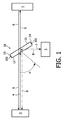
図1は、本発明に従って、超音波トランスデューサ3及び超音波反射によって観測される物体1及び2を有する設定における音響スイッチング装置10の概略図を示す。
FIG. 1 shows a schematic diagram of an
その音響スイッチング装置10は、2つの対向する壁11及び12と、端壁13、14も有するハウジングを含む。そのスイッチング装置10のハウジングは、さらに、流体をそのハウジングの中へ及び/又はそのハウジングの外へと導くことを可能にするために1つ又はそれ以上の開口部101を含む。
The
図1に示されるように、そのハウジングの対向する壁11及び12は、間隙を定める。この対向する壁11、12の間の間隙は、不足した圧力にさらされるか、又は例えば、細い中空管などを通して、スイッチング装置10の1つ又はそれ以上の開口部に接続された注射器によって様々な流体で充填されてもよい。その壁11、12は、例えば、水との適切な音響インピーダンスによって非常に低い音響反射を有するTPXホイルなどの、音響的に透明な材料である。壁11、12は、通常、平行なシートであり、0.5mmの間隙によって分離された50μmの厚さを有してもよい。
As shown in FIG. 1, the opposing
スイッチング装置10のハウジングが気体で充填される場合において、それは、超音波トランスデューサ3からの超音波ビームに対して反射型にされ、その反射角はその入射角に等しい。
In the case where the housing of the
スイッチング装置10は、1つ又はそれ以上の開口部のうちの1つの開口部を通して液体でハウジングを充填することによって超音波ビームに対して透過型にしてもよい。その液体は、例えば、水であってよい。その代わりに、その音響スイッチング装置10は、ハウジングを1つ又はそれ以上の開口部を通して十分に不足した圧力下に置くことによって、超音波に対して透過型にされてもよく、そうすることによって、対向する壁11、12は接触し、互いに結合する。この場合、超音波トランスデューサ3からの超音波ビームは、スイッチング装置10を通って透過させられ、スイッチング装置10の対向する壁11及び12は、その壁11及び12の厚さの合計の厚さを有する単一の音響的に透明な材料として機能する。
The switching
音響スイッチング装置10は、超音波トランスデューサ3と物体1との間において、そのトランスデューサから放射される超音波に沿って配置される。物体2は、超音波スイッチング装置10のすぐ下に、トランスデューサから放射される超音波の縦軸に垂直に配置される。
The
音響スイッチング装置10は、入射する超音波ビーム4が、角度αでその装置の面に当たるように方向付けられ;有利にもαは、45°に等しくてもよく、その場合、反射した超音波ビームもまた45°であり、それに応じて、スイッチング装置10が反射状態にあるとき、すなわち、スイッチング装置10の壁11と12との間の間隙が気体で充填されるとき、物体2を検出することを可能にする。
The
スイッチング装置10が透過状態にあるとき、すなわち、適切な液体で充填されているか、真空又は適切な不足の圧力にさらされているかの何れか一方のとき、超音波ビーム4は、そのスイッチング装置の中を通って透過する。すなわち透過超音波ビーム5である。その透過した超音波ビーム5は、物体1によって反射し、透過状態にあるスイッチング装置10の中を通り抜け、超音波トランスデューサ3へと戻る反射した超音波ビーム6へとなってよい。
When the
スイッチング装置10がそれの反射状態にあるとき、すなわち、空気などの適切な気体で充填されているとき、超音波ビーム4は、そのスイッチング装置10によって反射し、反射した超音波ビーム7へとなる。その反射した超音波ビーム7は、物体2によって反射し、反射状態にあるスイッチング装置10によって反射し、超音波トランスデューサ3へと戻る反射した超音波ビーム8へとなってもよい。
When the
従って、スイッチング装置10の状態によって、物体1又は物体2は、超音波トランスデューサ3からの超音波にさらすことによって観測されてもよい。
Therefore, depending on the state of the
図2は、本発明に従って、超音波カテーテル100の実施形態の概略図を示す。
FIG. 2 shows a schematic diagram of an embodiment of an
カテーテル100は、壁11及び12によって定められるハウジングを含む音響スイッチング装置10を含む。カテーテル100は、外部ケーシング14を含み、それは、壁25と共に、スイッチング装置10のハウジングが配置される筐体15を定義する。カテーテル100は、さらに、リード線21によって電力供給される超音波トランスデューサ20を含む。ケーシング14は、2つのウィンドウW1及びW2を含み、それらは、超音波に対して透過型である。その代わりに、ケーシング14の全ては、音響的に透過型の材料で作られている。しかし、そのケーシングの音響ウィンドウW1及びW2を含まない部分は、他の材料で作られていてもよく、それは、組織治療に対してRFエネルギーを印加するために、導電性の区分を有してもよい。カテーテル先端の筐体15は、例えば塩水などの液体で充填されてもよい。
スイッチング装置10のハウジングは、トランスデューサ20から放射される超音波がスイッチング装置10のハウジングにおいて45°の入射角を有するように、そのトランスデューサの縦軸に沿って約45°の角度で配置される。図2において、透過した超音波ビームは、数字の6で示され、その場合では、音響スイッチング装置10は超音波に対して透明である。すなわち、それは、液体で充填されているか、真空下にある。反射した超音波ビームは、数字の7で示され、その場合では、音響スイッチング装置10は、超音波に対して反射型である。すなわち、それは、空気などの気体で充填されている。
The housing of the
カテーテル100は、従って、そのカテーテルを機械的に動かさずに視野又は撮像視野を変えることができるカテーテルである。カテーテル100の適用の一例は、心房細動治療に対する左心房のアブレーションに関し、RFアブレーション・カテーテルは、処置の間に、その空間的定位をその組織に関して変える。
The
図3は、本発明に従って、超音波カテーテル110のもう1つの実施形態の概略図を示す。
FIG. 3 shows a schematic diagram of another embodiment of an
カテーテル110は、位置の範囲内に配置されるように、機械的に駆動されてもよい音響スイッチング装置を含み、3つの位置が符号10a、10b及び10cで示されている。
カテーテル110は、壁25とともに筐体15を定義する外部ケーシング14を含み、その筐体において、スイッチング装置のハウジングが配置されている。カテーテル110は、リード線21を通して電力供給される超音波トランスデューサ20をさらに含む。ケーシング14は、超音波に対して透過型の2つのウィンドウW1及びW2を含む。その代わりに、ケーシング41の全ては、音響的に透過型の材料で作られていてよい。しかし、そのケーシングの音響ウィンドウW1及びW2を含まない部分は、他の材料で作られていてよく、組織治療に対してRFエネルギーを印加するために、導電性の区分を有してもよい。カテーテルの先端の筐体15は、例えば、塩水などの液体で充填されてもよい。
位置10bにおけるスイッチング装置のハウジングは、トランスデューサ20から放射される超音波気体イッチング装置10のハウジングにおいて45°の入射角を有するように、そのトランスデューサの縦軸に沿って約45°の角度で配置される。図2において、透過した超音波ビームが、数字6で示され、その場合では、音響スイッチング装置10が超音波に対して透明であり、すなわち、液体で充填されているか、又は真空下にある。反射した超音波ビームは、数字7で示され、その場合では、音響スイッチング装置10は、超音波に対して反射型であり、すなわち、空気などの気体で充填されている。位置10a及び10bにおいて、超音波トランスデューサ20からのビームのスイッチング装置10a、10cのハウジングへの入射角は、45°とは異なり、それによって、その超音波ビームは、位置10a、10b、10cにおいてスイッチング装置のハウジングから伝送される超音波ビームにそれぞれ対応する矢印7a、7b、7cによって示されるように、カテーテルの下の物体(図3に示されていない)における角度の範囲に衝突してもよい。
The housing of the switching device at
従って、音響スイッチの限られた機械的駆動で、音響ウィンドウW2に沿って超音波ビームを操作することが可能である。注目すべきは、トランスデューサのアクティブ素子の直径が、その音響スイッチング装置が操作できる位置の範囲によって制限されることである。 Therefore, it is possible to manipulate the ultrasonic beam along the acoustic window W2 with a limited mechanical drive of the acoustic switch. It should be noted that the diameter of the transducer's active element is limited by the range of positions that the acoustic switching device can operate.
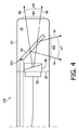
図4は、本発明に従って、超音波カテーテル120のさらにもう1つの実施形態の概略図を示す。
FIG. 4 shows a schematic diagram of yet another embodiment of an
カテーテル120は、音響スイッチング装置10及び外部ケーシング14を含み、そのケーシングは、壁25とともに、スイッチング装置10のハウジングが配置される筐体15を定義する。カテーテル120は、さらに、リード線21を通して電力供給される超音波トランスデューサ20を含む。ケーシング14は、2つのウィンドウW1及びW2を含み、それらは超音波に対して透過型である。その代わりに、ケーシング14の全ては、音響的に透過型の材料で作られてもよい。しかし、そのケーシングの音響ウィンドウW1及びW2を含まない部分は、他の材料で作られてもよく、それは、組織治療に対してRFエネルギーを印加するために導電性の材料を有してもよい。カテーテルの先端の筐体15は、例えば、塩水などの液体で充填されてもよい。
The
この場合もまた、スイッチング装置10は、ハウジングを1つ又はそれ以上の開口部のうちの1つの開口部を通して液体で充填することによって超音波ビームに対して透過型にすることができる。その液体は、例えば、水であってよい。その代わりに、音響スイッチング装置10は、そのハウジングを、対向する壁11及び12が接触し、互いに結合するように、1つ又はそれ以上の開口部を通して十分に不足した圧力にさらすことによって超音波に対して透過型にすることができる。この場合、超音波トランスデューサ3からの超音波ビームは、スイッチング装置10の中を通って透過し、スイッチング装置10の対向する壁11及び12は、それらの厚さの合計の厚さを有する単一の音響的に透明な材料として機能する。
Again, the switching
カテーテル120は、さらに、例えば液体レンズなどのレンズ30を含み、超音波トランスデューサ20から放射される超音波ビームを前方向及び横方向/下方向の構成において大きな領域にまん延させることを可能にする。前方向における領域、すなわち透過した超音波ビーム6aと6bとの間の領域は、図4においてα6で示されている一方、下方向/横方向の領域、すなわち反射した超音波ビーム7aと7bとの間の領域は、図4においてα7で示されている。
The
液体レンズ30は、2つの不混和液の間の界面を使用することによって、ある一定の区分において超音波ビームを走査することを可能にし、それは、エレクトロウェッティングの原理によって操作することができる。その走査区分は、すでに液体レンズによって定義されていることから、音響スイッチは、治療中に望まれる場合はいつでも、それを横方向に投影する。この場合において、そのカテーテルの先端の全体は、望ましくは音響的に透明な材料によって覆われるべきである。
The
図3及び4において開示される実施形態は、そのカテーテルの先端に沿った連続的な走査を得るために、組み合わされてもよい。さらに、単一のピストン・トランスデューサ及び液体レンズを使用する代わりに、位相配列トランスデューサ(多素子)を使用することができる。これは、出力される音響圧力が撮像しきい値に達するときに、特に有利である。この方法では、その走査区分は、位相配列トランスデューサによって供給され、一方、音響スイッチによる横方向/下方向の投影、及び最終的にその機械的操作は、カテーテルにおける大きな視野を保証する。 The embodiments disclosed in FIGS. 3 and 4 may be combined to obtain a continuous scan along the catheter tip. Furthermore, instead of using a single piston transducer and liquid lens, a phased array transducer (multi-element) can be used. This is particularly advantageous when the output acoustic pressure reaches the imaging threshold. In this way, the scan section is supplied by a phased array transducer, while the lateral / downward projection by the acoustic switch, and finally its mechanical manipulation, ensures a large field of view in the catheter.
さらに、これは、液体レンズと組み合わせてもよく、それによって、アレイで横方向のステアリングを実施し、液体レンズで高度のステアリングを実施することによって、3次元(3D)撮像が可能になる。これは、その3次元撮像の大きい視野をもたらす。 In addition, this may be combined with a liquid lens, which enables three-dimensional (3D) imaging by performing lateral steering with the array and advanced steering with the liquid lens. This results in a large field of view for that 3D imaging.
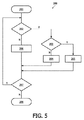
図5は、本発明の超音波に対する音響スイッチング装置の状態を制御する方法200のフローチャートである。そのスイッチング装置は、音響的に透明な材料の2枚のシートを含み、それらのシートは、ハウジングの対向する壁を構成する。
FIG. 5 is a flowchart of a
方法200は、201で開始し202へと持続し、スイッチング装置が透過状態にあるべきかどうかを決定する。ステップ202における決定が、そのスイッチング装置が透過状態にある必要があることを決定する場合、その方法はステップ203へと続き、透過状態が、スイッチング装置のハウジングを、不足した圧力下に置くことによって得られるかが決定される。肯定的な場合、その方法は、ステップ205へと続き、そのスイッチング装置のハウジングが、シートの間に間隙が存在しないようにそれらのシートを互いに接触させるために、十分に不足した圧力下に置かれ、その少なくとも一部分が超音波トランスデューサからの超音波ビームにさらされる。否定的な場合は、その方法は、ステップ203から、スイッチング装置が、そのハウジングを、例えば水などの適切な液体で充填することによって、透過型にされるステップ204へと続く。その方法は、ステップ205又はステップ204の何れか一方から、スイッチング装置のさらなる又は連続した制御が必要であるか否かを決定するステップ207へと続く。肯定的な場合は、その方法は、ステップ202へと戻る;否定的な場合は、その方法は、ステップ208で終了する。
The
ステップ202における決定が否定である場合、つまり、スイッチング装置が透過状態にあるべきでない場合、それは反射状態にあるべきである。この場合において、その方法は、スイッチング装置のハウジングが、音響スイッチを望まれる反射状態にするために、気体で充填されるステップ206へと続く。その結果、その方法は、スイッチング装置のさらなる又は連続した制御が必要であるか否かを決定するステップ207へと続く。肯定的な場合、その方法は、ステップ202へと戻る;否定的な場合、その方法は、ステップ208で終了する。
If the determination in
手短に言えば、本発明は、音響スイッチに関し、超音波伝播方向に対する発想は、その音響スイッチを動かさずに変えることである。そのスイッチング装置は、音響的に透明な材料の2枚のシートを含む。それらのシートは、ハウジングの対向する壁を構成する。スイッチング装置は、さらに、そのハウジングの中へ及び/又は外へ流体を導くことを可能にするために、1つ又はそれ以上の開口部を含む。そのスイッチング装置は、ハウジングを、その1つ又はそれ以上の開口部を通して充填することによって、反射型にしてもよい。さらに、そのスイッチング装置は、そのハウジングを、その1つ又はそれ以上の開口部を通して液体で充填することによって及び/又はそのハウジングをその1つ又はそれ以上の開口部を通して不足した圧力下に置くことによって、超音波に対して透過型にしてもよい。その音響スイッチング装置は、厳密な寸法の制限を有するカテーテル内に適切に適合する。 Briefly, the present invention relates to an acoustic switch, and the idea for the direction of ultrasonic propagation is to change the acoustic switch without moving it. The switching device includes two sheets of acoustically transparent material. These sheets constitute the opposing walls of the housing. The switching device further includes one or more openings to allow fluid to be directed into and / or out of the housing. The switching device may be reflective by filling the housing through its one or more openings. Further, the switching device may cause the housing to fill with liquid through the one or more openings and / or place the housing under insufficient pressure through the one or more openings. Thus, a transmission type may be used for ultrasonic waves. The acoustic switching device fits well within a catheter with strict dimensional limitations.
本発明のスイッチング装置は、例えば、心不整脈の治療中における組織撮像において使用されてもよい。この場合、その処置の間における病班の形成の進行を追跡することが望まれ、そのカテーテルの空間的定位は、その組織に関して垂直から平行に変わる。さらに、本発明のスイッチング装置は、装置の寸法の制限が非常に厳しい侵襲の少ない介入において適用されてもよい。 The switching device of the present invention may be used, for example, in tissue imaging during the treatment of cardiac arrhythmias. In this case, it is desired to follow the progression of lesion formation during the procedure, and the spatial orientation of the catheter changes from vertical to parallel with respect to the tissue. Furthermore, the switching device of the present invention may be applied in a less invasive intervention where the device size limitations are very severe.
本発明は、特定された実施形態に関連して記載されてきたが、本文献で説明された特定の形に限定することは目的としていない。むしろ、本発明の範囲は、添付の請求項によってのみ限定される。請求項において、「含む」という用語は、他の素子又はステップの存在を除外しない。その上、個別の特徴が異なる請求項に含まれているが、これらは、可能ならば有利に組み合わされ、その異なる請求項における包含は、それらの特徴の組み合わせが実現可能でない及び/又は有利であることは示さない。さらに、単一を示す言及は、複数を除外しない。従って、「第1」、「第2」などへの言及は、複数を除外しない。さらに、請求項における参照符号は、その範囲を限定するものとして解釈するべきではない。 Although the present invention has been described in connection with specific embodiments, it is not intended to be limited to the specific form set forth in this document. Rather, the scope of the present invention is limited only by the accompanying claims. In the claims, the term “comprising” does not exclude the presence of other elements or steps. Moreover, although individual features are included in different claims, they are advantageously combined where possible, and inclusion in the different claims is not feasible and / or advantageous in combination of those features. Not shown. Further, references to the single do not exclude a plurality. Accordingly, references to “first”, “second” and the like do not exclude a plurality. Moreover, reference signs in the claims shall not be construed as limiting their scope.
Claims (15)
‐前記音響スイッチング装置を反射状態にするために、前記ハウジングを1つ又はそれ以上の開口部を通して気体で充填するステップ;及び/又は
‐前記音響スイッチング装置を透過状態にするために、前記ハウジングを前記1つ又はそれ以上の開口部を通して不足した圧力下に置くステップ又は該ハウジングを液体で充填するステップ;
のうち1つ又はそれ以上を含む、方法。 A method for controlling the state of an acoustic switching device for ultrasound, the switching device comprising two acoustically transparent sheets, which constitute opposing walls of the housing:
Filling the housing with gas through one or more openings to make the acoustic switching device reflective; and / or Placing under one or more openings under insufficient pressure or filling the housing with liquid;
A method comprising one or more of:
‐請求項1に記載のスイッチング装置;
を含む超音波カテーテル。 An ultrasonic transducer; and a switching device according to claim 1;
Including an ultrasonic catheter.
‐前記音響スイッチング装置を反射状態にするために、前記ハウジングを気体で充填する又は不足した圧力下に置くステップ、又は前記音響スイッチング装置を透過状態にするために、前記ハウジングを液体で充填するステップ、及び
‐前記スイッチング装置を超音波にさらすステップ;
を含む方法。 A method for directing ultrasound from an ultrasound catheter comprising an ultrasound transducer and the acoustic switching device of claim 1:
Filling the housing with a gas or under insufficient pressure to bring the acoustic switching device into a reflective state, or filling the housing with a liquid to put the acoustic switching device into a transmissive state. And-subjecting said switching device to ultrasound;
Including methods.
Applications Claiming Priority (3)
| Application Number | Priority Date | Filing Date | Title |
|---|---|---|---|
| EP08168895.4 | 2008-11-12 | ||
| EP08168895 | 2008-11-12 | ||
| PCT/IB2009/054907 WO2010055443A1 (en) | 2008-11-12 | 2009-11-05 | Acoustical switch and catheter comprising acoustical switch |
Publications (1)
| Publication Number | Publication Date |
|---|---|
| JP2012508593A true JP2012508593A (en) | 2012-04-12 |
Family
ID=41490311
Family Applications (1)
| Application Number | Title | Priority Date | Filing Date |
|---|---|---|---|
| JP2011535194A Withdrawn JP2012508593A (en) | 2008-11-12 | 2009-11-05 | Acoustic switch and catheter with acoustic switch |
Country Status (5)
| Country | Link |
|---|---|
| US (1) | US20110275962A1 (en) |
| EP (1) | EP2346409A1 (en) |
| JP (1) | JP2012508593A (en) |
| CN (1) | CN102215756B (en) |
| WO (1) | WO2010055443A1 (en) |
Families Citing this family (5)
| Publication number | Priority date | Publication date | Assignee | Title |
|---|---|---|---|---|
| US10499937B2 (en) | 2006-05-19 | 2019-12-10 | Recor Medical, Inc. | Ablation device with optimized input power profile and method of using the same |
| US8974445B2 (en) | 2009-01-09 | 2015-03-10 | Recor Medical, Inc. | Methods and apparatus for treatment of cardiac valve insufficiency |
| CN102847238B (en) * | 2011-06-28 | 2015-07-15 | 绵阳索尼克电子有限责任公司 | Ultrasonic treatment device for changing ultrasonic beam radiation direction and method for realizing ultrasonic treatment device |
| EP3643245A1 (en) | 2018-10-25 | 2020-04-29 | Koninklijke Philips N.V. | Intravascular device |
| CN111281428B (en) * | 2020-02-12 | 2021-08-06 | 深圳大学 | Ultrasonic probe for monitoring hemodynamic parameters |
Family Cites Families (7)
| Publication number | Priority date | Publication date | Assignee | Title |
|---|---|---|---|---|
| US3802533A (en) * | 1968-05-20 | 1974-04-09 | Holotron Corp | Improvements in and relating to ultrasonic lenses |
| DE3840077A1 (en) * | 1988-11-28 | 1990-05-31 | Wolf Gmbh Richard | LITHOTRIPTOR |
| JP3860227B2 (en) * | 1993-03-10 | 2006-12-20 | 株式会社東芝 | Ultrasonic therapy device used under MRI guide |
| WO2002005720A1 (en) * | 2000-07-13 | 2002-01-24 | Transurgical, Inc. | Energy application with inflatable annular lens |
| EP1299035B1 (en) * | 2000-07-13 | 2013-02-13 | ReCor Medical, Inc. | Thermal treatment apparatus with focussed energy application |
| CN100476513C (en) * | 2003-07-08 | 2009-04-08 | 皇家飞利浦电子股份有限公司 | Variable focus spectacles |
| US7077808B2 (en) * | 2003-07-31 | 2006-07-18 | Boston Scientific Scimed. Inc. | Ultrasonic imaging catheter |
-
2009
- 2009-11-05 WO PCT/IB2009/054907 patent/WO2010055443A1/en active Application Filing
- 2009-11-05 US US13/127,089 patent/US20110275962A1/en not_active Abandoned
- 2009-11-05 EP EP09759804A patent/EP2346409A1/en not_active Withdrawn
- 2009-11-05 JP JP2011535194A patent/JP2012508593A/en not_active Withdrawn
- 2009-11-05 CN CN2009801451373A patent/CN102215756B/en not_active Expired - Fee Related
Also Published As
| Publication number | Publication date |
|---|---|
| WO2010055443A1 (en) | 2010-05-20 |
| CN102215756B (en) | 2013-08-21 |
| EP2346409A1 (en) | 2011-07-27 |
| CN102215756A (en) | 2011-10-12 |
| US20110275962A1 (en) | 2011-11-10 |
Similar Documents
| Publication | Publication Date | Title |
|---|---|---|
| EP2470099B1 (en) | A catheter for open-loop irrigated ablation of tissue | |
| KR102427579B1 (en) | Ultrasound Imaging and Therapy Devices | |
| US6083159A (en) | Methods and devices for providing acoustic hemostasis | |
| CA2253664C (en) | Methods and devices for providing acoustic hemostasis | |
| JP6943768B2 (en) | Ultrasonic Transducer Array for Ultrasound Thrombosis Treatment and Monitoring | |
| JP5021679B2 (en) | Ultrasound therapy clamp | |
| US7530356B2 (en) | Method and system for noninvasive mastopexy | |
| US20030060736A1 (en) | Lens-focused ultrasonic applicator for medical applications | |
| US20120330197A1 (en) | Noninvasive treatment of blood vessels | |
| JP3373602B2 (en) | Ultrasound therapy equipment | |
| JP2004532689A (en) | Occlusion method using ultrasound for treatment | |
| JP2012508593A (en) | Acoustic switch and catheter with acoustic switch | |
| CN111093461B (en) | Therapeutic ultrasound device and method | |
| JP3850094B2 (en) | Ultrasound diagnostic treatment system and treatment adapter | |
| JP4434668B2 (en) | Treatment system and treatment support system | |
| KR101259381B1 (en) | Applicator for HIFU | |
| JPH10248854A (en) | Ultrasonic treatment device | |
| JPH10127678A (en) | Ultrasonic diagnostic treatment system |
Legal Events
| Date | Code | Title | Description |
|---|---|---|---|
| A621 | Written request for application examination |
Free format text: JAPANESE INTERMEDIATE CODE: A621 Effective date: 20121101 |
|
| A761 | Written withdrawal of application |
Free format text: JAPANESE INTERMEDIATE CODE: A761 Effective date: 20131007 |