JP2012506946A - High pressure electrolytic cell - Google Patents
High pressure electrolytic cell Download PDFInfo
- Publication number
- JP2012506946A JP2012506946A JP2011532557A JP2011532557A JP2012506946A JP 2012506946 A JP2012506946 A JP 2012506946A JP 2011532557 A JP2011532557 A JP 2011532557A JP 2011532557 A JP2011532557 A JP 2011532557A JP 2012506946 A JP2012506946 A JP 2012506946A
- Authority
- JP
- Japan
- Prior art keywords
- cell stack
- cell
- pressure
- electrolysis
- container
- Prior art date
- Legal status (The legal status is an assumption and is not a legal conclusion. Google has not performed a legal analysis and makes no representation as to the accuracy of the status listed.)
- Granted
Links
- 238000005868 electrolysis reaction Methods 0.000 claims abstract description 56
- 238000000034 method Methods 0.000 claims abstract description 19
- 239000012530 fluid Substances 0.000 claims abstract description 15
- 238000007667 floating Methods 0.000 claims abstract description 12
- 230000008602 contraction Effects 0.000 claims abstract description 5
- 239000001257 hydrogen Substances 0.000 claims description 40
- 229910052739 hydrogen Inorganic materials 0.000 claims description 40
- 239000007789 gas Substances 0.000 claims description 39
- UFHFLCQGNIYNRP-UHFFFAOYSA-N Hydrogen Chemical compound [H][H] UFHFLCQGNIYNRP-UHFFFAOYSA-N 0.000 claims description 38
- XLYOFNOQVPJJNP-UHFFFAOYSA-N water Substances O XLYOFNOQVPJJNP-UHFFFAOYSA-N 0.000 claims description 29
- 239000003792 electrolyte Substances 0.000 claims description 25
- QVGXLLKOCUKJST-UHFFFAOYSA-N atomic oxygen Chemical compound [O] QVGXLLKOCUKJST-UHFFFAOYSA-N 0.000 claims description 18
- 239000001301 oxygen Substances 0.000 claims description 18
- 229910052760 oxygen Inorganic materials 0.000 claims description 18
- 238000009826 distribution Methods 0.000 claims description 4
- 239000000047 product Substances 0.000 description 13
- 230000006835 compression Effects 0.000 description 6
- 238000007906 compression Methods 0.000 description 6
- 239000000446 fuel Substances 0.000 description 5
- IJGRMHOSHXDMSA-UHFFFAOYSA-N Atomic nitrogen Chemical compound N#N IJGRMHOSHXDMSA-UHFFFAOYSA-N 0.000 description 4
- 239000007788 liquid Substances 0.000 description 4
- 238000004519 manufacturing process Methods 0.000 description 4
- 239000000463 material Substances 0.000 description 4
- 238000003860 storage Methods 0.000 description 4
- 239000011261 inert gas Substances 0.000 description 3
- 239000012528 membrane Substances 0.000 description 3
- 230000003071 parasitic effect Effects 0.000 description 3
- XKRFYHLGVUSROY-UHFFFAOYSA-N Argon Chemical compound [Ar] XKRFYHLGVUSROY-UHFFFAOYSA-N 0.000 description 2
- CURLTUGMZLYLDI-UHFFFAOYSA-N Carbon dioxide Chemical compound O=C=O CURLTUGMZLYLDI-UHFFFAOYSA-N 0.000 description 2
- 239000002131 composite material Substances 0.000 description 2
- 238000010586 diagram Methods 0.000 description 2
- 150000002431 hydrogen Chemical class 0.000 description 2
- 239000011244 liquid electrolyte Substances 0.000 description 2
- 239000002184 metal Substances 0.000 description 2
- 229910052757 nitrogen Inorganic materials 0.000 description 2
- 238000000926 separation method Methods 0.000 description 2
- MYMOFIZGZYHOMD-UHFFFAOYSA-N Dioxygen Chemical compound O=O MYMOFIZGZYHOMD-UHFFFAOYSA-N 0.000 description 1
- 241001504982 Pepper cryptic virus 1 Species 0.000 description 1
- 241001661006 Pepper cryptic virus 2 Species 0.000 description 1
- 229910052786 argon Inorganic materials 0.000 description 1
- 239000001569 carbon dioxide Substances 0.000 description 1
- 229910002092 carbon dioxide Inorganic materials 0.000 description 1
- 238000001311 chemical methods and process Methods 0.000 description 1
- 239000000470 constituent Substances 0.000 description 1
- 230000006378 damage Effects 0.000 description 1
- 229910001882 dioxygen Inorganic materials 0.000 description 1
- 238000010292 electrical insulation Methods 0.000 description 1
- 239000008151 electrolyte solution Substances 0.000 description 1
- 238000005538 encapsulation Methods 0.000 description 1
- 238000004146 energy storage Methods 0.000 description 1
- 239000000835 fiber Substances 0.000 description 1
- 238000009434 installation Methods 0.000 description 1
- 238000002955 isolation Methods 0.000 description 1
- 238000010030 laminating Methods 0.000 description 1
- 239000012263 liquid product Substances 0.000 description 1
- 239000010445 mica Substances 0.000 description 1
- 229910052618 mica group Inorganic materials 0.000 description 1
- 238000000465 moulding Methods 0.000 description 1
- 239000012811 non-conductive material Substances 0.000 description 1
- 239000011101 paper laminate Substances 0.000 description 1
- 238000010248 power generation Methods 0.000 description 1
- 230000002265 prevention Effects 0.000 description 1
- 239000002990 reinforced plastic Substances 0.000 description 1
- 230000009528 severe injury Effects 0.000 description 1
Images


Classifications
-
- C—CHEMISTRY; METALLURGY
- C25—ELECTROLYTIC OR ELECTROPHORETIC PROCESSES; APPARATUS THEREFOR
- C25B—ELECTROLYTIC OR ELECTROPHORETIC PROCESSES FOR THE PRODUCTION OF COMPOUNDS OR NON-METALS; APPARATUS THEREFOR
- C25B1/00—Electrolytic production of inorganic compounds or non-metals
- C25B1/01—Products
- C25B1/02—Hydrogen or oxygen
- C25B1/04—Hydrogen or oxygen by electrolysis of water
-
- C—CHEMISTRY; METALLURGY
- C25—ELECTROLYTIC OR ELECTROPHORETIC PROCESSES; APPARATUS THEREFOR
- C25B—ELECTROLYTIC OR ELECTROPHORETIC PROCESSES FOR THE PRODUCTION OF COMPOUNDS OR NON-METALS; APPARATUS THEREFOR
- C25B11/00—Electrodes; Manufacture thereof not otherwise provided for
- C25B11/02—Electrodes; Manufacture thereof not otherwise provided for characterised by shape or form
- C25B11/036—Bipolar electrodes
-
- C—CHEMISTRY; METALLURGY
- C25—ELECTROLYTIC OR ELECTROPHORETIC PROCESSES; APPARATUS THEREFOR
- C25B—ELECTROLYTIC OR ELECTROPHORETIC PROCESSES FOR THE PRODUCTION OF COMPOUNDS OR NON-METALS; APPARATUS THEREFOR
- C25B9/00—Cells or assemblies of cells; Constructional parts of cells; Assemblies of constructional parts, e.g. electrode-diaphragm assemblies; Process-related cell features
- C25B9/05—Pressure cells
-
- C—CHEMISTRY; METALLURGY
- C25—ELECTROLYTIC OR ELECTROPHORETIC PROCESSES; APPARATUS THEREFOR
- C25B—ELECTROLYTIC OR ELECTROPHORETIC PROCESSES FOR THE PRODUCTION OF COMPOUNDS OR NON-METALS; APPARATUS THEREFOR
- C25B9/00—Cells or assemblies of cells; Constructional parts of cells; Assemblies of constructional parts, e.g. electrode-diaphragm assemblies; Process-related cell features
- C25B9/70—Assemblies comprising two or more cells
- C25B9/73—Assemblies comprising two or more cells of the filter-press type
- C25B9/75—Assemblies comprising two or more cells of the filter-press type having bipolar electrodes
-
- Y—GENERAL TAGGING OF NEW TECHNOLOGICAL DEVELOPMENTS; GENERAL TAGGING OF CROSS-SECTIONAL TECHNOLOGIES SPANNING OVER SEVERAL SECTIONS OF THE IPC; TECHNICAL SUBJECTS COVERED BY FORMER USPC CROSS-REFERENCE ART COLLECTIONS [XRACs] AND DIGESTS
- Y02—TECHNOLOGIES OR APPLICATIONS FOR MITIGATION OR ADAPTATION AGAINST CLIMATE CHANGE
- Y02E—REDUCTION OF GREENHOUSE GAS [GHG] EMISSIONS, RELATED TO ENERGY GENERATION, TRANSMISSION OR DISTRIBUTION
- Y02E60/00—Enabling technologies; Technologies with a potential or indirect contribution to GHG emissions mitigation
- Y02E60/30—Hydrogen technology
- Y02E60/36—Hydrogen production from non-carbon containing sources, e.g. by water electrolysis
Abstract
電気分解セル積層体(101)を圧力容器(115)の内部に備えている電解槽(100)であって、前記セル積層体の第1の終端プレート(107a)が、前記圧力容器の閉じた両端のうちの一方と一体であって、流体および電気の接続部を備える前記セル積層体の固定のヘッド(107)を形成しており、前記セル積層体の第2の終端プレート(108a)が、前記容器の内部にあって、熱膨張または熱収縮に応答して長手方向に自由に移動でき、すなわち前記積層体の浮動のヘッド(108)を形成している電解槽(100)。圧力容器(115)は、好ましくは、電気分解のプロセスにおいて得られる気体生成物を使用して加圧される。An electrolytic cell (100) having an electrolysis cell stack (101) inside a pressure vessel (115), wherein the first end plate (107a) of the cell stack is closed in the pressure vessel. The cell stack is formed as a fixed head (107) that is integral with one of the ends and includes fluid and electrical connections, and a second end plate (108a) of the cell stack includes An electrolytic cell (100) which is inside the container and is free to move longitudinally in response to thermal expansion or contraction, ie forming a floating head (108) of the laminate. The pressure vessel (115) is preferably pressurized using a gaseous product obtained in the process of electrolysis.
Description
本発明は、とりわけ水の電気分解のための電解槽の分野に関する。さらに詳しくは、本発明は、高圧下での動作のために圧力容器の内部にセル積層体を備えている電解槽に関する。 The invention relates in particular to the field of electrolysers for the electrolysis of water. More specifically, the present invention relates to an electrolytic cell provided with a cell stack inside a pressure vessel for operation under high pressure.
電気分解は、化学的に結合した元素を分離するための周知のプロセスである。このプロセスを、電気分解の生成物を或る圧力にて得ることが所望される場合に、そのような圧力のもとで動作させることができる。 Electrolysis is a well-known process for separating chemically bound elements. This process can be operated under such pressure if it is desired to obtain the product of electrolysis at a certain pressure.
電気分解の最も一般的な用途の1つは、水の電気分解による水素(H2)の生成であり、本明細書においては、以後、この本発明の好ましい用途について言及する。 One of the most common uses of electrolysis is the production of hydrogen (H 2 ) by electrolysis of water, and this specification will be referred to hereinafter for this preferred use of the invention.
水の電気分解による水素の生成は、化学プロセスの目的のために、最大約30barの圧力において周知である。しかしながら、近年では、はるかに高い圧力の水素の生成の必要が生じている。 The production of hydrogen by electrolysis of water is well known at pressures up to about 30 bar for chemical process purposes. In recent years, however, there has been a need for the production of much higher pressure hydrogen.
水素は、エネルギの貯蔵および運搬のための最良の候補であり、とりわけ再生可能なエネルギ源からの分散発電ならびに水素燃料の車両または燃料電池車両の動作のための最良の候補である。しかしながら、燃料またはエネルギ担体として使用される水素の貯蔵は、例えば200barまたはそれ以上のきわめて高い圧力を必要とする。現時点において、燃料水素の貯蔵について適切な圧力は、350bar(5000psi)または700bar(10.000psi)であると考えられる。水素をこのようなきわめて高い圧力へと圧縮するためには、高価な多段の圧縮機が必要であり、多量のエネルギが消費される。したがって、上述の圧力の水素を直接的に生成することができる電気分解について、強いニーズが存在している。 Hydrogen is the best candidate for energy storage and transport, especially the best candidate for distributed power generation from renewable energy sources and the operation of hydrogen fueled vehicles or fuel cell vehicles. However, storage of hydrogen used as a fuel or energy carrier requires very high pressures, for example 200 bar or higher. At present, a suitable pressure for fuel hydrogen storage is believed to be 350 bar (5000 psi) or 700 bar (10.000 psi). In order to compress hydrogen to such an extremely high pressure, an expensive multistage compressor is required, and a large amount of energy is consumed. Therefore, there is a strong need for electrolysis that can directly generate hydrogen at the pressure described above.
US 4,758,322が、電解槽の周知の構造、いわゆるフィルタプレス構成を開示している。いくつかのバイポーラセルが直列に積層され、タイロッドによって互いに接続された2枚のエンドプレートの間に一体に配置されている。各々のバイポーラセルが、アノード室およびカソード室をダイアフラムまたは膜によって隔てて備えている。次いで、各セルが、2つの面に反対の極性を有している導電壁(いわゆる、バイポーラプレート)によって次のセルから隔てられている。セルの積層が、端部プレートによって一体に固定され、これらの端部プレートが、この積層のアノード(+)およびカソード(−)端子接続部を形成する。端部プレートは、セルの短絡を防止すべく電気的に絶縁されたタイロッドによって、互いに押し付けられている。液体電解質がセルへと導入され、生成される気体がセルから集められる。 US 4,758,322 discloses the well-known structure of an electrolytic cell, the so-called filter press configuration. Several bipolar cells are stacked in series and are integrally arranged between two end plates connected to each other by tie rods. Each bipolar cell comprises an anode chamber and a cathode chamber separated by a diaphragm or membrane. Each cell is then separated from the next by conductive walls (so-called bipolar plates) having opposite polarities on the two faces. The stack of cells is secured together by end plates that form the anode (+) and cathode (−) terminal connections of the stack. The end plates are pressed together by tie rods that are electrically isolated to prevent cell shorting. A liquid electrolyte is introduced into the cell and the gas produced is collected from the cell.
この電解槽は、内部の圧力のもとでの動作、すなわち加圧された電解質および生成ガスにおける動作の能力が、限られている。実際、セルのフレームおよびセル積層体の端部プレートが、内部と通常は大気圧である外部との間の圧力差の全体(Δp)に耐えなければならない。或るΔpを超えると、セルのフレームが機械的な応力に耐えられないだけでなく、セルのフレームのガスケットが電解質またはガスの漏れを防止することができず、実際のところ、この電解槽は、数10barの内圧に限られる。 This electrolyzer has a limited ability to operate under internal pressure, i.e. in pressurized electrolyte and product gas. In fact, the cell frame and the end plate of the cell stack must withstand the entire pressure difference (Δp) between the interior and the exterior, which is usually atmospheric pressure. Beyond a certain Δp, not only does the cell frame cannot withstand mechanical stress, but the cell frame gasket cannot prevent leakage of electrolytes or gases, , Limited to an internal pressure of several tens bar.
この問題を克服するために、別の種類の加圧電解槽が提案されている。その基本的な考え方は、セル積層体を加圧容器の内部で動作させ、このセル積層体の内圧を平衡させることである。 In order to overcome this problem, another type of pressurized electrolytic cell has been proposed. The basic idea is to operate the cell stack inside the pressurized container and to balance the internal pressure of the cell stack.
US 6,153,083が、圧力のもとでの水の電気分解のための電解槽であって、すでに述べたフィルタプレス構成に対応するバイポーラセルの積層体が圧力容器に囲まれている電解槽を開示している。積層体の2つの端部電極が、圧力容器を貫通して延びる2本の引き込みケーブルによって電力源へと接続され、圧力容器の内部は、セル積層体を囲む加圧水で満たされている。しかしながら、詳しくは記載されていないが、実際には解決がきわめて困難であるこの設計の欠点は、加圧容器を貫くケーブルの通路、ならびにアルカリ電解質をセル積層体の内部へと供給するための装置、および積層体によってもたらされる水素および酸素ガスを集めるための装置である。実際には、圧力容器を貫いて入力/出力を設ける必要があり、そこでは気密が重要であり、いかなる漏れも電解槽の動作を損なう可能性がある。特には、容器内の圧力の低下が、多くの場合に、内部の電解槽に回復不可能な損傷を生じさせかねない。さらには、この設計は、最大30barまでの圧力に使用されており、上述のような水素の貯蔵には不充分である。 US 6,153,083 is an electrolytic cell for electrolysis of water under pressure, in which a bipolar cell stack corresponding to the filter press configuration already described is enclosed in a pressure vessel A tank is disclosed. Two end electrodes of the stack are connected to a power source by two lead-in cables extending through the pressure vessel, and the interior of the pressure vessel is filled with pressurized water surrounding the cell stack. However, although not described in detail, the disadvantages of this design, which are very difficult to solve in practice, are the cable passages through the pressurized vessel, as well as an apparatus for supplying alkaline electrolyte to the interior of the cell stack. , And an apparatus for collecting hydrogen and oxygen gas provided by the stack. In practice, it is necessary to provide an input / output through the pressure vessel, where airtightness is important and any leakage can impair the operation of the electrolyzer. In particular, a drop in pressure within the container can often cause irreparable damage to the internal electrolytic cell. Furthermore, this design is used for pressures up to 30 bar and is not sufficient for hydrogen storage as described above.
別のカプセル化の技法が、DE 44 18 999に開示されている。セルブロックが、圧力管によって囲まれており、圧力管の両端が、2つのそれぞれのフランジによって閉じられており、2つのフランジは、セルブロックの端部カバーでもあり、したがって電気分解セルへの流体の出入りのための必要な接続部が設けられている。圧力管の内部かつセルブロックの外部の空間は、電気分解セルへの電解質の供給による水圧のもとに置かれている。同じ長さを有するように強いられるセルブロックと容器との間の膨張の差を補償するために、セルのフレーム(非導電性材料からなる)が、平坦な弾性ガスケットと交互にされている。この設計は、前記ガスケットの気密性に弱点を有しているほか、導電性の電解質が加圧流体として使用されていることで、セルの漏れの場合の短絡の恐れが増している。 Another encapsulation technique is disclosed in DE 44 18 999. The cell block is surrounded by a pressure tube, and both ends of the pressure tube are closed by two respective flanges, which are also the end covers of the cell block and thus the fluid to the electrolysis cell Necessary connections for entering and exiting are provided. The space inside the pressure tube and outside the cell block is placed under water pressure by supplying electrolyte to the electrolysis cell. In order to compensate for the difference in expansion between the cell block and the container that are forced to have the same length, the cell frame (made of non-conductive material) is alternated with a flat elastic gasket. This design has a weak point in the gas tightness of the gasket, and the use of a conductive electrolyte as the pressurized fluid increases the risk of short circuits in the case of cell leakage.
従来技術の別の問題は、容器または圧力管の熱膨張が、内部のセル積層体の熱膨張と比べて異なることであり、これが、電解質の漏れおよび放出の危険を伴う機械的な応力の原因となりうる。水による加圧系においては、たとえ少量の電解質の漏れでも、水が導電性となって電気の分路および寄生電流ならびに関連の電力損失が生じ、あるいは短絡およびセル積層体の深刻な損傷さえ生じるため、致命的である。 Another problem with the prior art is that the thermal expansion of the vessel or pressure tube is different compared to the thermal expansion of the internal cell stack, which causes mechanical stress with the risk of electrolyte leakage and release. It can be. In pressurized systems with water, even a small amount of electrolyte leakage can make the water conductive and cause electrical shunting and parasitic currents and associated power losses, or even severe damage to the cell stack and cell stack Because it is fatal.
したがって、従来技術の欠点を、以下のように要約することができる。公知の加圧電解槽のいくつかは、ガスの大量貯蔵という目的にとって妥当な水素の比体積の縮小に必要なレベルをはるかに下回る圧力でしか動作することができず、特には圧力容器を貫く流体および電気の接続部が、系の気密性にとってきわめて重要であり、一般的な加圧媒体としての水の使用は、電解質の漏れの場合の寄生電流および危険な短絡の恐れを依然として残し、代わりに容器を加圧するために電解質を使用すると、上述の理由でさらに危険である。水の電気分解に関して述べたこれらの欠点は、他の用途にも一般的にあてはまる。 Therefore, the drawbacks of the prior art can be summarized as follows. Some of the known pressurized electrolyzers can only operate at pressures well below the level required to reduce the specific volume of hydrogen that is reasonable for the purpose of mass storage of gas, especially through pressure vessels. Fluid and electrical connections are critical to the tightness of the system, and the use of water as a common pressurized medium still leaves the risk of parasitic currents and dangerous shorts in the case of electrolyte leakage, instead Using an electrolyte to pressurize the container is even more dangerous for the reasons described above. These drawbacks mentioned with respect to water electrolysis are also generally applicable to other applications.
本発明の根底にある課題は、上述の限界を克服するように構成された加圧セル積層体電解槽の構造を提供することにあり、特には燃料またはエネルギ担体としての水素の使用に必要な高い圧力で水から水素を安全かつ確実に生成することにある。 The problem underlying the present invention is to provide a structure of a pressurized cell stack electrolyzer configured to overcome the above-mentioned limitations, particularly necessary for the use of hydrogen as a fuel or energy carrier. It is to produce hydrogen safely and reliably from water at high pressure.
この課題が、
外殻と閉じた両端部とを有している圧力容器、
前記圧力容器の内部に位置し、複数のバイポーラ電気分解セルを第1および第2の終端プレートの間に積層して備えており、内圧のもとで動作するように構成されている電気分解セル積層体、ならびに
前記セル積層体へと電解質を供給するための流体接続部、前記セル積層体から電気分解の生成物を集めるための流体接続部、および少なくともアノードおよびカソード接続部を含む電気接続部
を備えている電解槽であって、
前記セル積層体の第1の終端プレートが、前記圧力容器の前記閉じた両端部のうちの一方に一体化し、前記セル積層体の固定のヘッドを形成しており、
該固定のヘッドに、前記セル積層体との前記流体接続部ならびにアノードおよびカソード電気接続部が備えられ、
前記セル積層体の第2の終端プレートが、前記容器の内部に位置し、熱膨張または熱収縮に応答して前記第1の終端プレートおよび前記容器に対して長手方向に自由に移動でき、すなわち前記セル積層体の浮動のヘッドを形成している
ことを特徴とする電解槽によって解決される。
This challenge is
A pressure vessel having an outer shell and closed ends,
An electrolysis cell located inside the pressure vessel, comprising a plurality of bipolar electrolysis cells stacked between the first and second end plates, and configured to operate under internal pressure Stack, and fluid connection for supplying electrolyte to the cell stack, fluid connection for collecting electrolysis products from the cell stack, and electrical connection including at least anode and cathode connections An electrolytic cell comprising:
A first end plate of the cell stack is integrated with one of the closed ends of the pressure vessel to form a fixed head of the cell stack;
The fixed head is provided with the fluid connection with the cell stack and the anode and cathode electrical connections;
A second end plate of the cell stack is located inside the container and is free to move longitudinally with respect to the first end plate and the container in response to thermal expansion or contraction, i.e. This is solved by an electrolytic cell characterized in that it forms a floating head of the cell stack.
本発明の好ましい実施の形態においては、前記閉じた端部が、片側においてはカバーであり、反対側においては前記セル積層体の第1の終端プレートも構成する平たい端部カバーまたは真っ直ぐなフランジ(dead flange)である。 In a preferred embodiment of the present invention, the closed end is a cover on one side and on the opposite side a flat end cover or straight flange (which also constitutes the first end plate of the cell stack). dead flag).
好ましい特徴によれば、前記アノードおよびカソード電気接続部が、好ましくはタイロッドの形態であり、前記第1の終端プレートを貫通するとともに、該プレートから絶縁されており、前記積層体の第1のセル(すなわち、前記固定のヘッドにより近いセル)へと電気的に接続されている少なくとも第1の電気コネクタと、前記第1の終端プレートに組み合わせられ、該プレートに電気的に接続されている少なくとも第2の電気コネクタとを含んでおり、前記第1の終端プレートが、前記第2の終端プレートに電気的に接続されている。例えば、前記第1の電気コネクタが、正であって、前記第1のセルへとアノード電流を運び、前記第2の電気コネクタが、負であって、前記積層体の最後のセルのカソード末端の役割を有している。 According to a preferred feature, the anode and cathode electrical connections are preferably in the form of tie rods, penetrate the first end plate and are insulated from the plate, the first cell of the stack (Ie, at least a first electrical connector electrically connected to the cell closer to the fixed head) and at least a first electrical connector coupled to and electrically connected to the first termination plate The first end plate is electrically connected to the second end plate. For example, the first electrical connector is positive and carries anode current to the first cell, and the second electrical connector is negative and the cathode end of the last cell of the stack. Has the role of
好ましい実施例においては、前記セル積層体の前記終端プレートが、これら2つのプレートの間に機械的および電気的な接続をもたらすタイロッドによって一体にされている。 In a preferred embodiment, the end plate of the cell stack is united by a tie rod that provides a mechanical and electrical connection between the two plates.
本発明の好ましい実施の形態によれば、電解槽の全体が、浮動のヘッドと同じ極性および電位になり、電気接続部(アノード/カソード)のうちの1つだけを、容器の外殻またはいずれかのカバーを貫いて電解槽の内部から取り出せばよい。例えば、負の電気接続部を構成するタイロッドが、固定のヘッド(内部の浮動のヘッド、したがってセル積層体の終端プレートへと、タイロッドによって電気的および機械的に接続されている)を形成している閉じた端部へと取り付けられ、絶縁されたタイロッドが、浮動のヘッドを貫通して積層体の第1の端部プレートへの正の電気接続部をもたらす。 According to a preferred embodiment of the present invention, the entire electrolytic cell is of the same polarity and potential as the floating head, and only one of the electrical connections (anode / cathode) is connected to the outer shell of the container or any The cover may be taken out from the inside of the electrolytic cell. For example, the tie rods that make up the negative electrical connection form a fixed head (electrically and mechanically connected by a tie rod to the inner floating head and hence the end plate of the cell stack). Attached to the closed end and an insulated tie rod provides a positive electrical connection through the floating head to the first end plate of the laminate.
本発明の別の態様によれば、前記容器が、従来技術のように液体によってではなく、ガスによって圧力のもとに保たれる。したがって、本発明の一態様は、圧力容器と、該圧力容器の内部の電気分解セル積層体とを備えており、前記セル積層体が、複数のバイポーラ電気分解セルを第1および第2の終端プレートの間に積層して備えている電解槽であって、前記容器がガスによって加圧されることを特徴とする電解槽である。 According to another aspect of the invention, the container is kept under pressure by a gas rather than by a liquid as in the prior art. Accordingly, one aspect of the present invention includes a pressure vessel and an electrolysis cell stack inside the pressure vessel, and the cell stack includes a plurality of bipolar electrolysis cells as first and second terminals. An electrolytic cell provided by laminating between plates, wherein the container is pressurized with gas.
容器を加圧するガスは、電気分解のプロセスに関与しても、関与しなくてもよい。より具体的には、容器を加圧するガスが、例えば不活性ガスであり、すなわち電気分解のプロセスに関して不活性な性質を有しており、あるいは代案として、電気分解のプロセスそのものにおいて圧力のもとで生成されるガスである。好ましくは、ガスが、該ガスを中間の圧縮を必要とせずに容器の加圧に使用できるよう、容器内の圧力レベルよりも高くてよい圧力で前記セル積層体において実行される電気分解プロセスから得られる。 The gas that pressurizes the container may or may not be involved in the electrolysis process. More specifically, the gas that pressurizes the container is, for example, an inert gas, i.e., has an inert property with respect to the electrolysis process, or alternatively, under pressure in the electrolysis process itself. It is a gas produced by Preferably, from an electrolysis process performed in the cell stack at a pressure that may be higher than the pressure level in the container so that the gas can be used to pressurize the container without requiring intermediate compression. can get.
本発明による電気分解のための設備は、
圧力容器の内部にセル積層体を備えており、該セル積層体が、圧力のもとで少なくともガス生成物をもたらすように構成されている電解槽、
前記ガス生成物を受け取り、該ガス生成物を混入している電解質から分離するように構成された少なくとも1つの容器、および
前記ガス生成物の少なくとも一部を加圧媒体として前記圧力容器へと供給する流通配管
を備えている。
The equipment for electrolysis according to the invention comprises:
An electrolytic cell comprising a cell stack inside a pressure vessel, the cell stack configured to provide at least a gas product under pressure;
At least one container configured to receive the gas product and separate from the electrolyte in which the gas product is mixed, and supply at least a portion of the gas product to the pressure container as a pressurized medium It has a distribution pipe.
好ましくは、本発明によるガス加圧式の電解槽において、前記セル積層体は、固定のヘッドおよび浮動のヘッドを有する上述の構成を有している。すなわち、前記セル積層体の前記第1の終端プレートが、前記圧力容器の端部カバーのうちの一方と一体であり、すなわち前記セル積層体へと電解質を供給するため、および電気分解の生成物を集めるための適切な流体接続部と、前記セル積層体とのアノードおよびカソード電気接続部とを備える固定のヘッドを形成しており、前記第2の終端プレートが、熱膨張および熱収縮に応答して前記第1の終端および前記容器に対して長手方向に移動でき、すなわち浮動のヘッドを構成している。 Preferably, in the gas pressurization type electrolytic cell according to the present invention, the cell laminate has the above-described configuration having a fixed head and a floating head. That is, the first end plate of the cell stack is integral with one of the end covers of the pressure vessel, i.e. for supplying electrolyte to the cell stack and the product of electrolysis Forming a fixed head with suitable fluid connections for collecting the fluid and anode and cathode electrical connections to the cell stack, the second end plate being responsive to thermal expansion and contraction Thus, it can move longitudinally with respect to the first end and the container, i.e. constitutes a floating head.
ここで、好ましい水の電気分解への応用について述べると、チッ素または水の電気分解に対して不活性である任意の他のガスを、本発明によるガス加圧式電解槽において加圧媒体として使用することができる。第2の選択肢においては、少なくとも前記セル積層体によって圧力のもとでもたらされる水素の一部または酸素の一部が、容器の加圧に使用される。動作時のセル積層体の内圧は、好ましくは少なくとも30barであり、より好ましくは100barよりも高く、さらにより好ましくは100〜700barの範囲である。 Referring now to the preferred water electrolysis application, nitrogen or any other gas that is inert to water electrolysis is used as the pressurizing medium in the gas pressurized electrolyzer according to the invention. can do. In the second option, at least a portion of hydrogen or a portion of oxygen provided under pressure by the cell stack is used to pressurize the container. The internal pressure of the cell stack during operation is preferably at least 30 bar, more preferably higher than 100 bar, even more preferably in the range of 100 to 700 bar.
本発明の好ましい実施の形態による水の電気分解のための設備は、
圧力容器の内部にセル積層体を備えており、該セル積層体が、圧力のもとで水素および酸素をもたらすように構成されている電解槽、
前記電解槽において生成された水素を受け取り、該水素を混入している電解質から分離するように構成された分離容器、および前記電解槽において生成された酸素を受け取り、該酸素を混入している電解質から分離するように構成されたもう1つの分離容器、ならびに
少なくとも前記水素の一部または前記酸素の一部を加圧媒体として前記それぞれの容器から前記圧力容器へと供給する流通配管
を少なくとも備えている。水の電気分解のためのこの設備の電解槽は、好ましくは、固定のヘッドおよび浮動のヘッドを有する上述の構成を有している。
An installation for water electrolysis according to a preferred embodiment of the present invention comprises:
An electrolytic cell comprising a cell stack inside a pressure vessel, the cell stack configured to provide hydrogen and oxygen under pressure;
A separation container configured to receive hydrogen generated in the electrolytic cell and separate it from an electrolyte mixed with the hydrogen, and an electrolyte that receives oxygen generated in the electrolytic cell and mixed with the oxygen Another separation container configured to separate from each other, and at least a distribution pipe for supplying at least a part of the hydrogen or the part of the oxygen as a pressurized medium from the respective container to the pressure container. Yes. The electrolyzer of this facility for water electrolysis preferably has the above-described configuration with a fixed head and a floating head.
圧力を、例えば、2つの容器の間のΔpに反応し、あるいは加圧媒体(水素または酸素)が取り出されるそれぞれの容器に混入した電解質のレベルを一定に保つ差圧コントローラによって、制御することができる。 The pressure can be controlled, for example, by a differential pressure controller that reacts to Δp between the two containers or keeps the level of electrolyte entrained in each container from which the pressurized medium (hydrogen or oxygen) is removed. it can.
本発明の上述のすべての実施の形態において、セル積層体における流体の漏れの阻止は、好ましくはEP 0212240の開示にしたがって得られる。各々のバイポーラセルは、分離要素およびバイポーラ要素と呼ばれる2つの構成要素を、ダイアフラムまたは膜とバイポーラプレートとを内部に保持するフレームの形態に有している。フレームは、好ましくは、内圧に耐えるために円形であり、補強入りのプラスチックで成型され、結果として非導電性である。気密は、Oリングガスケットによって単純に得られ、積層体のフィルタプレス構成を完成させるタイロッドおよび関連の端部カバーにきわめてわずかな負荷しか求めない。液体電解質および生成ガスは、フレーム内に成型され、終端の金属プレートのうちの一方にて終わるチャネルによって、セルへと分配およびセルから収集される。 In all the above embodiments of the present invention, prevention of fluid leakage in the cell stack is preferably obtained according to the disclosure of EP 0212240. Each bipolar cell has two components, called isolation elements and bipolar elements, in the form of a frame that holds a diaphragm or membrane and a bipolar plate therein. The frame is preferably circular in order to withstand internal pressure, is molded of reinforced plastic, and as a result is non-conductive. Hermeticity is simply obtained with an O-ring gasket and requires very little load on the tie rods and associated end covers that complete the filter press configuration of the laminate. Liquid electrolyte and product gas are distributed into and collected from the cell by a channel that is molded into the frame and terminates in one of the terminal metal plates.
フレームは比較的薄く、数ミリメートルの範囲であり、きわめて薄くて柔らかい電極によって占められる各セルのカソードおよびアノード室も同様である。成型技法により、短時間でフレームの大きな連なりを製造することができる。さらには、異なるサイズのフレームを、異なる容量のセルを製造するために容易に成型することが可能である。セルの高い電流密度および小さなサイズが、きわめてコンパクトな構成を可能にし、結果として電気分解プラントを完全に組み立ててから出荷することが可能である。 The frame is relatively thin, in the range of a few millimeters, as are the cathode and anode chambers of each cell occupied by very thin and soft electrodes. A large series of frames can be produced in a short time by the molding technique. Furthermore, different sized frames can be easily molded to produce cells of different capacities. The high current density and small size of the cell allows for a very compact configuration, so that the electrolysis plant can be fully assembled before shipment.
本発明は、従来技術よりもはるかに高い圧力で電気分解のプロセスを安全かつ確実に実行できるようにする多数の利点を有している。本発明は、30bar(実質的に従来技術の限界である)を優に超える圧力のガス生成物を得ることを可能にし、特には本発明は、水素燃料の車両が必要とするような数百barの圧力そのもので水の電気分解からH2を生成するために適している。水素を使用の圧力で電気分解から直接得ることができるため、圧縮に関するコストが節約または大幅に削減され、燃料またはエネルギ担体としての水素の使用が、より魅力的になる。 The present invention has numerous advantages that allow the process of electrolysis to be performed safely and reliably at much higher pressures than the prior art. The present invention makes it possible to obtain a gas product with a pressure well above 30 bar (substantially the limits of the prior art), in particular the present invention provides hundreds as required by hydrogen fueled vehicles. It is suitable for generating H 2 from the electrolysis of water at the bar pressure itself. Since hydrogen can be obtained directly from electrolysis at the pressure of use, the cost associated with compression is saved or significantly reduced, and the use of hydrogen as a fuel or energy carrier becomes more attractive.
固定のヘッドと浮動のヘッドとを有するセル積層体は、浮動のヘッドが容器の外殻に堅固に組み合わせられているのではなく、むしろ熱膨張のもとで自由に動くことができるため、積層体と収容容器との間の熱による伸びの相違の問題を解決する。さらには、本発明によれば、電気接続部を固定のヘッドにおいて得ることができるため、もはや容器の外殻またはカバーを貫く電気接続部(系の気密にとって重要な地点となる)を設ける必要がない。本発明のさらなる利点は、後述のように、運転員への事故を防止すべく電解槽全体の安全な接地が保証されることにある。 Cell stacks with a fixed head and a floating head are not laminated because the floating head is not rigidly coupled to the outer shell of the container, but rather can move freely under thermal expansion. Solves the problem of thermal elongation differences between the body and the containment vessel. Furthermore, according to the present invention, since the electrical connection can be obtained at a fixed head, it is no longer necessary to provide an electrical connection (which is an important point for the tightness of the system) that penetrates the outer shell or cover of the container. Absent. A further advantage of the present invention is that, as will be described later, safe grounding of the entire electrolytic cell is ensured to prevent accidents to the operator.
気体の加圧媒体を使用することで、より良好な電気絶縁が維持され、電解質の漏れによって引き起こされる電力の損失または短絡の恐れが少なくなる。従来技術の水による加圧の系では、積層体からの漏れに起因して電解質がわずかに失われるだけで、容器を加圧している水が導電性になり、積層体および容器に関する寄生電流を助長する可能性がある。水圧が電解質によって直接もたらされる場合には、電解質の溶液が水よりもはるかに導電性であるため、はるかに有害な結果が生じうる。 By using a gaseous pressurized medium, better electrical insulation is maintained and there is less risk of power loss or short circuit caused by electrolyte leakage. In the prior art water pressurization system, only a small amount of electrolyte is lost due to leakage from the laminate, the water pressurizing the container becomes conductive, and parasitic currents on the laminate and the container are reduced. There is a possibility to encourage. If the water pressure is provided directly by the electrolyte, the electrolyte solution is much more conductive than water and can have much more harmful consequences.
プロセスそのものにおいて生成されるガスを加圧媒体として使用することは、外部の圧縮ユニットが不要であるというさらなる利点を有する。セル積層体によってもたらされるガス(例えば、水の電気分解における水素または酸素)を、セル積層体の出力と圧力容器への入り口との間に中間の圧縮を備えることなく、あるいははるかに安価な圧縮(例えば、多段の代わりに1段)だけを備えて、容器へと送ることができる。さらには、5000psi以上で動作するきわめて高い圧力の電解槽に関しては、不活性ガスがそのような圧力レベルでは市販されておらず、追加の高価なガス圧縮システムを設ける必要があると考えられる。 The use of the gas produced in the process itself as a pressurized medium has the further advantage that no external compression unit is required. Gas produced by the cell stack (eg hydrogen or oxygen in the electrolysis of water), without intermediate compression between the cell stack output and the inlet to the pressure vessel, or much cheaper compression (E.g., one stage instead of multiple stages) can be provided and sent to the container. Furthermore, for very high pressure electrolyzers operating at 5000 psi and above, inert gas is not commercially available at such pressure levels, and it may be necessary to provide an additional expensive gas compression system.
他の利点は、低い圧力での電気分解プロセスの開始から最終的な動作圧力まで、電解槽の圧力容器のガスによる加圧が、電気分解プロセスの圧力の高まりに従って比例的に増大する点にある。 Another advantage is that from the start of the electrolysis process at low pressure to the final operating pressure, the pressurization of the electrolyzer pressure vessel with gas increases proportionally with increasing pressure in the electrolysis process. .
図1を参照すると、電解槽100が、セル積層品101を動作時に内部が気相によって加圧される圧力容器115内に囲むことによって構成されている。容器は、両端が閉じられた横向きの円筒形の外殻によって形成され、一方の端部が、フランジ式のカバーであり、第2の端部は、平坦または皿状のフランジ式のカバーまたは一体化された端部である。第2の端部の好ましい実施の形態は、皿状の端部であって、円筒形の外殻へと溶接される。容器の構成材料は、金属または複合材料(例えば、繊維補強品)であってよい。
Referring to FIG. 1, an
セル積層体101は、ダイアフラムまたは膜104によって隔てられたアノード102およびカソード103をそれぞれが備えているバイポーラセルによって形成されている。次いで、各セルが、バイポーラプレート105によって次のセルから隔てられている。セルは、電解質の分配のためのチャネル113と、電気分解の生成物を集めるためのさらなるチャネル114とを収容しているフレーム106を有している。
The
本発明によれば、セル積層体101の第1の終端プレート107aが、圧力容器の端部プレートカバーと一体である一方で、セル積層体101の第2の端部プレート108aは、熱膨張および熱収縮に応答してプレート107aおよび容器115の外殻に対して容器の内部で長手方向に可動である。すなわち、端部プレート107aが、セル積層体101の固定のヘッド107を形成する一方で、反対側の端部プレート108aは、同じセル積層体の浮動のヘッド108を形成する。
According to the present invention, the
固定のヘッド107は、セル積層体へと電解質を供給するための流体接続部および電気分解の生成物を集めるための流体接続部を備えており、セル積層体とのアノードおよびカソード電気接続部も備えている。
The fixed
再び図1の実施の形態に目を向けると、積層体101のすべてのプロセス接続部122は、気体および液体にかかわらず、プレート107aにまとめられており、積層体を容器115の内部で自由に膨張できるようにしている。
Turning again to the embodiment of FIG. 1, all
アノード接続部は、プレート107aを貫通し、ブシュ119によって前記カバーに対して電気的に絶縁され、積層体101の第1のアノード117へと直接的にアノード電流を運ぶロッド120によってもたらされている。この第1のアノード117は、絶縁プレート118によってプレート107aから電気的に絶縁されている。ロッド120には、圧力のもとにある内部の空間に対して漏れを起こさないようにする適切なガスケットが備えられている。
The anode connection is provided by a
端部プレート108aは、積層体101の端部のカソード116に電気的に接触しており、タイロッド109によってプレート107aへと接続されている。したがって、プレート107aおよび108aは、同じ電位にある。
The
カソード端子接続部も、タイロッド121の形態でプレート107a上に直接位置している。この接続部を接地することによって、作業員との接触から容易に保護することが可能であるアノード接続部120だけを除いて、電解槽の全体が接地されるため、この設計は、きわめて安全な設計となっている。
The cathode terminal connection is also located directly on the
タイロッド109によってもたらされる電気的接続ゆえに、容器115が、セル積層体のプレート107aおよび108aと同じ電位であることに、注意すべきである。したがって、電解槽の内部から外部へと通すべき唯一の絶縁接続部は、この例においてはプレート107aによって代表される容器の端部カバーを貫通しているロッド120だけである。
It should be noted that because of the electrical connection provided by
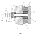
アノード接続ロッド120の好ましい実施の形態が、図2にさらに詳しく示されている。タイロッド120が、積層体の第1のアノード117へと溶接される一方で、他端にはねじ山が設けられ、アノード電気ケーブルを固定するように工夫された2枚のワッシャ131および2個のナット132を保持している。電気絶縁性の管状のブシュ119が、アノードの極性にあるロッド120と接地されたプレート107との間の接触を防止している。
A preferred embodiment of the
絶縁ブシュ125および平形ガスケット126が、このブシュ125およびガスケット126の外径に作用する高圧の空間を、ロッド120の周囲の低圧の空間から隔てている。2枚のガスケット126は、ブシュ125とプレート107aとの間およびブシュ125とアノード117との間でそれぞれ圧縮されている。ガスケット126を気密に保つため、ナット130が、タイロッド120、2枚のワッシャ128の間に位置する皿ばね129、および絶縁ブシュ127によってアノード117をプレート107aへと引き寄せている。プレート107aとアノード117との間の空間は、絶縁プレート118によって占められている。
An insulating
電気絶縁性のブシュ125および127を実現するための材料の選択は、どちらも大きな圧縮力に耐えなければならず、主としてブシュ125は、アノードの極性にある物品と接地との間に電気の分路を生じさせることがないよう、周囲の湿度を通してはならないため、特別な注意を必要とする。ブシュ125に使用することができる材料が、例えばガラス−マイカ複合材料である一方で、ブシュ127については、マイカ−紙の積層材料が適切かもしれない。
The choice of material to achieve the electrically insulating
図1に戻ると、圧力容器115の内側かつセル積層体101の外側の空間を加圧するためのポート123が、固定のヘッド107に設けられている。あるいは、この接続部は、外殻115の任意の場所に位置してもよい。
Returning to FIG. 1, a
積層体のセルフレームの互いのシールが、EP 0212240に開示されているようにOリングガスケットによって得られる本発明の好ましい実施の形態においては、容器115の内部の圧力が、積層体101の内部の動作圧力に比例しなければならない。
In a preferred embodiment of the invention where the seals of the cell frames of the laminate are obtained by O-ring gaskets as disclosed in EP 0212240, the pressure inside the
加圧媒体は、本発明の一態様によれば、好ましくはガスである。加圧ガスは、例えば、いずれも電気分解のプロセスとは無関係なチッ素、アルゴン、または二酸化炭素であってよい。瓶など、そのような不活性ガスのうちの1つの供給源を、減圧部または圧力コントローラが設けられた管による接続によって、ポート123へと接続することができる。第2の実施例においては、電解槽のジャケットを加圧するガスが、水の電気分解の場合の水素および酸素など、電気分解のプロセスによってもたらされる気体生成物であってよい。
The pressurized medium is preferably a gas according to one aspect of the present invention. The pressurized gas can be, for example, nitrogen, argon, or carbon dioxide, all independent of the electrolysis process. A source of one such inert gas, such as a bottle, can be connected to the
図3は、実質的に図1および2のように実現されたガス加圧式の電解槽200を備えている水の電気分解のための設備の例である。
FIG. 3 is an example of equipment for electrolysis of water including a gas pressurization type
電解槽200が、圧力容器220の内部にセル積層体210を備えており、水素および酸素を生成する。これらの水素および酸素が、セル積層体の固定のヘッドから配管201および202によって容器V−1およびV−2へとそれぞれもたらされる。これらのガスに、いくらかの電解質も混入しており、前記容器V−1およびV−2は、混入した液体からガスを分離し、液体を配管203および204によって電解槽へと戻さなければならない。
The
水素は、配管205を通って容器V−1から出るが、配管205において、圧力コントローラPC−1がバルブPCV−1を絞ることによって容器の内部の水素側の圧力を設定した後で、水素が配管207によって最終的な用途へと届けられる。
Hydrogen exits the container V-1 through the
酸素は、配管206を通って容器V−2から出て、配管209によって最終的な用途へと届けられる。容器V−2の内部の酸素側の圧力は、水素側の圧力の範囲内にあるようにバルブPDCVを絞る差圧コントローラPDCによって制御される。
Oxygen exits vessel V-2 through
配管206を圧力容器200へと接続している配管208が、容器そのものの内圧を、バルブPCV−02を絞ることによって器具PC−2によって制御される値に保つ。
A
上述の実施の形態を逆にし、2つのガスの役割を入れ換え、水素を容器220の加圧手段として使用することができる。
By reversing the above-described embodiment, the roles of the two gases are interchanged, and hydrogen can be used as the pressurizing means of the
電気分解プロセスの別の制御基準に対応するさらなる実施例が、図4に示されている。容器V−1およびV−2が、これら2つの容器の内圧を等しくし、したがってセルのカソードおよびアノード室の内圧を等しくするように、下部において配管によって互いに接続されている。この場合において、水素の送出圧力は、先の図3の場合のとおりに制御される。酸素の送出は、V−2の内部の電解質のレベルを一定に保つことによって制御される。容器220の加圧は、ループPC−2/PCV−2を介して水素そのものによって行なわれるものとして示されているが、図3の場合のように酸素によって行うことも可能である。当業者であれば、別の制御基準を選択することも可能であろう。
A further embodiment corresponding to another control criterion of the electrolysis process is shown in FIG. Vessels V-1 and V-2 are connected to each other by piping at the bottom so that the internal pressures of these two vessels are equal and therefore the internal pressures of the cell cathode and anode chambers are equal. In this case, the hydrogen delivery pressure is controlled as in FIG. Oxygen delivery is controlled by keeping the electrolyte level inside V-2 constant. Although the pressurization of the
本発明は、上述した目標および目的を達成し、水の電気分解からの高圧水素の生成に特に適している。 The present invention achieves the above goals and objectives and is particularly suitable for the production of high pressure hydrogen from the electrolysis of water.
Claims (15)
前記圧力容器の内部に位置し、複数のバイポーラ電気分解セルを第1の終端プレート(107a)および第2の終端プレート(108a)の間に積層して備えており、内圧のもとで動作するように構成されている電気分解セル積層体(101)、ならびに
前記セル積層体へと電解質を供給するための流体接続部、前記セル積層体から電気分解の生成物を集めるための流体接続部、および少なくともアノードおよびカソード接続部を含む電気接続部
を備えている電解槽(100)であって、
前記セル積層体の第1の終端プレート(107a)が、前記圧力容器の閉じた両端部のうちの一方に一体化し、前記セル積層体の固定のヘッド(107)を形成しており、
前記固定のヘッド(107)に、前記セル積層体との前記流体接続部(122)ならびにアノードおよびカソード電気接続部(120、121)が備えられ、
前記セル積層体の第2の終端プレート(108a)が、前記圧力容器(115)の内部に位置し、熱膨張または熱収縮に応答して前記第1の終端プレートおよび前記容器に対して長手方向に自由に移動でき、すなわち前記セル積層体の浮動のヘッド(108)を形成している
ことを特徴とする電解槽。 A pressure vessel (115) having an outer shell and closed ends;
A plurality of bipolar electrolysis cells are located inside the pressure vessel and are stacked between the first end plate (107a) and the second end plate (108a), and operate under an internal pressure. An electrolysis cell stack (101) configured as described above, a fluid connection for supplying electrolyte to the cell stack, a fluid connection for collecting products of electrolysis from the cell stack, And an electrolytic cell (100) comprising an electrical connection comprising at least an anode and a cathode connection,
A first end plate (107a) of the cell stack is integrated with one of the closed ends of the pressure vessel to form a fixed head (107) for the cell stack;
The fixed head (107) is provided with the fluid connection (122) to the cell stack and anode and cathode electrical connections (120, 121);
A second end plate (108a) of the cell stack is located within the pressure vessel (115) and is longitudinal with respect to the first end plate and the vessel in response to thermal expansion or contraction An electrolytic cell characterized in that it forms a floating head (108) of the cell stack.
前記セル積層体(101)の前記第1の終端プレート(107a)を貫通しており、該プレートから絶縁されており、前記積層体の第1のセルへと電気的に接続されている少なくとも第1の電気コネクタ(120)と、
前記第1の終端プレートに組み合わせられ、該プレートに電気的に接続されている少なくとも第2の電気コネクタ(121)と
を含んでおり、
前記第1の終端プレート(107a)が、前記積層体(101)の前記第2の終端プレート(108)に電気的に接続されている請求項1または2に記載の電解槽。 The electrical connection portion is
Passes through the first end plate (107a) of the cell stack (101), is insulated from the plate, and is electrically connected to the first cell of the stack. 1 electrical connector (120);
And at least a second electrical connector (121) coupled to and electrically connected to the first termination plate;
The electrolytic cell according to claim 1 or 2, wherein the first end plate (107a) is electrically connected to the second end plate (108) of the laminate (101).
絶縁プレート(118)が、前記第1のアノード(117)と前記固定のヘッド(107)との間に設けられ、絶縁ブシュ(125)およびガスケット(126)が、前記タイロッドを前記セル積層体の内部の圧力空間から隔てるために設けられている請求項6に記載の電解槽。 The first electrical connector (120) is a tie rod that passes through the fixed head (107) of the cell stack (101) and is insulated from the fixed head by a tubular bush (119). The tie rod (120) is attached to the first anode (117) of the laminate (101);
An insulating plate (118) is provided between the first anode (117) and the fixed head (107), and an insulating bush (125) and a gasket (126) connect the tie rod to the cell stack. The electrolytic cell according to claim 6, which is provided to be separated from an internal pressure space.
前記容器が、前記セル積層体の動作の最中に、ガスによって加圧されることを特徴とする電解槽。 A pressure vessel and an electrolysis cell stack inside the pressure vessel, the cell stack comprising a plurality of bipolar electrolysis cells stacked between first and second end plates. An electrolyzer for the electrolysis of water, in particular configured to operate under internal pressure,
The electrolytic cell, wherein the container is pressurized with a gas during the operation of the cell stack.
前記ガス生成物を受け取り、該ガス生成物を混入している電解質から分離するように構成された少なくとも1つの容器(V−1)、および
前記ガス生成物の少なくとも一部を加圧媒体として前記圧力容器(220)へと供給する流通配管(208)
を備える電気分解のための設備。 12. A cell stack (210) inside a pressure vessel (220), the cell stack being configured to provide at least a gas product under pressure. The electrolytic cell (200) according to one item,
At least one container (V-1) configured to receive the gas product and separate it from the electrolyte in which the gas product is mixed, and at least a portion of the gas product as a pressurized medium Distribution piping (208) for supply to pressure vessel (220)
Equipment for electrolysis comprising.
前記電解槽(200)において生成された水素を受け取る容器(V−1)および前記電解槽(200)において生成された酸素を受け取る別の容器(V−2)を少なくとも備えており、該容器が、それぞれ前記水素および酸素を混入している電解質から分離するように構成されており、
少なくとも前記水素の一部または前記酸素の一部を加圧媒体として前記それぞれの容器から前記圧力容器(220)へと供給する流通配管(208)を備えている
水の電気分解のための請求項12に記載の設備。 The cell stack (210) is configured to provide hydrogen and oxygen under pressure;
At least a container (V-1) for receiving hydrogen generated in the electrolytic cell (200) and another container (V-2) for receiving oxygen generated in the electrolytic cell (200), , Each configured to be separated from the electrolyte mixed with the hydrogen and oxygen,
The claim for electrolysis of water comprising a flow pipe (208) for supplying at least a part of the hydrogen or a part of the oxygen from the respective container to the pressure container (220) as a pressurized medium. 12. Equipment according to 12.
Applications Claiming Priority (3)
| Application Number | Priority Date | Filing Date | Title |
|---|---|---|---|
| EP08018734.7 | 2008-10-27 | ||
| EP08018734A EP2180087A1 (en) | 2008-10-27 | 2008-10-27 | High pressure electrolyser |
| PCT/EP2009/062066 WO2010049214A1 (en) | 2008-10-27 | 2009-09-17 | High pressure electrolyser |
Publications (3)
| Publication Number | Publication Date |
|---|---|
| JP2012506946A true JP2012506946A (en) | 2012-03-22 |
| JP2012506946A5 JP2012506946A5 (en) | 2012-08-30 |
| JP5524227B2 JP5524227B2 (en) | 2014-06-18 |
Family
ID=40433733
Family Applications (1)
| Application Number | Title | Priority Date | Filing Date |
|---|---|---|---|
| JP2011532557A Active JP5524227B2 (en) | 2008-10-27 | 2009-09-17 | High pressure electrolytic cell |
Country Status (10)
| Country | Link |
|---|---|
| US (1) | US8623195B2 (en) |
| EP (2) | EP2180087A1 (en) |
| JP (1) | JP5524227B2 (en) |
| CN (1) | CN102317505B (en) |
| CA (1) | CA2739019C (en) |
| DK (1) | DK2340322T3 (en) |
| ES (1) | ES2420982T3 (en) |
| PT (1) | PT2340322E (en) |
| RU (1) | RU2496918C2 (en) |
| WO (1) | WO2010049214A1 (en) |
Cited By (2)
| Publication number | Priority date | Publication date | Assignee | Title |
|---|---|---|---|---|
| JP2019218624A (en) * | 2018-06-14 | 2019-12-26 | パナソニックIpマネジメント株式会社 | Electrochemical type hydrogen pump |
| JP2021030162A (en) * | 2019-08-26 | 2021-03-01 | 株式会社日本トリム | Electrolysis unit |
Families Citing this family (19)
| Publication number | Priority date | Publication date | Assignee | Title |
|---|---|---|---|---|
| US20130140171A1 (en) * | 2008-07-15 | 2013-06-06 | Next Hydrogen Corporation | Electrolyser module |
| FR2957361B1 (en) * | 2010-03-12 | 2012-04-20 | Commissariat Energie Atomique | HIGH TEMPERATURE (EHT) ELECTROLYSIS WITH ENHANCED OPERATING SAFETY |
| EP2589426B1 (en) | 2011-11-02 | 2016-06-08 | Casale Sa | Method for removing nitrogen oxides from combustion fumes with on-site generation of ammonia |
| EP2617874B1 (en) * | 2012-01-18 | 2015-06-03 | H-TEC Systems GmbH | Electrolyser |
| CN104120441A (en) * | 2014-07-11 | 2014-10-29 | 包秀敏 | A double-membrane gas balancing device for hydrogen production by hydrolyzation |
| CN104911626B (en) * | 2015-06-23 | 2017-09-05 | 陕西华秦新能源科技有限责任公司 | A kind of high pressure water electrolysis hydrogen producing electrolytic cell |
| CN105780044A (en) * | 2016-04-21 | 2016-07-20 | 李兵 | Hydrogen-oxygen generator resisting high pressure and preventing corrosion |
| CN106119886B (en) * | 2016-06-23 | 2019-02-05 | 中国科学院过程工程研究所 | A method of pressurization electrolytic cell and intensified electrolysis |
| DE102016007739A1 (en) * | 2016-06-27 | 2017-12-28 | Westfälische Hochschule Gelsenkirchen Bocholt Recklinghausen | Device for energy conversion, in particular fuel cell or electrolyzer |
| CN106801232A (en) * | 2017-03-24 | 2017-06-06 | 陕西华秦新能源科技有限责任公司 | A kind of water electrolysis hydrogen producing electrolysis unit and its method |
| RU174582U1 (en) * | 2017-03-29 | 2017-10-23 | Федеральное государственное бюджетное учреждение "Национальный исследовательский центр "Курчатовский институт" | HIGH PRESSURE ELECTROLYZER |
| FR3087953B1 (en) * | 2018-10-26 | 2021-07-02 | Commissariat Energie Atomique | ELECTROCHEMICAL DEVICE INCLUDING AN ELECTROCHEMICAL ASSEMBLY PROVIDED IN A CONTAINMENT ENCLOSURE |
| US20220118406A1 (en) * | 2019-02-05 | 2022-04-21 | Arizona Board Of Regents On Behalf Of Arizona State University | System and method for production of synthetic fuel through co2 capture and water splitting |
| CN212511604U (en) * | 2020-06-22 | 2021-02-09 | 江门市恒通高科有限公司 | Humidifier with electrolytic sterilization module |
| JP7398109B2 (en) * | 2020-09-01 | 2023-12-14 | 守英 天白 | Electrode unit of water splitting gas generator |
| DK181191B1 (en) * | 2021-01-22 | 2023-04-13 | Stiesdal Hydrogen As | An electrolysis system comprising a buffer tank |
| DK180996B1 (en) * | 2021-02-10 | 2022-09-12 | Stiesdal Hydrogen As | Hydrogen production plant and method of its operation |
| RU2771380C1 (en) * | 2021-09-05 | 2022-05-04 | Сергей Станиславович Беднаржевский | Carbon dioxide utilization device |
| WO2024088889A2 (en) | 2022-10-25 | 2024-05-02 | Hitachi Zosen Inova Ag | Pressure electrolyser, electrolysis system and electrolysis method |
Citations (5)
| Publication number | Priority date | Publication date | Assignee | Title |
|---|---|---|---|---|
| JPH08239789A (en) * | 1995-03-01 | 1996-09-17 | Shinko Pantec Co Ltd | Hydrogen and oxygen generator |
| JPH09176884A (en) * | 1995-12-27 | 1997-07-08 | Shinko Pantec Co Ltd | Hydrogen and oxygen generator |
| JP2001131787A (en) * | 1999-10-29 | 2001-05-15 | Shinko Pantec Co Ltd | Pressure compensation structure of electrolysis cell |
| JP2006131935A (en) * | 2004-11-04 | 2006-05-25 | Hitachi Zosen Corp | Water electrolysis cell enclosed in container in water-electrolysis hydrogen-generating apparatus |
| JP2006307262A (en) * | 2005-04-27 | 2006-11-09 | Hitachi Zosen Corp | Device for absorbing size variation for container housing water electrolyzer |
Family Cites Families (12)
| Publication number | Priority date | Publication date | Assignee | Title |
|---|---|---|---|---|
| SU404062A1 (en) * | 1971-08-17 | 1973-10-26 | Ордена Трудового Красного Знамени Институт горного дела А. А. Скочинского | DEVICE FOR REGULATING GAS PRESSURE |
| SU487019A1 (en) * | 1973-10-02 | 1975-10-05 | Институт проблем материаловедения АН УССР | Electrolyzer for producing filterpress oxygen and hydrogen |
| CH672142A5 (en) | 1985-07-17 | 1989-10-31 | Metkon Sa | |
| AU4961293A (en) * | 1992-08-31 | 1994-03-29 | Neste Oy | Procedure for controlling pressure in electrolysis apparatus and electrolysis apparatus for producing hydrogen and oxygen |
| DE4418999C2 (en) | 1994-05-31 | 1996-04-11 | Von Hoerner System Gmbh | Pressure electrolyser with an encapsulated cell block made up of individual electrolysis cells |
| TW347417B (en) * | 1996-05-08 | 1998-12-11 | Shinkohan Gigyutsu Kk | An apparatus for producing hydrogen and oxygen |
| DE29622000U1 (en) | 1996-12-19 | 1997-02-13 | Mtu Friedrichshafen Gmbh | Pressurized water-encapsulated electrolyser |
| JP2000113995A (en) * | 1998-02-25 | 2000-04-21 | Mitsubishi Electric Corp | Lighting control device for discharge lamp, and h bridge circuit used for the device |
| DE10150557C2 (en) * | 2001-10-15 | 2003-12-18 | Mtu Friedrichshafen Gmbh | Pressure electrolyzer and method for operating such |
| KR20040080332A (en) * | 2002-01-29 | 2004-09-18 | 미쓰비시 쇼지 가부시키가이샤 | High-pressure hydrogen producing apparatus and producing method |
| DE10258525A1 (en) * | 2002-12-14 | 2004-07-01 | GHW Gesellschaft für Hochleistungselektrolyseure zur Wasserstofferzeugung mbH | Pressure electrolyzer and method for switching off a pressure electrolyzer |
| DE102005011316B4 (en) * | 2005-03-11 | 2006-12-14 | Kaufmann, Hans, Dipl.-Ing. (FH) | Electrolyzer and method for operating the electrolyzer |
-
2008
- 2008-10-27 EP EP08018734A patent/EP2180087A1/en not_active Withdrawn
-
2009
- 2009-09-17 DK DK09783130.9T patent/DK2340322T3/en active
- 2009-09-17 CA CA2739019A patent/CA2739019C/en active Active
- 2009-09-17 RU RU2011120974/04A patent/RU2496918C2/en active
- 2009-09-17 EP EP09783130.9A patent/EP2340322B1/en active Active
- 2009-09-17 ES ES09783130T patent/ES2420982T3/en active Active
- 2009-09-17 PT PT97831309T patent/PT2340322E/en unknown
- 2009-09-17 JP JP2011532557A patent/JP5524227B2/en active Active
- 2009-09-17 CN CN200980142704.XA patent/CN102317505B/en active Active
- 2009-09-17 US US13/125,123 patent/US8623195B2/en active Active
- 2009-09-17 WO PCT/EP2009/062066 patent/WO2010049214A1/en active Application Filing
Patent Citations (5)
| Publication number | Priority date | Publication date | Assignee | Title |
|---|---|---|---|---|
| JPH08239789A (en) * | 1995-03-01 | 1996-09-17 | Shinko Pantec Co Ltd | Hydrogen and oxygen generator |
| JPH09176884A (en) * | 1995-12-27 | 1997-07-08 | Shinko Pantec Co Ltd | Hydrogen and oxygen generator |
| JP2001131787A (en) * | 1999-10-29 | 2001-05-15 | Shinko Pantec Co Ltd | Pressure compensation structure of electrolysis cell |
| JP2006131935A (en) * | 2004-11-04 | 2006-05-25 | Hitachi Zosen Corp | Water electrolysis cell enclosed in container in water-electrolysis hydrogen-generating apparatus |
| JP2006307262A (en) * | 2005-04-27 | 2006-11-09 | Hitachi Zosen Corp | Device for absorbing size variation for container housing water electrolyzer |
Cited By (4)
| Publication number | Priority date | Publication date | Assignee | Title |
|---|---|---|---|---|
| JP2019218624A (en) * | 2018-06-14 | 2019-12-26 | パナソニックIpマネジメント株式会社 | Electrochemical type hydrogen pump |
| JP7249588B2 (en) | 2018-06-14 | 2023-03-31 | パナソニックIpマネジメント株式会社 | electrochemical hydrogen pump |
| JP2021030162A (en) * | 2019-08-26 | 2021-03-01 | 株式会社日本トリム | Electrolysis unit |
| WO2021039247A1 (en) * | 2019-08-26 | 2021-03-04 | 株式会社日本トリム | Electrolysis unit |
Also Published As
| Publication number | Publication date |
|---|---|
| RU2496918C2 (en) | 2013-10-27 |
| CN102317505B (en) | 2014-05-28 |
| WO2010049214A1 (en) | 2010-05-06 |
| EP2340322B1 (en) | 2013-04-10 |
| JP5524227B2 (en) | 2014-06-18 |
| CA2739019C (en) | 2017-10-10 |
| CN102317505A (en) | 2012-01-11 |
| ES2420982T3 (en) | 2013-08-28 |
| PT2340322E (en) | 2013-07-15 |
| DK2340322T3 (en) | 2013-07-08 |
| US8623195B2 (en) | 2014-01-07 |
| EP2180087A1 (en) | 2010-04-28 |
| US20110210012A1 (en) | 2011-09-01 |
| RU2011120974A (en) | 2012-12-10 |
| EP2340322A1 (en) | 2011-07-06 |
| CA2739019A1 (en) | 2010-05-06 |
Similar Documents
| Publication | Publication Date | Title |
|---|---|---|
| JP5524227B2 (en) | High pressure electrolytic cell | |
| JP6851378B2 (en) | Stand-alone system for tightening high temperature SOEC / SOFC stacks | |
| CN1751139B (en) | Electrolyzer apparatus and method for hydrogen production | |
| US7846307B2 (en) | High-pressure hydrogen production apparatus | |
| US7226529B2 (en) | Electrolyzer system to produce gas at high pressure | |
| US11108061B2 (en) | Water electrolysis or co-electrolysis reactor (SOEC) or fuel cell (SOFC) for pressurized operation and with a clamping system suitable for such operation | |
| KR102277912B1 (en) | Apparatus for producing high pressure hydrogen and oxygen gas by water electrolysis | |
| CN101818357A (en) | Electrochemical appliance | |
| US20110266142A1 (en) | Unitized electrolyzer apparatus | |
| US20120125779A1 (en) | Method and device for generating hydrogen and oxygen | |
| DK178317B1 (en) | Electrolyser Stack Divided into Sub-stacks | |
| JP2009541968A (en) | Fuel supply system for fuel cell | |
| EP4013907A1 (en) | High-pressure electrolysis device | |
| NL2023212B1 (en) | High-pressure electrolysis device | |
| US20210376339A1 (en) | Electrochemical hydrogen pump | |
| DK201400505A1 (en) | Pressurised Electrolysis Stack | |
| JP3733463B2 (en) | Hydrogen supply device using solid polymer water electrolyzer | |
| JP2013036068A (en) | High-pressure water electrolytic system and method for operating the same | |
| JP2006299390A (en) | Vessel storage water electrolytic tank in water electrolytic hydrogen generator | |
| NL2029726B1 (en) | Improvements in or relating to high-pressure electrolysis device | |
| JP4674659B2 (en) | Container-contained water electrolyzer for water electrolysis hydrogen generator | |
| KR100498234B1 (en) | Electrolytic Hydrogen-Oxygen generator | |
| CN117210836A (en) | High-pressure hydrogen electrolysis device and application method thereof | |
| DE102007051230A1 (en) | High pressure electrolysis apparatus producing hydrogen and oxygen from e.g. solar energy for storage, includes ultrasonic generators operating at different frequencies | |
| RU1828879C (en) | Electrolytic installation for water dissociation |
Legal Events
| Date | Code | Title | Description |
|---|---|---|---|
| A521 | Request for written amendment filed |
Free format text: JAPANESE INTERMEDIATE CODE: A523 Effective date: 20120713 |
|
| A621 | Written request for application examination |
Free format text: JAPANESE INTERMEDIATE CODE: A621 Effective date: 20120713 |
|
| A977 | Report on retrieval |
Free format text: JAPANESE INTERMEDIATE CODE: A971007 Effective date: 20130909 |
|
| A131 | Notification of reasons for refusal |
Free format text: JAPANESE INTERMEDIATE CODE: A131 Effective date: 20130917 |
|
| A521 | Request for written amendment filed |
Free format text: JAPANESE INTERMEDIATE CODE: A523 Effective date: 20131216 |
|
| A131 | Notification of reasons for refusal |
Free format text: JAPANESE INTERMEDIATE CODE: A131 Effective date: 20140204 |
|
| A521 | Request for written amendment filed |
Free format text: JAPANESE INTERMEDIATE CODE: A523 Effective date: 20140221 |
|
| TRDD | Decision of grant or rejection written | ||
| A01 | Written decision to grant a patent or to grant a registration (utility model) |
Free format text: JAPANESE INTERMEDIATE CODE: A01 Effective date: 20140318 |
|
| A61 | First payment of annual fees (during grant procedure) |
Free format text: JAPANESE INTERMEDIATE CODE: A61 Effective date: 20140409 |
|
| R150 | Certificate of patent or registration of utility model |
Ref document number: 5524227 Country of ref document: JP Free format text: JAPANESE INTERMEDIATE CODE: R150 |
|
| S111 | Request for change of ownership or part of ownership |
Free format text: JAPANESE INTERMEDIATE CODE: R313111 |
|
| R350 | Written notification of registration of transfer |
Free format text: JAPANESE INTERMEDIATE CODE: R350 |
|
| R371 | Transfer withdrawn |
Free format text: JAPANESE INTERMEDIATE CODE: R371 |
|
| S111 | Request for change of ownership or part of ownership |
Free format text: JAPANESE INTERMEDIATE CODE: R313111 |
|
| R350 | Written notification of registration of transfer |
Free format text: JAPANESE INTERMEDIATE CODE: R350 |
|
| R250 | Receipt of annual fees |
Free format text: JAPANESE INTERMEDIATE CODE: R250 |
|
| R250 | Receipt of annual fees |
Free format text: JAPANESE INTERMEDIATE CODE: R250 |
|
| R250 | Receipt of annual fees |
Free format text: JAPANESE INTERMEDIATE CODE: R250 |
|
| R250 | Receipt of annual fees |
Free format text: JAPANESE INTERMEDIATE CODE: R250 |
|
| R250 | Receipt of annual fees |
Free format text: JAPANESE INTERMEDIATE CODE: R250 |
|
| R250 | Receipt of annual fees |
Free format text: JAPANESE INTERMEDIATE CODE: R250 |
|
| R250 | Receipt of annual fees |
Free format text: JAPANESE INTERMEDIATE CODE: R250 |
|
| R250 | Receipt of annual fees |
Free format text: JAPANESE INTERMEDIATE CODE: R250 |