JP2012504061A - Media feed calibration - Google Patents
Media feed calibration Download PDFInfo
- Publication number
- JP2012504061A JP2012504061A JP2011529027A JP2011529027A JP2012504061A JP 2012504061 A JP2012504061 A JP 2012504061A JP 2011529027 A JP2011529027 A JP 2011529027A JP 2011529027 A JP2011529027 A JP 2011529027A JP 2012504061 A JP2012504061 A JP 2012504061A
- Authority
- JP
- Japan
- Prior art keywords
- media
- calibration target
- feed
- medium
- media feed
- Prior art date
- Legal status (The legal status is an assumption and is not a legal conclusion. Google has not performed a legal analysis and makes no representation as to the accuracy of the status listed.)
- Pending
Links
- 238000000034 method Methods 0.000 claims abstract description 68
- 230000003287 optical effect Effects 0.000 claims description 24
- 238000002955 isolation Methods 0.000 claims description 11
- 239000003550 marker Substances 0.000 claims description 10
- 230000005484 gravity Effects 0.000 claims description 9
- 230000000737 periodic effect Effects 0.000 claims description 9
- 230000007423 decrease Effects 0.000 claims description 5
- 230000003247 decreasing effect Effects 0.000 claims description 5
- 239000002131 composite material Substances 0.000 description 35
- 238000003491 array Methods 0.000 description 8
- 238000012937 correction Methods 0.000 description 7
- 239000012530 fluid Substances 0.000 description 7
- 238000012360 testing method Methods 0.000 description 5
- 238000004891 communication Methods 0.000 description 4
- 238000012545 processing Methods 0.000 description 4
- 239000000758 substrate Substances 0.000 description 4
- 230000015572 biosynthetic process Effects 0.000 description 3
- 230000007246 mechanism Effects 0.000 description 3
- 238000010586 diagram Methods 0.000 description 2
- 238000006073 displacement reaction Methods 0.000 description 2
- 239000008393 encapsulating agent Substances 0.000 description 2
- 238000010438 heat treatment Methods 0.000 description 2
- 239000007788 liquid Substances 0.000 description 2
- 238000012423 maintenance Methods 0.000 description 2
- 238000004519 manufacturing process Methods 0.000 description 2
- 230000001681 protective effect Effects 0.000 description 2
- 238000002310 reflectometry Methods 0.000 description 2
- 238000012935 Averaging Methods 0.000 description 1
- 239000011248 coating agent Substances 0.000 description 1
- 238000000576 coating method Methods 0.000 description 1
- 239000003086 colorant Substances 0.000 description 1
- 230000000295 complement effect Effects 0.000 description 1
- 230000008021 deposition Effects 0.000 description 1
- 238000013461 design Methods 0.000 description 1
- 230000000694 effects Effects 0.000 description 1
- 238000011049 filling Methods 0.000 description 1
- 238000010304 firing Methods 0.000 description 1
- 238000009432 framing Methods 0.000 description 1
- 238000007689 inspection Methods 0.000 description 1
- 238000011068 loading method Methods 0.000 description 1
- 230000000873 masking effect Effects 0.000 description 1
- 238000005259 measurement Methods 0.000 description 1
- 238000000926 separation method Methods 0.000 description 1
- 238000003786 synthesis reaction Methods 0.000 description 1
- 230000009897 systematic effect Effects 0.000 description 1
Images


Classifications
-
- B—PERFORMING OPERATIONS; TRANSPORTING
- B41—PRINTING; LINING MACHINES; TYPEWRITERS; STAMPS
- B41J—TYPEWRITERS; SELECTIVE PRINTING MECHANISMS, i.e. MECHANISMS PRINTING OTHERWISE THAN FROM A FORME; CORRECTION OF TYPOGRAPHICAL ERRORS
- B41J11/00—Devices or arrangements of selective printing mechanisms, e.g. ink-jet printers or thermal printers, for supporting or handling copy material in sheet or web form
- B41J11/36—Blanking or long feeds; Feeding to a particular line, e.g. by rotation of platen or feed roller
- B41J11/42—Controlling printing material conveyance for accurate alignment of the printing material with the printhead; Print registering
-
- B—PERFORMING OPERATIONS; TRANSPORTING
- B41—PRINTING; LINING MACHINES; TYPEWRITERS; STAMPS
- B41J—TYPEWRITERS; SELECTIVE PRINTING MECHANISMS, i.e. MECHANISMS PRINTING OTHERWISE THAN FROM A FORME; CORRECTION OF TYPOGRAPHICAL ERRORS
- B41J2/00—Typewriters or selective printing mechanisms characterised by the printing or marking process for which they are designed
- B41J2/005—Typewriters or selective printing mechanisms characterised by the printing or marking process for which they are designed characterised by bringing liquid or particles selectively into contact with a printing material
- B41J2/01—Ink jet
- B41J2/21—Ink jet for multi-colour printing
- B41J2/2132—Print quality control characterised by dot disposition, e.g. for reducing white stripes or banding
-
- B—PERFORMING OPERATIONS; TRANSPORTING
- B41—PRINTING; LINING MACHINES; TYPEWRITERS; STAMPS
- B41J—TYPEWRITERS; SELECTIVE PRINTING MECHANISMS, i.e. MECHANISMS PRINTING OTHERWISE THAN FROM A FORME; CORRECTION OF TYPOGRAPHICAL ERRORS
- B41J29/00—Details of, or accessories for, typewriters or selective printing mechanisms not otherwise provided for
- B41J29/02—Framework
-
- B—PERFORMING OPERATIONS; TRANSPORTING
- B41—PRINTING; LINING MACHINES; TYPEWRITERS; STAMPS
- B41J—TYPEWRITERS; SELECTIVE PRINTING MECHANISMS, i.e. MECHANISMS PRINTING OTHERWISE THAN FROM A FORME; CORRECTION OF TYPOGRAPHICAL ERRORS
- B41J29/00—Details of, or accessories for, typewriters or selective printing mechanisms not otherwise provided for
- B41J29/38—Drives, motors, controls or automatic cut-off devices for the entire printing mechanism
- B41J29/393—Devices for controlling or analysing the entire machine ; Controlling or analysing mechanical parameters involving printing of test patterns
Abstract
本校正方法は、i.印刷媒体上にキャリブレーションターゲットを印刷するステップと、ii.印刷媒体を、媒体送り量だけ送るステップと、iii.印刷媒体上にキャリブレーションターゲットを印刷するステップと、iv.印刷媒体を、前回の媒体送り量にオフセット量を加算した分だけ送るステップと、v.ステップiiiとivを繰り返すステップと、媒体送りキャリブレーションターゲットの光反射を、媒体送りキャリブレーションターゲットに沿った位置に関して測定するステップと、媒体送りキャリブレーションターゲットに沿った、光反射が最大であった位置に対応する位置を特定するステップと、光反射が最大であった位置を、媒体送りキャリブレーションターゲットの所定の位置と比較して、プリンタ内の媒体送りを校正するステップと、を含む。This calibration method is i. Printing a calibration target on a print medium; ii. Sending the print medium by the media feed amount; iii. Printing a calibration target on a print medium; iv. Sending print media by the amount of offset added to the previous media feed amount; v. Repeating steps iii and iv, measuring the light reflection of the media feed calibration target with respect to a position along the media feed calibration target, and having the maximum light reflection along the media feed calibration target Determining a position corresponding to the position, and comparing the position where the light reflection was maximum with a predetermined position of the medium feed calibration target to calibrate the media feed in the printer.
Description
本発明は一般に、デジタル制御式印刷装置の分野、特にこれらの装置内の媒体送りの校正に関する。 The present invention relates generally to the field of digitally controlled printing devices, and more particularly to media feed calibration in these devices.
数多くの種類の印刷システムが1つまたは複数の印刷ヘッドを備えており、この印刷ヘッドに含まれるアレイ状のマーキング要素は、印刷媒体上の特定の位置に特定の大きさ、色等のマーキングを行って、所望の画像を印刷するように制御される。いくつかの種類の印刷システムでは、マーキング要素アレイが幅全体にわたり、画像は1度に1行ずつ印刷される。しかしながら、印刷の用途の種類によっては、ページ幅にわたるマーキング要素アレイを用いた印刷ヘッドはコストが高すぎるため、キャリッジを用いる印刷方式が採用される。 Many types of printing systems include one or more print heads, and the array of marking elements contained in the print heads mark specific sizes, colors, etc. at specific locations on the print media. Go and control to print the desired image. In some types of printing systems, the marking element array spans the entire width and the image is printed one line at a time. However, depending on the type of printing application, a print head using a marking element array that spans the page width is too expensive, so a printing method using a carriage is employed.
キャリッジ式印刷システム(卓上プリンタ、大規模プロッタその他、いずれのものかを問わない)においては、印刷ヘッド(複数の場合もある)はキャリッジに取り付けられ、キャリッジは記録媒体を通り越してキャリッジ走査方向に移動し、その間、マーキング要素がドットの帯であるスワス(swath)を印刷するように駆動される。スワスの端において、キャリッジが停止し、印刷が一時停止して、記録媒体が送られる。すると新たなスワスが印刷され、このようにして画像が1スワス分ずつ形成される。キャリッジ式プリンタにおいて、マーキング要素アレイは一般にアレイ方向に沿って配置され、これは媒体送り方向に略平行であり、キャリッジ走査方向に対して略垂直である。 In a carriage-type printing system (desktop printer, large-scale plotter, etc.), the print head (s) is attached to the carriage, and the carriage passes through the recording medium in the carriage scanning direction. In the meantime, the marking element is driven to print a swath, which is a band of dots. At the end of the swath, the carriage stops, printing temporarily stops, and the recording medium is fed. Then, a new swath is printed, and an image is formed for each swath in this way. In a carriage-type printer, the marking element array is generally arranged along the array direction, which is substantially parallel to the media feed direction and substantially perpendicular to the carriage scan direction.
記録媒体は、単票として供給されるか連続ロール媒体として供給されるかを問わず、一般にモータによって駆動されるローラ群によって送られる。ローラの角回転の量は、プリンタのコントローラによって制御される。角回転θは、ステップモータによる送りステップ(advance step)の数を特定することによって実現でき、および/またはθは、たとえば紙送りローラに同軸的に取り付けられたロータリエンコーダを使って監視できる。媒体が送られた距離は名目上Rθであり、Rはロータリエンコーダに同軸的に取り付けられた媒体送りローラの半径で、θは半径方向に測定される。しかしながら、この名目上の媒体送り距離には、さまざまな誤差要因がある。第一に、ローラの製造ばらつきまたは摩耗によって、ローラの半径が正確にRと等しい状態ではなくなることがある。第二に、用紙の印刷面の送り距離は実際には(R+t)θであり、tは送られる媒体の厚さである。そのため、媒体の厚さが送り距離に影響を与えうる。第三に、媒体とローラとの間で滑りが生じることがある。 Regardless of whether the recording medium is supplied as a single sheet or a continuous roll medium, the recording medium is generally fed by a roller group driven by a motor. The amount of angular rotation of the roller is controlled by the printer controller. The angular rotation θ can be realized by specifying the number of advance steps by the step motor, and / or θ can be monitored using a rotary encoder coaxially attached to the paper feed roller, for example. The distance that the media is fed is nominally Rθ, where R is the radius of the media feed roller mounted coaxially to the rotary encoder, and θ is measured in the radial direction. However, there are various error factors in this nominal media feed distance. First, due to roller manufacturing variations or wear, the roller radius may not be exactly equal to R. Second, the feeding distance of the printing surface of the paper is actually (R + t) θ, and t is the thickness of the medium to be fed. For this reason, the thickness of the medium can affect the feeding distance. Third, slippage may occur between the media and the roller.
媒体の送りが不足であると、媒体送り誤差によって、印刷されたデータの隣接するスワスが部分的に重複するために、画像に黒い筋が入ることがある。媒体の送りが過剰であると、媒体送り誤差によって、印刷されたデータの隣接するスワスの間にギャップがあるため、画像に白い筋が入ることがある。さらに、過剰送り(overfeeding)と過小送り(underfeeding)により、画像全体の長さが長すぎ、あるいは短すぎることになる。特に、長い画像の場合、媒体送り距離の比較的小さな系統的誤差であっても、像のフレーミングや連結(tiling)時の問題の原因となりうる。 If the feeding of the medium is insufficient, the adjacent swaths of the printed data partially overlap due to a medium feeding error, so that black streaks may appear in the image. If the media feed is excessive, the media feed error may cause white streaks in the image due to gaps between adjacent swaths of the printed data. Furthermore, overfeeding and underfeeding can cause the entire image to be too long or too short. In particular, in the case of a long image, even a relatively small systematic error in the media feed distance can cause problems during image framing and tilting.
媒体送り誤差を補正する様々な方法がこれまでに開示されてきた。特許文献1(米国特許第5,825,378号)は、一連の行を印刷する方法を開示しており、連続する行は媒体送りステップによって分離される、すると、行の間隔は、媒体シートを90度回転させ、キャリッジに取り付けられた光学センサを使って行間距離を測定することによって測定できる。実際の行間距離を名目行間距離と比較して、その誤差を使って、ある所望の時点での媒体送りにおいてローラが送られるべき角回転を補正する。この方法では、使用者が直接介入して媒体を回転させる必要がある。 Various methods for correcting media feed errors have been previously disclosed. U.S. Patent No. 5,825,378 discloses a method of printing a series of rows, where successive rows are separated by a media advance step, where the row spacing is the media sheet. , And the distance between the lines can be measured by using an optical sensor attached to the carriage. The actual line distance is compared to the nominal line distance and the error is used to correct the angular rotation that the roller should be fed in at the media feed at some desired time. This method requires the user to intervene directly to rotate the media.
特許文献2(米国特許第6,137,592号)は、媒体送りの数値を連続的に増減させて、テストパターンを印刷する方法を開示している。数値を増減させたら、使用者はそのテストパターンのうち、白または黒の筋の量が最も少ない領域を選択する。選択された媒体送りを、新規の名目送り距離としてメモリに記憶することができる。この方法では、使用者が介入してテストイメージの中で最も見た目の良い部分を選択することが必要であり、使用者による誤差が生じやすい。 Patent Document 2 (US Pat. No. 6,137,592) discloses a method of printing a test pattern by continuously increasing / decreasing a medium feeding value. When the numerical value is increased or decreased, the user selects an area having the smallest amount of white or black stripes in the test pattern. The selected media feed can be stored in memory as a new nominal feed distance. In this method, it is necessary for the user to intervene and select the most visually pleasing part of the test image, which is likely to cause an error by the user.
特許文献3(米国特許第7,210,758号)は、チェス盤模様等のオンオフパターンを含むテストパターンを印刷し、媒体送りの数値を増大させる方法を開示している。最適な媒体送りでは、1回目のパスによる黒いパターンを2回目のパスによる明るいパターンとぴったりと合い、パターンが、最適な媒体送りにとって最も暗い(光学濃度が最大)ものとなる。印刷されたパターンの検査は、パターンの光学濃度を測定し、最適な媒体送りの数値をテストパターンの中で光学濃度が最大の領域に対応するものとして特定することにより、自動的に行われる。 Patent Document 3 (US Pat. No. 7,210,758) discloses a method of printing a test pattern including an on / off pattern such as a chessboard pattern and increasing the numerical value of the medium feeding. Optimal media feed closely matches the black pattern from the first pass with the bright pattern from the second pass, and the pattern is the darkest (highest optical density) for optimal media feed. Inspection of the printed pattern is performed automatically by measuring the optical density of the pattern and identifying the optimum media feed value as corresponding to the region of maximum optical density in the test pattern.
上記の方法は、用途によっては十分であるが、画像品質の改良に対する顧客の期待は常に高まり続けているため、さらに精密で、測定誤差が発生しにくい媒体送りの校正方法が求められる。 Although the above method may be sufficient depending on the application, the customer's expectation for improving the image quality is constantly increasing. Therefore, there is a need for a more precise medium feed calibration method that is less prone to measurement errors.
本発明の1つの態様によれば、プリンタの媒体送りを校正する方法が提供され、プリンタは媒体送り方向に略平行な方向に沿って配置されたマーキング要素アレイを備え、この方法は、キャリブレーションターゲットの印刷設定を特定するマスクを提供するステップと、印刷媒体上に媒体送りキャリブレーションターゲットを、i.マーキング要素アレイを使って、印刷媒体上にキャリブレーションターゲットを印刷するステップ、ii.印刷媒体を、媒体送り量だけ送るステップ、iii.マーキング要素アレイを使って、印刷媒体上にキャリブレーションターゲットを印刷するステップ、iv.印刷媒体を、前回の媒体送り量にオフセット量を加算した分だけ送るステップ、v.ステップiiiとivを繰り返し、媒体送りキャリブレーションターゲットを完成させるステップによって印刷するステップと、媒体送りキャリブレーションターゲットの光反射を、媒体送りキャリブレーションターゲットに沿った位置に関して測定するステップと、媒体送りキャリブレーションターゲットに沿った、光反射が最大であった位置に対応する位置を特定するステップと、光反射が最大であった位置を、媒体送りキャリブレーションターゲットの所定の位置と比較して、プリンタ内の媒体送りを校正するステップと、を含む。 According to one aspect of the present invention, a method for calibrating a media feed of a printer is provided, the printer comprising an array of marking elements arranged along a direction substantially parallel to the media feed direction. Providing a mask specifying the print settings of the target; and a media advance calibration target on the print media; i. Printing a calibration target on a print medium using an array of marking elements; ii. Sending the print medium by the media feed amount, iii. Printing a calibration target on a print medium using an array of marking elements; iv. Sending print media by the amount of offset added to the previous media feed amount, v. Repeating steps iii and iv to complete the media advance calibration target, printing, measuring the light reflection of the media advance calibration target with respect to a position along the media advance calibration target, and media advance calibration Determining the position along the target corresponding to the position where the light reflection is maximum, and comparing the position where the light reflection is maximum with the predetermined position of the media feed calibration target. Calibrating the media feed of
本発明の別の態様によれば、上記の方法はまた、印刷媒体上に第二の媒体送りキャリブレーションターゲットを、i.マーキング要素アレイを使って、印刷媒体上にキャリブレーションターゲットを印刷するステップ、ii.印刷媒体を、媒体送り量だけ送るステップ、iii.マーキング要素アレイ使って、印刷媒体上にキャリブレーションターゲットを印刷するステップ、iv.印刷媒体を、前回の媒体送り量だけ送るステップ、v.ステップiiiとivを繰り返し、媒体送りキャリブレーションターゲットを完成させるステップによって印刷するステップと、第二の媒体送りキャリブレーションターゲットの光反射を、第二の媒体送りキャリブレーションターゲットに沿った位置に関して測定するステップと、角回転に関して光反射の周期的な変動を特定し、記憶するステップと、記憶された周期的変動およびローラの特定の角位置を示すマーカの位置に基づいて、媒体送りローラの回転を調整するステップと、を含んでいてもよい。 According to another aspect of the invention, the above method also includes a second media advance calibration target on the print media, i. Printing a calibration target on a print medium using an array of marking elements; ii. Sending the print medium by the media feed amount, iii. Printing a calibration target on a print medium using an array of marking elements; iv. Sending print media by the previous media feed amount, v. Steps iii and iv are repeated to print by completing the media advance calibration target, and the light reflection of the second media advance calibration target is measured with respect to a position along the second media advance calibration target. Identifying and storing periodic variations in light reflection with respect to angular rotation, and rotating the media feed roller based on the stored periodic variation and the position of the marker indicating the particular angular position of the roller. Adjusting. May be included.
本発明のまた別の態様によれば、プリンタにおける媒体送りを校正する方法が提供され、プリンタは媒体送りローラと、ローラの特定の角位置を示すマーカと、媒体送り方向に略平行な方向に沿って配置されたマーキング要素アレイを備え、この方法は、キャリブレーションターゲットの印刷設定を特定するマスクを提供するステップと、印刷媒体上に媒体送りキャリブレーションターゲットを、i.マーキング要素アレイを使って、印刷媒体上にキャリブレーションターゲットを印刷するステップ、ii.印刷媒体を、媒体送り量だけ送るステップ、iii.マーキング要素アレイを使って、印刷媒体上にキャリブレーションターゲットを印刷するステップ、iv.印刷媒体を、前回の媒体送り量だけ送るステップ、v.ステップiiiとivを繰り返し、媒体送りキャリブレーションターゲットを完成させるステップによって印刷するステップと、媒体送りキャリブレーションターゲットの光反射を、媒体送りキャリブレーションターゲットに沿った位置に関して測定するステップと、角回転に関して光反射の周期的な変動を特定し、記憶するステップと、記憶された周期的変動およびローラの特定の角位置を示すマーカの位置に基づいて、媒体送りローラの回転を調整するステップと、を含む。 According to yet another aspect of the invention, a method for calibrating media feed in a printer is provided, wherein the printer is in a direction substantially parallel to the media feed direction, a media feed roller, a marker indicating a particular angular position of the roller, and A marking element array disposed along the method, the method comprising: providing a mask identifying print settings of the calibration target; and media feeding calibration target on the print medium, i. Printing a calibration target on a print medium using an array of marking elements; ii. Sending the print medium by the media feed amount, iii. Printing a calibration target on a print medium using an array of marking elements; iv. Sending print media by the previous media feed amount, v. Repeat steps iii and iv to complete the media advance calibration target, printing, measuring the light reflection of the media advance calibration target with respect to the position along the media advance calibration target, and angular rotation Identifying and storing periodic fluctuations in light reflection; and adjusting rotation of the media feed roller based on the stored periodic fluctuations and the position of a marker indicating a particular angular position of the roller. Including.
以下の、本発明の好ましい実施形態の詳細な説明では、添付の図面を参照する。 In the following detailed description of preferred embodiments of the invention, reference is made to the accompanying drawings.
この説明は特に、本発明による装置の一部を形成する、またはそれとより直接的に協働する要素に関するものである。理解すべき点として、図または文で特に説明されていない要素は、当業者の間で周知の各種の形態をとることができる。 This description relates in particular to the elements that form part of the device according to the invention or cooperate more directly with it. It should be understood that elements not specifically described in the figures or text can take various forms well known to those skilled in the art.
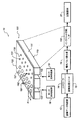
図1を参照すると、インクジェットプリンタシステム10の概略が示されており、これは米国特許第7,350,902号に記載されており、同特許の全文を引用によって本願に援用する。プリンタシステム10は、画像データの供給源12を備え、これはコントローラ14によって液滴吐出の命令として解釈されるデータ信号を供給する。コントローラ14は、印刷のために画像をレンダリングする画像処理ユニット15を備え、電気エネルギーパルスの発生源16に信号を出力し、このパルスはインクジェット印刷ヘッド100に入力され、印刷ヘッド100は少なくとも1つの印刷ヘッドダイ110を有する。
Referring to FIG. 1, an overview of an
図1に示される例において、インクジェット印刷ヘッド100のための2つのノズルアレイ120,130がある。第一のノズルアレイ120のノズル121は、第二のノズルアレイ130のノズル131より開口面積が大きい。この例において、2つのノズルアレイ120,130の各々は、2本の互い違いのノズルの列を有し、各列のノズル密度は1インチあたり600である。したがって、各アレイ120,130の有効ノズル密度は1インチあたり1200である。記録媒体上の画素に、用紙送り方向に沿って通し番号を付けたとすると、アレイの一方の列のノズルは奇数番号の画素を印刷し、そのアレイのもう一方の列のノズルは偶数番号の画素を印刷する。隣接する画素は、マーキング要素が互い違いに配置されたアレイ形状におけるアレイの異なる列のノズルによって印刷されるが、隣接するマーキング画素を生成するマーキング要素は、隣接するマーキング要素であると認められる。ノズルアレイの1番のノズルは、この例では3番のノズルと同じ行にあり、2番のノズル番号はもう一方の行にある。1番のノズルと3番のノズルの間の物理的距離は1/600インチである。2番のノズルと1番のノズルの間の中心間距離は、そのアレイの行の間の間隔により、1/600インチより大きいかもしれない。しかしながら、1番のノズルと2番のノズルの間のアレイ方向に沿った距離は、この例ではd=1/1200インチである。これに対応する、アレイ方向への画素の間隔も、この例では1/1200インチである。
In the example shown in FIG. 1, there are two
各ノズルアレイとは、対応するインク供給経路が流体連通している。インク供給経路122はノズルアレイ120と流体連通し、インク供給経路132はノズルアレイ130と流体連通する。流体供給経路122,132の一部が、図1において、印刷ヘッドダイ基板111の開口部として示されている。1つまたは複数の印刷ヘッドダイ110をインクジェット印刷ヘッド100に含めることができるが、図1では、説明をわかりやすくするための例として、印刷ヘッドダイ110が1つのみ示されている。印刷ヘッドダイは、支持部材の上に配置されており、これについては図2に関して後述する。図1において、第一のインク供給源18は、インク供給経路122を通じて第一のノズルアレイ120にインクを供給し、第二のインク供給源19は、インク供給経路132を通じて第二のノズルアレイ130にインクを供給する。異なるインク供給源18,19が示されているが、用途によっては、1つのインク供給源を設けて、それぞれインク供給経路122,132を通じて両方のノズル経路120,130にインクを供給することが有利かもしれない。また、ある実施形態では、印刷ヘッドダイ110に含まれるノズルアレイは2つより少なく、また別の実施形態では、3つ以上のノズルアレイが使用される。いくつかの実施形態において、印刷ヘッドダイ110のすべてのノズルは、1つの印刷ヘッドダイの上に複数のサイズのノズルを設けるのではなく、同じサイズであってもよい。
Each nozzle array is in fluid communication with a corresponding ink supply path. The
液滴形成機構(図1では示さず)がノズルと関連付けられる。液滴形成機構には各種のタイプがあり、インクの一部を蒸発させ、これによって液滴を吐出させる加熱要素を備えるものや、液体チャンバの容量を収縮させて吐出を起こさせる圧電トランスデューサを備えるものや、移動され(たとえば、二重層要素を加熱する等による)、それによって吐出を起こさせるアクチュエータを備えるものがある。いずれの場合も、パルス発生源16からの電気パルスは、所望の蒸着パターンに応じて、各種の液滴吐出器に送信される。図1の例において、ノズルアレイ120から吐出される小滴181は、ノズルアレイ130から吐出される小滴182より大きく、これはノズルの開口面積が大きいからである。一般に、それぞれノズルアレイ120,130に関連付けられる液滴形成機構(図示せず)の別の態様でも、サイズを違えて、大きさの異なる液滴の液滴吐出工程が最適化される。動作中、インク小滴は記録媒体20の上に堆積される。
A droplet formation mechanism (not shown in FIG. 1) is associated with the nozzle. There are various types of droplet formation mechanisms, including a heating element that evaporates part of the ink and thereby ejects the droplet, and a piezoelectric transducer that causes ejection by contracting the volume of the liquid chamber Some are equipped with actuators that are moved (eg, by heating a double layer element, etc.), thereby causing ejection. In any case, the electric pulse from the
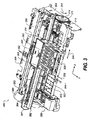
図2は、印刷ヘッド筐体250の一部の斜視図であり、これは例としてのインクジェット印刷ヘッド100である。印刷ヘッド筐体250は、3つの印刷ヘッドダイ251(印刷ヘッドダイ110と同様)を備え、各印刷ヘッドダイは2つのノズルアレイ253を有しているため、印刷ヘッド筐体250には合わせて6つのノズルアレイ253がある。この例の6つのノズルアレイ253は、それぞれ別のインク供給源(図2には示さず)、たとえばシアン、マゼンタ、イエロー、テキストブラック(text black)、フォトブラック、および無色の保護印刷流体等に連結されていてもよい。6つのノズルアレイ253の各々は方向254に沿って配置されていてもよく、方向254に沿った各ノズルアレイの長さLは一般に、1インチまたはそれより以下の程度である。記録媒体の一般的な長さは、写真プリントの場合は6インチ(4インチ×6インチ)、または8.5×11インチ用紙の場合は11インチであり、ロール紙用プリンタは、100フィートまたはそれ以上の長い媒体を使用することができる。したがって、画像全体を印刷するためには、印刷ヘッド筐体250が記録媒体を横切って移動する間に、多数のスワスが連続的に印刷される。1本のスワスが印刷されたら、記録媒体をノズルアレイ方向254に略平行な媒体送り方向304に沿って送られる。
FIG. 2 is a perspective view of a portion of the
シングルパス印刷モードは、アレイ内の各マーキング要素が、1本のスワスにおけるある画素の行の中の画素位置のすべてを印刷するために割り当てられる。シングルパス印刷モードは比較的高速であり、一般にドラフトモードで使用される。しかしながら、噴射に方向ずれやその他の異常があると、シングルパス印刷モードで印刷された画像には、好ましくない白または黒の筋ができる。したがって、より高品質の印刷モードでは、複数の重複するパスを使って画像を印刷する。マルチパス印刷の場合、印刷マスクを使って、ある画素の行の中のさまざまな印刷位置を印刷するために、異なるマーキング要素に責任を割り当てる。さらに、印刷パス間の媒体送り距離はマルチパス印刷のノズルアレイの長さより小さい。その代わりに、ノズルアレイの長さがLで、マルチパス印刷のパス数がmであると、所望の媒体送り距離は約L/mとなる。 Single pass printing mode is assigned for each marking element in the array to print all of the pixel locations in a row of pixels in a swath. Single pass printing mode is relatively fast and is generally used in draft mode. However, if there is a misorientation or other anomaly in the jet, the image printed in single pass printing mode will have undesirable white or black streaks. Therefore, in a higher quality print mode, an image is printed using a plurality of overlapping passes. In multi-pass printing, a print mask is used to assign responsibility to different marking elements to print various print positions within a row of pixels. Furthermore, the media feed distance between printing passes is smaller than the length of the nozzle array for multi-pass printing. Instead, if the length of the nozzle array is L and the number of passes of multi-pass printing is m, the desired medium feed distance is about L / m.
印刷ヘッドダイ251が、たとえばワイヤボンディングまたはTABボンディングによって電気的に相互接続されるフレキシブル回路257も図2に示されている。相互接続は、これを保護するために封入材256によって被覆される。フレキシブル回路257は、印刷ヘッド筐体250の側面から曲がり、コネクタ基板258に接続する。印刷ヘッド筐体250がキャリッジ200(図3参照)の中に取り付けられると、コネクタ基板258はキャリッジ200の上のコネクタ(図示せず)に電気的に接続され、電気信号が印刷ヘッドダイ251に送信されるようになる。
A
図3は、デスクトップ型キャリッジ式プリンタの一部を示す。プリンタのいくつかの部品は図3に描かず、他の部品がより明確に見えるようにした。プリンタ筐体300は、印刷領域303を有し、キャリッジ200はこれを横切って、プリンタ筐体300の右側306と左側307の間でX軸に沿ってキャリッジ走査方向305に前後に往復移動され、その間、キャリッジ200に取り付けられた印刷ヘッド筐体250の上の印刷ヘッドダイ251から液滴が吐出される。キャリッジモータ380は、ベルト384を移動させて、キャリッジ200をキャリッジガイドレール382に沿って移動させる。エンコーダセンサ(図示せず)がキャリッジ200に取り付けられ、エンコーダフェンス383に関するキャリッジの位置を示す。
FIG. 3 shows a part of a desktop carriage type printer. Some parts of the printer are not depicted in FIG. 3 so that other parts are more clearly visible. The
キャリッジ200には、図4に示されるように、光学センサ(キャリッジセンサともいう)210が取り付けられている。キャリッジセンサ210はLED等の発光手段を備え、これは光を記録媒体に照射する。記録媒体から反射された光は、これもキャリッジセンサ210に設けられた光センサによって受けられる。先行技術のキャリッジセンサ210の一般的な用途は、電子信号を供給することによって印刷ヘッドの位置合わせを評価することであり、電子信号が分析されて、印刷されたマークの位置が判断される。
As shown in FIG. 4, an optical sensor (also referred to as a carriage sensor) 210 is attached to the
印刷ヘッド筐体250はキャリッジ200に取り付けられ、インク供給源262,264は印刷ヘッド筐体250の中に取り付けられる。印刷ヘッド筐体250の取付方位は、図2の図に関して回転され、印刷ヘッドダイ251(図2に示す)が印刷ヘッド筐体250の底側に配置され、インクの小滴が下方に、図3の印刷領域303の記録媒体へと吐出されるようになっている。インク供給部262には、この例においてシアン、マゼンタ、イエロー、フォトブラック、無色の保護液という5つのインク供給源が含まれ、インク供給源264にはテキストブラック用のインク供給源が含まれる。紙または他の記録媒体(本明細書においては、紙、媒体または印刷媒体と総合的に呼ぶことがある)は、この例において、プリンタ筐体300の前部308で、用紙装填入口方向302に沿って装填される。
The
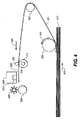
各種のローラを使って記録媒体がプリンタ内で送られ、これは、図4の側面図で概略的に示されている。この例において、ピックアップローラ320は、用紙またはその他の記録媒体のスタック370の1番上の用紙371を矢印302の方向に移動させる。方向転換ローラ322は図3のプリンタ筐体300の後部309に向かって、用紙をC字形経路(湾曲した後方壁面と協働する)に沿って移動させ、用紙は引き続き、図3に示されるプリンタの後部309から方向矢印304に沿って送られる。用紙は次に、送りローラ312とアイドラローラ(複数の場合もある)323によって移動され、図3のY軸に沿って、印刷領域303を通過して、そこから排紙ローラ324と星型車(star wheel)(325)へと搬送され、画像が印刷された用紙が方向304に沿って排出される。印刷領域303の付近で用紙は方向304に沿って搬送されるため、印刷に関して、方向304は媒体送り方向と呼ばれる。送りローラ312は、その軸に沿って紙送りローラシャフト319を有し、送りローラ歯車311が送りローラシャフト319に取り付けられる。送りローラ312は、送りローラシャフト319に取り付けられた別のローラまたは、送りローラシャフト319上に薄い高摩擦コーティングを有していてもよい。ロータリエンコーダ(図示せず)をシャフト319に送りローラ312と同軸的に取り付けて、送りローラ312の角回転θをモニタすることもできる。
Various rollers are used to feed the recording medium in the printer, which is schematically shown in the side view of FIG. In this example, the
図1には、用紙送りローラに電源供給するモータ(DCサーボモータまたはステップモータ等)が示されていないが、プリンタ筐体300(図3に示す)の右側306の穴310からモータ歯車(図示せず)が突き出て、送りローラ歯車311および、放電ローラ(図示せず)の歯車と係合する。通常の用紙ピックアップと送りにおいては、すべてのローラが前進方向313に回転することが望ましい。図3に示される例による筐体300の左側307に向かって、メンテナンスステーション330がある。
Although a motor (such as a DC servo motor or a step motor) for supplying power to the paper feed roller is not shown in FIG. 1, a motor gear (not shown) is shown through a
プリンタ筐体300の後方309に向かって、電子基板390が配置され、これは印刷ヘッドキャリッジ200へのケーブルおよび、そこから印刷ヘッド筐体250までのケーブル(図示せず)を通じて通信するためのケーブルコネクタ392を含む。また、電子基板390には、キャリッジモータ380と用紙送りモータのためのモータコントローラ、画像処理を含む印刷処理を制御するプロセッサおよび/またはその他の制御用電子機器(図1に14,15として概略的に示される)、ホストコンピュータへのケーブルのための任意のコネクタも取り付けられる。
An
本発明の実施形態は、特に黒等の暗い色のインクの場合、白い記録媒体上の特定の位置においてインクドットが多層に重なったものを有する領域の光学濃度は、1層のみのドットの光学濃度よりはるかに大きいことはない、という事実を利用している。しかしながら、ドットのさまざまな層が相互にずれて、ドットの集合が占める白い記録媒体の領域が大きくなると、その領域の光学濃度は確かに大幅に増大する。(これに対応して、白い記録媒体のより大きな領域を占めるドットが含まれる領域の光反射は大幅に減少する。)特殊なタイプの印刷マスクを使い、媒体送りキャリブレーションターゲットを印刷して、印刷ヘッドの異なる部分に含まれる、対応するマーキング要素が、マスクによってドットを印刷するように指示され、これらのドットは、実際の媒体送り距離が名目媒体送り距離と等しければ、相互に重なって着弾するが、実際の媒体送り距離が名目媒体送り距離より大きいか、小さければ、相互にずれる。媒体送りキャリブレーションターゲットの連続するスワスの間で、媒体送り距離が連続的に増大または縮小される。ターゲットの印刷後、ターゲットの光学濃度(または光反射)がターゲット内の位置に関して測定され、これはたとえば、キャリッジセンサ210でターゲットを走査して、ターゲットから反射された光による光センサからの信号を分析することによって行われる。
In the embodiment of the present invention, particularly in the case of dark color ink such as black, the optical density of a region having a plurality of overlapping ink dots at a specific position on a white recording medium is the optical density of only one layer of dots. Take advantage of the fact that it is not much greater than the concentration. However, as the various layers of dots shift from one another and the area of the white recording medium occupied by the set of dots increases, the optical density in that area certainly increases significantly. (Correspondingly, light reflections in areas containing dots that occupy a larger area of the white recording medium are greatly reduced.) Using a special type of printing mask, print the media advance calibration target, Corresponding marking elements contained in different parts of the print head are instructed to print the dots by the mask and these dots land on top of each other if the actual media feed distance is equal to the nominal media feed distance. However, if the actual media feed distance is larger or smaller than the nominal media feed distance, they will deviate from each other. The media feed distance is continuously increased or decreased between successive swaths of the media feed calibration target. After printing the target, the optical density (or light reflection) of the target is measured with respect to the position within the target, which is, for example, scanning the target with the
媒体送りキャリブレーションターゲットに使用される特殊なマスクは、画像のマルチパス印刷に使用される一般的なマスクとは異なっており、画像のマルチパス印刷に使用されるマスクは連続するパスに対応するマスクの異なるゾーンで1と0の相補的パターンを有するのに対し、媒体送りキャリブレーションターゲットのための特殊なマスクは、マスクの各ゾーンで1と0の略同じパターンを有する。したがって、実際の媒体送り距離が名目媒体送り距離であれば、特殊なマスクによって、ドットの複数の層が相互に重なって着弾する。 The special masks used for media advance calibration targets are different from the general masks used for multipass printing of images, and the masks used for multipass printing of images correspond to successive passes Special masks for media advance calibration targets have approximately the same pattern of 1s and 0s in each zone of the mask, whereas they have complementary patterns of 1s and 0s in different zones of the mask. Therefore, if the actual medium feeding distance is the nominal medium feeding distance, a plurality of layers of dots are overlapped and landed by a special mask.
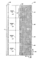
図5は、ターゲットの4パス印刷のための媒体送りキャリブレーションターゲット用マスクの一例400を示す。媒体送りキャリブレーションターゲット全体を印刷するには、4本より多いスワスを印刷することが必要である。この場合の4パス印刷とは、名目媒体送り距離について、印刷ヘッドの4分の1の部分の各々に含まれる対応するマーキング要素が、紙の特定の領域にドットを4層に(マスクの1に対応)堆積させることを意味する。 FIG. 5 shows an example 400 of a media advance calibration target mask for target four-pass printing. To print the entire media advance calibration target, it is necessary to print more than four swaths. In this case, four-pass printing means that, for the nominal medium feed distance, the corresponding marking elements included in each of the quarter portions of the print head have four layers of dots in a specific area of the paper (one mask). Means to deposit).
一例としてのマスク400は、マーキング要素アレイ420からのドットの発射を制御するのに用いられ、この場合、マーキング要素アレイ420は、たとえばブラックまたはシアンという1色のインクジェットノズル40本を有し、これらは媒体送り方向304に略平行なノズルアレイ方向254に沿って配置される。マスク400は、媒体送り方向304に沿って40行のエントリを有し、これらは40本のインクジェットノズルに対応する。40行は、媒体送りキャリブレーションターゲットの4パス印刷のための、それぞれ10列ずつの4つのゾーンに分離される。1と0のパターンは、4つのゾーンの各々について略同じである。一例としてのマスク400では、1は二次元クラスタ、特に2×2のクラスタ406として配置される。クラスタは、隔離領域407によって媒体送り方向304に沿って相互に分離され、隔離領域は、この例において、0の2×8の集合である。
The
マスク400の各行は、キャリッジ走査方向305に沿って10のエントリを有する。対応するノズルが記録媒体上の画素位置付近にあると、マスクは印刷ヘッドを、マスクの値1に対応する画素位置にドットを作るか、あるいはマスクの値0に対応する画素位置にドットを作らないように指示する。マスク400の行のエントリは10だけであるが、マスクは一般に、より大きな面積になるように連結され、印刷されるターゲットは40画素×10画素よりもっと大きくなる。
Each row of the
媒体送りキャリブレーションターゲットの4パス印刷(すなわち、m=4)の場合、まずノズル1−10が使用されて、1回目のパスで、キャリッジがキャリッジ走査方向305に沿って移動する間に、マスクの第一のゾーン401に対応する位置にドットが印刷される。具体的には、キャリッジ200が左から右に移動しているとき、マスク400の指示は、ノズル1,2がキャリッジ走査方向305に沿った第一と第二の画素位置で発射し、ノズル7,8がキャリッジ走査方向305に沿った第三、第四の画素位置で発射し、ノズル3,4がキャリッジ走査方向305に沿った第五、第六の画素位置で発射する、以下同様、のようになる。次に、媒体は、L/mに略等しい距離、すなわち約10画素分の間隔に、後述のオフセット量を加算した分だけ送られる。2回目のパスの印刷では、ノズル1−10は、用紙の中で前回マークされなかった領域に、マスクの第一のゾーン401に対応するパターンを印刷し、ノズル11−20は、ノズル1−10が印刷したばかりの、同じ領域に、マスク400の第二のゾーン402に対応するパターンを印刷する。その結果、ノズル11と12は、ノズル1,2により印刷されたばかりのドットクラスタの略上に4つのドットのクラスタを印刷し、以下同様である。その後、媒体は、L/mに略等しい距離、すなわち約10画素分の間隔に、今回もオフセット量を加算した分だけ送られる。3回目のパスの印刷中に、ノズル1−10は、用紙の中で前回マークされなかった領域に、マスクの第一のゾーン401に対応するパターンを印刷し、ノズル11−20は、ノズル1−10が印刷したばかりの、同じ領域に、マスク400の第二のゾーン402に対応するパターンを印刷し、ノズル21−30は、ノズル11−20が印刷したばかりの、同じ領域に、マスク400の第三のゾーン403に対応するパターンを印刷する。その後、媒体は、L/mに略等しい距離、すなわち約10画素分の間隔に、今回もオフセット量を加算した分だけ送られる。4回目のパスの印刷では、ノズル1−10は、用紙の中で前回マークされなかった領域に、マスクの第一のゾーン401に対応するバターンを印刷し、ノズル11−20は、ノズル1−10が印刷したばかりの、同じ領域に、マスク400の第二のゾーンに対応するパターンを印刷し、ノズル21−30は、ノズル11−20が印刷したばかりの、同じ領域に、マスク400の第三のゾーン403に対応するパターンを印刷し、ノズル31−40は、ノズル21−30が印刷したばかりの、同じ領域に、マスク400の第四のゾーン404に対応するパターンを印刷する。
In the case of four-pass printing of a medium feed calibration target (ie, m = 4), the nozzle 1-10 is used first, and the mask is moved during the first pass while the carriage moves along the
媒体送りキャリブレーションターゲットが印刷されるとき、媒体送りの量は、印刷システムおよび/または媒体の種類ごとに通常予想される媒体送り誤差の範囲を大きく外れるまで、増分的にスイープされる。1つの実施形態において、媒体送り距離は、1回の送りについて0.25画素の増分で、L/m−4画素からL/m+4画素までスイープされるようになっており、それによって媒体送りキャリブレーションターゲットに非常に特異な反射信号が供給され、これを走査して、正しい媒体送り校正の設定を自動的に判断することができる。言い換えれば、媒体送り量は、連続するパスにおいて、最小媒体送り距離がL/mより小さく、最大媒体送り距離がL/mより大きくなるように増減される。この実施形態では、媒体送り距離L/mは、媒体送りキャリブレーションターゲットの略中心である。L/mより大きい数値およびL/mより小さい数値までの媒体送りの増分は、ターゲットの中心に関して対称に配置される。これによって生成されるターゲットは、実際の媒体送りが名目媒体送りと等しければ、連続するパスにより印刷されるドットは媒体送りキャリブレーションターゲットの中心でほとんど完璧に重複するようなものとなる。したがって、実際にほとんど完璧に重複した地点(ターゲットの最大光反射により測定)とターゲットの物理的中心の間の距離が、実際の媒体送り誤差として測定できる値となる。名目媒体送り距離L/mが中心に位置づけられる必要はなく、またターゲットはスイープ増分において中心に関して対称である必要はないが、これがおそらく、ターゲットの設計として最も単純な形である。また、有効な校正スイープレンジは±4画素、すなわち送り増分が0.25画素に限定されることはなく、より広い、または狭いスイープレンジとする他の実施形態を使用するシステムも、適正な印刷マスキングとターゲット寸法を用いれば、有効である。 As the media advance calibration target is printed, the amount of media advance is incrementally swept until it is far outside the range of media advance errors normally expected for each printing system and / or media type. In one embodiment, the media feed distance is swept from L / m−4 pixels to L / m + 4 pixels in 0.25 pixel increments per feed, thereby causing media feed calibration. A very specific reflected signal is supplied to the target and can be scanned to automatically determine the correct media feed calibration setting. In other words, the medium feed amount is increased or decreased so that the minimum medium feed distance is smaller than L / m and the maximum medium feed distance is larger than L / m in successive passes. In this embodiment, the medium feed distance L / m is substantially the center of the medium feed calibration target. Media feed increments up to values greater than L / m and values less than L / m are arranged symmetrically with respect to the center of the target. The target generated by this is such that if the actual media feed is equal to the nominal media feed, the dots printed by successive passes will almost perfectly overlap at the center of the media feed calibration target. Therefore, the distance between the actually overlapped point (measured by the maximum light reflection of the target) and the physical center of the target is a value that can be measured as an actual medium feed error. The nominal media feed distance L / m need not be centered and the target need not be symmetric about the center in sweep increments, but this is probably the simplest form of target design. Also, the effective calibration sweep range is not limited to ± 4 pixels, i.e., the feed increment is limited to 0.25 pixels, and systems using other embodiments with wider or narrower sweep ranges are also suitable for printing. Use of masking and target dimensions is effective.
一例としてのマスク400のマスクドットパターンは、4つのドットのクラスタ、すなわちマスクの値が1の2×2のクラスタを示し、これはマスクの値が0の領域によって他のクラスタから分離される。このようなドットのクラスタでは、噴射の方向ずれ、キャリッジ速度誤差、印刷ヘッドから媒体までの間隔のばらつき、ノズルアレイの捻れによるドット位置誤差から生じる信号損失が低減されることがわかっている。しかしながら、この方法は、シングルピクセルドット(single pixel dot)または2×2のクラスタに配置された4つのドットより多いドットでも有効である。後述のように、クラスタが媒体送り方向に沿ってさらに長くなると(たとえば、2×3のクラスタ)、媒体の過剰送りまたは過小送りがかなり大きくても、媒体送りキャリブレーションターゲットにおいて、連続するパスで印刷されるドットクラスタの重複する部分が長くなる。
The mask dot pattern of the
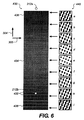
図6は、媒体送りキャリブレーションターゲット430のある実施形態(図では若干拡大)を示しており、このターゲットはマスク400と同様のマスク(ただし、40列ではなく640列であり、任意で、ドットクラスタパターンはマスク400に示されたものとは異なる)を使って、ノズル間隔が1/1200インチの640本のノズルのインクジェットノズルアレイによる4パス印刷で印刷されている。4パス印刷の場合の640本のノズルの印刷ヘッドの名目媒体送り距離は、640/4=160ノズル間隔、すなわち、160/1200インチ〜0.133”である。しかしながら、パターンの印刷中、媒体送り距離は、媒体送りキャリブレーションターゲット430の最上部の意図された156画素間隔(名目媒体送り距離から4画素間隔を引いたもの)から、意図された156.25画素間隔、156.5、156.75、157、…、159.75、160、160.25、…、163.5、163.75、最後に、媒体送りキャリブレーションターゲット430の最下部の意図された164画素間隔に増大される。言い換えれば、媒体送りキャリブレーションターゲット430の最上部に向かって、媒体は過小送り状態となり、その結果、隣接するスワスがある程度重複し、媒体送りキャリブレーションターゲット430の最下部に向かっては、媒体は過剰送り状態となり、その結果、隣接するスワスの間にある程度のギャップが生じる。ギャップは、比較的暗い背景に白い筋432として現れるため、特に判断しやすい。白い筋432は、ターゲットのこの領域における隣接する2つのスワスの境界を示す。
FIG. 6 shows an embodiment of the media advance calibration target 430 (slightly enlarged in the figure), which is a mask similar to the mask 400 (but 640 columns instead of 40 columns, optionally dot The cluster pattern is different from that shown in the mask 400), and is printed by four-pass printing using an inkjet nozzle array of 640 nozzles with a nozzle interval of 1/1200 inch. The nominal media feed distance of a 640 nozzle print head for 4-pass printing is 640/4 = 160 nozzle spacing, ie 160/1200 inches to 0.133 ″. However, during pattern printing, the media The feed distance is calculated from the intended 156 pixel spacing at the top of the media feed calibration target 430 (the nominal media feed distance minus the 4 pixel spacing) to the intended 156.25 pixel spacing, 156.5, 156 .75, 157, ..., 159.75, 160, 160.25, ..., 163.5, 163.75, and finally increased to the intended 164 pixel spacing at the bottom of the media
上記の説明の中で、異なる媒体送り距離を画素間隔の「意図された」数として記した。言い換えれば、送りローラ312のおおよその半径Roがわかっている状態で、送りローラ312はDCサーボモータによって、たとえば角度θ(送りローラシャフト319に取り付けられたロータリエンコーダによりモニタされる)だけ回転され、Roθが、たとえば156画素間隔等の意図された媒体送り量に等しくなるようにする。しかしながら、送りローラ312の製造ばらつきまたは摩耗により、送りローラ312の実際の半径Rは正確にRoと等しくないかもしれない。さらに、媒体の滑り等、送り誤差にはその他の原因もありうる。本発明では、さまざまな意図された媒体送り量を媒体が送られる実際の距離と関係づけ、その後、画像印刷中に過小送りと過剰送りを避けることができるように、媒体を送るべき正しい量を高い精度で示そうとするものである。
In the above description, different media feed distances have been noted as “intended” numbers of pixel spacing. In other words, in a state known to approximate the radius R o of the
図6の囲み440に、媒体送り誤差に関する、マルチパスで印刷されたスワス内の印刷ドットクラスタの大まかな外観を、拡大図a,b,c,…,iとして概略的に示す。これらの拡大図は、媒体送りキャリブレーションターゲット430の中心に向かってドットクラスタが相互に重複すると、より多くの白い紙の部分が出現し、ターゲットはその中心付近で明るい灰色、端部に向かって濃い灰色になるという効果を概略的に示している。媒体送り誤差に関するドットクラスタの実際の形態を以下に示す。
In FIG. 6, the outline appearance of the print dot cluster in the swath printed in the multi-pass related to the medium feeding error is schematically shown as enlarged views a, b, c,. These enlarged views show that when the dot clusters overlap each other toward the center of the media
図6には、キャリッジセンサ210の光センサの視野212も概略的に示されている。媒体送りキャリブレーションターゲット430を印刷した後に、キャリッジ200は、キャリッジセンサ210の視野212が、たとえば212aの位置でキャリブレーションターゲット430と並ぶまで、キャリッジ走査方向305に沿って移動される。その後、DCサーボモータが一定速度で送りローラ312を回転させ、それによって用紙は媒体送り方向304に沿って、略一定速度で移動される。媒体送りキャリブレーションターゲット430が視野212に関して移動される間に、光センサの信号がキャリブレーションターゲット430の中の名目位置に関して監視される。この名目位置は、送りローラシャフト319に取り付けられたロータリエンコーダによって提供される。光センサの信号は、視野212に入った白い紙の部分が多いと大きくなり、光センサの信号は、視野212において、用紙が印刷ドットによってカバーされる範囲が大きくなると小さくなる。したがって、光センサの信号は、端部領域436または438付近より、中央位置434付近でより大きくなる。任意で、光センサの信号を増幅して、アナログデジタルコンバータでデジタルデータに変換し、プリンタコントローラ14の中に、ロータリエンコーダにより提供される名目位置に関係づけて保存する。光センサの信号は、マークされていない用紙、たとえば視野が212aの位置にあるときに最高レベルとなる。図6に示される例では、視野212は直径約3mm(0.12”)であり、白い筋432の間の距離に関する視野の位置212bで示されているように、1本のスワス内に完全に収まる。
FIG. 6 also schematically shows the field 212 of the optical sensor of the
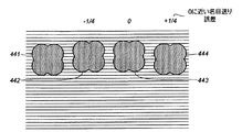
図7−10は、媒体送りキャリブレーションターゲット430のさまざまな領域に形成される、マルチパス方式で印刷されたドットクラスタの形状を拡大して示しており、2×2のドットクラスタの4パス印刷で、媒体送り増分は4分の1画素であることを前提としている。図7Aは、ターゲット430の、媒体送り誤差がゼロに近い位置434の付近の領域において、4回のパスの各々で印刷された2×2のドットクラスタの各々の垂直位置を示す。図7Aのドットクラスタは、相互から水平にずれ、個別に見ることができる。図7Bのドットクラスタ合成パターンは、各パスの後の重複するドットクラスタの外観を示す。点線は、4分の1画素間隔の間隔を示している。ドットクラスタ441は、たとえばノズル1,2によって、キャリッジ走査方向305に沿って2つの隣接する位置に印刷される。ドットクラスタの中の各ドットは、直径が約1.5画素間隔であり、対角線的に隣接するドットが重複する。ドットクラスタ446(1回のパスの後の合成パターン)は、ドットクラスタ441と同じである。ドットクラスタ442は、159.75画素間隔だけ媒体を送った後(すなわち、マイナス4分の1画素間隔の媒体送り誤差)に、ノズル161,162によって印刷され、ドットクラスタ441から4分の1画素だけ縦にずれている。ドットクラスタ合成体447は、ドットクラスタ441と重複するドットクラスタ442を示す。ドットクラスタ合成体447は、ドットクラスタ441,442の間に噴射の方向ずれがなく、ドットクラスタが重複する際、インクが拡散しない、という観点から理想化されている。媒体送りは、媒体送りキャリブレーションターゲット430の各スワスについて4分の1画素ずつ増加されるため、ドットクラスタ443の前の媒体送り量は160画素間隔であり、これは、640本の噴射ノズルアレイの4パス印刷のための名目上正しい媒体送りである。したがって、ドットクラスタ443(ノズル321,322により印刷される)はドットクラスタ442と同じ垂直位置にあり、ドットクラスタ合成体448は、ドットクラスタ443がドットクラスタ442の上に正確に着弾するため、ドットクラスタ合成体447とちょうど同じに見える。ドットクラスタ444がノズル481,482によって印刷される前に、媒体は160.25画素間隔(すなわち、プラス4分の1画素間隔の媒体送り誤差)だけ送られる。ドットクラスタ合成体449は、ドットクラスタ444がドットクラスタ441の上に正確に着弾するため、ドットクラスタ合成体447,448とちょうど同じに見える。ドットクラスタ合成体は、噴射の方向ずれがなく、実際の媒体送りが160画素間隔の名目媒体送りと略等しいことを前提とすれば、図6の囲みeのドットクラスタ合成体の実際の構成となる。
FIGS. 7-10 show enlarged shapes of dot clusters formed in various areas of the medium
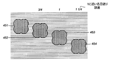
図8A,8Bは図7A,7Bと同様であるが、媒体送り誤差が約+1画素間隔の場合に関するものである。ドットクラスタ451はノズル1,2によって印刷され、1回のパスの後のドットクラスタ合成体456と同じである。ドットクラスタ452は、ドットクラスタ451から0.75画素間隔だけ縦にずれており、ドットクラスタ合成体457がカバーする紙の範囲はドットクラスタ合成体456より大きくなる。ドットクラスタ453は、ドットクラスタ452から1画素間隔だけ縦にずれ、ドットクラスタ451からは1.75画素間隔だけ縦にずれているため、ドットクラスタ合成体458はさらに大きくなる。最後に、ドットクラスタ454は、ドットクラスタ452から1.25画素間隔だけ縦にずれ、ドットクラスタ451からは3.0画素間隔だけ縦にずれている。4回のパスの後のドットクラスタ合成体459の最終的な外観は、ドットクラスタ合成体が名目上、図6の囲みd,fのように見えるものとなる。
8A and 8B are the same as FIGS. 7A and 7B, but relate to the case where the medium feeding error is about +1 pixel interval. The
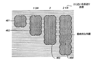
図9,10には、4回のパスの各々の後の、合成されたドットクラスタだけが示されている。ドットクラスタ合成体462は、461のようなドットクラスタと、461から1.75画素間隔だけ縦にずれた別のドットクラスタからなる。ドットクラスタ合成体463は、ドットクラスタ合成体462と、461から1.75+2.0=3.75画素間隔だけ縦にずれた別のドットクラスタからなる。ドットクラスタ合成体464は、ドットクラスタ合成体463と、461から6.0画素間隔だけ縦にずれた別のドットクラスタからなる。ドットクラスタ合成体464は最終的な外観は、ドットクラスタ合成体が名目上、図6の囲みc,gのように見えるものとなる。
In FIGS. 9 and 10, only the synthesized dot cluster after each of the four passes is shown. The
図10において、ドットクラスタ合成物472は、471のようなドットクラスタと、471から2.75画素間隔だけ縦にずれた別のドットクラスタからなる。注意すべき点として、ドットクラスタ合成体472を構成する2つのドットクラスタは、完全に相互に分離されている。これらは、もっと広がっても、それによってカバーされる紙の範囲は増えない。(これに対して、2×3のドットクラスタ構成の場合、クラスタ間にこれと同じ量のずれがあると、ドットクラスタ合成体はまだ重複する。)ドットクラスタ合成体473は、ドックラスタ複合体472と、471から2.75+3.0=5.75画素間隔だけ縦にずれた別のドットクラスタからなる。ドットクラスタ合成体474は、ドットクラスタ合成体473と、471から9.0画素間隔だけ縦にずれた別のドットクラスタからなる。ドットクラスタ合成体474の最終的な外観は、ドットクラスタ合成体が名目上、図6の囲みb,hのように見えるものとなる。
In FIG. 10, a
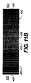
図6に関して上で説明したように、媒体送りキャリブレーションターゲット430が印刷された後、キャリッジ200は、キャリッジセンサ210がターゲット430と並ぶような位置に移動される。光センサのデータは、ロータリエンコーダによって提供される名目位置に関して保存される。図11Aは、光センサのデータとターゲット430に対応する位置との関係を示すグラフ530である。図11Bでは、ターゲット430を図6に関して時計回り方向に90度回転させ、グラフ530と略一致するようにし、グラフのさまざまな部分がターゲット430のさまざまな部分にどのように関係するかをより明確に理解できるようにしてある。
As described above with respect to FIG. 6, after the media
媒体送りキャリブレーションターゲット430の外側の領域431は白い紙であり、光センサの信号の最高値531(図11Aの例で示されるグラフ530の縦軸で620の数値)に対応する。ターゲット430が端部439から端部437に向かって走査される場合、ターゲット430が光センサの視野212により多く入るほど、光センサの信号が減少する。グラフ530の位置539で、縁辺439が光センサの視野212の中心にあり、信号レベルはその最大レベルと最小レベルの約中間まで減少する。同様に、グラフ530の位置537では、縁辺437が光センサの視野の中心にあり、信号レベルは再び、その最大レベルと最小レベルの間の約中間まで上昇する。
An
媒体送りキャリブレーションターゲットの、左縁辺439の付近の領域は、過剰送りが発生している(すなわち、160画素間隔より大きく送られる)領域であり、これによって白い筋432が入る。白い筋432が視野212に入ると、光センサの信号は、白い筋が視野から出るまで相応に増大する。白い筋432が光センサの視野212に入り、そこから出ることによって、データ曲線530の中にぎざぎざの段差532が生じる。
The area in the vicinity of the
媒体送りキャリブレーションターゲット430の地点433は、端部439と端部437の中間である。この中間点は、データグラフ530の地点533に対応する。地点533は、地点539と537の中間点を見つける(水平軸上の地点で示される)ことによって発見される。
A
反射データに関する光センサの信号のピーク535には、視野212の中心がターゲット430のもっとも明るい領域435に位置付けられた時に到達する。これは、ドットクラスタの重複が最大となる部分である。ターゲット430が対称に設計され、媒体送りが名目上正確であると、ピーク535は、図11Aのように中間点533からずれず、略中間点533に現れる。
The
グラフ530は、外観において、ピーク535と端部539の間より、ピーク535と端部537の間のほうが円滑である。これは、このターゲットのスワスの境界での反射の変化が、過小送りの場合では、濃い灰色の背景の白い筋432ほど明白でないからである。
The
ピーク地点535と中間点533の間の分離距離を使って、媒体送り誤差を計算することができる。図11Aの水平軸の目盛は1/600インチの単位である。図11Aの例において、ピーク535は2156の地点で現れ、中間点533は2000の地点である。したがって、ピーク535と中間点533の距離は156/600インチであり、これは312/1200インチと同じである。媒体送りは、約160/1200インチの各スワスについて0.25画素だけ増大されたため、またピーク535が中間点533の過小送り側にあるため、ピーク535に関して測定される所望の媒体送りは下式で求められる。
所望の媒体送り=160/1200”−(312/160)(0.25/1200”)〜160/1200”−0.4875/1200”
Using the separation distance between the
Desired media feed = 160/1200 "-(312/160) (0.25 / 1200") to 160/1200 "-0.4875 / 1200"
実際には、312/160という表現を使用すると、小さな誤差が生じる。これより若干よい計算は、比率312/160の160画素間隔の名目距離ではなく、ターゲット430の、中間点430とピーク位置435の間の過小送り側での媒体送りの平均画素間隔数を使用するものである。この場合、それは160と159.75の平均、すなわち159.875画素間隔である。しかしながら、誤差は1000分の1未満(すなわち、よりよい計算では、160/1200”−0.4879/1200”であり、所望の媒体送りに関して上に記した結果とほぼ同じ)である。
In practice, using the
この方法の試験を行った印刷システムでは、ロータリエンコーダの分解能が1画素間隔の12分の1、すなわち0.083/1200”に対応するため、この例では、その数値の半分に満たない(すなわち、0.0041/1200”)の誤差は無視できる。ピーク値535が右側の、図11Aのグラフの横軸の座標3000に対応する約3画素間隔の過小送りまでずれていたとしても(これは、ピークをピークとみなすことのできる、最も外側の位置)、計算に名目値160画素間隔を使用すると、無視できる誤差は、本出願人が用いた例のロータリエンコーダの分解能である1/12画素間隔の最近値となる。媒体送りが予め校正されていなくても、160画素間隔の名目値を計算に使用でき、そのロータリエンコーダにとって望ましい補正の判断において大きな誤差が生じない。
In the printing system where this method has been tested, the resolution of the rotary encoder corresponds to one-twelfth of a pixel spacing, ie 0.083 / 1200 ", so in this example less than half that number (ie , 0.0041 / 1200 ") is negligible. Even if the
したがって、上記の例において、正しい媒体送りを提供するために、ロータリエンコーダでの意図された数値は160画素間隔に対応するべきではなく、159.49画素間隔を159.5に丸めて、1/12画素間隔の最近値とする。これは、2分の1画素間隔の補正、すなわち、この例ではロータリエンコーダの分解能が1画素間隔の12分の1であるため、ロータリエンコーダ上で6カウントの補正である。したがって、適正なロータリエンコーダの回転は、マイナス6エンコーダカウントだけ調整して、適正に媒体送り量を提供するために、2分の1画素の補正値を求めることができる。言い換えれば、媒体送りのためのロータリエンコーダのカウントは160×12=1920ではなく、この例において、適正な媒体送りのために補正されたロータリエンコーダのカウントは1914となる。 Thus, in order to provide correct media advance in the above example, the intended value at the rotary encoder should not correspond to 160 pixel spacing, rounding the 159.49 pixel spacing to 159.5, 1 / The nearest value is an interval of 12 pixels. This is a correction of 1/2 pixel interval, that is, 6 count correction on the rotary encoder because the resolution of the rotary encoder is 1/12 of the 1 pixel interval in this example. Therefore, the correct rotary encoder rotation can be adjusted by minus 6 encoder counts, and a correction value of one-half pixel can be determined in order to properly provide the media feed amount. In other words, the rotary encoder count for media feeding is not 160 × 12 = 1920, and in this example, the rotary encoder count corrected for proper media feeding is 1914.
上述の例において、媒体送りキャリブレーションターゲット430のドットクラスタの重複量が最も大きいものは、反射率のピーク535として特定された。別の方法としては、ピーク535そのものではなく、ピーク領域の重心546を使用する。重心を使用した場合、たとえば、機械的振動によるドットの位置ずれの影響を減少させる、平均化の利点がある。図11Aの例において、重心546は、次のように計算した。まず、ピーク535に近い領域を選択する。これには、まず位置543の左と位置544の右のデータを切り捨てる。切り捨て位置543,544は、端部537,539の位置の内側の既知の距離(たとえば、水平軸上で200ユニット)となるように選択される。次に、閾値542を特定する。閾値542は、切り捨て位置543,544の間の最大値と最小値に基づいて選択できる。この例では、閾値542は、以下のように選択された。
閾値=最低値+0.25(最大値−最小値)〜200
In the above-described example, the medium
Threshold = minimum value + 0.25 (maximum value−minimum value) to 200
次に、重心計算の領域が、切り捨て位置543,544の間で閾値542を超える数値として選択される。続いて、閾値(200)を曲線530のこの領域のデータから差し引いて、ピーク領域曲線540を作る。重心の位置546は、曲線540の下の、重心546の左側の面積と、曲線540の下の、重心546の右側の面積とが等しい位置である。
Next, the center-of-gravity calculation region is selected as a numerical value exceeding the
図11Aの例において、重心546は、上記の計算で使用した、ピーク535の水平位置2156と比較して、水平位置2166に位置付けられる。したがって、重心546と中間点533の間の距離は、166/600インチであり、これは、332/1200インチと同じである。媒体送りは、約160/1200インチの各スワスについて0.25画素ずつ増大されたため、また、重心は中間点533の過小送り側にあるため、重心に関して測定される所望の媒体送りは下式で求められる。
所望の媒体送り=160/1200”−(332/160)(0.25/1200”)〜160/1200”−0.5188/1200”
In the example of FIG. 11A, the center of
Desired media feed = 160/1200 "-(332/160) (0.25 / 1200") to 160/1200 "-0.5188 / 1200"
12分の1画素間隔(ロータリエンコーダの分解能)の最近値まで、反射率重心方式で計算される補正は、したがってマイナス2分の1画素間隔(すなわち、マイナス6エンコーダカウント)であり、この例において、反射率ピーク方式の計算の場合と同じである。 The correction calculated with the reflectance centroid method up to the nearest value of 1/12 pixel spacing (rotary encoder resolution) is therefore minus 1/2 pixel spacing (ie minus 6 encoder counts), in this example This is the same as the calculation in the reflectance peak method.
媒体送りキャリブレーションターゲットのドットの印刷を制御する、図5の例のマスク400に戻ると、注意すべき点として、ゾーン401の中のマスクのエントリは、ゾーン402,403,404のマスクのエントリと同じである。このようなマスク設定は、マルチパス印刷によって印刷されたドットの重複が最も大きい領域について、露出する白い紙の量が最も大きく、光反射のピークは正しい媒体送りで現れる。しかしながら、この方法は、マスクのエントリがゾーン間で同一でなく、ゾーン間でほとんど同じであっても有効である。マスク400の例では、マスクの各ゾーンには100のエントリがあり、20個の1と80個の0からなる。100のエントリのすべてについて、ゾーン401の特定の位置に0があると、ゾーン402等の対応する位置に0があり、以下同様であり、これは1の位置についても同様である。1つのゾーンの中のマスクのエントリが第二のゾーンのエントリとまったく同じである必要はないが、マスクのエントリの75%より多くが第二のゾーンにおいて第一のゾーンと同じであると、この方法はより有効となる。
Returning to the
前述のように、マスク400の各ゾーンには、1が20個と0が80個ある。言い換えれば、マスクの各ゾーンにより、マークされるものとして指定される画素の数は、そのゾーンの画素の総数の20%である。1の数が比較的少ないマスクは、媒体送りが徐々に、増分的に過剰送りまたは過小送りとなるため、マークされた領域が他のマークされた領域と重なることがないという点で有利である。しかしながら、過小送りまたは過剰送りがどこまで増大されるか、等の要因に応じて、この方法は、マークされているゾーンの画素の20%を超える部分については依然として有効である。前述の2×3のクラスタは、マークされているゾーンの画素の30%に相当する。この方法は、マスクの各ゾーンによって、マークされるものとして指定される画素の数がそのゾーン内の画素の50%未満であれば、より有効である。
As described above, there are 20 1's and 80 0's in each zone of the
再び、図5−10の例を参照すると、1回のパスで印刷された2×2のマーキングクラスタは、媒体送り方向に沿った寸法Sを有し、Sは2間隔である。(印刷されたドットの直径は、垂直または水平画素間隔の1.414倍より少し大きく、ドットは対角線に沿って重複するが、マスクの対応する寸法Sは2画素間隔である。)媒体送り方向305(または、マーキング要素アレイ距離254)に沿ってマスク400の中の2×2の1のクラスタに隣接して、2×8の0の隔離領域がある。言い換えれば、隔離領域の媒体送り方向に沿った寸法は8画素間隔、すなわち4×Sである。隔離領域は4×Sと同じ大きさである必要はないが、この方法は、隔離領域の媒体送り方向に沿った寸法がSより大きいと、より有効である。さらに、マスク400において、隔離領域は0だけで構成される。隔離領域に1がないことは必要ではないが、この方法は、隔離領域内の画素の中で、マーキングに指定されるものが25%未満であると、より有効である。また、マークされた画素はドットクラスタにある必要はなく、あるいは各クラスタにおいて、媒体送り方向に隣接する画素のすべてが、マーキング用として指定される必要はないが、図5−10のドットクラスタはこの特性を有する。
Referring again to the example of FIGS. 5-10, a 2 × 2 marking cluster printed in one pass has a dimension S along the media feed direction, where S is 2 intervals. (The printed dot diameter is slightly larger than 1.414 times the vertical or horizontal pixel spacing, and the dots overlap along the diagonal, but the corresponding dimension S of the mask is two pixel spacing.) Media feed direction Adjacent to a 2 × 2 1 cluster in
前述の例における媒体送り増分の量(すなわち、連続するパスの間のオフセット量)は0.25画素間隔、すなわち0.25d(dは隣接するマーキング要素の距離)であった。0.25dをオフセット量(すなわち、連続するパスの媒体送り距離の増減量)として選択することは十分に有効であるが、別の選択も可能である。この方法は、オフセット量が2dより少ないときに、より有効である。 The amount of media advance increment in the previous example (ie, the amount of offset between successive passes) was 0.25 pixel spacing, ie 0.25d (d is the distance between adjacent marking elements). Although it is sufficiently effective to select 0.25d as the offset amount (that is, the amount of increase / decrease in the media feed distance of successive passes), another selection is possible. This method is more effective when the offset amount is less than 2d.
注目すべき点は、上記の例におけるロータリエンコーダの分解能に対応する名目媒体送りは1/12d、すなわち0.083dであり、これは連続するパスの媒体送り距離の増減量である0.25dより小さい。本発明によるプリンタの媒体送りの校正方法は、連続するパスにおける媒体送り距離の増減量より小さい補正値を特定できることが実証されている。いくつかの実施形態において、媒体送りスイープにおいて、ロータリエンコーダの分解能に対応する名目媒体送り距離(たとえば、0.083d)より大きいオフセット量(たとえば、0.25d)を使用することが有利である。これは、パターンを印刷するのに必要なスワスの数が少なくて済み、パターンがより小型化されるからである。さらに、このような媒体送りキャリブレーションターゲットは、パス間で、たとえば印刷システムの機械的振動から生じるドットの位置ずれ等によってノイズが発生する可能性が低くなる。 It should be noted that the nominal medium feed corresponding to the resolution of the rotary encoder in the above example is 1 / 12d, that is, 0.083d, which is from 0.25d, which is the amount of increase / decrease in the media feed distance of successive passes. small. It has been demonstrated that the media feeding calibration method of the printer according to the present invention can specify a correction value smaller than the increase / decrease amount of the media feeding distance in successive passes. In some embodiments, it is advantageous to use an offset amount (eg, 0.25d) that is greater than the nominal media feed distance (eg, 0.083d) corresponding to the resolution of the rotary encoder in the media feed sweep. This is because fewer swaths are required to print the pattern, and the pattern is made smaller. Further, such a medium feed calibration target is less likely to generate noise between passes due to, for example, dot displacement caused by mechanical vibration of the printing system.
正確さと都合を追求した結果、上記のように、媒体送りの校正を自動で行える実施形態が開発されたが、この方法は、手作業による校正の実施形態にも利用できる。 As a result of pursuing accuracy and convenience, as described above, an embodiment has been developed that can automatically calibrate the media feed. However, this method can also be used for a manual calibration embodiment.
上記の実施形態において、校正は、送りローラの角位置とは無関係の媒体送り誤差の成分を定量化し、補正するために行われる。いくつかの印刷システムの用途においては、送りローラが十分に丸く、機械的取付が十分に正確であるため、それ以外の補正は不要である。しかしながら、印刷システムによっては、送りローラは断面が正確に円形ではないかもしれず、また偏心的に取り付けられているかもしれず、あるいは、ぐらつきやノイズ、またはその他、送りローラの一定の角回転のための一定の媒体送り量からの偏差があるかもしれない。 In the above embodiment, the calibration is performed in order to quantify and correct the medium feed error component that is independent of the angular position of the feed roller. In some printing system applications, the feed roller is sufficiently round and the mechanical attachment is sufficiently accurate so that no other correction is necessary. However, depending on the printing system, the feed roller may not be exactly circular in cross-section and may be mounted eccentrically, or it may be wobble or noise, or otherwise for constant angular rotation of the feed roller. There may be deviations from a constant media feed.
上述の方法は、媒体送りにおける周期的変動またはノイズを定量化し、補正するために使用することができる。ロータリエンコーダの角度目盛に加え、ローラの特定の角位置を示すために、マーカ(たとえば、ロータリエンコーダの一部であってもよい)が設けられる。この場合、第一のステップは、媒体送りを校正して、誤差のうち、角位置と関係のない成分が、たとえば上の実施形態で説明したように、媒体送り量の範囲について、ドットクラスタの重複による光反射を測定することによって定量化される。次に、同じマスク(たとえば、一例としてのマスク400)を使用するが、この場合、スワス間の媒体送り量を、誤差のうちの、角位置に無関係の成分の測定結果(すなわち、媒体送りを増分的にスイープせず、補正された数値で一定に保つ)に基づく補正された量に設定する。ターゲットを印刷した後に、キャリッジ200をターゲットと一致させ、媒体がそこを通過して送られる間に、キャリッジセンサ210を使って走査できるようにする。位置に関する光反射を測定し、この位置は、ローラの特定の角位置を示すマーカに関連付けられる。ローラに大きな逃げや偏心のある印刷システムでは、反射率が周期的に変化する(正弦波的変動)。次に、位置に関する光反射データを使って、ローラ位置に関してローラを回転させるためのエンコーダの適正なカウント数を特徴付けることができる。名目媒体送り距離が160/1200”または1920エンコーダカウントに対応するが、補正された媒体送り距離が1914エンコーダカウント(上記の例と同様)に対応するものと仮定する。角度依存性の測定において、ローラマーカに関して0度では、適正な媒体送り距離が1916エンコーダカウントに対応し、90度では1914、180度では1912、270度では1914である(ローラ1回転の全体の平均は1914である)ことがわかるかもしれない。これらの角度変化は、プリンタのコントローラ14のテーブルに保存し、ローラの角位置に関する媒体送り距離の補正に使用することができる。
The method described above can be used to quantify and correct periodic variations or noise in the media feed. In addition to the rotary encoder angle scale, a marker (eg, may be part of the rotary encoder) is provided to indicate a particular angular position of the roller. In this case, the first step is to calibrate the media feed, and the component of the error that is not related to the angular position is, for example, as described in the above embodiment, for the range of the media feed amount of the dot cluster. Quantified by measuring light reflection due to overlap. Next, the same mask (for example,
上記の校正は、工場で、または使用者が行うことができる。工場で過剰なノイズまたは振動が発見された場合(ターゲットの反射率の過剰な変化として検出される)、そのアセンブリは、工場から出荷する前に、再加工するか、不合格としてはねることができる。 The above calibration can be done at the factory or by the user. If excessive noise or vibration is found at the factory (detected as an excessive change in target reflectivity), the assembly can be reworked or rejected before it is shipped from the factory. .
10 インクジェットプリンタシステム、12 画像データ供給源、14 コントローラ、15 画像処理ユニット、16 電気パルス発生源、18 第一の流体供給源、19 第二の流体供給源、20 記録媒体、100 インクジェット印刷ヘッド、110 インクジェット印刷ヘッドダイ、111 基板、120 第一のノズルアレイ、121 第一のノズルアレイのノズル、122 第一のノズルアレイのためのインク供給経路、130 第二のノズルアレイ、131 第二のノズルアレイのノズル、132 第二のノズルアレイのためのインク供給経路、181 第一のノズルアレイから吐出される小滴、182 第二のノズルアレイから吐出される小滴、200 キャリッジ、210 キャリッジセンサ、212 キャリッジセンサの視野、250 印刷ヘッド筐体、251 印刷ヘッドダイ、253 ノズルアレイ、254 ノズルアレイの方向、256 封入材、257 フレキシブル回路、258 コネクタ基板、262 マルチチャンバインク供給源、264 シングルチャンバインク供給源、300 プリンタ筐体、302 用紙充填入口、303 印刷領域、304 媒体送り方向、305 キャリッジ走査方向、306 プリンタ筐体右側、307 プリンタ筐体左側、308 プリンタ筐体の前部、309 プリンタ筐体の後部、310 紙送りモータ駆動歯車のための穴、311 送りローラ歯車、312 送りローラ、313 送りローラの前進回転、319 送りローラシャフト、320 ピックアップローラ、322 方向転換ローラ、323 アイドラローラ、324 放電ローラ、325 星形車、330 メンテナンスステーション、370 媒体のスタック、371 最も上のシート、372 主要用紙トレイ、373 写真用紙のスタック、374 写真用紙トレイ、376 用紙トレイの陥凹部、380 キャリッジモータ、382 キャリッジレール、383 エンコーダフェンス、384 ベルト、390 プリンタ電子機器基板、392 ケーブルコネクタ、400 媒体送りキャリブレーションターゲットのマスク、401 マスクの第一のゾーン、402 マスクの第二のゾーン、403 マスクの第三のゾーン、404 マスクの第四のゾーン、406 クラスタ、407 隔離領域、420 マーキング要素アレイ、430 媒体送りキャリブレーションターゲット、431 ターゲットの外側領域、432 過剰送りによる白い筋、433 ターゲットの端部間の中間点、434 ターゲットの中心点、435 ターゲットの最も明るい領域、436 ターゲットの端部領域、437 ターゲットの端、438 ターゲットの端部領域、439 ターゲットの端、441,442,443,444 ドットクラスタ、446,447,448,449 ドットクラスタ合成体、451,452,453,454 ドットクラスタ、456,457,458,459 ドットクラスタ合成体、461,462,463,464 ドットクラスタ合成体、471,472,473,474 ドットクラスタ合成体、530 光センサのデータのグラフ、531 領域431の光センサのデータ、532 白い筋432に対応するデータの段差、533 ターゲット中心433に対応する光センサのデータ、535 反射率データのピーク、537 端部437が視野の中心にあるときの光センサのデータ、539 端部439が視野の中心にあるときの光センサのデータ、540 ピーク領域の曲線、542 閾値、543,544 切り捨て位置、546 ピーク領域の重心。 DESCRIPTION OF SYMBOLS 10 Inkjet printer system, 12 Image data supply source, 14 Controller, 15 Image processing unit, 16 Electric pulse generation source, 18 First fluid supply source, 19 Second fluid supply source, 20 Recording medium, 100 Inkjet print head, 110 Inkjet printhead die, 111 substrate, 120 first nozzle array, 121 nozzle of first nozzle array, 122 ink supply path for first nozzle array, 130 second nozzle array, 131 second nozzle array 132, ink supply path for the second nozzle array, 181 droplets ejected from the first nozzle array, 182 droplets ejected from the second nozzle array, 200 carriage, 210 carriage sensor, 212 Carriage sensor field of view, 2 0 print head housing, 251 print head die, 253 nozzle array, 254 nozzle array orientation, 256 encapsulant, 257 flexible circuit, 258 connector board, 262 multi-chamber ink supply, 264 single chamber ink supply, 300 printer housing , 302 Paper filling inlet, 303 Print area, 304 Media feed direction, 305 Carriage scanning direction, 306 Printer housing right side, 307 Printer housing left side, 308 Printer housing front, 309 Printer housing rear, 310 Paper feed Hole for motor drive gear, 311 feed roller gear, 312 feed roller, 313 feed roller forward rotation, 319 feed roller shaft, 320 pickup roller, 322 direction change roller, 323 idler roller, 324 discharge roller 325 star car, 330 maintenance station, 370 media stack, 371 top sheet, 372 main paper tray, 373 photo paper stack, 374 photo paper tray, 376 paper tray recess, 380 carriage motor, 382 Carriage rail, 383 Encoder fence, 384 belt, 390 Printer electronics board, 392 Cable connector, 400 Media feed calibration target mask, 401 Mask first zone, 402 Mask second zone, 403 Mask first Three zones, 404 fourth zone of mask, 406 clusters, 407 isolation region, 420 marking element array, 430 media feed calibration target, 431 outer region of target, 432 White streaks due to overfeed, 433 Midpoint between target edges, 434 Target center point, 435 Target brightest area, 436 Target edge area, 437 Target edge, 438 Target edge area, 439 Target 441, 442, 443, 444 dot cluster, 446, 447, 448, 449 dot cluster composite, 451, 452, 453, 454 dot cluster, 456, 457, 458, 459 dot cluster composite, 461, 462 , 463, 464 Dot cluster composite, 471, 472, 473, 474 Dot cluster composite, 530 Photosensor data graph, 531 Photosensor data in region 431, 532 Data level corresponding to white streak 432, 533 target Optical sensor data corresponding to the heart 433, 535 reflectance data peak, 537 optical sensor data when the end 437 is at the center of the field of view, 539 optical sensor data when the end 439 is at the center of the field of view 540 Peak area curve, 542 threshold, 543, 544 truncation position, 546 Peak area centroid.
Claims (19)
キャリブレーションターゲットの印刷設定を特定するマスクを提供するステップと、
印刷媒体上に媒体送りキャリブレーションターゲットを、
i.前記マーキング要素アレイを使って、印刷媒体上に前記キャリブレーションターゲットを印刷するステップ、
ii.前記印刷媒体を、媒体送り量だけ送るステップ、
iii.前記マーキング要素アレイを使って、前記印刷媒体上に前記キャリブレーションターゲットを印刷するステップ、
iv.前記印刷媒体を、前回の媒体送り量にオフセット量を加算した分だけ送るステップ、
v.ステップiiiとivを繰り返し、前記媒体送りキャリブレーションターゲットを完成させるステップ
によって印刷するステップと、
前記媒体送りキャリブレーションターゲットの光反射を、前記媒体送りキャリブレーションターゲットに沿った位置に関して測定するステップと、
前記媒体送りキャリブレーションターゲットに沿った、前記光反射が最大であった位置に対応する位置を特定するステップと、
前記光反射が最大であった位置を、前記媒体送りキャリブレーションターゲットの所定の位置と比較して、前記プリンタ内の媒体送りを校正するステップと、
を含むことを特徴とする方法。 A method for calibrating a media feed of a printer, the printer comprising a marking element array disposed along a direction substantially parallel to the media feed direction;
Providing a mask identifying print settings of the calibration target;
A media feed calibration target on the print media,
i. Printing the calibration target on a print medium using the marking element array;
ii. Sending the print medium by a medium feed amount;
iii. Printing the calibration target on the print medium using the marking element array;
iv. Sending the print medium by the amount of offset added to the previous medium feed amount;
v. Printing by the steps of repeating steps iii and iv and completing the media advance calibration target;
Measuring light reflection of the media advance calibration target with respect to a position along the media advance calibration target;
Identifying a position along the medium feed calibration target corresponding to the position where the light reflection was maximum;
Calibrating the media feed in the printer by comparing the position where the light reflection was maximum with a predetermined position of the media feed calibration target;
A method comprising the steps of:
前記媒体送りキャリブレーションターゲットに沿った、前記光反射が最大であった位置に対応する位置を特定するステップは、前記光反射のピークの位置を特定するステップを含むことを特徴とする方法。 The method of claim 1, comprising:
The method of identifying a position along the medium feed calibration target corresponding to a position where the light reflection is maximum includes identifying a position of the light reflection peak.
前記媒体送りキャリブレーションターゲットに沿った、前記光反射が最大であった位置に対応する位置を特定するステップは、前記光反射の重心を分析するステップを含むことを特徴とする方法。 The method of claim 1, comprising:
The method of identifying a position along the media advance calibration target that corresponds to the position at which the light reflection was maximal comprises analyzing a center of gravity of the light reflection.
前記印刷媒体上に、前記マーキング要素アレイを使って前記キャリブレーションターゲットを印刷するステップは、m回のパスを含むマルチパスモードを使って前記キャリブレーションターゲットを印刷するステップを含み、前記マスクは、各パスでマークされる画素とマークされない画素の位置を特定し、前記キャリブレーションターゲットの画素位置が第一のパスで第一のマーキング要素によって印刷され、前記キャリブレーションターゲットの前記同じ画素位置は第二のパスで第二のマーキング要素によって印刷されるように構成されていることを特徴とする方法。 The method of claim 1, comprising:
Printing the calibration target on the print medium using the marking element array includes printing the calibration target using a multi-pass mode including m passes, the mask comprising: Identify the positions of the marked and unmarked pixels in each pass, the pixel position of the calibration target is printed by the first marking element in the first pass, and the same pixel position of the calibration target is the first A method configured to be printed by a second marking element in two passes.
前記マスクは、m個のゾーンを有するように構成され、第一のゾーンのマスクエントリの75%より多くが第二のゾーンの対応位置のマスクエントリと同じであることを特徴とする方法。 The method of claim 4, comprising:
The method is characterized in that the mask is configured to have m zones, and more than 75% of the mask entries in the first zone are the same as the mask entries in the corresponding positions in the second zone.
前記マスクの各ゾーンによって、マークされるものとして指定される画素の数が、前記ゾーンの画素総数の50%未満であることを特徴とする方法。 6. A method according to claim 5, wherein
The method wherein the number of pixels designated as marked by each zone of the mask is less than 50% of the total number of pixels in the zone.
前記マスクの各ゾーンは、
マークされるものと指定された複数の画素を含むマーキングクラスタであって、前記媒体送り方向に沿って寸法Sを有するマーキングクラスタと、
前記媒体送り方向に沿って前記マーキングクラスタに隣接する隔離領域であって、前記媒体送り方向に沿ってSより大きい寸法を有し、前記隔離領域の前記画素の25%未満がマーキング用として指定されている隔離領域と、
を含むことを特徴とする方法。 6. A method according to claim 5, wherein
Each zone of the mask is
A marking cluster comprising a plurality of pixels designated to be marked, the marking cluster having a dimension S along the media feed direction;
An isolation region adjacent to the marking cluster along the media feed direction and having a dimension greater than S along the media feed direction, wherein less than 25% of the pixels of the isolation region are designated for marking An isolated area,
A method comprising the steps of:
前記マーキングクラスタは、前記媒体送り方向に沿って隣接する複数の画素からなり、前記隣接する複数の画素の各々は、マーキング用として指定されることを特徴とする方法。 The method of claim 7, comprising:
The marking cluster includes a plurality of adjacent pixels along the medium feeding direction, and each of the adjacent plurality of pixels is designated for marking.
前記マーキングクラスタは、マークされるものとして指定される画素の二次元集合からなることを特徴とする方法。 The method of claim 7, comprising:
The method wherein the marking cluster consists of a two-dimensional set of pixels designated as marked.
前記キャリブレーションターゲットを印刷するのに使用される前記マーキング要素アレイは長さがLであり、
前記媒体送り量は、連続するパスにおいて、最小媒体送り距離がL/m未満であり、最大媒体送り距離がL/mより大きくなるように増減されることを特徴とする方法。 The method of claim 4, comprising:
The marking element array used to print the calibration target is L in length;
The method is characterized in that the medium feed amount is increased or decreased so that the minimum medium feed distance is less than L / m and the maximum medium feed distance is greater than L / m in successive passes.
隣接するマーキング要素の間の距離はdであり、
連続するパスにおける前記媒体送り距離の増減の量は2d未満であることを特徴とする方法。 The method of claim 10, comprising:
The distance between adjacent marking elements is d;
The method according to claim 1, wherein the amount of increase / decrease in the medium feeding distance in consecutive passes is less than 2d.
前記プリンタ内の媒体送りを校正するための前記媒体送りキャリブレーションターゲットの所定の位置は、L/mと等しい媒体送り距離に対応することを特徴とする方法。 The method of claim 10, comprising:
A method wherein the predetermined position of the media feed calibration target for calibrating media feed in the printer corresponds to a media feed distance equal to L / m.
前記マスクは複数のゾーンを有するように構成され、
前記マスクの各ゾーンは、
マークされるものとして指定される複数の画素を含むマーキングクラスタからなり、前記マスクの異なるゾーンに従って異なるマーキング要素により印刷されたマーキングクラスタの間の重複の程度は、前記媒体送り距離によって変化し、前記光反射は、前記重複の程度が増加すると増大することを特徴とする方法。 The method of claim 1, comprising:
The mask is configured to have a plurality of zones;
Each zone of the mask is
A marking cluster comprising a plurality of pixels designated as marked, the degree of overlap between marking clusters printed by different marking elements according to different zones of the mask varies with the media feed distance, Light reflection increases as the degree of overlap increases.
前記媒体送りキャリブレーションターゲットは中心を有し、
前記媒体送りキャリブレーションターゲットの前記所定の位置は前記ターゲットの前記中心であることを特徴とする方法。 The method of claim 1, comprising:
The media advance calibration target has a center;
The method of claim 1, wherein the predetermined position of the media advance calibration target is the center of the target.
前記媒体送りキャリブレーションターゲットの、前記媒体送りキャリブレーションターゲットに沿った位置に関する前記光反射を測定するステップは、光学センサを使って前記媒体送りキャリブレーションターゲットを走査するステップを含むことを特徴とする方法。 The method of claim 1, comprising:
Measuring the light reflection of the media advance calibration target with respect to a position along the media advance calibration target includes scanning the media advance calibration target using an optical sensor. Method.
前記プリンタはさらに、
媒体送りローラと、
前記媒体送りローラと同軸的に取り付けられたロータリエンコーダと、
をさらに備え、前記ロータリエンコーダは分解能を有し、前記オフセット量は、前記ロータリエンコーダの前記分解能に対応する名目媒体送り量より大きいことを特徴とする方法。 The method of claim 1, comprising:
The printer further includes:
A medium feed roller;
A rotary encoder mounted coaxially with the medium feed roller;
The rotary encoder has a resolution, and the offset amount is larger than a nominal medium feed amount corresponding to the resolution of the rotary encoder.
前記方法は、
前記媒体送りローラの回転を前記校正された媒体送りに基づいて調整するステップをさらに含むことを特徴とする方法。 The method of claim 1, wherein the printer comprises a media feed roller,
The method
Adjusting the rotation of the media feed roller based on the calibrated media feed.
前記方法は、
前記印刷媒体上に第二の媒体送りキャリブレーションターゲットを、
i.前記マーキング要素アレイを使って、印刷媒体上に前記キャリブレーションターゲットを印刷するステップ、
ii.前記印刷媒体を、媒体送り量だけ送るステップ、
iii.前記マーキング要素アレイ使って、前記印刷媒体上に前記キャリブレーションターゲットを印刷するステップ、
iv.前記印刷媒体を、前回の媒体送り量だけ送るステップ、
v.ステップiiiとivを繰り返し、前記媒体送りキャリブレーションターゲットを完成させるステップ
によって印刷するステップと、
前記第二の媒体送りキャリブレーションターゲットの光反射を、前記第二の媒体送りキャリブレーションターゲットに沿った位置に関して測定するステップと、
角回転に関して光反射の周期的な変動を特定し、記憶するステップと、
前記記憶された周期的変動およびローラの特定の角位置を示す前記マーカの位置に基づいて、前記媒体送りローラの回転を調整するステップと、
を含むことを特徴とする方法。 The method of claim 1, wherein the printer comprises a media feed roller and a marker that indicates a particular angular position of the roller;
The method
A second media advance calibration target on the print medium,
i. Printing the calibration target on a print medium using the marking element array;
ii. Sending the print medium by a medium feed amount;
iii. Printing the calibration target on the print medium using the marking element array;
iv. Sending the print medium by the previous medium feed amount;
v. Printing by the steps of repeating steps iii and iv and completing the media advance calibration target;
Measuring the light reflection of the second media advance calibration target with respect to a position along the second media advance calibration target;
Identifying and storing periodic fluctuations in light reflection with respect to angular rotation;
Adjusting the rotation of the media feed roller based on the stored periodic variation and the position of the marker indicating a particular angular position of the roller;
A method comprising the steps of:
前記方法は、
キャリブレーションターゲットの印刷設定を特定するマスクを提供するステップと、
印刷媒体上に媒体送りキャリブレーションターゲットを、
i.前記マーキング要素アレイを使って、印刷媒体上に前記キャリブレーションターゲットを印刷するステップ、
ii.前記印刷媒体を、媒体送り量だけ送るステップ、
iii.前記マーキング要素アレイを使って、前記印刷媒体上に前記キャリブレーションターゲットを印刷するステップ、
iv.前記印刷媒体を、前回の媒体送り量だけ送るステップ、
v.ステップiiiとivを繰り返し、前記媒体送りキャリブレーションターゲットを完成させるステップ
によって印刷するステップと、
前記媒体送りキャリブレーションターゲットの光反射を、前記媒体送りキャリブレーションターゲットに沿った位置に関して測定するステップと、
前記角回転に関して光反射の周期的な変動を特定し、記憶するステップと、
前記記憶された周期的変動および前記ローラの特定の角位置を示す前記マーカの位置に基づいて、前記媒体送りローラの回転を調整するステップと、
を含むことを特徴とする方法。
A method of calibrating media feed in a printer, the printer comprising a media feed roller, a marker indicating a particular angular position of the roller, and a marking element array arranged along a direction substantially parallel to the media feed direction ,
The method
Providing a mask identifying print settings of the calibration target;
A media feed calibration target on the print media,
i. Printing the calibration target on a print medium using the marking element array;
ii. Sending the print medium by a medium feed amount;
iii. Printing the calibration target on the print medium using the marking element array;
iv. Sending the print medium by the previous medium feed amount;
v. Printing by the steps of repeating steps iii and iv and completing the media advance calibration target;
Measuring light reflection of the media advance calibration target with respect to a position along the media advance calibration target;
Identifying and storing periodic fluctuations in light reflection with respect to the angular rotation;
Adjusting the rotation of the media feed roller based on the stored periodic variation and the position of the marker indicating a particular angular position of the roller;
A method comprising the steps of:
Applications Claiming Priority (3)
| Application Number | Priority Date | Filing Date | Title |
|---|---|---|---|
| US12/241,112 US7762642B2 (en) | 2008-09-30 | 2008-09-30 | Media advance calibration |
| US12/241,112 | 2008-09-30 | ||
| PCT/US2009/005351 WO2010039204A1 (en) | 2008-09-30 | 2009-09-28 | Media advance calibration |
Publications (2)
| Publication Number | Publication Date |
|---|---|
| JP2012504061A true JP2012504061A (en) | 2012-02-16 |
| JP2012504061A5 JP2012504061A5 (en) | 2012-11-08 |
Family
ID=41404388
Family Applications (1)
| Application Number | Title | Priority Date | Filing Date |
|---|---|---|---|
| JP2011529027A Pending JP2012504061A (en) | 2008-09-30 | 2009-09-28 | Media feed calibration |
Country Status (4)
| Country | Link |
|---|---|
| US (2) | US7762642B2 (en) |
| EP (1) | EP2328760A1 (en) |
| JP (1) | JP2012504061A (en) |
| WO (1) | WO2010039204A1 (en) |
Families Citing this family (10)
| Publication number | Priority date | Publication date | Assignee | Title |
|---|---|---|---|---|
| US8864393B2 (en) | 2010-06-21 | 2014-10-21 | Hewlett-Packard Development Company, L.P. | Media advance |
| US8246137B2 (en) | 2010-07-30 | 2012-08-21 | Hewlett-Packard Development Company, L.P. | Image forming apparatus and methods thereof |
| US9539835B2 (en) * | 2012-11-29 | 2017-01-10 | Hewlett-Packard Development Company, L.P. | Calibration apparatus |
| US9102178B2 (en) | 2013-01-30 | 2015-08-11 | Hewlett-Packard Development Company, L.P. | Multi-region media advance compensation |
| US9539829B2 (en) * | 2013-10-31 | 2017-01-10 | Hewlett-Packard Development Company, L.P. | Printing on a media web |
| EP2960062B1 (en) * | 2014-06-26 | 2017-02-01 | OCE-Technologies B.V. | Method for calibrating accurate paper steps |
| US9844956B2 (en) * | 2015-10-07 | 2017-12-19 | Intermec Technologies Corporation | Print position correction |
| US9643405B1 (en) * | 2016-08-01 | 2017-05-09 | Xerox Corporation | System and method for aligning images on media or platens |
| KR101884997B1 (en) * | 2016-10-20 | 2018-08-03 | 주식회사 빅솔론 | Method for controlling printer and the printer therefore |
| WO2022010459A1 (en) * | 2020-07-07 | 2022-01-13 | Hewlett-Packard Development Company, L.P. | Print media advance calibration |
Citations (2)
| Publication number | Priority date | Publication date | Assignee | Title |
|---|---|---|---|---|
| JP2006272957A (en) * | 2005-03-04 | 2006-10-12 | Canon Inc | Recording apparatus and recording method |
| JP2007261262A (en) * | 2006-03-02 | 2007-10-11 | Canon Inc | Recording device and recording method |
Family Cites Families (10)
| Publication number | Priority date | Publication date | Assignee | Title |
|---|---|---|---|---|
| US5825378A (en) | 1993-04-30 | 1998-10-20 | Hewlett-Packard Company | Calibration of media advancement to avoid banding in a swath printer |
| US6137592A (en) | 1998-01-20 | 2000-10-24 | Hewlett-Packard Company | Method for adjusting drive roller linefeed distance |
| US6076915A (en) * | 1998-08-03 | 2000-06-20 | Hewlett-Packard Company | Inkjet printhead calibration |
| US6940618B2 (en) | 2000-11-29 | 2005-09-06 | Hewlett-Packard Development Company, L.P. | Linefeed calibration method for a printer |
| JP4174764B2 (en) * | 2003-08-21 | 2008-11-05 | セイコーエプソン株式会社 | Paper feed error detecting device, printing apparatus, and paper feed error detecting method |
| US7021732B2 (en) * | 2003-11-12 | 2006-04-04 | Xerox Corporation | Printer jet detection method and apparatus |
| US7210758B2 (en) | 2005-01-04 | 2007-05-01 | Eastman Kodak Company | Media feed calibration |
| JP2006256302A (en) * | 2005-02-21 | 2006-09-28 | Canon Finetech Inc | Paper feeding amount adjustment method and ink jet type image forming apparatus |
| US7380898B2 (en) * | 2005-10-03 | 2008-06-03 | Hewlett-Packard Development Company, L.P. | Calibration method for a printer |
| JP5084333B2 (en) * | 2007-04-10 | 2012-11-28 | キヤノン株式会社 | Recording apparatus and conveyance error correction value acquisition method |
-
2008
- 2008-09-30 US US12/241,112 patent/US7762642B2/en active Active
-
2009
- 2009-09-28 JP JP2011529027A patent/JP2012504061A/en active Pending
- 2009-09-28 WO PCT/US2009/005351 patent/WO2010039204A1/en active Application Filing
- 2009-09-28 EP EP20090736500 patent/EP2328760A1/en not_active Withdrawn
-
2010
- 2010-07-09 US US12/833,060 patent/US20100271416A1/en not_active Abandoned
Patent Citations (2)
| Publication number | Priority date | Publication date | Assignee | Title |
|---|---|---|---|---|
| JP2006272957A (en) * | 2005-03-04 | 2006-10-12 | Canon Inc | Recording apparatus and recording method |
| JP2007261262A (en) * | 2006-03-02 | 2007-10-11 | Canon Inc | Recording device and recording method |
Also Published As
| Publication number | Publication date |
|---|---|
| EP2328760A1 (en) | 2011-06-08 |
| WO2010039204A1 (en) | 2010-04-08 |
| US20100271416A1 (en) | 2010-10-28 |
| US7762642B2 (en) | 2010-07-27 |
| US20100078870A1 (en) | 2010-04-01 |
Similar Documents
| Publication | Publication Date | Title |
|---|---|---|
| JP2012504061A (en) | Media feed calibration | |
| US8439472B2 (en) | Printing apparatus and method of acquiring correction value of conveying error | |
| JP4273126B2 (en) | Recording apparatus and correction method | |
| US8251475B2 (en) | Position detection with two-dimensional sensor in printer | |
| US8523310B2 (en) | Printing apparatus and printing method | |
| US7845751B2 (en) | Nonuniform mask circulation for irregular page advance | |
| JP2010269527A (en) | Image recording apparatus and control method thereof | |
| EP1645421B1 (en) | Ink jet printer | |
| JPWO2004011262A1 (en) | Liquid ejecting apparatus and printing system | |
| EP2933108B1 (en) | Recording device | |
| US8317292B2 (en) | Method of position detection with two-dimensional sensor in printer | |
| US7891757B2 (en) | Marking element registration | |
| JP6319948B2 (en) | Recording device | |
| JP5915166B2 (en) | Printing apparatus and correction method | |
| JP2011051207A (en) | Inkjet recorder and recording position adjusting method | |
| JP2010221404A (en) | Inkjet recorder | |
| US7093916B2 (en) | Liquid ejection method and liquid ejecting apparatus | |
| JP4591013B2 (en) | Printing apparatus, printing method, program, and printing system | |
| JP2012187742A (en) | Inkjet recording apparatus | |
| JP2012125974A (en) | Inkjet recording apparatus | |
| JP2008302624A (en) | Manufacturing method of liquid discharge apparatus, adjusting method of liquid discharge apparatus, liquid discharge apparatus and liquid discharge method of liquid discharge apparatus | |
| JP4507544B2 (en) | Printing operation state determination system, printing operation state determination method, optical sensor adjustment system, and optical sensor adjustment method | |
| JP4265235B2 (en) | Test pattern, test pattern creation method, recording apparatus and program | |
| JP2005125505A (en) | Image forming apparatus | |
| JP2005103995A (en) | System and method for determining printing operation state, and system and method for adjusting optical sensor |
Legal Events
| Date | Code | Title | Description |
|---|---|---|---|
| A521 | Request for written amendment filed |
Free format text: JAPANESE INTERMEDIATE CODE: A523 Effective date: 20120920 |
|
| A621 | Written request for application examination |
Free format text: JAPANESE INTERMEDIATE CODE: A621 Effective date: 20120920 |
|
| A977 | Report on retrieval |
Free format text: JAPANESE INTERMEDIATE CODE: A971007 Effective date: 20130912 |
|
| A02 | Decision of refusal |
Free format text: JAPANESE INTERMEDIATE CODE: A02 Effective date: 20140401 |