JP4507544B2 - Printing operation state determination system, printing operation state determination method, optical sensor adjustment system, and optical sensor adjustment method - Google Patents
Printing operation state determination system, printing operation state determination method, optical sensor adjustment system, and optical sensor adjustment method Download PDFInfo
- Publication number
- JP4507544B2 JP4507544B2 JP2003341406A JP2003341406A JP4507544B2 JP 4507544 B2 JP4507544 B2 JP 4507544B2 JP 2003341406 A JP2003341406 A JP 2003341406A JP 2003341406 A JP2003341406 A JP 2003341406A JP 4507544 B2 JP4507544 B2 JP 4507544B2
- Authority
- JP
- Japan
- Prior art keywords
- printing
- optical sensor
- light
- print medium
- Prior art date
- Legal status (The legal status is an assumption and is not a legal conclusion. Google has not performed a legal analysis and makes no representation as to the accuracy of the status listed.)
- Expired - Fee Related
Links
Images


Description
本発明は、印刷動作状態判定システム及び印刷動作状態判定方法に係り、特に、印刷装置の主走査方向における双方向(Bi−D)印刷を行う場合の往路インク滴下位置と復路インク滴下位置との相対位置調整状態の判定等、光学式センサの反射光の強度に反映される印刷媒体表面の印刷状態を検出することによる印刷装置の種々の動作状態の判定を行う印刷動作状態判定システム及び印刷動作状態判定方法に関する。 The present invention relates to a printing operation state determination system and a printing operation state determination method, and more particularly, to a forward ink drop position and a return ink drop position when performing bidirectional (Bi-D) printing in the main scanning direction of a printing apparatus. Printing operation state determination system and printing operation for determining various operation states of the printing apparatus by detecting the printing state of the surface of the printing medium reflected in the intensity of reflected light of the optical sensor, such as determination of the relative position adjustment state The present invention relates to a state determination method.
さらに、本発明は、上記印刷動作状態判定に使用される光学式センサの発光部の発光量及び受光部の検出感度を調整するための光学式センサ調整システム及び光学式センサ調整方法に関する。 Furthermore, the present invention relates to an optical sensor adjustment system and an optical sensor adjustment method for adjusting the light emission amount of the light emitting part and the detection sensitivity of the light receiving part of the optical sensor used for the printing operation state determination.
多数のインク吐出部としてのノズルが配設された印刷ヘッドを備えた印刷装置としてのインクジェットプリンタは、印刷ヘッドの各ノズルからインク滴を吐出して、印刷用紙等の印刷媒体に滴下することにより画像や文字等を印刷する。 An ink jet printer as a printing apparatus having a print head provided with a number of nozzles as ink discharge units discharges ink droplets from each nozzle of the print head and drops them on a printing medium such as printing paper. Print images and text.
ところが、インクの粘度の増加やインクへの気泡の混入等の原因によって、印刷ヘッドに設けられた多数のノズルのうちのいずれかが目詰まりしてインク滴を吐出できなくなる場合がある。 However, due to causes such as an increase in ink viscosity or air bubbles in the ink, any of a number of nozzles provided in the print head may become clogged and ink droplets may not be ejected.
ノズルが目詰まりしてインク滴を吐出できなくなると、インク滴により形成される多数のドットから構成される画像内にドット抜けが生じ、画質の劣化を招くこととなる。 If the nozzles are clogged and ink droplets cannot be ejected, dot omission occurs in an image composed of a large number of dots formed by the ink droplets, leading to degradation of image quality.
ノズルからのインク滴の吐出状態を検査し判定する装置としては、印刷媒体に1ノズルごとに一つの印刷ブロックを形成する判定用パターンを印刷し、かつ、印刷媒体に照射した光の反射光の強度を検出することにより各ノズルからのインク吐出の有無を判定するインク吐出判定装置を搭載した印刷装置が公知となっている(例えば、特許文献1参照)。 As an apparatus for inspecting and judging the ejection state of ink droplets from nozzles, a judgment pattern for forming one printing block for each nozzle is printed on a printing medium, and the reflected light of the light irradiated on the printing medium is used. A printing apparatus equipped with an ink discharge determination device that determines the presence or absence of ink discharge from each nozzle by detecting the intensity is known (for example, see Patent Document 1).
斯かるインク吐出判定装置は、発光部と受光部とを有する光学式センサ(以下、「光センサ」ともいう。)を内蔵しており、各ノズルに対応してそれぞれ印刷媒体上に形成された判定用パターンに発光部から光を照射し、判定用パターンの印刷状態を反映する強度を有する反射光を受光して検出し、検出した反射光の強度に応じた大きさのセンサ受光出力信号を変換生成すると共に、予め設定された一定の閾値と当該センサ受光出力信号とを比較することにより、各ノズルからのインク吐出の有無を判定する。 Such an ink ejection determination device incorporates an optical sensor (hereinafter also referred to as “optical sensor”) having a light emitting portion and a light receiving portion, and is formed on a print medium corresponding to each nozzle. Light is emitted from the light emitting unit to the determination pattern, and the reflected light having the intensity that reflects the printing state of the determination pattern is received and detected, and a sensor light reception output signal having a magnitude corresponding to the detected reflected light intensity is generated. In addition to the generation of conversion, the presence or absence of ink ejection from each nozzle is determined by comparing a predetermined threshold value set in advance with the sensor light reception output signal.
上述のような光学式センサは、各インク吐出部からのインク吐出の有無を判定するインク吐出判定装置に限らず、反射光の強度に反映される印刷媒体表面の印刷状態を検出することにより印刷装置の種々の動作状態を判定する印刷動作状態判定装置として使用することが可能である。 The optical sensor as described above is not limited to an ink ejection determination device that determines whether or not ink is ejected from each ink ejection unit, and prints by detecting a printing state on the surface of the print medium reflected in the intensity of reflected light. The present invention can be used as a printing operation state determination device that determines various operation states of the apparatus.
特に、印刷装置の主走査方向における双方向印刷を行う場合において、印刷ヘッドを搭載したキャリッジの往路駆動動作中に印刷する往路印刷パターンと復路駆動動作中に印刷する復路印刷パターンとからなるBi−D調整用印刷パターンの印刷濃度を検出することにより、往路インク滴下位置と復路インク滴下位置との相対位置が最適調整状態となっているBi−D調整用印刷パターンを判定すると共に、当該判定結果に基づき最適調整状態となるようにBi−D印刷設定を行うときにも、印刷動作状態判定装置としての光学式センサは非常に有用である。
しかし、印刷媒体、特に印刷用紙は、理想的な状態では平坦な形態をとっているが、湿度や温度の影響、あるいは、物理的外力の作用により、うねり即ちコックリング(cockling)を生ずることがある。 However, printing media, especially printing papers, are ideally flat, but can swell or cockling due to the effects of humidity, temperature, or physical external forces. is there.
コックリングの生じた印刷用紙表面をインク吐出判定装置としての光学式センサによって走査すると、光を照射する位置の移動に伴って、発光部と印刷用紙表面との距離及び印刷用紙表面と受光部との距離が逐次変動することとなる。 When the surface of the printing paper on which cockling has occurred is scanned by an optical sensor as an ink ejection determination device, the distance between the light emitting portion and the printing paper surface, the printing paper surface and the light receiving portion, and the movement of the light irradiation position. The distance of fluctuates sequentially.
このように光学式センサの検出距離が変動すると、検出対象である印刷用紙表面の印刷状態が一様であっても、検出距離の変動に応じてセンサ受光出力信号の大きさは変動する。 When the detection distance of the optical sensor varies as described above, the magnitude of the sensor light reception output signal varies according to the variation of the detection distance even if the printing state of the printing paper surface that is the detection target is uniform.
従って、例えば、Bi−D印刷を行う場合の往路インク滴下位置と復路インク滴下位置との相対位置調整状態の判定のため、往路印刷パターンと復路印刷パターンとからなるBi−D調整用印刷パターンの印刷濃度を検出する際に、印刷媒体にコックリングが生じていると、Bi−D調整用印刷パターンの印刷濃度検出が不正確なものとなる。 Therefore, for example, in order to determine the relative position adjustment state between the forward ink drop position and the backward ink drop position when Bi-D printing is performed, the Bi-D adjustment print pattern composed of the forward print pattern and the backward print pattern is determined. If cockling occurs in the print medium when detecting the print density, the print density detection of the print pattern for Bi-D adjustment becomes inaccurate.
その結果、往路インク滴下位置と復路インク滴下位置との相対位置が最適調整状態となっているBi−D調整用印刷パターンの判定において、誤判定を招く可能性がある。そして、誤判定に基づいてBi−D印刷設定が行われると、当該印刷装置によりBi−D印刷を行う場合の画質が低下することとなる。 As a result, an erroneous determination may be caused in the determination of the Bi-D adjustment print pattern in which the relative position between the forward ink dropping position and the backward ink dropping position is in the optimal adjustment state. When Bi-D print setting is performed based on the erroneous determination, the image quality when Bi-D printing is performed by the printing apparatus is deteriorated.
また、上記のような問題は、Bi−D調整のための印刷パターン検出に限らず、光学式センサの反射光の強度に反映される印刷媒体表面の印刷状態を検出することにより印刷装置の種々の動作状態を判定する際にも共通する問題である。 Further, the above problems are not limited to the detection of print patterns for Bi-D adjustment, and various types of printing apparatuses are detected by detecting the print state of the print medium surface reflected in the intensity of reflected light of the optical sensor. This problem is also common when determining the operation state of the.
さらに、上記のような問題は、上記印刷動作状態判定に使用される光学式センサの発光部の発光量及び受光部の検出感度を調整するために、光学式センサの調整状態を判定する際にも共通する問題である。 Furthermore, the above-mentioned problem is caused when the adjustment state of the optical sensor is determined in order to adjust the light emission amount of the light emitting unit and the detection sensitivity of the light receiving unit of the optical sensor used for the printing operation state determination. Is a common problem.
本発明の目的は、印刷媒体に発生し得るコックリングの影響を回避し又は最小限に抑制して、Bi−D調整のための印刷パターン検出等、反射光の強度に反映される印刷媒体表面の印刷状態の検出による印刷装置の種々の動作状態の正確な判定を可能とする印刷動作状態判定システム及び印刷動作状態判定方法を提供すること、並びに、上記印刷動作状態判定に使用される光学式センサの発光部の発光量及び受光部の検出感度を調整するための光学式センサの調整状態の正確な判定を可能とする光学式センサ調整システム及び光学式センサ調整方法を提供することである。 The object of the present invention is to avoid or minimize the influence of cockling that may occur on the print medium, and to detect the print pattern for Bi-D adjustment, etc., and to reflect the reflected light intensity. The present invention provides a printing operation state determination system and a printing operation state determination method that enable accurate determination of various operation states of a printing apparatus by detecting the printing state of the printing apparatus, and an optical system used for the determination of the printing operation state It is an object to provide an optical sensor adjustment system and an optical sensor adjustment method capable of accurately determining an adjustment state of an optical sensor for adjusting a light emission amount of a light emitting part of a sensor and a detection sensitivity of a light receiving part.
本発明に係る印刷動作状態判定システムは、
印刷装置の動作状態を判定する印刷動作状態判定システムであって、
印刷媒体を搬送方向下流側へ搬送するための紙送りローラ及びその第1従動ローラと、
前記紙送りローラ及び前記第1従動ローラよりも前記搬送方向下流側に設けられて、前記印刷媒体に、前記印刷装置の動作状態を反映する印刷動作状態判定用印刷パターンを印刷する印刷手段と、
前記印刷手段よりも前記搬送方向下流側に設けられた光学式センサであって、前記印刷媒体に対し照射光を出射する発光部、及び、前記印刷媒体表面において反射された反射光を受光して検出し、前記反射光の強度に応じた値の受光出力信号を変換生成する受光部を有する光学式センサと、
前記受光出力信号の値に基づいて印刷装置の動作状態を判定する判定部と、
前記印刷手段よりも前記搬送方向下流側に設けられて、前記印刷媒体を前記搬送方向下流側へ搬送するための排紙ローラ及びその第2従動ローラと、
を備えるとともに、
前記印刷手段は、前記印刷媒体が前記搬送方向下流側に搬送されて、前記印刷媒体の先端部が前記排紙ローラ及び前記第2従動ローラに挟持されるのを待たずして、前記印刷媒体に前記印刷動作状態判定用印刷パターンの印刷を開始し、
前記光学式センサは、前記紙送りローラ及び前記第1従動ローラ、並びに、前記排紙ローラ及び前記第2従動ローラに、前記印刷媒体が挟持されている状態の下で、前記発光部による前記印刷動作状態判定用印刷パターンへの照射光の出射と、前記受光部による反射光の検出を行う、
ことを特徴とする。
A printing operation state determination system according to the present invention includes:
A printing operation state determination system for determining an operation state of a printing apparatus,
A paper feed roller for transporting the print medium downstream in the transport direction and its first driven roller;
A printing unit provided on the downstream side in the transport direction with respect to the paper feed roller and the first driven roller, and printing a printing pattern for determining a printing operation state that reflects an operation state of the printing apparatus on the printing medium;
An optical sensor provided downstream of the printing unit in the transport direction, receiving a light emitting unit that emits irradiation light to the print medium, and reflected light reflected on the surface of the print medium An optical sensor having a light receiving portion for detecting and converting and generating a light receiving output signal having a value corresponding to the intensity of the reflected light;
A determination unit that determines an operation state of the printing apparatus based on a value of the light reception output signal;
A discharge roller provided on the downstream side in the transport direction from the printing unit, and a second driven roller thereof for transporting the print medium downstream in the transport direction;
With
The printing means waits for the printing medium to be conveyed downstream in the conveying direction and the leading end of the printing medium to be sandwiched between the paper discharge roller and the second driven roller, and the printing medium. To start printing the print operation state determination print pattern,
The optical sensor is configured to perform the printing by the light emitting unit in a state where the print medium is sandwiched between the paper feed roller and the first driven roller, and the paper discharge roller and the second driven roller. Emitting the irradiation light to the operation state determination print pattern and detecting the reflected light by the light receiving unit;
It is characterized by that.
この場合、前記動作状態の判定は、インクを吐出する複数のインク吐出部のそれぞれからのインク吐出状態の判定、前記印刷媒体搬送方向に直交する前記印刷装置の主走査方向における双方向(Bi−D)印刷を行う場合の往路インク滴下位置と復路インク滴下位置との相対位置調整状態の判定、前記印刷媒体搬送方向に直交する前記印刷装置の主走査方向における単方向(Uni−D)印刷を行う場合の各走査におけるインク滴下位置の調整状態の判定、又は、前記印刷媒体搬送方向としての前記印刷装置の副走査方向における紙送り量の調整状態の判定のいずれかを含むようにしてもよい。 In this case, the determination of the operation state includes determination of the ink discharge state from each of the plurality of ink discharge units that discharge ink, and bidirectional (Bi−) in the main scanning direction of the printing apparatus orthogonal to the print medium conveyance direction. D) Determination of the relative position adjustment state between the forward ink drop position and the return ink drop position when printing is performed, and unidirectional (Uni-D) printing in the main scanning direction of the printing apparatus orthogonal to the print medium conveyance direction. Either of the determination of the adjustment state of the ink dropping position in each scan when performing, or the determination of the adjustment state of the paper feed amount in the sub-scanning direction of the printing apparatus as the print medium conveyance direction may be included.
また、前記動作状態の判定は、前記受光出力信号の値と所定の閾値との比較により行われるようにしてもよい。 The determination of the operation state may be performed by comparing the value of the light reception output signal with a predetermined threshold value.
本発明に係る光学式センサ調整システムは、
印刷装置における光学式センサ調整システムであって、
印刷媒体を搬送方向下流側へ搬送するための紙送りローラ及びその第1従動ローラと、
前記紙送りローラ及び前記第1従動ローラよりも前記搬送方向下流側に設けられて、前記印刷媒体に、検出感度調整用印刷パターンを印刷する印刷手段と、
前記印刷手段よりも前記搬送方向下流側に設けられた光学式センサであって、前記印刷媒体に対し照射光を出射する発光部、及び、前記印刷媒体表面において反射された反射光を受光して検出し、前記反射光の強度に応じた値の受光出力信号を変換生成する受光部を有する光学式センサと、
前記受光出力信号の値に基づいて前記光学式センサの前記発光部の発光量及び前記受光部の検出感度の調整状態を判定する判定部と、
前記印刷手段よりも前記搬送方向下流側に設けられて、前記印刷媒体を前記搬送方向下流側へ搬送するための排紙ローラ及びその第2従動ローラと、
を備えるとともに、
前記印刷手段は、前記印刷媒体が前記搬送方向下流側に搬送されて、前記印刷媒体の先端部が前記排紙ローラ及び前記第2従動ローラに挟持されるのを待たずして、前記印刷媒体に前記検出感度調整用印刷パターンの印刷を開始し、
前記光学式センサは、前記紙送りローラ及び前記第1従動ローラ、並びに、前記排紙ローラ及び前記第2従動ローラに、前記印刷媒体が挟持されている状態の下で、前記発光部による前記検出感度調整用印刷パターンへの照射光の出射と、前記受光部による反射光の検出を行う、
ことを特徴とする。
An optical sensor adjustment system according to the present invention includes:
An optical sensor adjustment system in a printing apparatus,
A paper feed roller for transporting the print medium downstream in the transport direction and its first driven roller;
Printing means provided on the downstream side in the transport direction with respect to the paper feed roller and the first driven roller, and printing a print pattern for detecting sensitivity adjustment on the print medium;
An optical sensor provided downstream of the printing unit in the transport direction, receiving a light emitting unit that emits irradiation light to the print medium, and reflected light reflected on the surface of the print medium An optical sensor having a light receiving portion for detecting and converting and generating a light receiving output signal having a value corresponding to the intensity of the reflected light;
A determination unit that determines an adjustment state of a light emission amount of the light emitting unit of the optical sensor and a detection sensitivity of the light receiving unit based on a value of the light reception output signal;
A discharge roller provided on the downstream side in the transport direction from the printing unit, and a second driven roller thereof for transporting the print medium downstream in the transport direction;
With
The printing means waits for the printing medium to be conveyed downstream in the conveying direction and the leading end of the printing medium to be sandwiched between the paper discharge roller and the second driven roller, and the printing medium. To start printing the detection sensitivity adjustment print pattern,
The optical sensor detects the detection by the light emitting unit in a state where the print medium is sandwiched between the paper feed roller, the first driven roller, and the paper discharge roller and the second driven roller. Emitting the irradiation light to the sensitivity adjustment print pattern and detecting the reflected light by the light receiving unit,
It is characterized by that.
本発明に係る印刷動作状態判定方法は、
印刷媒体を搬送方向下流側へ搬送するための紙送りローラ及びその第1従動ローラと、
前記紙送りローラ及び前記第1従動ローラよりも前記搬送方向下流側に設けられて、前記印刷媒体に、印刷装置の動作状態を反映する印刷動作状態判定用印刷パターンを印刷する印刷手段と、
前記印刷手段よりも前記搬送方向下流側に設けられた光学式センサであって、前記印刷媒体に対し照射光を出射する発光部、及び、前記印刷媒体表面において反射された反射光を受光して検出し、前記反射光の強度に応じた値の受光出力信号を変換生成する受光部を有する光学式センサと、
前記受光出力信号の値に基づいて印刷装置の動作状態を判定する判定部と、
前記印刷手段よりも前記搬送方向下流側に設けられて、前記印刷媒体を前記搬送方向下流側へ搬送するための排紙ローラ及びその第2従動ローラと、
を備える印刷装置の印刷動作状態判定方法であって、
前記印刷媒体が前記搬送方向下流側に搬送されて、前記印刷媒体の先端部が前記排紙ローラ及び前記第2従動ローラに挟持されるのを待たずして、前記印刷手段が、前記印刷媒体に前記印刷動作状態判定用印刷パターンの印刷を開始する工程と、
前記紙送りローラ及び前記第1従動ローラ、並びに、前記排紙ローラ及び前記第2従動ローラに、前記印刷媒体が挟持されている状態の下で、前記光学式センサが、前記発光部による前記印刷動作状態判定用印刷パターンへの照射光の出射と、前記受光部による反射光の検出を行う工程と、
を備えることを特徴とする。
A printing operation state determination method according to the present invention includes:
A paper feed roller for transporting the print medium downstream in the transport direction and its first driven roller;
Printing means provided on the downstream side in the transport direction with respect to the paper feed roller and the first driven roller, and printing a printing pattern for determining a printing operation state that reflects an operation state of a printing apparatus on the printing medium;
An optical sensor provided downstream of the printing unit in the transport direction, receiving a light emitting unit that emits irradiation light to the print medium, and reflected light reflected on the surface of the print medium An optical sensor having a light receiving portion for detecting and converting and generating a light receiving output signal having a value corresponding to the intensity of the reflected light;
A determination unit that determines an operation state of the printing apparatus based on a value of the light reception output signal;
A discharge roller provided on the downstream side in the transport direction from the printing unit, and a second driven roller thereof for transporting the print medium downstream in the transport direction;
A printing operation state determination method for a printing apparatus comprising:
Without waiting for the print medium to be transported downstream in the transport direction and the leading end of the print medium to be sandwiched between the paper discharge roller and the second driven roller, the printing means may include the print medium. Starting the printing of the printing pattern for determining the printing operation state,
In a state where the print medium is sandwiched between the paper feed roller and the first driven roller, and the paper discharge roller and the second driven roller, the optical sensor performs the printing by the light emitting unit. Emitting the irradiation light to the operation state determination print pattern, and detecting the reflected light by the light receiving unit;
It is characterized by providing.
本発明に係る光学式センサ調整方法は、
印刷媒体を搬送方向下流側へ搬送するための紙送りローラ及びその第1従動ローラと、
前記紙送りローラ及び前記第1従動ローラよりも前記搬送方向下流側に設けられて、前記印刷媒体に、検出感度調整用印刷パターンを印刷する印刷手段と、
前記印刷手段よりも前記搬送方向下流側に設けられた光学式センサであって、前記印刷媒体に対し照射光を出射する発光部、及び、前記印刷媒体表面において反射された反射光を受光して検出し、前記反射光の強度に応じた値の受光出力信号を変換生成する受光部を有する光学式センサと、
前記受光出力信号の値に基づいて前記光学式センサの前記発光部の発光量及び前記受光部の検出感度の調整状態を判定する判定部と、
前記印刷手段よりも前記搬送方向下流側に設けられて、前記印刷媒体を前記搬送方向下流側へ搬送するための排紙ローラ及びその第2従動ローラと、
を備える印刷装置における光学式センサ調整方法であって、
前記印刷媒体が前記搬送方向下流側に搬送されて、前記印刷媒体の先端部が前記排紙ローラ及び前記第2従動ローラに挟持されるのを待たずして、前記印刷手段が、前記印刷媒体に前記検出感度調整用印刷パターンの印刷を開始する工程と、
前記紙送りローラ及び前記第1従動ローラ、並びに、前記排紙ローラ及び前記第2従動ローラに、前記印刷媒体が挟持されている状態の下で、前記光学式センサが、前記発光部による前記検出感度調整用印刷パターンへの照射光の出射と、前記受光部による反射光の検出を行う工程と、
を備えることを特徴とする。
The optical sensor adjustment method according to the present invention includes:
A paper feed roller for transporting the print medium downstream in the transport direction and its first driven roller;
Printing means provided on the downstream side in the transport direction with respect to the paper feed roller and the first driven roller, and printing a print pattern for detecting sensitivity adjustment on the print medium;
An optical sensor provided downstream of the printing unit in the transport direction, receiving a light emitting unit that emits irradiation light to the print medium, and reflected light reflected on the surface of the print medium An optical sensor having a light receiving portion for detecting and converting and generating a light receiving output signal having a value corresponding to the intensity of the reflected light;
A determination unit that determines an adjustment state of a light emission amount of the light emitting unit of the optical sensor and a detection sensitivity of the light receiving unit based on a value of the light reception output signal;
A discharge roller provided on the downstream side in the transport direction from the printing unit, and a second driven roller thereof for transporting the print medium downstream in the transport direction;
An optical sensor adjustment method in a printing apparatus comprising:
Without waiting for the print medium to be transported downstream in the transport direction and the leading end of the print medium to be sandwiched between the paper discharge roller and the second driven roller, the printing means may include the print medium. Starting the printing of the detection sensitivity adjustment print pattern,
The optical sensor detects the detection by the light emitting unit in a state where the print medium is sandwiched between the paper feed roller and the first driven roller, and the paper discharge roller and the second driven roller. Emitting the irradiation light to the sensitivity adjustment print pattern, and detecting the reflected light by the light receiving unit;
It is characterized by providing.
本発明に係る印刷動作状態判定システム及び印刷動作状態判定方法によれば、印刷媒体に発生し得るコックリングの影響を回避し又は最小限に抑制して、Bi−D調整のための印刷パターン検出等、反射光の強度に反映される印刷媒体表面の印刷状態を検出することによる印刷装置の種々の動作状態の正確な判定が可能となる。 According to the printing operation state determination system and the printing operation state determination method according to the present invention, the print pattern detection for Bi-D adjustment is performed by avoiding or minimizing the influence of cockling that may occur on the print medium. Thus, it is possible to accurately determine various operating states of the printing apparatus by detecting the printing state of the surface of the printing medium reflected in the intensity of reflected light.
また、本発明に係る光学式センサ調整システム及び光学式センサ調整方法によれば、上記印刷動作状態判定に使用される光学式センサの発光部の発光量及び受光部の検出感度を調整するための光学式センサの調整状態の正確な判定が可能となる。 Further, according to the optical sensor adjustment system and the optical sensor adjustment method according to the present invention, the light emission amount of the light emitting part and the detection sensitivity of the light receiving part of the optical sensor used for the printing operation state determination are adjusted. It is possible to accurately determine the adjustment state of the optical sensor.
以下、本発明に係る印刷動作状態判定システム及び印刷動作状態判定方法並びに光学式センサ調整システム及び光学式センサ調整方法の実施の一形態について、図面を参照しながら説明する。 DESCRIPTION OF EXEMPLARY EMBODIMENTS Hereinafter, an embodiment of a printing operation state determination system, a printing operation state determination method, an optical sensor adjustment system, and an optical sensor adjustment method according to the present invention will be described with reference to the drawings.
最初に、本発明に係る印刷動作状態判定システム及び印刷動作状態判定方法並びに光学式センサ調整システム及び光学式センサ調整方法の構成の主な適用対象であるインクジェットプリンタの概略構成について説明する。 First, a schematic configuration of an inkjet printer that is a main application target of the configuration of the printing operation state determination system, the printing operation state determination method, the optical sensor adjustment system, and the optical sensor adjustment method according to the present invention will be described.
図1は、本発明に係る印刷動作状態判定システム及び印刷動作状態判定方法並びに光学式センサ調整システム及び光学式センサ調整方法の構成の主な適用対象であるインクジェットプリンタにおける主要部の概略構成を示す斜視図である。 FIG. 1 shows a schematic configuration of a main part in an ink jet printer which is a main application target of the configuration of a printing operation state determination system, a printing operation state determination method, an optical sensor adjustment system, and an optical sensor adjustment method according to the present invention. It is a perspective view.
インクジェットプリンタの一例としてのプリンタ20は、用紙スタッカ22と、図示しないモータにより駆動され、印刷媒体としての印刷用紙Pを搬送する搬送ローラ24と、プラテン板26と、キャリッジ28と、キャリッジモータ30と、キャリッジモータ30により駆動される牽引ベルト32と、キャリッジ28を案内するためのガイドレール34とを備えている。
A
キャリッジ28には、印刷用紙Pの搬送方向(以下、副走査方向ともいう。)に沿って配設されたインク吐出部としての複数個のノズルをそれぞれ含む複数列のノズル列を有する印刷ヘッド36,各ノズルからのインク吐出の有無を判定する判定装置としての光センサ41,及び、符号板33を読み取るためのリニアエンコーダ29が搭載されている。
The
搬送ローラ24の軸にはロータリーエンコーダ25が設けられており、このロータリーエンコーダ25の出力に基づいて印刷用紙Pの搬送量を制御している。従って、印刷用紙の搬送方向と直交する方向(以下、主走査方向ともいう。)におけるキャリッジ28の位置はリニアエンコーダ29により検知し、印刷用紙Pの位置はロータリーエンコーダ25により検知することが可能である。即ち、プリンタ20は、エンコーダ25,29の出力信号に基づいて、キャリッジ28と印刷用紙Pとの相対位置を正確に認識可能な構成とされている。
A
印刷用紙Pは、図示しない給紙ローラにより用紙スタッカ22から給紙されて搬送ローラ24により搬送され、プラテン板26の表面上を副走査方向SSへ送られる。
The printing paper P is fed from the
キャリッジ28は、キャリッジモータ30により駆動される牽引ベルト32に牽引されて、ガイドレール34に沿って主走査方向MSに移動する。主走査方向MSと副走査方向SSとは直交している。
The
図2は、印刷ヘッド36を上方から見た際のノズルと光センサ41との配置を示す透視図である。
FIG. 2 is a perspective view showing the arrangement of the nozzles and the
印刷ヘッド36には、淡ブラックインクを吐出するための淡ブラックインクノズル列KLと、淡マゼンタインクを吐出するための淡マゼンタインクノズル列MLと、淡シアンインクを吐出するための淡シアンインクノズル列CLと、主に自然画を印刷する際に用いるブラックインクを吐出するためのフォトブラックインクノズル列KPと、濃ブラックインクを吐出するための濃ブラックインクノズル列KDと、濃シアンインクを吐出するための濃シアンインクノズル列CDと、濃マゼンタインクを吐出するための濃マゼンタインクノズル列MDと、イエローインクを吐出するためのイエローインクノズル列YDと、が設けられている。尚、この例では、印刷用紙Pの搬送方向下流側に1番ノズル#1が配置されている。
The
キャリッジ28に搭載された光センサ41は、印刷ヘッド36の最も反ホームポジション側に位置するイエローインクノズル列YDの1番ノズル#1より搬送方向下流側であって、さらに反ホームポジション側に配置されている。この例では、例えば、イエローインクノズル列YDの1番ノズルより搬送方向下流側に8.58mm、反ホームポジション側に51.75mmの位置に設けられている。
The
ガイドレール34に沿って移動するキャリッジ28の移動範囲内における印刷領域外部には、キャリッジ28に搭載された印刷ヘッド36の下方にクリーニング機構200が設けられている。尚、図1においては、クリーニング機構200はヘッドキャップ210のみ示し、他の構成は省略している。
A
ヘッドキャップ210は、機密性のあるキャップであり、印刷をしていないときに印刷ヘッド36に被せてノズル内のインクの乾燥を防止するものである。そのため、ヘッドキャップ210は、キャリッジ28の待機位置、いわゆるホームポジション側に設けられている。また、ノズルが詰まった場合にも印刷ヘッド36にヘッドキャップ210を被せてノズルからインクを吸引し、クリーニングを実行する。
The
各ノズルからのインク吐出の有無を判定する光センサ41については、後に詳述する。
The
図3は、プリンタ20の電気的構成を示すブロック図である。
FIG. 3 is a block diagram showing an electrical configuration of the
プリンタ20は、ホストコンピュータ100から供給された信号を受信する受信バッファメモリ50と、印刷データを格納するイメージバッファ52と、プリンタ20全体の動作を制御するシステムコントローラ54と、メインメモリ56とを備えている。
The
システムコントローラ54には、キャリッジモータ30を駆動する主走査ドライバ61と、搬送モータ31を駆動する副走査ドライバ62と、光センサ41を駆動する光センサドライバ63と、印刷ヘッド36を駆動するヘッドドライバ66とが接続されている。
The
光センサドライバ63は、光センサ41に備えられた発光部41aの発光量を調整可能な光量制御部と、同じく光センサ41に備えられた受光部41bの出力を調整可能な出力制御部とを備えている。
The
従って、例えば、所定の印刷用紙により反射した光を受けた受光部41bの出力が所定の値となるように、発光部41aの発光量又は受光部41bの出力を調整することが可能である。調整は、システムコントローラ54が光センサドライバ63を制御することにより行う。
Therefore, for example, it is possible to adjust the light emission amount of the
ホストコンピュータ100のプリンタドライバ(図示せず)は、ユーザの指定した印刷モード(高速印刷モード、高画質印刷モード等)に基づいて、印刷動作を規定する各種のパラメータ値を決定する。このプリンタドライバは、さらに、これらのパラメータ値に基づいて、その印刷を行うための印刷データを生成し、プリンタ20に転送する。
A printer driver (not shown) of the
転送された印刷データは、一旦、受信バッファメモリ50に蓄えられる。プリンタ20内では、システムコントローラ54が、受信バッファメモリ50に蓄えられた印刷データの中から必要な情報を読み取り、それに基づいて各ドライバに対して制御信号を送る。
The transferred print data is temporarily stored in the
イメージバッファ52には、受信バッファメモリ50において受信された印刷データを色成分ごとに分解して得られた複数の色成分の印刷データが格納される。
The
ヘッドドライバ66は、システムコントローラ54からの制御信号に従って、イメージバッファ52から各色成分の印刷データを読み出し、これに応じて印刷ヘッド36に設けられた各色のノズル列を駆動する。尚、プリンタ20各部を制御するのは、システムコントローラ54である。
The
また、ホストコンピュータ100から転送される印刷データは、ホストコンピュータ100からの転送前に色成分ごとに分解されている印刷データであってもよい。
Further, the print data transferred from the
図4は、印刷動作状態判定用光学式センサの二種類の構成を模式的に示す説明図である。尚、ここでは印刷動作状態判定用光学式センサをインク吐出判定用光学式センサとして説明するが、光学式センサは、後述するように、インク吐出判定用光学式センサとしての用途に限らず、Bi−D調整のための印刷パターン検出等、反射光の強度に反映される印刷媒体表面の印刷状態又は印刷媒体の有無の検出による印刷装置の種々の動作状態の判定を行う印刷動作状態判定装置として広く使用することができる。 FIG. 4 is an explanatory diagram schematically showing two types of configurations of the printing operation state determination optical sensor. Here, the printing operation state determination optical sensor will be described as an ink ejection determination optical sensor. However, as will be described later, the optical sensor is not limited to an application as an ink ejection determination optical sensor, and Bi. As a printing operation state determination device that determines the various printing states of the printing apparatus by detecting the printing state of the surface of the printing medium reflected in the intensity of reflected light or the presence or absence of the printing medium, such as detection of a printing pattern for D adjustment Can be widely used.
インク吐出判定用光学式センサとしては、図4(a)に示すように、照射光Laが印刷媒体としての印刷用紙表面に対し垂直に照射されるように発光部41aの向きが設定されている構成のものと、図4(b)に示すように、照射光41aが印刷媒体としての印刷用紙表面に対し斜めに照射されるように発光部41aの向きが設定されている構成のものとがある。
As shown in FIG. 4A, the direction of the
ノズルからのインク吐出の有無を判定するための光センサ41は、図4(a)及び図4(b)に示すように、発光部41aと受光部41bとを備えている。本実施の形態においては、受光部41bとして、主に反射光の拡散反射成分を受光するための受光部が一つ設けられた例を示しているが、このほかに、主に反射光の正反射成分を受光するための別の受光部を設けた構成としてもよい。
As shown in FIGS. 4A and 4B, the
発光部41aは、印刷用紙に向けて光を照射するための発光装置である。インク吐出判定の際には、ノズルから吐出したインクにより各ノズルに対応してそれぞれ印刷形成される印刷ブロックを含む印刷パターンが印刷されているべき印刷用紙の領域に向けて光が照射される。
The
光センサ41の通常の構成においては、発光部からの照射光の焦点が印刷媒体表面上に合わせられたときに、当該照射光により印刷用紙が照射される領域(以下、「スポット」という。)内に上記印刷パターンの印刷ブロックBLが1個含まれるようにスポットが設定されている。
In the normal configuration of the
尚、印刷パターンの詳細は、後述する。 Details of the print pattern will be described later.
発光部41aには、発光ダイオード、レーザダイオード、白熱電球等の任意の発光装置を用いることができる。発光部41aからの照射光の色は、印刷パターン等の判定対象印刷画像の色に対して補色の関係にある色であることが好ましい。例えば、シアンの印刷画像を検出するには赤色の照射光を用い、マゼンタの印刷画像を検出するためには緑色の照射光を用い、イエローの印刷画像を検出するには青色の照射光を用いるとよい。
An arbitrary light emitting device such as a light emitting diode, a laser diode, or an incandescent bulb can be used for the
照射光の色と印刷画像の色とを補色の関係にすると、そうでない場合に比べて高いレベルの出力信号を得ることができる。 When the color of the irradiation light and the color of the print image are in a complementary relationship, an output signal having a higher level can be obtained compared to the case where the color is not so.
従って、いずれの色の印刷画像に対しても安定した出力を得るためには、照射光が白色である発光装置を用いるとよい。 Therefore, in order to obtain a stable output for any color printed image, it is preferable to use a light emitting device whose irradiation light is white.
受光部41bは、印刷パターンにより反射された反射光を検出して電気的信号に変換する光電変換装置である。受光素子としては、フォトダイオード、フォトトランジスタ等を用いるとよい。好ましくは、可視光に対し良好な感度特性を有する受光素子を用いるとよい。
The
主に拡散反射成分を受光するための受光部41bの位置は、発光部41aに対し正反射の位置にないことが望ましい。
It is desirable that the position of the
例えば、図4(a)に示すように、発光部41aからの照射光が印刷媒体としての印刷用紙表面に対し垂直に照射されるように発光部41aの向きを設定すると共に、印刷用紙表面から斜めに反射された反射光を検出するように受光部41bの向きを設定するとよい。又は、図4(b)に示すように、発光部41aからの照射光が印刷媒体としての印刷用紙表面に対し斜めに照射されるように発光部41aの向きを設定すると共に、印刷用紙表面に対し垂直な反射光を検出するように受光部41bの向きを設定してもよい。
For example, as shown in FIG. 4A, the direction of the
特に光沢系印刷用紙のように、表面にコーティング層が形成されている印刷媒体においては、入射光の大半が表面のコーティング層により正反射されてしまうが、受光部41bを発光部41aに対して正反射の位置に取り付けない場合は、コーティング層の下にある印刷ブロックの色も確実に判別することができる。
In particular, in a print medium having a coating layer formed on the surface thereof, such as glossy printing paper, most of the incident light is regularly reflected by the coating layer on the surface, but the
発光部41aから出射された照射光は、印刷ブロックが印刷された印刷用紙により反射され、その反射光の拡散反射成分が受光部41bに到達する。受光部41bは、検出した反射光の強度に応じた電気的信号を発生し、出力信号として出力する。
The irradiation light emitted from the
この出力信号のレベルが予め設定された閾値より小さい場合には、発光部41aからの照射光により照射された印刷ブロックを形成すべきノズルからインクが正常に吐出されたと判定し、出力信号のレベルが閾値以上である場合には、当該ノズルからインクが正常に吐出されなかったと判定する。
When the level of the output signal is smaller than a preset threshold value, it is determined that the ink is normally ejected from the nozzle that should form the print block irradiated with the irradiation light from the
このとき、光センサ41は、例えば、所定の未使用印刷用紙や、所定の印刷媒体上に印刷された各色の印刷パターン等により反射された反射光を検出した受光部41bからの出力信号のレベルが所定値となるように、システムコントローラ54によって制御される光センサドライバ63の光量制御部により発光部41aの発光量が調整されるか、又は、光センサドライバ63の出力制御部により受光部41bの出力が調整されている。
At this time, for example, the
尚、複数の発光装置を比較すると、同じ白色の発光装置であっても個体差があり、特定の印刷パターンを照射した際の出力値に差が生ずる。 When a plurality of light emitting devices are compared, there is an individual difference even if the same white light emitting device is used, and a difference occurs in the output value when a specific print pattern is irradiated.
従って、実際に搭載された光センサと、実際の印刷媒体と、実際のインクにより印刷された印刷パターンとを使用して、発光部の発光量又は受光部の出力を調整することにより、発光装置の個体差、印刷媒体の種類、インク色の種類等により発生し得る誤判定を防止することが可能となる。 Accordingly, the light emitting device is configured by adjusting the light emission amount of the light emitting unit or the output of the light receiving unit by using the actually mounted optical sensor, the actual print medium, and the print pattern printed by the actual ink. It is possible to prevent misjudgment that may occur due to the individual difference between the two, the type of print medium, the type of ink color, and the like.
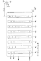
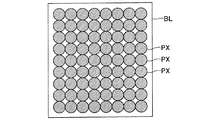
図5は、一色のインクにより印刷形成された検査用パターンの一例を模式的に示す説明図であり、図6は、検査用パターンを構成する検査用印刷ブロックBLを模式的に示す説明図である。 FIG. 5 is an explanatory view schematically showing an example of an inspection pattern printed and formed with one color ink, and FIG. 6 is an explanatory view schematically showing an inspection print block BL constituting the inspection pattern. is there.
インク吐出検査に際しては、先ず、検査用パターンを作成する。この検査用パターンは、各色のインクを吐出するノズル列によりインク色ごとにそれぞれ印刷形成される検査用パターンである。即ち、総てのノズルのインク吐出状態を検査する場合には、印刷ヘッド36が有するノズル列から吐出されるインクの色数分の検査用パターンが形成される。
In the ink ejection inspection, first, an inspection pattern is created. This test pattern is a test pattern that is printed and formed for each ink color by a nozzle row that ejects ink of each color. That is, when inspecting the ink ejection states of all the nozzles, inspection patterns corresponding to the number of colors of ink ejected from the nozzle rows of the
従って、本実施の形態においては、八つの検査用パターンが作成されることになる。また、一色のノズル列にN個のノズルが配列されていて、それらN個のノズルの検査を行う場合の検査用パターンには、N個の印刷ブロックBLが印刷されることになる。 Therefore, in this embodiment, eight inspection patterns are created. Further, N print blocks BL are printed in an inspection pattern when N nozzles are arranged in a single color nozzle row and the N nozzles are inspected.
検査用パターンは、各ノズルから吐出されるインクによりノズルごとにそれぞれ形成される複数の検査用印刷ブロックBLにより構成され、一つの印刷ブロックBLは、図6に示すように、複数のインクドットPXにより形成される。 The test pattern is composed of a plurality of test print blocks BL formed for each nozzle by the ink ejected from each nozzle, and one print block BL includes a plurality of ink dots PX as shown in FIG. It is formed by.
一つの印刷用検査ブロックBLは一つのノズルから吐出されるインクのみによって印刷形成されるので、一つの印刷用検査ブロックBLはそれに対応する一つのノズルの検査に用いられる。図5は、54個のノズルを有するノズル列により形成される検査用パターンを示している。 Since one printing inspection block BL is formed by printing only with ink ejected from one nozzle, one printing inspection block BL is used for inspection of one nozzle corresponding thereto. FIG. 5 shows an inspection pattern formed by a nozzle row having 54 nozzles.
この検査用パターンは、主走査方向(左右方向)に9個、副走査方向に6個の検査用印刷ブロックBLが配置されて構成されている。即ち、主走査方向に配列された9個の検査用印刷ブロックにより構成される検査用印刷ブロックアレイが、副走査方向に6段形成されている。 This inspection pattern is configured by nine inspection print blocks BL arranged in the main scanning direction (left-right direction) and six in the sub-scanning direction. That is, six inspection print block arrays each including nine inspection print blocks arranged in the main scanning direction are formed in the sub-scanning direction.
搬送方向の最も下流側に位置する1段目の検査用印刷ブロックアレイは、9番ノズル#9から1番ノズル#1までにより印刷され、2段目の検査用印刷ブロックアレイは、18番ノズル#18から10番ノズル#10までにより印刷され、以下同様に、6段目の検査用印刷ブロックアレイは54番ノズル#54から46番ノズル#46までにより印刷される。
The first-stage inspection print block array located on the most downstream side in the transport direction is printed by the
検査用パターンを構成する各検査用印刷ブロックアレイの印刷に際しては、所定の位置に位置決めされた印刷用紙に対し、例えばキャリッジ28を図5における左側から右側へ走査しつつ、54番、45番、36番、27番、18番、9番ノズル#54、#45、#36、#27、#18、#9からインクを吐出して所定数のドットを形成し、検査用印刷ブロックBLの主走査方向の幅の分だけ印刷する。キャリッジ28は走査を継続しつつ、53番、44番、35番、26番、17番、8番ノズル#53、#44、#35、#26、#17、#8からインクを吐出して、第2列の検査用印刷ブロックを形成するための所定数のドットによりドット列又はラインを形成する。
When printing each inspection printing block array constituting the inspection pattern, for example, the
このように、ノズル列を構成する各ノズルは、検査用パターンの主走査方向に配置される検査用印刷ブロック数に等しい数ごとのノズルを順にそれぞれグループ化してサブノズルグループとされ、各サブノズルグループの副走査方向において同一の順番に位置するノズルごとにインクを吐出して各検査用印刷ブロックを形成していく。 As described above, each nozzle constituting the nozzle row is grouped into nozzles corresponding to the number of test print blocks arranged in the main scanning direction of the test pattern in order to form sub nozzle groups. Each inspection print block is formed by ejecting ink for each nozzle located in the same order in the sub-scanning direction.
図5における左側から右側へのキャリッジ28による走査が終了すると、印刷用紙を副走査方向にノズルピッチ分だけ搬送する。その後、右側から左側へキャリッジ28による走査を行い、直前の走査と逆の順序で所定のノズルからインクを吐出してドット列又はラインを形成する。
When the scanning by the
このように、印刷用紙を副走査方向にノズルピッチ分だけ搬送する動作と、各サブノズルグループの副走査方向における同一の順番に位置するノズルごとにインクを吐出しながら主走査方向における走査を行う動作とを繰り返し、9本のドット列又はラインを形成すると検査用印刷ブロックが形成される。総てのノズルから正常にインクが吐出されると、最終的に54個の検査用印刷ブロックを有する検査用パターンが印刷される。 As described above, an operation for transporting printing paper by the nozzle pitch in the sub-scanning direction, and an operation for performing scanning in the main scanning direction while ejecting ink for each nozzle located in the same order in the sub-scanning direction of each sub-nozzle group. When nine dot rows or lines are formed, an inspection print block is formed. When ink is normally ejected from all the nozzles, an inspection pattern having 54 inspection print blocks is finally printed.
尚、図5からも分かるように、主走査方向(左右方向)において相互に隣接する検査用印刷ブロック、例えば、54番ノズル#54により形成された検査用印刷ブロックと、53番ノズル#53により形成された検査用印刷ブロックとは、副走査方向にノズルピッチ分だけずれた位置に印刷される。
As can be seen from FIG. 5, the inspection print blocks adjacent to each other in the main scanning direction (left-right direction), for example, the inspection print block formed by the
各検査用印刷ブロックを形成するドットは、相互に隣接する検査用印刷ブロック間においても等間隔に形成され、各検査用印刷ブロック間には余白部分は生じない。 The dots forming each test print block are formed at equal intervals between the test print blocks adjacent to each other, and no blank portion is generated between the test print blocks.
本実施の形態では、キャリッジ28の各走査の間に実行される印刷用紙の搬送における搬送量をノズルピッチ分としたが、当該搬送量は任意であり、例えば搬送量をノズルピッチの半分とすると、各検査用印刷ブロックを構成するドットの数が多くなり、各検査用印刷ブロックの濃度は高くなる。このとき、各検査用印刷ブロックを構成するドット列又はラインの数は18本となる。
In the present embodiment, the conveyance amount in the conveyance of the printing paper executed during each scan of the
図7は、光センサによる走査の際の検査用パターン上におけるスポットの軌跡を模式的に示す説明図である。尚、図5の説明において前述したように、主走査方向において相互に隣接する検査用印刷ブロックは、厳密には、副走査方向にノズルピッチ分だけずれた位置に印刷されるのであるが、図7においては簡略化のため、各検査用印刷ブロックがずれのないマトリクス状に配置形成された状態の検査用パターン71を示している。
FIG. 7 is an explanatory diagram schematically showing the locus of spots on the inspection pattern during scanning by the optical sensor. As described above with reference to FIG. 5, the inspection print blocks adjacent to each other in the main scanning direction are printed at positions shifted by the nozzle pitch in the sub-scanning direction. In FIG. 7, for simplification, an
インク吐出の有無の判定に際しては、キャリッジ28(図1)に取り付けられた光センサ41と印刷用紙Pとを相対的に移動させ、検査用印刷ブロックBL上を光センサ41により走査する。
When determining the presence or absence of ink ejection, the
このとき、光センサ41の発光部41aからの照射光La(図4)のスポットを、図7の軌跡XYのように各検査用印刷ブロックBLに順次当てていき、検査用印刷ブロックBLからの反射光Lbを受光部41bにより検出し、検出した反射光Lbの強度に応じて受光部41bから出力された電気信号のレベルを所定の閾値と比較することによりインク吐出の有無を判定する。出力信号レベルと所定の閾値との比較は、各検査用印刷ブロックBLごとに行う。
At this time, the spot of the irradiation light La (FIG. 4) from the
尚、図2に示すように、本実施の形態においては、光センサ41は、印刷ヘッド36が有する総てのノズルより下流側に配置されているので、下流側の一部の印刷ブロックBLについては、上流側の一部の印刷ブロックBLを印刷する際のキャリッジ28の移動動作において光センサ41による走査を行い、同時にインク吐出の有無を判定する。
As shown in FIG. 2, in the present embodiment, the
また、光センサ41の発光部41aからの照射光により印刷用紙が照射される領域は、印刷用紙上において円形のスポットとなるが、本実施の形態においては、スポット内に検査用印刷ブロックBLが1個含まれるようにスポットが設定されている。
Further, the area irradiated with the printing paper by the light emitted from the
図8は、インク吐出の有無の判定における出力信号レベルと判定閾値との関係を示すグラフである。 FIG. 8 is a graph showing the relationship between the output signal level and the determination threshold in determining whether or not ink is ejected.
目詰まりによりインクが吐出されないノズルが存在する場合、印刷用紙上に形成される検査用印刷ブロックBLのうち当該ノズルに対応する印刷ブロックは、インクが滴下されない空白印刷ブロックBLaとなる。 When there is a nozzle from which ink is not ejected due to clogging, the printing block corresponding to the nozzle among the inspection printing blocks BL formed on the printing paper is a blank printing block BLa in which ink is not dropped.
光センサ41の発光部41aから出射された照射光のスポットにより照射される印刷ブロックが空白印刷ブロックBLaである場合は、光センサ41の受光部41bが検出する反射光Lbの強度が増加するので、検出した反射光Lbの強度に応じて変換される出力信号レベルは上昇する。
When the printing block irradiated by the spot of the irradiation light emitted from the
一方、スポットにより照射される印刷ブロックが正常に印刷された正常印刷ブロックBLbである場合は、受光部41bが検出する反射光Lbの強度が減少するので、検出した反射光Lbの強度に応じて変換される出力信号レベルは低下する。
On the other hand, when the printing block irradiated by the spot is a normal printing block BLb printed normally, the intensity of the reflected light Lb detected by the
即ち、発光部41aにより形成されたスポットが空白印刷ブロックBLaを走査した際の出力信号レベルVLは相対的に高い値となり、スポットが正常印刷ブロックBLbを走査した際の出力信号レベルV0は相対的に低い値となる。
That is, the output signal level VL when the spot formed by the
従って、図8に示すように、空白印刷ブロックBLaに対応する出力信号レベルVLと正常印刷ブロックBLbに対応する出力信号レベルV0との間に、判定閾値Vthを設定しておくことにより、出力信号レベルと判定閾値Vthとを比較して、各ノズルにおけるインク吐出の有無を判定することができる。 Therefore, as shown in FIG. 8, by setting the determination threshold Vth between the output signal level VL corresponding to the blank print block BLa and the output signal level V0 corresponding to the normal print block BLb, the output signal By comparing the level with the determination threshold value Vth, it is possible to determine whether or not ink is ejected from each nozzle.
以上のようなインク吐出の有無の判定を行う際におけるハードウェアの動作は、以下の通りである。 The hardware operation when determining whether or not to discharge ink as described above is as follows.
システムコントローラ54(図3)の判定部54aは、インク吐出の有無を判定するために、光センサ41からの出力信号レベルと、予め設定されメインメモリ56に記憶された判定閾値Vthとを比較する。
The
出力信号レベルが閾値Vthより小さい場合、スポットに含まれている印刷ブロックは正常に印刷された正常印刷ブロックであり、当該印刷ブロックの印刷に用いられたノズルからはインクが正常に吐出されていると判定する。逆に、出力信号レベルが閾値Vthより大きい場合、スポットに含まれている印刷ブロックはインクが滴下されなかった空白印刷ブロックであり、当該印刷ブロックの印刷に用いられたノズルからはインクが正常に吐出されていないと判定する。 When the output signal level is smaller than the threshold value Vth, the print block included in the spot is a normal print block printed normally, and ink is normally ejected from the nozzle used for printing the print block. Is determined. On the other hand, when the output signal level is larger than the threshold value Vth, the printing block included in the spot is a blank printing block in which ink has not been dropped, and ink is normally discharged from the nozzle used for printing the printing block. It is determined that the ink is not discharged.
プリンタ20は、発光部41aからの照射光により印刷用紙が照射される領域、即ち、スポット内に一つの印刷ブロックが含まれる構成とすると共に、リニアエンコーダ29の出力とロータリーエンコーダ25の出力とにより、キャリッジ28と印刷用紙との相対位置を認識可能とし、さらに、総てのノズルより搬送方向の下流側に設けた光センサ41と各ノズルとの相対位置が予め正確に調整され且つ認識されているものとする。
The
従って、インク吐出の有無を判定するために、キャリッジ28の走査動作によって、光センサ41による検査用印刷ブロックの走査を行った結果、インクが滴下されなかった空白印刷ブロックが検出された場合には、リニアエンコーダ29及びロータリーエンコーダ25の出力に基づいて、当該空白印刷ブロックに対応するノズルを、インク吐出が正常に行われない異常ノズルとして特定することが可能である。
Therefore, when a blank print block in which ink has not been dropped is detected as a result of scanning the inspection print block by the
インク吐出が正常に行われない異常ノズルが特定されたときは、当該異常ノズルのみに対しフラッシング等を実行して良好な状態に回復させたり、あるいは、当該異常ノズルが本来形成すべきドットを他のノズルを用いて形成させて印刷することも可能である。 When an abnormal nozzle that does not eject ink normally is identified, flushing or the like is performed only on the abnormal nozzle to restore it to a good state, or other dots that should be originally formed by the abnormal nozzle It is also possible to form and print using this nozzle.
図9は、光学式センサの受光出力信号波形と判定閾値との関係を示すグラフである。 FIG. 9 is a graph showing the relationship between the light reception output signal waveform of the optical sensor and the determination threshold.
上述のように、光学式センサのスポットにより照射される印刷ブロックが正常に印刷された正常印刷ブロックBLbである場合は、受光部41bが検出する反射光Lbの強度が減少するので、検出した反射光Lbの強度に応じて変換される出力信号レベルは低下する。従って、スポットが正常印刷ブロックBLbを走査した際の出力信号レベルV0は相対的に低い値となり、この出力信号レベルV0を基準レベルとして受光出力信号波形は変動することとなる。
As described above, when the printing block irradiated by the spot of the optical sensor is a normal printing block BLb printed normally, the intensity of the reflected light Lb detected by the
一方、光学式センサのスポットにより照射される印刷ブロックが空白印刷ブロックBLaである場合は、光センサ41の受光部41bが検出する反射光Lbの強度が増加するので、検出した反射光Lbの強度に応じて変換される出力信号レベルは上昇する。従って、発光部41aにより形成されたスポットが空白印刷ブロックBLaを走査した際の出力信号レベルVLは相対的に高い値となり、図9に示すような受光出力信号波形においては、極大値VLのピークとして観測される。
On the other hand, when the printing block irradiated by the spot of the optical sensor is the blank printing block BLa, the intensity of the reflected light Lb detected by the
それ故に、通常は、基準レベルとなる出力信号レベルV0とピークレベルとなる出力信号レベルVLとの間に、判定閾値Vthを設定しておくことにより、センサ受光出力信号レベルと判定閾値Vthとを比較して、各ノズルにおけるインク吐出の有無を判定することができる。 Therefore, normally, by setting the determination threshold Vth between the output signal level V0 serving as the reference level and the output signal level VL serving as the peak level, the sensor light reception output signal level and the determination threshold Vth are set. In comparison, the presence or absence of ink ejection at each nozzle can be determined.
さて、前述のように、光学式センサは、インク吐出判定用光学式センサとしての用途に限らず、Bi−D調整のための印刷パターン検出等、反射光の強度に反映される印刷媒体表面の印刷状態又は印刷媒体の有無の検出による印刷装置の種々の動作状態の判定を行う印刷動作状態判定装置として広く使用することができる。 As described above, the optical sensor is not limited to the use as an optical sensor for ink ejection determination, but is used for detecting the print pattern for Bi-D adjustment, etc. The present invention can be widely used as a printing operation state determination device that determines various operation states of a printing apparatus by detecting the printing state or the presence or absence of a printing medium.
ここで、Bi−D印刷の往路インク滴下位置と復路インク滴下位置との相対位置調整状態の判定を、光学式センサによる印刷パターンの印刷濃度検出を通じて行う方法について説明する。 Here, a method for determining the relative position adjustment state between the forward ink drop position and the return ink drop position of Bi-D printing through detection of the print density of the print pattern by an optical sensor will be described.
双方向(Bi−D)印刷とは、印刷ヘッドを搭載したキャリッジの主走査方向駆動動作における往路駆動動作及び復路駆動動作の双方において印刷ヘッドのノズルからインクを吐出して印刷を行う印刷方式であり、印刷効率の向上、印刷画像の高画質化等の観点から採用されている技術である。 Bi-directional (Bi-D) printing is a printing method in which printing is performed by ejecting ink from the nozzles of the print head in both the forward drive operation and the backward drive operation in the main scanning direction drive operation of the carriage on which the print head is mounted. This technique is employed from the viewpoints of improving printing efficiency and improving the quality of printed images.
このBi−D印刷では、往路駆動動作及び復路駆動動作の双方において印刷媒体に対しインク滴下を行うので、印刷画像の高画質化のためには、往路インク滴下位置と復路インク滴下位置との相対位置が正確に調整されていなければならない。 In this Bi-D printing, ink is dropped on the print medium in both the forward drive operation and the backward drive operation. Therefore, in order to improve the quality of the printed image, the relative relationship between the forward ink drop position and the backward ink drop position is determined. The position must be adjusted accurately.
そこで、Bi−D調整用印刷ブロックパターンをBi−D印刷により形成し、各印刷ブロックパターンの印刷濃度を光学式センサを用いて検出することにより、Bi−D印刷の往路インク滴下位置と復路インク滴下位置との相対位置調整状態の判定を行い、その判定結果に基づいてBi−D印刷設定を行う。 Therefore, a Bi-D adjustment printing block pattern is formed by Bi-D printing, and the print density of each printing block pattern is detected using an optical sensor, whereby the forward ink drop position and the return ink of Bi-D printing are detected. The relative position adjustment state with respect to the dropping position is determined, and Bi-D print setting is performed based on the determination result.
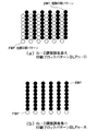
図10は、Bi−D調整用印刷ブロックパターンの一例を示す平面図である。 FIG. 10 is a plan view showing an example of a printing block pattern for Bi-D adjustment.
Bi−D調整用印刷ブロックパターンは、図10に示すように、往路印刷パターンFWPと復路印刷パターンBWPとから構成される。往路印刷パターンFWP及び復路印刷パターンBWPはいずれも主走査方向、即ち、印刷ヘッドを搭載したキャリッジの駆動方向に直交する縦ライン状印刷パターンである。 As shown in FIG. 10, the Bi-D adjustment printing block pattern is composed of a forward printing pattern FWP and a backward printing pattern BWP. The forward print pattern FWP and the backward print pattern BWP are both vertical line-shaped print patterns orthogonal to the main scanning direction, that is, the drive direction of the carriage on which the print head is mounted.
Bi−D印刷設定においては、各Bi−D調整用印刷ブロックパターン形成領域上を印刷ヘッドが通過する際に、往路駆動動作中は一様な吐出タイミングでインクをノズルから吐出して滴下して往路印刷パターンFWPを各Bi−D調整用印刷ブロックパターン形成領域に印刷し、復路駆動動作中は各Bi−D調整用印刷ブロックパターンごとに少しずつ吐出タイミングをずらしながらインクをノズルから吐出して滴下して往路印刷パターンFWPを各Bi−D調整用印刷ブロックパターン形成領域の往路印刷パターンFWPに重ねて印刷することにより、往路印刷パターンFWPと復路印刷パターンBWPとの相対位置、即ち、往路インク滴下位置と復路インク滴下位置との相対位置が少しずつ異なる複数のBi−D調整用印刷ブロックパターンを印刷形成する。 In the Bi-D print setting, when the print head passes over each Bi-D adjustment print block pattern formation region, ink is ejected from the nozzles and dropped at a uniform ejection timing during the forward drive operation. The forward printing pattern FWP is printed on each Bi-D adjustment printing block pattern formation area, and the ink is ejected from the nozzles while shifting the ejection timing little by little for each Bi-D adjustment printing block pattern during the backward driving operation. By dropping and printing the forward print pattern FWP on the forward print pattern FWP in each Bi-D adjustment printing block pattern forming area, the relative position of the forward print pattern FWP and the backward print pattern BWP, that is, the forward ink, is printed. A plurality of Bi-D adjustment printing block patterns in which the relative positions of the dropping position and the return ink dropping position are slightly different. The over down to print form.
このBi−D調整用印刷ブロックパターンにおいて、往路印刷パターンFWPを構成する縦ライン状印刷パターンと復路印刷パターンBWPを構成する縦ライン状印刷パターンとが、図10(a)に示すように、交互に印刷されている場合は、当該Bi−D調整用印刷ブロックパターンBLPn−Dを印刷した際のインク吐出タイミングの誤差が最大になっているということを意味する。 In this Bi-D adjustment printing block pattern, as shown in FIG. 10A, the vertical line-shaped printing pattern constituting the forward path printing pattern FWP and the vertical line-shaped printing pattern constituting the backward path printing pattern BWP are alternately arranged. Is printed, it means that the error of the ink ejection timing when the Bi-D adjustment printing block pattern BLPn-D is printed is maximized.
尚、インク吐出タイミングの誤差が最大になっている図10(a)に示すようなBi−D調整用印刷ブロックパターンBLPn−Dは、余白部分が非常に少ないので、Bi−D調整において印刷される一連のBi−D調整用印刷ブロックパターン群のなかでは最も印刷濃度が高くなる。 Note that the printing block pattern BLPn-D for Bi-D adjustment as shown in FIG. 10A in which the error of the ink ejection timing is maximum has a very small margin, and is printed in Bi-D adjustment. Among the series of print block patterns for Bi-D adjustment, the print density is the highest.
一方、Bi−D調整用印刷ブロックパターンにおいて、往路印刷パターンFWPを構成する縦ライン状印刷パターンと復路印刷パターンBWPを構成する縦ライン状印刷パターンとが、図10(b)に示すように、ちょうど重なり合って印刷されている場合は、当該Bi−D調整用印刷ブロックパターンBLPn−Aを印刷した際のインク吐出タイミングの誤差が最小になっており、当該印刷装置における最適なBi−D印刷設定であるということになる。 On the other hand, in the print block pattern for Bi-D adjustment, as shown in FIG. 10B, the vertical line-shaped print pattern constituting the forward path print pattern FWP and the vertical line-shaped print pattern constituting the backward path print pattern BWP are as shown in FIG. When printing is performed in an overlapping manner, an error in ink ejection timing when the Bi-D adjustment printing block pattern BLPn-A is printed is minimized, and the optimum Bi-D printing setting in the printing apparatus is performed. It means that.
従って、当該Bi−D調整用印刷ブロックパターンBLPn−Aを印刷した際のインク吐出タイミングを当該印刷装置のBi−D印刷設定として採用すれば、当該印刷装置によるBi−D印刷において高画質を実現することができる。 Therefore, if the ink ejection timing when the Bi-D adjustment printing block pattern BLPn-A is printed is adopted as the Bi-D print setting of the printing apparatus, high image quality is realized in Bi-D printing by the printing apparatus. can do.
尚、インク吐出タイミングの誤差が最小になっている図10(b)に示すようなBi−D調整用印刷ブロックパターンBLPn−Aは、余白部分が非常に多いので、Bi−D調整において印刷される一連のBi−D調整用印刷ブロックパターン群のなかでは最も印刷濃度が低くなる。 Note that the printing block pattern BLPn-A for Bi-D adjustment as shown in FIG. 10B in which the error of the ink ejection timing is minimized has a very large margin, and is printed in the Bi-D adjustment. In the series of Bi-D adjustment printing block pattern groups, the print density is the lowest.
図11は、Bi−D調整において印刷される一連のBi−D調整用印刷ブロックパターン群の一例を示す平面図である。 FIG. 11 is a plan view showing an example of a series of print block patterns for Bi-D adjustment printed in Bi-D adjustment.
Bi−D調整のためのBi−D印刷設定においては、上述のように、各Bi−D調整用印刷ブロックパターン形成領域上を印刷ヘッドが通過する際に、往路駆動動作中は一様な吐出タイミングでインクをノズルから吐出して滴下し、復路駆動動作中は各Bi−D調整用印刷ブロックパターンごとに少しずつ吐出タイミングをずらしながらインクをノズルから吐出して滴下して、各Bi−D調整用印刷ブロックパターンを印刷形成する。 In the Bi-D print setting for Bi-D adjustment, as described above, when the print head passes over each Bi-D adjustment print block pattern formation region, uniform ejection is performed during the forward drive operation. Ink is ejected and dropped from the nozzle at the timing, and during the backward drive operation, the ink is ejected and dropped from the nozzle while slightly shifting the ejection timing for each Bi-D adjustment printing block pattern. A printing block pattern for adjustment is formed by printing.
従って、一連のBi−D調整用印刷ブロックパターン群は、図11に示すように、各Bi−D調整用印刷ブロックパターンごとに段階的かつ周期的に印刷濃度が変化するものとなる。 Therefore, as shown in FIG. 11, a series of Bi-D adjustment printing block pattern groups has a print density that changes stepwise and periodically for each Bi-D adjustment printing block pattern.
図11においては、一例として、13個のBi−D調整用印刷ブロックパターンBLP1,BLP2,...,BLP13が4段階の印刷濃度A,B,C,D(A<B<C<D)に印刷されているものとし、各符号に当該印刷ブロックパターンの印刷濃度を示す符号−A,−B,−C,−Dを付記して示している。印刷濃度が周期的に変化しているので、付記される符号もA,B,C,D,C,B,A,...という順に並んでいる。 In FIG. 11, as an example, thirteen Bi-D adjustment printing block patterns BLP1, BLP2,. . . , BLP13 are printed at four levels of print densities A, B, C, D (A <B <C <D), and symbols -A, -B indicating the print density of the print block pattern for each symbol. , -C, -D are shown. Since the print density changes periodically, the symbols added are also A, B, C, D, C, B, A,. . . It is arranged in the order.
Bi−D調整において印刷される一連のBi−D調整用印刷ブロックパターン群は、図11に示すように、通常、最高印刷濃度Dの2個のBi−D調整用印刷ブロックパターンBLP4−D,BLP10−Dの中間位置に最低印刷濃度AのBi−D調整用印刷ブロックパターンBLP7−Aが印刷される形態となる。 As shown in FIG. 11, a series of Bi-D adjustment printing block pattern groups printed in Bi-D adjustment usually includes two Bi-D adjustment printing block patterns BLP4-D having the highest printing density D. A printing block pattern BLP7-A for Bi-D adjustment having a minimum printing density A is printed at an intermediate position of BLP10-D.
そして、このBi−D調整用印刷ブロックパターンBLP7−Aを印刷した際のインク吐出タイミングが、当該印刷装置における最適なBi−D印刷設定であるということになる。従って、Bi−D調整用印刷ブロックパターンBLP7−Aを印刷した際のインク吐出タイミングを当該印刷装置のBi−D印刷設定として採用することにより、当該印刷装置によるBi−D印刷において高画質を実現することができる。 The ink ejection timing when the Bi-D adjustment printing block pattern BLP7-A is printed is the optimum Bi-D print setting in the printing apparatus. Therefore, by adopting the ink ejection timing when the printing block pattern BLP7-A for Bi-D adjustment is printed as the Bi-D printing setting of the printing device, high image quality is realized in Bi-D printing by the printing device. can do.
尚、図11に示すように、一連のBi−D調整用印刷ブロックパターン群においては、最高印刷濃度Dの2個のBi−D調整用印刷ブロックパターンBLP4−D,BLP10−Dの外側にも、2個の最低印刷濃度AのBi−D調整用印刷ブロックパターンBLP1−A,BLP13−Aが現れる場合が多い。 As shown in FIG. 11, in the series of Bi-D adjustment printing block pattern groups, the two Bi-D adjustment printing block patterns BLP4-D and BLP10-D having the highest printing density D are also provided outside. In many cases, two Bi-D adjustment printing block patterns BLP1-A and BLP13-A having the lowest printing density A appear.
しかし、これら両端の最低印刷濃度AのBi−D調整用印刷ブロックパターンは、図10(b)に示す往路印刷パターンFWPを構成する縦ライン状印刷パターンと復路印刷パターンBWPを構成する縦ライン状印刷パターンとがちょうど一列分だけずれて重なり合って印刷されたことにより、見かけ上、中央のBi−D調整用印刷ブロックパターンBLP7−Aと同様の最低印刷濃度Aとなっているものである。 However, the Bi-D adjustment printing block pattern having the minimum printing density A at both ends is a vertical line-shaped printing pattern constituting the forward printing pattern FWP and a vertical printing pattern BWP constituting the backward printing pattern BWP shown in FIG. Since the print pattern is printed by being shifted by exactly one line and overlapping, the minimum print density A is apparently the same as the central Bi-D adjustment print block pattern BLP7-A.
従って、これら両端の最低印刷濃度AのBi−D調整用印刷ブロックパターンを印刷した際のインク吐出タイミングは、通常、当該印刷装置におけるBi−D印刷設定として採用しない。 Therefore, the ink ejection timing when printing the Bi-D adjustment printing block pattern having the minimum printing density A at both ends is not usually adopted as the Bi-D printing setting in the printing apparatus.
以上のようなBi−D調整のための印刷パターン検出の他にも、光学式センサは、反射光の強度に反映される印刷媒体表面の印刷状態又は印刷媒体の有無の検出による印刷装置の種々の動作状態の判定を行う印刷動作状態判定装置として広く使用することができ、例えば、紙送り誤差検出装置としても使用することができる。 In addition to the print pattern detection for Bi-D adjustment as described above, the optical sensor is used in various printing apparatuses based on the detection of the print state of the print medium surface or the presence or absence of the print medium reflected in the intensity of reflected light. It can be widely used as a printing operation state determination device that determines the operation state of, for example, and can also be used as a paper feed error detection device.
そこで、光学式センサを紙送り誤差検出装置として使用する場合における紙送り誤差検出方法について説明する。 Therefore, a paper feed error detection method when an optical sensor is used as a paper feed error detection device will be described.
図12は、光学式センサを紙送り誤差検出装置として使用する紙送り誤差検出方法において印刷する紙送り誤差検出用印刷パターンの構成を模式的に示す平面図である。 FIG. 12 is a plan view schematically showing the configuration of a paper feed error detection print pattern printed in a paper feed error detection method using an optical sensor as a paper feed error detection device.
光学式センサを紙送り誤差検出装置として使用する紙送り誤差検出方法においては、先ず、印刷ヘッドに形成された複数のインク吐出部の一部により構成される上流側ノズル列によりライン状の基準パターンR(N)を印刷した後、その上流側ノズル列の直下に位置していた印刷媒体領域が、印刷媒体搬送方向において上流側ノズル列よりも下流側に位置する複数のインク吐出部の一部により構成される下流側ノズル列の直下に位置することとなる紙送り量の理論値に補正値を適宜加算しながら紙送り動作を実行する。 In a paper feed error detection method using an optical sensor as a paper feed error detection device, first, a linear reference pattern is formed by an upstream nozzle row composed of a part of a plurality of ink ejection portions formed on a print head. After printing R (N), a part of the plurality of ink ejection units in which the print medium region located immediately below the upstream nozzle row is located downstream of the upstream nozzle row in the print medium conveyance direction The paper feed operation is executed while appropriately adding a correction value to the theoretical value of the paper feed amount that is positioned immediately below the downstream nozzle row configured by the above.
ここで、紙送り量の理論値とは、紙送りローラが偏心又は偏摩耗等の生じていない設計データ通りの寸法のものであると仮定した場合において、印刷しようとする画像データから算出された紙送り量の値をいう。 Here, the theoretical value of the paper feed amount is calculated from the image data to be printed when it is assumed that the paper feed roller has a dimension as designed data with no eccentricity or uneven wear. This is the value of the paper feed amount.
そして、基準パターンR(N)と同様のライン状の調整用パターンA(N)を上端部ノズル列36Aにより基準パターンR(N)に重ねて印刷する。 Then, a linear adjustment pattern A (N) similar to the reference pattern R (N) is printed over the reference pattern R (N) by the upper end nozzle row 36A.
尚、この紙送り誤差検出用印刷パターンを構成する基準パターンR(N)及び調整用パターンA(N)は、紙送り誤差を検出するためのものであるから、印刷媒体の搬送方向としての副走査方向に直交する主走査方向に平行な横ライン状印刷パターンである。紙送り誤差検出用印刷パターンは、この点において、キャリッジの駆動方向としての主走査方向に直交する副走査方向に平行な縦ライン状印刷パターンである往路印刷パターンFWP及び復路印刷パターンBWPにより構成されるBi−D調整用印刷ブロックパターンと異なっている。 The reference pattern R (N) and the adjustment pattern A (N) that constitute the paper feed error detection print pattern are for detecting a paper feed error. It is a horizontal line-shaped print pattern parallel to the main scanning direction orthogonal to the scanning direction. In this respect, the paper feed error detection print pattern is composed of a forward print pattern FWP and a reverse print pattern BWP which are vertical line-shaped print patterns parallel to the sub-scanning direction orthogonal to the main scanning direction as the carriage driving direction. This is different from the Bi-D adjustment printing block pattern.
紙送り誤差が最小限に抑制されている場合、即ち、紙送り量に全く誤差が生じていない場合には、図10(b)に示すように、基準パターンR(N)と調整用パターンA(N)とはちょうど重なり合って印刷され、基準パターンR(N)及び調整用パターンA(N)からなる紙送り誤差検出用印刷パターンの印刷濃度は最小となる。 When the paper feed error is suppressed to the minimum, that is, when there is no error in the paper feed amount, as shown in FIG. 10B, the reference pattern R (N) and the adjustment pattern A (N) is printed so as to overlap, and the print density of the paper feed error detection print pattern composed of the reference pattern R (N) and the adjustment pattern A (N) is minimized.
一方、ノズルピッチの範囲内で最大限の紙送り誤差が生じている場合、即ち、ノズルピッチの1/2だけ紙送り誤差が生じている場合には、図10(a)に示すように、基準パターンR(N)を構成するラインと調整用パターンA(N)を構成するラインとが交互に印刷され、基準パターンR(N)及び調整用パターンA(N)からなる紙送り誤差検出用印刷パターンの印刷濃度は最大となる。 On the other hand, when the maximum paper feed error occurs within the nozzle pitch range, that is, when the paper feed error is generated by ½ of the nozzle pitch, as shown in FIG. For detecting a paper feed error, a line constituting the reference pattern R (N) and a line constituting the adjustment pattern A (N) are alternately printed, and the reference pattern R (N) and the adjustment pattern A (N) are included. The print pattern has the maximum print density.
光学式センサを紙送り誤差検出装置として使用する紙送り誤差検出方法では、上述のようなライン状の基準パターンR(N)及び調整用パターンA(N)からなる紙送り誤差検出用印刷パターンの印刷濃度を検出することにより実際に発生している紙送り誤差を検出し、紙送り動作を実行する際に紙送り量の理論値に加算すべき補正値を決定する。 In a paper feed error detection method using an optical sensor as a paper feed error detection device, a paper feed error detection print pattern composed of a linear reference pattern R (N) and an adjustment pattern A (N) as described above is used. By detecting the print density, a paper feed error actually generated is detected, and a correction value to be added to the theoretical value of the paper feed amount when the paper feed operation is executed is determined.
具体的には、紙送り量の理論値に加算する補正値をノズルピッチの±1/2の範囲で変動させながら、紙送り動作の前に基準パターンR(N)を、紙送り動作の後に調整用パターンA(N)をそれぞれ印刷し、各補正値に対応する紙送り誤差検出用印刷パターンの印刷濃度を検出して、最も印刷濃度の低い紙送り誤差検出用印刷パターンを特定することにより、紙送り量の理論値に加算すべき補正値の最適値を決定する。 Specifically, while changing the correction value to be added to the theoretical value of the paper feed amount within a range of ± 1/2 of the nozzle pitch, the reference pattern R (N) is changed after the paper feed operation. By respectively printing the adjustment pattern A (N), detecting the print density of the paper feed error detection print pattern corresponding to each correction value, and specifying the paper feed error detection print pattern with the lowest print density The optimum correction value to be added to the theoretical value of the paper feed amount is determined.
補正値を±1/2ノズルピッチの範囲、即ち、1ノズルピッチの範囲で変動させることとしているのは、その範囲で補正値を変動させれば、必ずいずれかの値の補正値を用いたときに、基準パターンR(N)と調整用パターンA(N)とがちょうど重なり合って印刷されるはずだからである。 The reason for changing the correction value within the range of ± 1/2 nozzle pitch, that is, the range of one nozzle pitch, is that any correction value is always used if the correction value is changed within that range. This is because the reference pattern R (N) and the adjustment pattern A (N) should be printed so as to overlap each other.
上述のようなBi−D調整により最適なBi−D印刷設定を行ったり、紙送り誤差検出により紙送り誤差の補正を行って高画質を実現するためには、前提条件として、一連のBi−D調整用印刷ブロックパターン群を構成する各Bi−D調整用印刷ブロックパターンの印刷濃度、及び、一連の紙送り誤差検出用印刷パターン群を構成する各紙送り誤差検出用印刷パターンの印刷濃度を正確に検出することが必要とされる。 In order to realize the high image quality by performing the optimal Bi-D print setting by the Bi-D adjustment as described above or correcting the paper feed error by detecting the paper feed error, a series of Bi-D is used as a precondition. The print density of each Bi-D adjustment print block pattern constituting the D adjustment print block pattern group and the print density of each paper feed error detection print pattern constituting the series of paper feed error detection print pattern groups are accurately determined. To be detected.
しかしながら、光学式センサには、検出距離、即ち、発光部と印刷媒体表面との距離及び印刷媒体表面と受光部との距離が変動すると、印刷媒体表面の印刷状態が一様であっても受光出力信号レベルが変動するという特性がある。 However, when the detection distance, that is, the distance between the light emitting part and the print medium surface and the distance between the print medium surface and the light receiving part are fluctuated, the optical sensor receives light even if the printing state of the print medium surface is uniform. There is a characteristic that the output signal level fluctuates.
図13は、光学式センサの検出距離変動に対する受光出力特性を示すグラフである。尚、図13のグラフの横軸では、検出距離が小さくなる方向を−、検出距離が大きくなる方向を+としている。 FIG. 13 is a graph showing the light reception output characteristic with respect to the detection distance variation of the optical sensor. In the horizontal axis of the graph of FIG. 13, the direction in which the detection distance decreases is −, and the direction in which the detection distance increases is +.
図13のグラフに示されるように、光学式センサにおいては、検出距離が最適値に設定されているときに最も大きくかつ安定した受光出力信号が得られる。 As shown in the graph of FIG. 13, in the optical sensor, the largest and stable light reception output signal is obtained when the detection distance is set to the optimum value.
しかし、検出距離が最適値より小さくなったり大きくなったりすると、得られる受光出力信号の大きさは小さくなり、しかも、僅かな検出距離変動に対する受光出力信号の変動幅も大きくなる。 However, when the detection distance becomes smaller or larger than the optimum value, the magnitude of the received light output signal is reduced, and the fluctuation range of the received light output signal with respect to slight fluctuations in the detection distance is also increased.
このような光学式センサの特性は、走査及び検出の対象である印刷媒体表面の印刷状態が一様であっても、印刷媒体のコックリングにより検出距離が変動すると受光出力信号の大きさも変動して、印刷媒体表面の印刷状態を正確に反映した検出結果が得られず、印刷動作状態判定において誤判定が発生し得るということを意味する。 The characteristics of such an optical sensor are that even if the printing state of the surface of the print medium that is the object of scanning and detection is uniform, the magnitude of the received light output signal also varies as the detection distance varies due to cockling of the print medium. This means that a detection result that accurately reflects the print state on the surface of the print medium cannot be obtained, and an erroneous determination may occur in the print operation state determination.
図14は、コックリングによる検出距離変動により受光出力信号レベルが変動した場合の印刷動作状態判定における問題点を示す第1のグラフであり、図15は、コックリングによる検出距離変動により受光出力信号レベルが変動した場合の印刷動作状態判定における問題点を示す第2のグラフである。 FIG. 14 is a first graph showing a problem in the printing operation state determination when the light reception output signal level fluctuates due to the detection distance variation due to cockling. FIG. 15 illustrates the light reception output signal due to the detection distance variation due to cockling. 12 is a second graph showing a problem in determining a printing operation state when the level fluctuates.
印刷媒体のコックリングにより光学式センサの検出距離が変動すると、走査及び検出の対象である印刷媒体表面の印刷状態が一様であるにも拘わらず、図14に示すように、予め設定された一定値の判定閾値Vthを超えて受光出力信号レベルが変動することがある。 When the detection distance of the optical sensor fluctuates due to cockling of the print medium, it is set in advance as shown in FIG. 14 even though the print state of the print medium surface to be scanned and detected is uniform. The light reception output signal level may fluctuate beyond a certain determination threshold Vth.
即ち、光学式センサの検出距離変動により判定閾値Vthを超えるピークVxがセンサ受光出力信号に発生すると、例えば、Bi−D調整用印刷ブロックパターンの印刷濃度検出の場合には、印刷濃度が相対的に低い印刷ブロックパターンを最高印刷濃度の印刷ブロックパターンとして判定してしまうという誤判定が発生することとなり、また、インク吐出有無の判定の場合には、インクが正常に吐出されて印刷された正常印刷ブロックが走査及び検出の対象であったにも拘わらず、インクが吐出されずに正常に印刷されなかった空白印刷ブロックとして判定してしまうという誤判定が発生することとなる。 That is, when a peak Vx exceeding the determination threshold value Vth is generated in the sensor light reception output signal due to variation in the detection distance of the optical sensor, for example, in the case of detecting the print density of the print block pattern for Bi-D adjustment, the print density is relatively An erroneous determination that a low printing block pattern is determined as a printing block pattern with the highest printing density, and in the case of determining whether or not to discharge ink, the ink is normally discharged and printed. Although the print block is the target of scanning and detection, an erroneous determination occurs that it is determined as a blank print block that has not been printed normally without ink being ejected.
また一方では、印刷媒体のコックリングにより光学式センサの検出距離が変動すると、走査及び検出の対象である印刷媒体表面の印刷状態が一様であるにも拘わらず、図15に示すように、予め設定された一定値の判定閾値Vthを大きく下回って受光出力信号レベルが変動することがある。 On the other hand, when the detection distance of the optical sensor fluctuates due to cockling of the print medium, as shown in FIG. 15, although the print state of the print medium surface that is the object of scanning and detection is uniform, The light reception output signal level may fluctuate significantly below a predetermined threshold value Vth that is set in advance.
即ち、一様な印刷状態の印刷媒体表面を走査及び検出している際の受光出力信号レベルが光学式センサの検出距離変動により判定閾値Vthを大きく下回ると、本来、判定閾値Vthを超えるものとして検出されるべき受光出力信号のピークVL’が判定閾値Vthを下回ってしまい、例えば、Bi−D調整用印刷ブロックパターンの印刷濃度検出の場合には、最高印刷濃度の印刷ブロックパターンとして判定されるべき印刷ブロックパターンを識別し損なってしまうという誤判定が発生することとなり、また、インク吐出有無の判定の場合には、インクが吐出されずに正常に印刷されなかった空白印刷ブロックとして検出及び判定すべき走査対象が、検出されずに見過ごされてしまうという誤判定が発生することとなる。 That is, if the light reception output signal level when scanning and detecting the surface of the printing medium in a uniform printing state is greatly below the determination threshold value Vth due to the detection distance variation of the optical sensor, it is assumed that the determination threshold value Vth is basically exceeded. The peak VL ′ of the received light output signal to be detected falls below the determination threshold Vth. For example, in the case of detecting the print density of the print block pattern for Bi-D adjustment, it is determined as the print block pattern with the highest print density. Incorrect determination of the print block pattern to be detected will occur, and in the case of determination of whether or not ink is ejected, it is detected and determined as a blank print block that has not been printed normally without ink being ejected. An erroneous determination that a scan target to be overlooked without being detected occurs.
ところで、このような誤判定の原因となるコックリングは、印刷のために搬送過程にある印刷媒体における印刷可能領域の総ての部分において同程度の大きさで現れているわけではなく、印刷可能領域の部位によってコックリングの大きさは異なっている。 By the way, the cockling that causes such a misjudgment does not appear in the same size in all the printable areas of the print medium that is in the process of being conveyed for printing, and can be printed. The size of the cock ring varies depending on the region.
図16は、印刷中の印刷媒体の状態及び印刷装置各部の概略構成を示す側面図である。 FIG. 16 is a side view showing a state of a printing medium during printing and a schematic configuration of each part of the printing apparatus.
印刷装置の給紙トレイ90に装填されている印刷媒体としての印刷用紙Pは、給紙ローラ64により繰り出されて紙送りローラ(搬送ローラ)24及びその従動ローラ27により挟持された後、プラテン板26に支持されながら印刷ヘッド36の下を通過して、紙送りローラ24及びその従動ローラ27により搬送方向下流側へ順次搬送される。
A printing sheet P as a printing medium loaded in a
尚、印刷用紙Pが紙検出センサ15上を通過する際には、印刷用紙Pの先端部及び終端部が紙検出センサ15により検出され、その検出タイミングと紙送りローラ24による紙送り量とから、印刷用紙Pの位置制御が行われる。
When the printing paper P passes over the
印刷用紙Pが紙送りローラ24及びその従動ローラ27により所定の紙送り量だけ搬送方向下流側へ搬送されると、印刷用紙Pの先端部は排紙ローラ76及びその従動ローラ75により挟持され、さらに印刷用紙Pが搬送方向下流側へ搬送されると、最後は、排紙ローラ76及びその従動ローラ75によって搬送され排紙される。
When the printing paper P is conveyed downstream in the conveying direction by a predetermined paper feeding amount by the
印刷ヘッド36は、印刷媒体搬送方向としての副走査方向に直交する主走査方向において往復駆動されるので、印刷ヘッド36直下の領域が印刷可能領域である。従って、印刷用紙Pが印刷ヘッド36の下を通過する際、一定の紙送り量ごとに印刷用紙Pが一時的に停止している間に、印刷ヘッド36直下の印刷可能領域に位置する印刷用紙Pの表面に印刷が行われる。
Since the
印刷用紙Pの表面への印刷は、通常、印刷用紙Pの先端部近傍から開始され、機種によっては、印刷用紙Pの先端部から余白無しの印刷が可能なものもある。従って、通常、1枚の印刷用紙Pに対する印刷が開始された時点では、当該印刷用紙Pの先端部は印刷ヘッド36直下の領域内に位置しており、当該印刷用紙Pの先端部は未だ排紙ローラ76及びその従動ローラ75には挟持されていない状態となっている。
Printing on the surface of the printing paper P is usually started from the vicinity of the leading edge of the printing paper P, and depending on the model, printing without margins is possible from the leading edge of the printing paper P. Therefore, normally, when printing on one sheet of printing paper P is started, the leading edge of the printing paper P is located in an area immediately below the
また、印刷動作状態判定装置としての光学式センサ41は、図2及び図16に示すように、通常、印刷ヘッドの印刷媒体搬送方向下流側端部に付設されるので、印刷動作状態判定のための印刷動作状態判定用印刷パターンの印刷を印刷用紙Pの先端部から開始した場合、印刷動作状態判定用印刷パターンの既に印刷された部分から順次、光学式センサによる走査及び検出が行われることとなる。そして、その時点においても、当該印刷用紙Pの先端部は未だ排紙ローラ76及びその従動ローラ75には挟持されていない状態である。
Further, as shown in FIGS. 2 and 16, the
従って、印刷動作状態判定のための印刷動作状態判定用印刷パターンの印刷を印刷用紙Pの先端部から開始する場合には、印刷用紙Pの先端部から所定部位までは、印刷用紙Pの先端部が未だ排紙ローラ76及びその従動ローラ75に挟持されていない状態で、印刷動作状態判定用印刷パターンの印刷が行われ、光学式センサによる走査及び検出が行われることとなる。
Therefore, when printing of the printing pattern for determining the printing operation state for starting the printing operation state is started from the leading end portion of the printing paper P, the leading end portion of the printing paper P extends from the leading end portion of the printing paper P to a predetermined portion. In this state, the print pattern for determining the printing operation state is printed in a state where it is not yet sandwiched between the
印刷用紙Pにコックリングが発生していた場合、印刷用紙Pの先端部が未だ排紙ローラ76及びその従動ローラ75に挟持されていない状態では、印刷ヘッド36及び光学式センサ直下の領域に位置している印刷用紙Pの部分には、発生したコックリングがそのままの大きさで現れていることとなり、そのコックリングの影響により印刷動作状態判定用印刷パターンの印刷精度が低下したり、光学式センサによる検出精度が低下したりすることが十分にあり得る。
When cockling has occurred in the printing paper P, the printing paper P is positioned in a region directly below the
そして、印刷動作状態判定用印刷パターンの印刷精度及び光学式センサによる検出精度の低下は、印刷動作状態判定における前述のような誤判定の原因となる。 A decrease in the printing accuracy of the printing pattern for determining the printing operation state and the detection accuracy by the optical sensor causes the above-described erroneous determination in the printing operation state determination.
従って、印刷動作状態判定における誤判定を回避するためには、仮に印刷用紙Pにコックリングが発生している場合であっても、可能な限り、そのコックリングの影響を回避し又は最小限に抑制する条件の下で、印刷動作状態判定用印刷パターンの印刷並びに光学式センサによる走査及び検出を行うことが望ましい。 Therefore, in order to avoid erroneous determination in the printing operation state determination, even if cockling occurs in the printing paper P, the influence of the cockling is avoided or minimized as much as possible. It is desirable to print the printing operation state determination print pattern and perform scanning and detection using an optical sensor under the suppression conditions.
そこで、本発明に係る印刷動作状態判定システム及び印刷動作状態判定方法は、Bi−D調整のための印刷パターン検出等、反射光の強度に反映される印刷媒体表面の印刷状態の検出による印刷装置の種々の動作状態の正確な判定を可能とすべく、印刷媒体に発生し得るコックリングの影響を回避し又は最小限に抑制することが可能な条件の下で印刷動作状態判定に使用する判定用印刷パターンを印刷し、かつ、光学式センサによる当該判定用印刷パターンの走査及び検出を行って、印刷動作状態判定を行う。 Therefore, a printing operation state determination system and a printing operation state determination method according to the present invention include a printing apparatus based on detection of a printing state on the surface of a printing medium reflected in the intensity of reflected light, such as detection of a printing pattern for Bi-D adjustment. In order to enable accurate determination of the various operation states of the printer, the determination used for the determination of the print operation state under conditions that can avoid or minimize the influence of cockling that may occur on the print medium The print pattern is printed, and the print pattern for determination is scanned and detected by the optical sensor to determine the print operation state.
また、本発明に係る光学式センサ調整システム及び光学式センサ調整方法は、上記印刷動作状態判定に使用される光学式センサの発光部の発光量及び受光部の検出感度を調整するための光学式センサの調整状態の正確な判定を可能とすべく、印刷媒体に発生し得るコックリングの影響を回避し又は最小限に抑制することが可能な条件の下で光学式センサの調整に使用する調整用印刷パターンを印刷し、かつ、光学式センサによる当該調整用印刷パターンの走査及び検出を行って、光学式センサの調整状態の判定を行う。 Further, the optical sensor adjustment system and the optical sensor adjustment method according to the present invention are an optical type for adjusting the light emission amount of the light emitting part and the detection sensitivity of the light receiving part of the optical sensor used for the printing operation state determination. Adjustments used for optical sensor adjustments under conditions that can avoid or minimize the effects of cockling that can occur on the print media to allow accurate determination of sensor adjustments The adjustment print state of the optical sensor is determined by printing the adjustment print pattern and scanning and detecting the adjustment print pattern by the optical sensor.
本発明に係る印刷動作状態判定システム及び印刷動作状態判定方法と、本発明に係る光学式センサ調整システム及び光学式センサ調整方法とは、基本構成が共通しているので、以下の説明では、本発明に係る印刷動作状態判定システム及び印刷動作状態判定方法を中心として説明を行う。 The printing operation state determination system and the printing operation state determination method according to the present invention and the optical sensor adjustment system and the optical sensor adjustment method according to the present invention have the same basic configuration. The printing operation state determination system and the printing operation state determination method according to the invention will be mainly described.
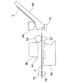
図17は、本発明に係る印刷動作状態判定システム及び印刷動作状態判定方法による印刷動作状態判定用印刷パターンの印刷並びに光学式センサによる走査及び検出を実行する際の条件を示すための印刷装置の側面図である。 FIG. 17 is a diagram showing a printing apparatus for showing conditions for executing printing operation state determination printing patterns by the printing operation state determination system and printing operation state determination method according to the present invention, and scanning and detection by an optical sensor. It is a side view.
印刷用紙Pにコックリングが発生している場合、前述のように、印刷用紙Pの先端部が未だ排紙ローラ76及びその従動ローラ75に挟持されていない状態では、印刷ヘッド36及び光学式センサ直下の領域に位置している印刷用紙Pの部分には、発生したコックリングがそのままの大きさで現れていることになり、印刷動作状態判定における誤判定を招く原因となる。
When cockling occurs in the printing paper P, as described above, the
そこで、本発明に係る印刷動作状態判定システム、印刷装置及び印刷動作状態判定方法においては、印刷用紙Pが紙送りローラ24及びその従動ローラ27により搬送されて印刷用紙Pの先端部が印刷ヘッド36直下の領域に到達しても直ちに印刷動作状態判定用印刷パターンの印刷を開始せず、印刷用紙Pの先端部が排紙ローラ76及びその従動ローラ75に挟持されるまで紙送りを行い、印刷用紙Pの先端部が排紙ローラ76及びその従動ローラ75に挟持されるのを待ってから、印刷用紙Pが紙送りローラ24及びその従動ローラ27並びに排紙ローラ76及びその従動ローラ75に挟持されている状態で、印刷動作状態判定用印刷パターンの印刷並びに光学式センサによる走査及び検出を実行する。
Therefore, in the printing operation state determination system, the printing apparatus, and the printing operation state determination method according to the present invention, the printing paper P is conveyed by the
このように、印刷用紙Pが紙送りローラ24及びその従動ローラ27並びに排紙ローラ76及びその従動ローラ75に挟持されている状態では、仮に印刷用紙Pにコックリングが発生していたとしても、紙送りローラ24及びその従動ローラ27と排紙ローラ76及びその従動ローラ75との間に位置する印刷用紙Pの部分、即ち、印刷ヘッド36及び光学式センサ直下の領域に位置している印刷用紙Pの部分においては、コックリングが非常に小さく抑制された状態となっている。
As described above, in the state where the printing paper P is sandwiched between the
従って、印刷用紙Pの先端部が排紙ローラ76及びその従動ローラ75に挟持されるのを待ってから、印刷用紙Pが紙送りローラ24及びその従動ローラ27並びに排紙ローラ76及びその従動ローラ75に挟持されている状態で印刷動作状態判定用印刷パターンの印刷を実行することにより、印刷媒体のコックリングの影響を非常に小さく抑制し又はほぼ完全に回避して、判定対象となる印刷動作状態を高精度に反映する判定用印刷パターンを得ることができる。
Accordingly, after waiting for the leading end of the printing paper P to be sandwiched between the
また、その高精度な判定用印刷パターンを使用して、同様に印刷用紙Pが紙送りローラ24及びその従動ローラ27並びに排紙ローラ76及びその従動ローラ75に挟持されている状態で光学式センサによる走査及び検出を実行することにより、印刷媒体のコックリングの影響を非常に小さく抑制し又はほぼ完全に回避して、正確な印刷動作状態判定を行うことができるので、その判定結果に基づいて印刷装置の設定を最適化し又はメンテナンスを行うことにより高画質印刷を実現することができる。
Similarly, the optical sensor is used in a state where the printing paper P is sandwiched between the
ところで、印刷動作状態判定用印刷パターンの印刷と、光学式センサによる走査及び検出とでは、光学式センサによる走査及び検出の方が印刷媒体のコックリングの影響をより大きく受けやすい。 By the way, in printing of a printing pattern for determining a printing operation state and scanning and detection by an optical sensor, scanning and detection by an optical sensor are more easily affected by cockling of the print medium.
そこで、印刷動作状態判定のスループットを向上させるために、印刷動作状態判定用印刷パターンの印刷は、印刷用紙Pの先端部が排紙ローラ76及びその従動ローラ75に挟持されるのを待たずに開始し、光学式センサによる走査及び検出は、印刷用紙Pの先端部が排紙ローラ76及びその従動ローラ75に挟持されるのを待ってから開始するようにしてもよい。
Therefore, in order to improve the throughput of the printing operation state determination, the printing of the printing operation state determination printing pattern is performed without waiting for the leading end portion of the printing paper P to be sandwiched between the
以上に説明した本発明に係る印刷動作状態判定システム、印刷装置及び印刷動作状態判定方法は、印刷装置の主走査方向における双方向(Bi−D)印刷を行う場合の往路インク滴下位置と復路インク滴下位置との相対位置を調整するBi−D調整のための印刷パターン検出、紙送り誤差を検出して紙送り量を調整するための印刷パターン検出の他、反射光の強度に反映される印刷媒体表面の印刷状態を印刷動作状態判定装置としての光学式センサによって検出することにより印刷装置の種々の動作状態を正確に判定するための印刷動作状態判定システム、印刷装置及び印刷動作状態判定方法として広く適用することが可能である。 The printing operation state determination system, the printing apparatus, and the printing operation state determination method according to the present invention described above include the forward ink drop position and the backward ink when performing bidirectional (Bi-D) printing in the main scanning direction of the printing apparatus. In addition to print pattern detection for Bi-D adjustment that adjusts the relative position to the dropping position, print pattern detection for adjusting paper feed amount by detecting paper feed error, printing reflected in reflected light intensity As a printing operation state determination system, a printing apparatus, and a printing operation state determination method for accurately determining various operation states of a printing apparatus by detecting a printing state of a medium surface by an optical sensor as a printing operation state determination apparatus It can be widely applied.
例えば、各インク吐出部からのインク吐出状態の判定にも適用することが可能であり、さらに、前述の双方向(Bi−D)印刷を行う場合のみならず、印刷装置の主走査方向における単方向(Uni−D)印刷を行う場合の各走査におけるインク滴下位置を調整するためのUni−D調整のための印刷パターン検出にも適用することが可能である。 For example, the present invention can also be applied to the determination of the ink discharge state from each ink discharge unit. Furthermore, not only when performing the above-described bidirectional (Bi-D) printing, but also in the main scanning direction of the printing apparatus. The present invention can also be applied to print pattern detection for Uni-D adjustment for adjusting the ink drop position in each scan when performing direction (Uni-D) printing.
また、本発明に係る印刷動作状態判定システム及び印刷動作状態判定方法の上記基本構成は、本発明に係る光学式センサ調整システム及び光学式センサ調整方法においても同様である。即ち、光学式センサ41の発光部41aの発光量及び受光部41bの検出感度の調整のための印刷パターン検出にも、上記基本構成は適用することができる。
The basic configuration of the printing operation state determination system and the printing operation state determination method according to the present invention is the same in the optical sensor adjustment system and the optical sensor adjustment method according to the present invention. That is, the above basic configuration can also be applied to print pattern detection for adjusting the light emission amount of the
本発明に係る光学式センサ調整システム及び光学式センサ調整方法により光学式センサ41の発光部41aの発光量及び受光部41bの検出感度の調整を行う場合、印刷媒体に印刷されるのは、正確には、印刷装置の動作状態を反映する印刷動作状態判定用印刷パターンではなく、光学式センサ41の調整用サンプルとしての調整用印刷パターンである。また、その調整用印刷パターンは、光学式センサによる走査及び検出の直前に又は並行して印刷してもよいし、予め印刷媒体に印刷されているものとしてもよい。
When adjusting the light emission amount of the
さらに、本発明に係る光学式センサ調整システム及び光学式センサ調整方法において使用する印刷媒体は、光学式センサ調整用印刷パターンが印刷されているものの他、未印刷状態のものを使用してもよい。 Furthermore, the print medium used in the optical sensor adjustment system and the optical sensor adjustment method according to the present invention may be one in which an optical sensor adjustment print pattern is printed or an unprinted one. .
本発明に係る印刷動作状態判定システム及び印刷動作状態判定方法並びに光学式センサ調整システム及び光学式センサ調整方法は、インクジェットプリンタに限らず、反射光の強度に反映される印刷媒体表面の印刷状態を検出することにより印刷装置の種々の動作状態を判定するための印刷動作状態判定装置として光学式センサを搭載している印刷装置全般の印刷動作状態判定システム及び印刷動作状態判定方法並びに光学式センサ調整システム及び光学式センサ調整方法に適用することが可能である。 The printing operation state determination system, the printing operation state determination method, the optical sensor adjustment system, and the optical sensor adjustment method according to the present invention are not limited to the ink jet printer, and the printing state of the print medium surface reflected in the intensity of reflected light is not limited. A printing operation state determination system, a printing operation state determination method, and an optical sensor adjustment of an entire printing apparatus equipped with an optical sensor as a printing operation state determination device for determining various operation states of the printing apparatus by detecting It can be applied to a system and an optical sensor adjustment method.
10 照射領域(スポット)
20 プリンタ
22 用紙スタッカ
25 ロータリーエンコーダ
26 プラテン板
28 キャリッジ
29 リニアエンコーダ
30 キャリッジモータ
31 搬送モータ
32 牽引ベルト
33 符号板
34 ガイドレール
36 印刷ヘッド
41 光センサ
41a 発光部
41b 受光部
50 受信バッファメモリ
52 イメージバッファ
54 システムコントローラ
54a 判定部
61 主走査ドライバ
62 副走査ドライバ
63 光センサドライバ
66 ヘッドドライバ
71 印刷パターン
15 紙検出センサ
64 給紙ローラ
24 紙送りローラ(搬送ローラ)
27 紙送りローラの従動ローラ
75 排紙ローラの従動ローラ
76 排紙ローラ
90 給紙トレイ
100 ホストコンピュータ
200 クリーニング機構
210 ヘッドキャップ
BL 印刷ブロック
BLa 空白印刷ブロック
BLb 正常印刷ブロック
CD 濃シアンインクノズル列
CL 淡シアンインクノズル列
KD ブラックインクノズル列
KL 淡ブラックインクノズル列
KP フォトブラックインクノズル列
MD 濃マゼンタインクノズル列
ML 淡マゼンタインクノズル列
YD イエローインクノズル列
La 投射光
Lb 反射光
MS 主走査方向
P 印刷用紙
SS 副走査方向
Vth 判定閾値
V0 空白印刷ブロックの出力信号レベル
VL 正常印刷ブロックの出力信号レベル(受光出力信号のピーク)
VL’検出距離変動や低周波ノイズにより下降した受光出力信号のピーク
Vx 検出距離変動や低周波ノイズにより上昇した受光出力信号のピーク
BLPn Bi−D調整用印刷ブロックパターン
FWP 往路印刷パターン
BWP 復路印刷パターン
BLPn−A Bi−D調整誤差最小(最低印刷濃度)印刷ブロックパターン
BLPn−D Bi−D調整誤差最大(最高印刷濃度)印刷ブロックパターン
R(N) 紙送り誤差検出用印刷パターンの基準パターン
A(N) 紙送り誤差検出用印刷パターンの調整用パターン
10 Irradiation area (spot)
20
27 Driven
Light receiving output signal peak Vx that has fallen due to VL 'detection distance fluctuation or low frequency noise Peak light receiving output signal that has risen due to detection distance fluctuation or low frequency noise BLPn Bi-D adjustment printing block pattern FWP Outgoing printing pattern BWP Incoming printing pattern BLPn-A Bi-D adjustment error minimum (minimum printing density) printing block pattern BLPn-D Bi-D adjustment error maximum (maximum printing density) printing block pattern R (N) Reference pattern A of paper feed error detection printing pattern ( N) Pattern for adjusting the print pattern for paper feed error detection
Claims (6)
印刷媒体を搬送方向下流側へ搬送するための紙送りローラ及びその第1従動ローラと、
前記紙送りローラ及び前記第1従動ローラよりも前記搬送方向下流側に設けられて、前記印刷媒体に、前記印刷装置の動作状態を反映する印刷動作状態判定用印刷パターンを印刷する印刷手段と、
前記印刷手段よりも前記搬送方向下流側に設けられた光学式センサであって、前記印刷媒体に対し照射光を出射する発光部、及び、前記印刷媒体表面において反射された反射光を受光して検出し、前記反射光の強度に応じた値の受光出力信号を変換生成する受光部を有する光学式センサと、
前記受光出力信号の値に基づいて印刷装置の動作状態を判定する判定部と、
前記印刷手段よりも前記搬送方向下流側に設けられて、前記印刷媒体を前記搬送方向下流側へ搬送するための排紙ローラ及びその第2従動ローラと、
を備えるとともに、
前記印刷手段は、前記印刷媒体が前記搬送方向下流側に搬送されて、前記印刷媒体の先端部が前記排紙ローラ及び前記第2従動ローラに挟持されるのを待たずして、前記印刷媒体に前記印刷動作状態判定用印刷パターンの印刷を開始し、
前記光学式センサは、前記紙送りローラ及び前記第1従動ローラ、並びに、前記排紙ローラ及び前記第2従動ローラに、前記印刷媒体が挟持されている状態の下で、前記発光部による前記印刷動作状態判定用印刷パターンへの照射光の出射と、前記受光部による反射光の検出を行う、
ことを特徴とする印刷動作状態判定システム。 A printing operation state determination system for determining an operation state of a printing apparatus,
A paper feed roller and a first driven roller for conveying the print medium to the downstream side in the conveying direction,
Printing means provided on the downstream side in the transport direction with respect to the paper feed roller and the first driven roller, and printing a printing pattern for determining a printing operation state that reflects an operation state of the printing apparatus on the printing medium ;
An optical sensor provided downstream of the printing unit in the transport direction , and a light emitting unit for emitting irradiation light to the print medium, and reflected light reflected on the surface of the print medium An optical sensor having a light receiving portion for detecting and converting and generating a light receiving output signal having a value corresponding to the intensity of the reflected light;
A determination unit that determines an operation state of the printing apparatus based on a value of the light reception output signal;
A discharge roller and a second driven roller thereof, which are provided downstream of the printing unit in the transport direction, and transport the print medium downstream in the transport direction;
The equipped Rutotomoni,
The printing means does not wait for the print medium to be conveyed downstream in the conveyance direction and the leading end of the print medium is sandwiched between the discharge roller and the second driven roller, and the print medium. To start printing the printing operation state determination print pattern,
The optical sensor is configured to perform the printing by the light emitting unit in a state where the print medium is sandwiched between the paper feed roller and the first driven roller, and the paper discharge roller and the second driven roller. Emitting the irradiation light to the operation state determination print pattern and detecting the reflected light by the light receiving unit;
A printing operation state determination system.
印刷媒体を搬送方向下流側へ搬送するための紙送りローラ及びその第1従動ローラと、
前記紙送りローラ及び前記第1従動ローラよりも前記搬送方向下流側に設けられて、前記印刷媒体に、検出感度調整用印刷パターンを印刷する印刷手段と、
前記印刷手段よりも前記搬送方向下流側に設けられた光学式センサであって、前記印刷媒体に対し照射光を出射する発光部、及び、前記印刷媒体表面において反射された反射光を受光して検出し、前記反射光の強度に応じた値の受光出力信号を変換生成する受光部を有する光学式センサと、
前記受光出力信号の値に基づいて前記光学式センサの前記発光部の発光量及び前記受光部の検出感度の調整状態を判定する判定部と、
前記印刷手段よりも前記搬送方向下流側に設けられて、前記印刷媒体を前記搬送方向下流側へ搬送するための排紙ローラ及びその第2従動ローラと、
を備えるとともに、
前記印刷手段は、前記印刷媒体が前記搬送方向下流側に搬送されて、前記印刷媒体の先端部が前記排紙ローラ及び前記第2従動ローラに挟持されるのを待たずして、前記印刷媒体に前記検出感度調整用印刷パターンの印刷を開始し、
前記光学式センサは、前記紙送りローラ及び前記第1従動ローラ、並びに、前記排紙ローラ及び前記第2従動ローラに、前記印刷媒体が挟持されている状態の下で、前記発光部による前記検出感度調整用印刷パターンへの照射光の出射と、前記受光部による反射光の検出を行う、
ことを特徴とする光学式センサ調整システム。 An optical sensor adjustment system in a printing apparatus,
A paper feed roller and a first driven roller for conveying the print medium to the downstream side in the conveying direction,
Printing means provided on the downstream side in the transport direction with respect to the paper feed roller and the first driven roller, and printing a print pattern for detecting sensitivity adjustment on the print medium ;
An optical sensor provided downstream of the printing unit in the transport direction , receiving a light emitting unit that emits irradiation light to the print medium, and reflected light reflected on the surface of the print medium An optical sensor having a light receiving portion for detecting and converting and generating a light receiving output signal having a value corresponding to the intensity of the reflected light;
A determination unit that determines an adjustment state of a light emission amount of the light emitting unit of the optical sensor and a detection sensitivity of the light receiving unit based on a value of the light reception output signal;
A discharge roller provided on the downstream side in the transport direction from the printing unit, and a second driven roller thereof for transporting the print medium downstream in the transport direction;
The equipped Rutotomoni,
The printing means waits for the printing medium to be conveyed downstream in the conveying direction and the leading end of the printing medium to be sandwiched between the paper discharge roller and the second driven roller, and the printing medium. To start printing the detection sensitivity adjustment print pattern,
The optical sensor detects the detection by the light emitting unit in a state where the print medium is sandwiched between the paper feed roller, the first driven roller, and the paper discharge roller and the second driven roller. Emitting the irradiation light to the sensitivity adjustment print pattern and detecting the reflected light by the light receiving unit,
An optical sensor adjustment system.
前記紙送りローラ及び前記第1従動ローラよりも前記搬送方向下流側に設けられて、前記印刷媒体に、印刷装置の動作状態を反映する印刷動作状態判定用印刷パターンを印刷する印刷手段と、
前記印刷手段よりも前記搬送方向下流側に設けられた光学式センサであって、前記印刷媒体に対し照射光を出射する発光部、及び、前記印刷媒体表面において反射された反射光を受光して検出し、前記反射光の強度に応じた値の受光出力信号を変換生成する受光部を有する光学式センサと、
前記受光出力信号の値に基づいて印刷装置の動作状態を判定する判定部と、
前記印刷手段よりも前記搬送方向下流側に設けられて、前記印刷媒体を前記搬送方向下流側へ搬送するための排紙ローラ及びその第2従動ローラと、
を備える印刷装置の印刷動作状態判定方法であって、
前記印刷媒体が前記搬送方向下流側に搬送されて、前記印刷媒体の先端部が前記排紙ローラ及び前記第2従動ローラに挟持されるのを待たずして、前記印刷手段が、前記印刷媒体に前記印刷動作状態判定用印刷パターンの印刷を開始する工程と、
前記紙送りローラ及び前記第1従動ローラ、並びに、前記排紙ローラ及び前記第2従動ローラに、前記印刷媒体が挟持されている状態の下で、前記光学式センサが、前記発光部による前記印刷動作状態判定用印刷パターンへの照射光の出射と、前記受光部による反射光の検出を行う工程と、
を備えることを特徴とする印刷動作状態判定方法。 A paper feed roller for transporting the print medium downstream in the transport direction and its first driven roller ;
Printing means provided on the downstream side in the transport direction with respect to the paper feed roller and the first driven roller, and printing a printing pattern for determining a printing operation state that reflects an operation state of a printing apparatus on the printing medium;
An optical sensor provided downstream of the printing unit in the transport direction, receiving a light emitting unit that emits irradiation light to the print medium, and reflected light reflected on the surface of the print medium An optical sensor having a light receiving portion for detecting and converting and generating a light receiving output signal having a value corresponding to the intensity of the reflected light;
A determination unit that determines an operation state of the printing apparatus based on a value of the light reception output signal;
A discharge roller provided on the downstream side in the transport direction from the printing unit, and a second driven roller thereof for transporting the print medium downstream in the transport direction;
A printing operation state determination method of the Ru printing apparatus comprising a,
Without waiting for the print medium to be transported downstream in the transport direction and the leading end of the print medium to be sandwiched between the paper discharge roller and the second driven roller, the printing means may include the print medium. Starting the printing of the printing pattern for determining the printing operation state,
In a state where the print medium is sandwiched between the paper feed roller and the first driven roller, and the paper discharge roller and the second driven roller, the optical sensor performs the printing by the light emitting unit. Emitting the irradiation light to the operation state determination print pattern, and detecting the reflected light by the light receiving unit;
Printing operation state determination method characterized by comprising a.
前記紙送りローラ及び前記第1従動ローラよりも前記搬送方向下流側に設けられて、前記印刷媒体に、検出感度調整用印刷パターンを印刷する印刷手段と、Printing means provided on the downstream side in the transport direction with respect to the paper feed roller and the first driven roller, and printing a print pattern for detecting sensitivity adjustment on the print medium;
前記印刷手段よりも前記搬送方向下流側に設けられた光学式センサであって、前記印刷媒体に対し照射光を出射する発光部、及び、前記印刷媒体表面において反射された反射光を受光して検出し、前記反射光の強度に応じた値の受光出力信号を変換生成する受光部を有する光学式センサと、An optical sensor provided downstream of the printing unit in the transport direction, receiving a light emitting unit that emits irradiation light to the print medium, and reflected light reflected on the surface of the print medium An optical sensor having a light receiving portion for detecting and converting and generating a light receiving output signal having a value corresponding to the intensity of the reflected light;
前記受光出力信号の値に基づいて前記光学式センサの前記発光部の発光量及び前記受光部の検出感度の調整状態を判定する判定部と、A determination unit that determines an adjustment state of a light emission amount of the light emitting unit of the optical sensor and a detection sensitivity of the light receiving unit based on a value of the light reception output signal;
前記印刷手段よりも前記搬送方向下流側に設けられて、前記印刷媒体を前記搬送方向下流側へ搬送するための排紙ローラ及びその第2従動ローラと、A discharge roller provided on the downstream side in the transport direction from the printing unit, and a second driven roller thereof for transporting the print medium downstream in the transport direction;
を備える印刷装置における光学式センサ調整方法であって、An optical sensor adjustment method in a printing apparatus comprising:
前記印刷媒体が前記搬送方向下流側に搬送されて、前記印刷媒体の先端部が前記排紙ローラ及び前記第2従動ローラに挟持されるのを待たずして、前記印刷手段が、前記印刷媒体に前記検出感度調整用印刷パターンの印刷を開始する工程と、Without waiting for the print medium to be transported downstream in the transport direction and the leading end of the print medium to be sandwiched between the paper discharge roller and the second driven roller, the printing means may include the print medium. Starting the printing of the detection sensitivity adjustment print pattern,
前記紙送りローラ及び前記第1従動ローラ、並びに、前記排紙ローラ及び前記第2従動ローラに、前記印刷媒体が挟持されている状態の下で、前記光学式センサが、前記発光部による前記検出感度調整用印刷パターンへの照射光の出射と、前記受光部による反射光の検出を行う工程と、The optical sensor detects the detection by the light emitting unit in a state where the print medium is sandwiched between the paper feed roller and the first driven roller, and the paper discharge roller and the second driven roller. Emitting the irradiation light to the sensitivity adjustment print pattern, and detecting the reflected light by the light receiving unit;
を備えることを特徴とする光学式センサ調整方法。An optical sensor adjustment method comprising:
Priority Applications (1)
| Application Number | Priority Date | Filing Date | Title |
|---|---|---|---|
| JP2003341406A JP4507544B2 (en) | 2003-09-30 | 2003-09-30 | Printing operation state determination system, printing operation state determination method, optical sensor adjustment system, and optical sensor adjustment method |
Applications Claiming Priority (1)
| Application Number | Priority Date | Filing Date | Title |
|---|---|---|---|
| JP2003341406A JP4507544B2 (en) | 2003-09-30 | 2003-09-30 | Printing operation state determination system, printing operation state determination method, optical sensor adjustment system, and optical sensor adjustment method |
Publications (3)
| Publication Number | Publication Date |
|---|---|
| JP2005103983A JP2005103983A (en) | 2005-04-21 |
| JP2005103983A5 JP2005103983A5 (en) | 2006-11-09 |
| JP4507544B2 true JP4507544B2 (en) | 2010-07-21 |
Family
ID=34536021
Family Applications (1)
| Application Number | Title | Priority Date | Filing Date |
|---|---|---|---|
| JP2003341406A Expired - Fee Related JP4507544B2 (en) | 2003-09-30 | 2003-09-30 | Printing operation state determination system, printing operation state determination method, optical sensor adjustment system, and optical sensor adjustment method |
Country Status (1)
| Country | Link |
|---|---|
| JP (1) | JP4507544B2 (en) |
Citations (3)
| Publication number | Priority date | Publication date | Assignee | Title |
|---|---|---|---|---|
| JPH1148464A (en) * | 1997-08-01 | 1999-02-23 | Canon Inc | Test printing method and ink jet recording apparatus |
| JP2000127370A (en) * | 1998-10-27 | 2000-05-09 | Canon Inc | Arranging method of optical sensor, print alignment method and printer employing it |
| JP2001277673A (en) * | 2000-03-31 | 2001-10-09 | Olympus Optical Co Ltd | Ink jet recorder |
-
2003
- 2003-09-30 JP JP2003341406A patent/JP4507544B2/en not_active Expired - Fee Related
Patent Citations (3)
| Publication number | Priority date | Publication date | Assignee | Title |
|---|---|---|---|---|
| JPH1148464A (en) * | 1997-08-01 | 1999-02-23 | Canon Inc | Test printing method and ink jet recording apparatus |
| JP2000127370A (en) * | 1998-10-27 | 2000-05-09 | Canon Inc | Arranging method of optical sensor, print alignment method and printer employing it |
| JP2001277673A (en) * | 2000-03-31 | 2001-10-09 | Olympus Optical Co Ltd | Ink jet recorder |
Also Published As
| Publication number | Publication date |
|---|---|
| JP2005103983A (en) | 2005-04-21 |
Similar Documents
| Publication | Publication Date | Title |
|---|---|---|
| CN101905576B (en) | Recording apparatus and recording position adjustment method | |
| KR100788665B1 (en) | Method for detecting missing nozzles in a inkjet printer | |
| US20100165015A1 (en) | System and Method for Selecting and Applying Appropriate Print Quality Defect Correction Technique to Compensate for Specified Print Quality Defect | |
| US20060203028A1 (en) | Apparatus and method for print quality control | |
| US8136903B2 (en) | Ink jet printing apparatus and ink jet printing method | |
| JP2005014617A (en) | Method for detecting missing nozzle of inkjet printer | |
| JP2010064266A (en) | Image forming apparatus | |
| US7066568B2 (en) | Determining method for determining whether ink was ejected or not, computer-readable medium, and printing apparatus | |
| US7036904B2 (en) | Printhead swath height measurement and compensation for ink jet printing | |
| JP2012011664A (en) | Recording apparatus and recording position adjusting method thereof | |
| JP2010162909A (en) | Optical sensor for determining print operation state, printer, and method for determining print operation state | |
| JP2007030254A (en) | Density detecting device for image forming apparatus | |
| JP4595298B2 (en) | Optical sensor for printing operation state determination, printing apparatus, and printing operation state determination method | |
| US9259917B2 (en) | Inkjet recording apparatus and recording position adjustment method | |
| JP2005059552A (en) | Photosensor for judging print operation state, printer, and method for judging print operation state | |
| JP2006334915A (en) | Method for inspecting ink discharge for printing device and printing device | |
| JP4507544B2 (en) | Printing operation state determination system, printing operation state determination method, optical sensor adjustment system, and optical sensor adjustment method | |
| JP4534190B2 (en) | Printing operation state determination apparatus, printing apparatus, and printing operation state determination method | |
| JP2005103995A (en) | System and method for determining printing operation state, and system and method for adjusting optical sensor | |
| JP2005103934A (en) | System for determining printing operation state, printer, and method for determining printing operation state | |
| JP2005067093A (en) | Device and system for judging print operation state, printer, and method for judging print operation state | |
| JP4174764B2 (en) | Paper feed error detecting device, printing apparatus, and paper feed error detecting method | |
| JP2005262813A (en) | Printing-operation state judging system, printing device, and printing-operation state decision method | |
| JP2005280038A (en) | Printer controller, printer, and printer controlling method | |
| JP2005280037A (en) | Printing medium inspecting device, printer and printing medium inspection method |
Legal Events
| Date | Code | Title | Description |
|---|---|---|---|
| A521 | Written amendment |
Free format text: JAPANESE INTERMEDIATE CODE: A523 Effective date: 20060921 |
|
| A621 | Written request for application examination |
Free format text: JAPANESE INTERMEDIATE CODE: A621 Effective date: 20060921 |
|
| A977 | Report on retrieval |
Free format text: JAPANESE INTERMEDIATE CODE: A971007 Effective date: 20090930 |
|
| A131 | Notification of reasons for refusal |
Free format text: JAPANESE INTERMEDIATE CODE: A131 Effective date: 20091002 |
|
| A521 | Written amendment |
Free format text: JAPANESE INTERMEDIATE CODE: A523 Effective date: 20091130 |
|
| TRDD | Decision of grant or rejection written | ||
| A01 | Written decision to grant a patent or to grant a registration (utility model) |
Free format text: JAPANESE INTERMEDIATE CODE: A01 Effective date: 20100413 |
|
| A01 | Written decision to grant a patent or to grant a registration (utility model) |
Free format text: JAPANESE INTERMEDIATE CODE: A01 |
|
| A61 | First payment of annual fees (during grant procedure) |
Free format text: JAPANESE INTERMEDIATE CODE: A61 Effective date: 20100426 |
|
| FPAY | Renewal fee payment (event date is renewal date of database) |
Free format text: PAYMENT UNTIL: 20130514 Year of fee payment: 3 |
|
| R150 | Certificate of patent or registration of utility model |
Ref document number: 4507544 Country of ref document: JP Free format text: JAPANESE INTERMEDIATE CODE: R150 Free format text: JAPANESE INTERMEDIATE CODE: R150 |
|
| FPAY | Renewal fee payment (event date is renewal date of database) |
Free format text: PAYMENT UNTIL: 20140514 Year of fee payment: 4 |
|
| S531 | Written request for registration of change of domicile |
Free format text: JAPANESE INTERMEDIATE CODE: R313531 |
|
| R350 | Written notification of registration of transfer |
Free format text: JAPANESE INTERMEDIATE CODE: R350 |
|
| LAPS | Cancellation because of no payment of annual fees |