JP2012503737A - Steam power generation facility for generating electrical energy - Google Patents
Steam power generation facility for generating electrical energy Download PDFInfo
- Publication number
- JP2012503737A JP2012503737A JP2011528292A JP2011528292A JP2012503737A JP 2012503737 A JP2012503737 A JP 2012503737A JP 2011528292 A JP2011528292 A JP 2011528292A JP 2011528292 A JP2011528292 A JP 2011528292A JP 2012503737 A JP2012503737 A JP 2012503737A
- Authority
- JP
- Japan
- Prior art keywords
- steam
- conduit
- bypass
- intermediate pressure
- cooler
- Prior art date
- Legal status (The legal status is an assumption and is not a legal conclusion. Google has not performed a legal analysis and makes no representation as to the accuracy of the status listed.)
- Pending
Links
Images

Classifications
-
- F—MECHANICAL ENGINEERING; LIGHTING; HEATING; WEAPONS; BLASTING
- F01—MACHINES OR ENGINES IN GENERAL; ENGINE PLANTS IN GENERAL; STEAM ENGINES
- F01K—STEAM ENGINE PLANTS; STEAM ACCUMULATORS; ENGINE PLANTS NOT OTHERWISE PROVIDED FOR; ENGINES USING SPECIAL WORKING FLUIDS OR CYCLES
- F01K7/00—Steam engine plants characterised by the use of specific types of engine; Plants or engines characterised by their use of special steam systems, cycles or processes; Control means specially adapted for such systems, cycles or processes; Use of withdrawn or exhaust steam for feed-water heating
- F01K7/16—Steam engine plants characterised by the use of specific types of engine; Plants or engines characterised by their use of special steam systems, cycles or processes; Control means specially adapted for such systems, cycles or processes; Use of withdrawn or exhaust steam for feed-water heating the engines being only of turbine type
- F01K7/165—Controlling means specially adapted therefor
-
- F—MECHANICAL ENGINEERING; LIGHTING; HEATING; WEAPONS; BLASTING
- F01—MACHINES OR ENGINES IN GENERAL; ENGINE PLANTS IN GENERAL; STEAM ENGINES
- F01K—STEAM ENGINE PLANTS; STEAM ACCUMULATORS; ENGINE PLANTS NOT OTHERWISE PROVIDED FOR; ENGINES USING SPECIAL WORKING FLUIDS OR CYCLES
- F01K13/00—General layout or general methods of operation of complete plants
- F01K13/02—Controlling, e.g. stopping or starting
- F01K13/025—Cooling the interior by injection during idling or stand-by
Abstract
本発明は、バイパス導管(12)を有する蒸気発電設備(1)に関する。前記バイパス導管は、生蒸気導管(5)を排気導管(6)と流体的に連結し、前記バイパス導管(12)内には、バイパス蒸気冷却器(20)が配置されており、前記バイパス蒸気冷却器は、緊急停止、運転開始、または運転終了に際して、前記バイパス導管(12)内を流れる蒸気を冷却し、それによって、前記バイパス導管(12)のために、より安価な材料を用いることができる。 The present invention relates to a steam power plant (1) having a bypass conduit (12). The bypass conduit fluidly connects the live steam conduit (5) to the exhaust conduit (6), and a bypass steam cooler (20) is disposed in the bypass conduit (12). The cooler cools the steam flowing through the bypass conduit (12) during an emergency stop, start-up, or end-of-operation, thereby using a less expensive material for the bypass conduit (12). it can.
Description
本発明は、電気的エネルギーを生成するための蒸気発電設備に関する。当該蒸気発電設備は、蒸気タービン、蒸気発生器、復水器、蒸気タービンと蒸気発生器とを流体的に連結する生蒸気導管、蒸気タービンと復水器とを流体的に連結する排気導管、および生蒸気導管と排気導管とを流体的に連結するバイパス導管を有する。 The present invention relates to a steam power generation facility for generating electrical energy. The steam power generation facility includes a steam turbine, a steam generator, a condenser, a live steam conduit that fluidly connects the steam turbine and the steam generator, an exhaust conduit that fluidly connects the steam turbine and the condenser, And a bypass conduit fluidly connecting the live steam conduit and the exhaust conduit.
蒸気発電設備においては、熱エネルギーが力学的エネルギーに変換され、最終的に電気的エネルギーに変換される。水蒸気は蒸気発生器から蒸気タービンなどの膨張機に流入し、蒸気は蒸気タービンにおいて運動出力下で膨張する。蒸気タービンから流出する蒸気は、下流の復水器において、熱吸収を通じて再び液化される。復水器内で生じた水は、給水ポンプによって再び蒸気発生器に搬送され、それによって密閉サイクルが成立する。 In a steam power generation facility, thermal energy is converted into mechanical energy and finally converted into electrical energy. The steam flows from the steam generator into an expander such as a steam turbine, and the steam expands under a motion output in the steam turbine. The steam flowing out of the steam turbine is liquefied again through heat absorption in the downstream condenser. The water generated in the condenser is transferred again to the steam generator by the feed pump, thereby establishing a closed cycle.
稼動状態において、蒸気発生器から流出した蒸気は蒸気タービンに流入する。このとき、当該蒸気は冷却される。蒸気圧は減少する。蒸気タービンから流出した蒸気は、復水器に供給される。運転開始、運転終了、または蒸気タービンの緊急停止に際して、蒸気タービンの上流に配置された生蒸気弁は閉止し、当該生蒸気はバイパス導管を通過する。当該バイパス導管は、蒸気タービンの排気導管に合流する。一般的に、排気導管は、再熱器に合流している場合には、低温再熱器導管と称される。当該再熱器内では、蒸気がより高い温度に加熱される。蒸気の温度が高くなればなるほど、導管、バイパス装置、および復水器へのバイパス蒸気注入に関する費用は高くなる。蒸気温度が約720℃に達するように試みられる。このような高い温度を得るためには、ニッケルベースの材料など、特別な材料を用いる必要がある。ニッケルベースの材料とは、ニッケル含有量が約40重量%〜50重量%の材料である。しかしながら、このようなニッケルベースの材料は、比較的高価である。他方で、ニッケルベースの材料には、特に高い熱的負荷を与えることができる。 In operation, the steam flowing out of the steam generator flows into the steam turbine. At this time, the steam is cooled. The vapor pressure decreases. The steam flowing out from the steam turbine is supplied to the condenser. At the start of operation, the end of operation, or the emergency stop of the steam turbine, the live steam valve disposed upstream of the steam turbine is closed, and the live steam passes through the bypass conduit. The bypass conduit joins the exhaust conduit of the steam turbine. Generally, the exhaust conduit is referred to as a low temperature reheater conduit when it joins the reheater. Within the reheater, the steam is heated to a higher temperature. The higher the temperature of the steam, the higher the costs associated with injecting bypass steam into the conduit, bypass device, and condenser. An attempt is made to reach a steam temperature of about 720 ° C. In order to obtain such a high temperature, it is necessary to use a special material such as a nickel-based material. A nickel-based material is a material having a nickel content of about 40% to 50% by weight. However, such nickel-based materials are relatively expensive. On the other hand, nickel-based materials can be subjected to particularly high thermal loads.
ニッケルベースの材料よりも有利な材料を用いることが望ましい。この点から出発して、本発明は、高温に適しており、かつ、比較的有利に建設することができる蒸気発電設備を開示することを課題として設定している。 It is desirable to use materials that are advantageous over nickel-based materials. Starting from this point, the present invention is set to disclose a steam power generation facility that is suitable for high temperatures and that can be constructed relatively advantageously.
本課題は、電気的エネルギーを生成するための蒸気発電設備によって解決される。当該蒸気発電設備は、蒸気タービン、蒸気発生器、復水器、蒸気タービンと蒸気発生器とを流体的に連結する生蒸気導管、蒸気タービンと復水器とを流体的に連結する排気導管、および生蒸気導管と排気導管とを流体的に連結するバイパス導管を有する。バイパス導管には、バイパス蒸気冷却器が設けられており、当該バイパス蒸気冷却器は、バイパス導管内を流れる蒸気またはバイパス導管内に停滞する蒸気を冷却するために形成されている。 This problem is solved by a steam power generation facility for generating electrical energy. The steam power generation facility includes a steam turbine, a steam generator, a condenser, a live steam conduit that fluidly connects the steam turbine and the steam generator, an exhaust conduit that fluidly connects the steam turbine and the condenser, And a bypass conduit fluidly connecting the live steam conduit and the exhaust conduit. The bypass conduit is provided with a bypass steam cooler, which is configured to cool steam flowing in the bypass conduit or steam stagnating in the bypass conduit.
バイパス蒸気冷却器で蒸気を冷却することによって、冷却器の下流の部材を、ニッケルベースの材料を用いずに形成することができる。バイパス蒸気冷却器の下流に配置された導管は冷却されるので、バイパス導管にかかる熱的負荷はより小さくなる。熱的負荷がより小さくなることによって、高価なニッケルベースの材料を用いる必要はなくなる。 By cooling the steam with a bypass steam cooler, the downstream component of the cooler can be formed without using a nickel-based material. Since the conduit located downstream of the bypass steam cooler is cooled, the thermal load on the bypass conduit is smaller. The smaller thermal load eliminates the need to use expensive nickel-based materials.
排気導管は、再熱器に合流している限りにおいて、低温再熱器導管とも称される。当該再熱器内では、蒸気がより高い温度に加熱される。 The exhaust conduit is also referred to as a low temperature reheater conduit as long as it joins the reheater. Within the reheater, the steam is heated to a higher temperature.
有利なさらなる構成は、従属請求項に記載されている。 Advantageous further configurations are described in the dependent claims.
バイパス蒸気冷却器内の蒸気を、凝縮液、蒸気、または水と蒸気との混合物などの冷却媒体を吹き付けることによって冷却すると有利である。蒸気発電設備において、凝縮液、または水と蒸気との混合物を用いることは比較的容易である。これらの冷却媒体は、蒸気発電設備内において利用可能だからである。それによって、追加的に用いる導管は最小限に抑えられる。 It is advantageous to cool the steam in the bypass steam cooler by blowing a cooling medium such as condensate, steam or a mixture of water and steam. It is relatively easy to use condensate or a mixture of water and steam in a steam power plant. This is because these cooling media can be used in the steam power generation facility. Thereby, additional conduits are minimized.
バイパス蒸気冷却器は、生蒸気導管からバイパス導管への第1の分岐点のすぐ下流に配置されていると有利である。バイパス蒸気冷却器は、第1の分岐点の下流で、可能な限り当該分岐点の近くに配置されると理想的である。それによって、蒸気発電設備の建設費用がさらに削減されるという利点がある。高価なニッケルベースの材料を用いることが回避されるからである。バイパス蒸気冷却器が、生蒸気導管からバイパス導管への第1の分岐点の近くに配置されていればいるほど、当該第1の分岐点とバイパス蒸気冷却器との間で必要とされるニッケルベースの材料は少なくなる。 The bypass steam cooler is advantageously arranged just downstream of the first branch point from the live steam conduit to the bypass conduit. Ideally, the bypass steam cooler is positioned as close as possible to the branch point downstream of the first branch point. Thereby, there is an advantage that the construction cost of the steam power generation facility is further reduced. This is because the use of expensive nickel-based materials is avoided. The more the bypass steam cooler is located near the first branch point from the live steam conduit to the bypass conduit, the more nickel required between the first branch point and the bypass steam cooler. Less base material.
さらなる有利な構成において、バイパス蒸気冷却器と高圧バイパス弁との間の距離は、冷却媒体が蒸気と完全に混合されるように選択される。 In a further advantageous configuration, the distance between the bypass steam cooler and the high pressure bypass valve is selected so that the cooling medium is thoroughly mixed with the steam.
冷却媒体を蒸気と完全に混合することによって、バイパス導管が効果的に冷却され、したがって、蒸気発電設備建設時の費用をさらに削減できる。バイパス導管に用いるニッケルベースの材料がより少なくてすむからである。以下に、本発明を図を基に詳細に説明する。図は一部概略的であり、縮尺に従ってはいない。 By thoroughly mixing the cooling medium with the steam, the bypass conduit is effectively cooled, thus further reducing the cost of constructing the steam power plant. This is because less nickel-based material is used for the bypass conduit. Hereinafter, the present invention will be described in detail with reference to the drawings. The figure is partially schematic and not to scale.
異なる図中の同一の参照符号は、同一の意味を有している。 The same reference numerals in different figures have the same meaning.
図1には、従来技術に係る蒸気発電設備1が示されている。蒸気発電設備1は、蒸気発生器2と蒸気タービン3とを有している。蒸気タービン3は、高圧部分タービン3a、中圧部分タービン3b、および低圧部分タービン3cと、復水器4とを有する。さらに、生蒸気導管5が設けられている。生蒸気導管5は、蒸気タービン3を蒸気発生器2と流体的に連結する。蒸気タービン3の下流には、排気導管6が配置されている。排気導管6は、蒸気タービン3を復水器4と流体的に連結する。高圧部分タービン3aと復水器4との間には、再熱器7が設けられている。再熱器7に流入する蒸気は、より高い温度に加熱され、高温再熱器導管8を通じて、中圧部分タービン3bに搬送される。排気導管6は、低温再熱器導管9とも称される。蒸気タービン3の上流には、急速閉止および制御弁10が配置されている。中圧部分タービン3bの上流にも、急速閉止および制御弁11が配置されている。生蒸気導管5は、バイパス導管12を介して、排気導管6もしくは低温再熱器導管9と流体的に連結されている。バイパス導管12には、高圧バイパス弁13が配置されている。
FIG. 1 shows a steam power generation facility 1 according to the prior art. The steam power generation facility 1 includes a steam generator 2 and a
高温再熱器導管8は、中圧バイパス導管14を介して、復水器4と流体的に連結されている。中圧バイパス導管14には、中圧バイパス弁17が配置されている。運転開始、運転終了、または蒸気タービン3の緊急停止に際して、蒸気は、生蒸気導管5からバイパス導管12を経由して、低温再熱器導管9に搬送される。そのために、急速閉止および制御弁10が閉止され、高圧バイパス弁13が開放される。バイパス導管12に流入する生蒸気の温度は比較的高いので、当該蒸気には、低温再熱器導管9に流入する前に、冷却ユニット16において冷却媒体15が吹き付けられる。続いて、当該蒸気は、再熱器7、高温再熱器導管8を経由して中圧バイパス導管14の方へ案内され、復水器4内に搬送される。そのために、急速閉止および制御弁11が閉止され、中圧バイパス弁17が開放される。中圧バイパス弁17の下流で、蒸気には再び冷却ユニット19において冷却媒体18が吹き付けられ、それによって、復水器はエネルギー量を受容することができる。蒸気の温度と圧力とは比較的高いので、生蒸気導管5、バイパス導管12、高温再熱器導管9、および中圧バイパス導管14は、再熱器7の圧力および温度に耐え得るように設計されなければならない。蒸気の温度が高くなればなるほど、導管5、12、9、8、1、弁17、13、および冷却ユニット16、19にかかる費用は高くなる。
The
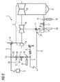
図2には、本発明に係る蒸気発電設備1が示されている。図1に示された蒸気発電設備1との違いは、バイパス導管12および中圧バイパス導管14に、バイパス蒸気冷却器20もしくは中圧バイパス蒸気冷却器21が配置されているという点にある。バイパス蒸気冷却器20および中圧バイパス蒸気冷却器21は、バイパス導管12および中圧バイパス導管14内を流れる蒸気または停滞する蒸気を冷却するために形成されている。バイパス蒸気冷却器20および中圧バイパス蒸気冷却器21を用いて、凝縮液、蒸気、または水と蒸気との混合物が、流れる蒸気または停滞する蒸気の中に吹き込まれる。したがって、流れる蒸気または停滞する蒸気の温度は低下する。蒸気内に供給された冷却媒体22は、当該蒸気を冷却する。バイパス導管12および中圧バイパス導管14への冷却媒体22の吹き付け装置は、可能な限り第1の分岐点23の近く、もしくは第2の分岐点24の下流に配置した方が良い。バイパス蒸気冷却器20と高圧バイパス弁13との間の距離は、蒸気が冷却媒体22と完全に混合されるように選択される。また、中圧バイパス蒸気冷却器21と中圧バイパス弁17との間の距離は、蒸気が冷却媒体22と完全に混合されるように選択される。
FIG. 2 shows a steam power generation facility 1 according to the present invention. A difference from the steam power generation facility 1 shown in FIG. 1 is that a bypass steam cooler 20 or an intermediate pressure bypass steam cooler 21 is arranged in the
生蒸気のパラメータが適切な値を有している場合、冷却ユニット16もしくは19を省略しても良い。そのためには、生蒸気の質量流量、圧力、および温度と、水の注入量と、温度とが許容値でなければならない。バイパス蒸気冷却器20および中圧バイパス蒸気冷却器21は、バイパス弁13および中圧バイパス弁17が開放されるとすぐに、オンにされる。それによって、冷却されたバイパス導管25もしくは26における、許容できない温度超過が効果的に回避される。
If the live steam parameter has an appropriate value, the cooling
バイパス弁13が閉止するとすぐに、バイパス蒸気冷却器20の上流の温度が、導管25における許容温度を下回るまで、バイパス蒸気冷却器20が稼動する。排水溝または予熱導管が、冷却されたバイパス導管25および26に配置される限りにおいて、当該バイパス導管は、バイパス蒸気冷却器20および中圧バイパス蒸気冷却器21の上流の温度が、冷却された導管25もしくは26における許容温度を下回るまで、閉止されたままでいなければならない。
As soon as the
1 蒸気発電設備
2 蒸気発生器
3 蒸気タービン
3a 高圧部分タービン
3b 中圧部分タービン
3c 低圧部分タービン
4 復水器
5 生蒸気導管
6 排気導管
7 再熱器
8 高温再熱器導管
9 低温再熱器導管
10 急速閉止および制御弁
11 急速閉止および制御弁
12 バイパス導管
13 高圧バイパス弁
14 中圧バイパス導管
15 冷却媒体
16 冷却ユニット
17 中圧バイパス弁
18 冷却媒体
19 冷却ユニット
20 バイパス蒸気冷却器
21 中圧バイパス蒸気冷却器
22 冷却媒体
23 第1の分岐点
24 第2の分岐点
25 バイパス導管
26 バイパス導管
DESCRIPTION OF SYMBOLS 1 Steam power generation equipment 2
Claims (12)
蒸気タービン(3)、蒸気発生器(2)、復水器(4)、前記蒸気タービン(3)と前記蒸気発生器(2)とを流体的に連結する生蒸気導管(5)、前記蒸気タービン(3)と前記復水器(4)とを流体的に連結する排気導管(6)、および前記生蒸気導管(5)と前記排気導管(6)とを流体的に連結するバイパス導管(12)を有する蒸気発電設備(1)において、
バイパス蒸気冷却器(20)が前記バイパス導管(12)内に設けられており、前記バイパス蒸気冷却器は、前記バイパス導管(12)内を流れる蒸気を冷却するために形成されていることを特徴とする蒸気発電設備(1)。 A steam power generation facility (1) for generating electrical energy,
A steam turbine (3), a steam generator (2), a condenser (4), a live steam conduit (5) fluidly connecting the steam turbine (3) and the steam generator (2), the steam An exhaust conduit (6) fluidly connecting the turbine (3) and the condenser (4), and a bypass conduit (fluidly connecting the live steam conduit (5) and the exhaust conduit (6)) 12) in a steam power plant (1) having
A bypass steam cooler (20) is provided in the bypass conduit (12), the bypass steam cooler being formed to cool steam flowing in the bypass conduit (12). Steam power generation equipment (1).
低温再熱器導管(9)が設けられており、前記低温再熱器導管は、前記高圧部分タービン(3a)の蒸気排出口を前記再熱器(7)と流体的に連結しており、
前記バイパス導管(12)は、前記生蒸気導管(5)を前記低温再熱器導管(9)と流体的に連結していることを特徴とする請求項2に記載の蒸気発電設備(1)。 Having a reheater (7),
A low temperature reheater conduit (9) is provided, the low temperature reheater conduit fluidly connecting the steam outlet of the high pressure partial turbine (3a) with the reheater (7);
The steam power plant (1) according to claim 2, wherein the bypass conduit (12) fluidly connects the live steam conduit (5) with the cold reheater conduit (9). .
前記高温再熱器導管は、前記再熱器(7)を前記中圧部分タービン(3b)と流体的に連結しており、
中圧バイパス導管(14)が設けられており、前記中圧バイパス導管は、前記高温再熱器導管(8)を前記復水器(4)と流体的に連結しており、
中圧バイパス蒸気冷却器(21)が前記中圧バイパス導管(14)に設けられており、前記中圧バイパス蒸気冷却器は、前記中圧バイパス導管(14)を流れる蒸気を冷却するために形成されていることを特徴とする請求項2または3に記載の蒸気発電設備(1)。 A high temperature reheater conduit (8),
The hot reheater conduit fluidly connects the reheater (7) with the intermediate pressure partial turbine (3b);
An intermediate pressure bypass conduit (14) is provided, the intermediate pressure bypass conduit fluidly connecting the hot reheater conduit (8) with the condenser (4);
An intermediate pressure bypass steam cooler (21) is provided in the intermediate pressure bypass conduit (14), the intermediate pressure bypass steam cooler formed to cool the steam flowing through the intermediate pressure bypass conduit (14). The steam power generation facility (1) according to claim 2 or 3, wherein the steam power generation facility (1) is provided.
Applications Claiming Priority (3)
| Application Number | Priority Date | Filing Date | Title |
|---|---|---|---|
| EP08016801.6 | 2008-09-24 | ||
| EP08016801A EP2213847A1 (en) | 2008-09-24 | 2008-09-24 | Steam power assembly for creating electrical energy |
| PCT/EP2009/061993 WO2010034659A2 (en) | 2008-09-24 | 2009-09-16 | Steam power plant for generating electrical energy |
Related Child Applications (1)
| Application Number | Title | Priority Date | Filing Date |
|---|---|---|---|
| JP2012173690A Division JP5314178B2 (en) | 2008-09-24 | 2012-08-06 | Steam power generation facility for generating electrical energy |
Publications (1)
| Publication Number | Publication Date |
|---|---|
| JP2012503737A true JP2012503737A (en) | 2012-02-09 |
Family
ID=42060159
Family Applications (2)
| Application Number | Title | Priority Date | Filing Date |
|---|---|---|---|
| JP2011528292A Pending JP2012503737A (en) | 2008-09-24 | 2009-09-16 | Steam power generation facility for generating electrical energy |
| JP2012173690A Active JP5314178B2 (en) | 2008-09-24 | 2012-08-06 | Steam power generation facility for generating electrical energy |
Family Applications After (1)
| Application Number | Title | Priority Date | Filing Date |
|---|---|---|---|
| JP2012173690A Active JP5314178B2 (en) | 2008-09-24 | 2012-08-06 | Steam power generation facility for generating electrical energy |
Country Status (8)
| Country | Link |
|---|---|
| US (1) | US8925321B2 (en) |
| EP (2) | EP2213847A1 (en) |
| JP (2) | JP2012503737A (en) |
| KR (1) | KR101322148B1 (en) |
| CN (1) | CN102165145B (en) |
| PL (1) | PL2326800T3 (en) |
| RU (1) | RU2481477C2 (en) |
| WO (1) | WO2010034659A2 (en) |
Families Citing this family (8)
| Publication number | Priority date | Publication date | Assignee | Title |
|---|---|---|---|---|
| EP2428653A1 (en) * | 2010-09-10 | 2012-03-14 | Siemens Aktiengesellschaft | Single intermediate pressure operation mode for solar driven steam turbine plants |
| GB2485836A (en) | 2010-11-27 | 2012-05-30 | Alstom Technology Ltd | Turbine bypass system |
| EP2500549A1 (en) * | 2011-03-14 | 2012-09-19 | Siemens Aktiengesellschaft | Injection aperture for a steam power plant |
| EP3262284B1 (en) | 2015-02-24 | 2019-01-02 | Siemens Aktiengesellschaft | Combined cycle power plant having supercritical steam turbine |
| JP2015187448A (en) * | 2015-07-27 | 2015-10-29 | 三菱重工業株式会社 | Ship main engine steam turbine installation and ship equipped with the same |
| DE102016104538B3 (en) * | 2016-03-11 | 2017-01-19 | Mitsubishi Hitachi Power Systems Europe Gmbh | Thermal steam power plant with improved waste heat recovery and method of operation thereof |
| JP6654497B2 (en) * | 2016-04-05 | 2020-02-26 | 三菱日立パワーシステムズ株式会社 | Steam turbine plant |
| EP3258074A1 (en) | 2016-06-14 | 2017-12-20 | Siemens Aktiengesellschaft | Steam power plant for generating electrical energy |
Citations (8)
| Publication number | Priority date | Publication date | Assignee | Title |
|---|---|---|---|---|
| JPS5812604U (en) * | 1981-07-16 | 1983-01-26 | 株式会社東芝 | Two-stage reheat turbine bypass device |
| JPS5891309A (en) * | 1981-11-13 | 1983-05-31 | ウエスチングハウス エレクトリック コ−ポレ−ション | Bypassing device for steam turbine |
| JPS60228710A (en) * | 1984-04-27 | 1985-11-14 | Toshiba Corp | Control device for steam turbine |
| JPS6193208A (en) * | 1984-10-15 | 1986-05-12 | Hitachi Ltd | Turbine bypass system |
| JPH0577501U (en) * | 1992-03-24 | 1993-10-22 | 株式会社東芝 | Steam turbine plant |
| JPH0814009A (en) * | 1994-06-30 | 1996-01-16 | Toshiba Corp | Operation control method for pressurized fluidized bed boiler type composite cycle power plant |
| JP2002341947A (en) * | 2001-05-21 | 2002-11-29 | Mitsubishi Heavy Ind Ltd | Pressure flow rate controller |
| DE10227709A1 (en) * | 2001-06-25 | 2003-02-27 | Alstom Switzerland Ltd | Steam turbine power plant has overflow line bypassing intermediate overheater between high pressure steam turbine and medium or low pressure turbine |
Family Cites Families (16)
| Publication number | Priority date | Publication date | Assignee | Title |
|---|---|---|---|---|
| CH406247A (en) * | 1963-07-23 | 1966-01-31 | Sulzer Ag | Steam power plant with forced steam generator and reheater |
| SU642493A1 (en) * | 1977-01-19 | 1979-01-15 | Предприятие П/Я А-3513 | Power plant |
| US4435963A (en) | 1980-05-05 | 1984-03-13 | Tempo G | Means for retaining jewelery for interlocking with precise preforms |
| US4352270A (en) * | 1980-06-26 | 1982-10-05 | Westinghouse Electric Corp. | Method and apparatus for providing process steam of desired temperature and pressure |
| US4357803A (en) * | 1980-09-05 | 1982-11-09 | General Electric Company | Control system for bypass steam turbines |
| US4576008A (en) * | 1984-01-11 | 1986-03-18 | Westinghouse Electric Corp. | Turbine protection system for bypass operation |
| US4598551A (en) * | 1985-10-25 | 1986-07-08 | General Electric Company | Apparatus and method for controlling steam turbine operating conditions during starting and loading |
| US4873827A (en) * | 1987-09-30 | 1989-10-17 | Electric Power Research Institute | Steam turbine plant |
| RU2099542C1 (en) * | 1990-01-23 | 1997-12-20 | Фостер Вилер Энержи Ой | Steam power plant and method of control of same |
| SE469606B (en) * | 1991-12-20 | 1993-08-02 | Abb Carbon Ab | PROCEDURE AT STARTING AND LOW-LOAD OPERATION OF THE FLOWING PAN AND DEVICE FOR IMPLEMENTATION OF THE PROCEDURE |
| JPH06228710A (en) | 1993-01-29 | 1994-08-16 | Nippon Steel Corp | Stainless steel for diesel exhaust system excellent in corrosion resistance |
| RU2090542C1 (en) | 1994-04-12 | 1997-09-20 | Красноярская государственная техническая академия | Method of destruction of solid rocket fuel and method of preparation of nitrosobenzene solution for destruction of solid rocket fuel |
| EP1288761B1 (en) * | 2001-07-31 | 2017-05-17 | General Electric Technology GmbH | Method for controlling a low pressure bypass system |
| ITTO20050873A1 (en) * | 2005-12-15 | 2007-06-16 | Ansaldo Energia Spa | DEVICE FOR THE OPENING COMMAND OF AN INTERCEPTION VALVE IN A STEAM TURBINE SYSTEM PROVIDED WITH A BY-PASS LINE |
| JP4619958B2 (en) * | 2006-01-20 | 2011-01-26 | 株式会社東芝 | Steam turbine control valve and steam turbine power plant |
| EP1881164B1 (en) * | 2006-07-21 | 2016-09-14 | Ansaldo Energia S.P.A. | Device for regulating the intercept valves of a steam-turbine plant |
-
2008
- 2008-09-24 EP EP08016801A patent/EP2213847A1/en not_active Withdrawn
-
2009
- 2009-09-16 WO PCT/EP2009/061993 patent/WO2010034659A2/en active Application Filing
- 2009-09-16 JP JP2011528292A patent/JP2012503737A/en active Pending
- 2009-09-16 CN CN200980137447.0A patent/CN102165145B/en active Active
- 2009-09-16 KR KR1020117006679A patent/KR101322148B1/en active IP Right Grant
- 2009-09-16 EP EP09783070.7A patent/EP2326800B1/en not_active Not-in-force
- 2009-09-16 PL PL09783070T patent/PL2326800T3/en unknown
- 2009-09-16 US US13/119,438 patent/US8925321B2/en not_active Expired - Fee Related
- 2009-09-16 RU RU2011116163/06A patent/RU2481477C2/en not_active IP Right Cessation
-
2012
- 2012-08-06 JP JP2012173690A patent/JP5314178B2/en active Active
Patent Citations (8)
| Publication number | Priority date | Publication date | Assignee | Title |
|---|---|---|---|---|
| JPS5812604U (en) * | 1981-07-16 | 1983-01-26 | 株式会社東芝 | Two-stage reheat turbine bypass device |
| JPS5891309A (en) * | 1981-11-13 | 1983-05-31 | ウエスチングハウス エレクトリック コ−ポレ−ション | Bypassing device for steam turbine |
| JPS60228710A (en) * | 1984-04-27 | 1985-11-14 | Toshiba Corp | Control device for steam turbine |
| JPS6193208A (en) * | 1984-10-15 | 1986-05-12 | Hitachi Ltd | Turbine bypass system |
| JPH0577501U (en) * | 1992-03-24 | 1993-10-22 | 株式会社東芝 | Steam turbine plant |
| JPH0814009A (en) * | 1994-06-30 | 1996-01-16 | Toshiba Corp | Operation control method for pressurized fluidized bed boiler type composite cycle power plant |
| JP2002341947A (en) * | 2001-05-21 | 2002-11-29 | Mitsubishi Heavy Ind Ltd | Pressure flow rate controller |
| DE10227709A1 (en) * | 2001-06-25 | 2003-02-27 | Alstom Switzerland Ltd | Steam turbine power plant has overflow line bypassing intermediate overheater between high pressure steam turbine and medium or low pressure turbine |
Also Published As
| Publication number | Publication date |
|---|---|
| EP2326800B1 (en) | 2016-11-16 |
| CN102165145A (en) | 2011-08-24 |
| WO2010034659A3 (en) | 2010-08-26 |
| EP2213847A1 (en) | 2010-08-04 |
| RU2481477C2 (en) | 2013-05-10 |
| PL2326800T3 (en) | 2017-05-31 |
| JP5314178B2 (en) | 2013-10-16 |
| US8925321B2 (en) | 2015-01-06 |
| WO2010034659A2 (en) | 2010-04-01 |
| EP2326800A2 (en) | 2011-06-01 |
| CN102165145B (en) | 2014-05-14 |
| KR101322148B1 (en) | 2013-10-28 |
| JP2012211595A (en) | 2012-11-01 |
| KR20110047245A (en) | 2011-05-06 |
| US20110167827A1 (en) | 2011-07-14 |
| RU2011116163A (en) | 2012-10-27 |
Similar Documents
| Publication | Publication Date | Title |
|---|---|---|
| JP5314178B2 (en) | Steam power generation facility for generating electrical energy | |
| US7765807B2 (en) | Method for warming-up a steam turbine | |
| JP6245404B1 (en) | Combustion equipment and power generation equipment | |
| JP5027887B2 (en) | Steam turbine power plant and method for increasing steam mass flow of a high pressure turbine in a steam turbine power plant | |
| JP5558686B2 (en) | Method for operating a combined cycle power plant and a combined cycle power plant implementing the method | |
| JP2005527808A (en) | Method and apparatus for generating electricity from heat generated in at least one high temperature reactor core | |
| JP5860597B2 (en) | System and method for preheating exhaust heat recovery boiler piping | |
| JP2010014114A (en) | Steam turbine overload valve and method associated with the same | |
| WO2011082949A2 (en) | Combined cycle power plant and method of operating such power plant | |
| KR101628611B1 (en) | Supercritical CO2 generation system using multistage compressing and expanding of working fluid | |
| KR20160120471A (en) | Supercritical CO2 generation system | |
| CN110199100A (en) | Gas theory electricity generation system and gas theory electricity-generating method | |
| BR112020010611A2 (en) | lng gas regasification | |
| US9404395B2 (en) | Selective pressure kettle boiler for rotor air cooling applications | |
| US20230349322A1 (en) | Gas turbine comprising thermal energy store, method for operating same, and method for modifying same | |
| KR101936327B1 (en) | Combined Heat and power system using supercritical carbon dioxide power cycle | |
| CA2461086C (en) | Method of power generation from pressure control stations of a natural gas distribution system | |
| US20150121871A1 (en) | Forced cooling in steam turbine plants | |
| JP3964709B2 (en) | Gas turbine fuel gas supply system and operation method thereof | |
| KR101628619B1 (en) | generation system having temperature control device for heat exchanger | |
| KR101559728B1 (en) | Cogeneration Plant Cooling System | |
| RU2310765C1 (en) | Power generation method | |
| EP3258074A1 (en) | Steam power plant for generating electrical energy | |
| CN114483307B (en) | Efficiency improving system and control method of hydrogen fuel gas turbine | |
| KR101487287B1 (en) | Power Plant |
Legal Events
| Date | Code | Title | Description |
|---|---|---|---|
| A131 | Notification of reasons for refusal |
Free format text: JAPANESE INTERMEDIATE CODE: A131 Effective date: 20120508 |
|
| A02 | Decision of refusal |
Free format text: JAPANESE INTERMEDIATE CODE: A02 Effective date: 20121030 |