JP2012500406A - Positioning system - Google Patents
Positioning system Download PDFInfo
- Publication number
- JP2012500406A JP2012500406A JP2011522514A JP2011522514A JP2012500406A JP 2012500406 A JP2012500406 A JP 2012500406A JP 2011522514 A JP2011522514 A JP 2011522514A JP 2011522514 A JP2011522514 A JP 2011522514A JP 2012500406 A JP2012500406 A JP 2012500406A
- Authority
- JP
- Japan
- Prior art keywords
- positioning system
- positioning
- object carrier
- carrier device
- drive mechanism
- Prior art date
- Legal status (The legal status is an assumption and is not a legal conclusion. Google has not performed a legal analysis and makes no representation as to the accuracy of the status listed.)
- Pending
Links
- 238000005259 measurement Methods 0.000 claims abstract description 32
- 239000002131 composite material Substances 0.000 description 14
- 230000033001 locomotion Effects 0.000 description 11
- 230000003287 optical effect Effects 0.000 description 5
- 230000005484 gravity Effects 0.000 description 3
- 230000002411 adverse Effects 0.000 description 2
- 238000006243 chemical reaction Methods 0.000 description 2
- 230000008878 coupling Effects 0.000 description 2
- 238000010168 coupling process Methods 0.000 description 2
- 238000005859 coupling reaction Methods 0.000 description 2
- 238000005286 illumination Methods 0.000 description 2
- 238000000386 microscopy Methods 0.000 description 2
- 238000004873 anchoring Methods 0.000 description 1
- 230000005540 biological transmission Effects 0.000 description 1
- 238000000339 bright-field microscopy Methods 0.000 description 1
- 238000010276 construction Methods 0.000 description 1
- 239000006185 dispersion Substances 0.000 description 1
- 230000000694 effects Effects 0.000 description 1
- 239000011521 glass Substances 0.000 description 1
- 238000010348 incorporation Methods 0.000 description 1
- 238000000034 method Methods 0.000 description 1
- 238000004801 process automation Methods 0.000 description 1
- 210000002105 tongue Anatomy 0.000 description 1
Images
Classifications
-
- G—PHYSICS
- G02—OPTICS
- G02B—OPTICAL ELEMENTS, SYSTEMS OR APPARATUS
- G02B21/00—Microscopes
- G02B21/24—Base structure
- G02B21/26—Stages; Adjusting means therefor
Landscapes
- Physics & Mathematics (AREA)
- Chemical & Material Sciences (AREA)
- Analytical Chemistry (AREA)
- General Physics & Mathematics (AREA)
- Optics & Photonics (AREA)
- Microscoopes, Condenser (AREA)
- Control Of Position Or Direction (AREA)
- Instruments For Measurement Of Length By Optical Means (AREA)
Abstract
本発明は、対象物(11)を技術的機器、特に、観察、計測、または処理システム等に対して相対的に位置決めする位置決めシステム(10)に関し、位置決めされる対象物を受けるオブジェクトキャリア装置(13)、および上記オブジェクトキャリア装置を位置決めする位置決め装置(12)、を含み、上記位置決め装置は、オブジェクトキャリア装置を駆動する駆動機構を有し、上記駆動機構は、オブジェクトキャリア装置の2軸方向の位置決めが可能になるように配置された2つのリニアモータ(21,22)を有し、上記位置決め装置は、計測機構(23)を有し、上記駆動機構と計測機構とが、位置決め装置の参照基部(26)とオブジェクトキャリア装置との間に介在するように配置されている。 The present invention relates to a positioning system (10) for positioning an object (11) relative to technical equipment, in particular an observation, measurement or processing system, etc. 13), and a positioning device (12) for positioning the object carrier device, wherein the positioning device has a drive mechanism for driving the object carrier device, and the drive mechanism is arranged in a biaxial direction of the object carrier device. It has two linear motors (21, 22) arranged so that positioning is possible, the positioning device has a measuring mechanism (23), and the driving mechanism and measuring mechanism refer to the positioning device. It arrange | positions so that it may interpose between a base part (26) and an object carrier apparatus.
Description
本発明は、対象物を技術的機器(technical facility)、特に、観察、計測、または処理システム等に対して相対的に位置決めする位置決めシステムに関し、位置決めされる対象物を受けるオブジェクトキャリア装置、および上記オブジェクトキャリア装置を位置決めする位置決め装置を含み、上記位置決め装置は、オブジェクトキャリア装置を駆動する駆動機構(drive facility)を有し、上記駆動機構は、オブジェクトキャリア装置の2軸方向の位置決めが可能になるように配置された2つのリニアモータを有し、上記位置決め装置は、計測機構(measurement facility)を有する。 The present invention relates to a positioning system for positioning an object relative to a technical facility, in particular an observation, measurement or processing system, etc., an object carrier device for receiving the object to be positioned, and the above A positioning device for positioning the object carrier device, wherein the positioning device has a drive facility for driving the object carrier device, and the driving mechanism enables positioning of the object carrier device in two axial directions. And the positioning device has a measurement facility.
2軸方向に移動可能な位置決め対象物の位置決めシステムは長らく知られ、通例、複合テーブル、またはXYテーブルとも呼ばれている。複合テーブルは、位置決めされる対象物を受けるために設けられたオブジェクトキャリア装置を位置決め装置に結合する、互いに直交するように配置された2つのガイドを有する。このように、複合テーブルは、また、特に高い精度の要求が適用される他の応用分野の中で、顕微鏡検査、および計測システムにも用いられる。対象物またはサンプルを伴ったサンプルホルダは、観察または計測のために、複合テーブルを用いて、顕微鏡の対物レンズまたは計測センサに対して相対的に1つ以上の位置に移動される。高い精度の要求を満足するために、従来の公知の複合テーブルは、一般に、例えばスピンドルドライブ、ラックアンドピニオン、ボーデンケーブル(Bowden cable)、または歯付ベルトドライブなどの機械的アクチュエータを含む。自動化された位置決め動作を可能にするために、他の公知の技術は、これらのドライバに回転タイプの電動モータが設けられる。さらに、リニアモータの形式で構成された電動モータベースのドライバもまた知られ、モータの動作から移動動作への直接変換を可能にする。 Positioning systems for positioning objects that are movable in two axial directions have long been known and are commonly referred to as composite tables or XY tables. The composite table has two guides arranged orthogonal to each other, which couples an object carrier device provided for receiving the object to be positioned to the positioning device. Thus, composite tables are also used in microscopy and metrology systems, among other applications where particularly high accuracy requirements are applied. The sample holder with the object or sample is moved to one or more positions relative to the microscope objective or measurement sensor using a composite table for observation or measurement. In order to meet the requirements of high accuracy, conventional known composite tables typically include mechanical actuators, such as spindle drives, rack and pinions, Bowden cables, or toothed belt drives. In order to allow an automated positioning operation, other known techniques are provided in these drivers with rotary electric motors. In addition, electric motor-based drivers configured in the form of linear motors are also known, allowing direct conversion from motor operation to movement.
位置決めされる対象物の動きと同様に、特に計測が行われる場合や特定の位置に繰り返しセットされる必要がある場合には、実際の位置の決定がとりわけ重要である。そこで、通常、上記のような位置決めシステムには、比較的正確な位置の決定ができる補助的な計測装置が設けられる。しかし、計測装置は通常インクリメンタル計測装置の形式で構成され、つまり、通常、計測装置の電源が投入された後に、計測装置のレファレンスのために、計測システムのゼロポイントが訪れられ、または複合テーブルの座標系が定義されなければならない。そして、スケールユニットが目的の位置または長さを決定するために、ゼロポイントから開始されてカウントされる。 Similar to the movement of the object to be positioned, the determination of the actual position is particularly important, especially when measurements are to be taken or when it is necessary to repeatedly set a specific position. Therefore, the positioning system as described above is usually provided with an auxiliary measuring device that can determine a relatively accurate position. However, the measuring device is usually configured in the form of an incremental measuring device, that is, after the measuring device is turned on, the measuring system zero point is visited for the reference of the measuring device, or in the composite table. A coordinate system must be defined. The scale unit is then counted starting from the zero point to determine the target position or length.
従来から知られた位置決めシステムの欠点は、駆動装置が複合テーブルに付加的なコンポーネントとして配置されていることである。特に、複合テーブルの外縁の領域に配置された電動モータの重量は、荷重負荷のアンバランスを引き起こし、複合テーブルの重心の変移となる。したがって、位置決めシステムの支持は、好ましくないトルク負荷の影響を受け、位置決めシステムの計測精度に不利な影響を与える。これは、特に、回転モータが、複合テーブルの一側面に突出して用いられ、または複合テーブルの底面にフランジで取り付けられる場合の一例である。回転モータは、さらに、回転動作から移動動作への必要な変換のために、機械的コンポーネントが種々のノイズおよび振動を発生させ、計測結果に不都合な影響を与え得るという欠点を有している。 A disadvantage of the known positioning systems is that the drive is arranged as an additional component on the composite table. In particular, the weight of the electric motor arranged in the region of the outer edge of the composite table causes an imbalance in load and causes a change in the center of gravity of the composite table. Thus, the support of the positioning system is affected by an undesirable torque load, which adversely affects the measurement accuracy of the positioning system. This is an example in particular when the rotary motor is used to protrude from one side of the composite table or is attached to the bottom of the composite table with a flange. Rotational motors also have the disadvantage that mechanical components can generate various noises and vibrations, which can adversely affect the measurement results, due to the necessary conversion from rotational motion to moving motion.
特に、位置決めシステムが顕微鏡と伴に用いられる場合には、構造上の理由で位置決めシステムの配置のために小さなスペースしか許容されない標準的な市販の顕微鏡上で位置決めシステムが使用を意図されるので、位置決めシステムの組み付け高さは、できるだけ低いことが重要である。光が透過する顕微鏡検査では(In transmitted light microscopy)、顕微鏡の光学コンポーネントは、対象物に両側から非常に近づくように移動できなければならない。したがって、複合テーブルをできるだけ薄く構成することが望ましい。従来知られた複合テーブルは、駆動機構および/または計測装置が、平坦で比較的薄いオブジェクトキャリア装置の縁部に配置されることによって、これを達成している。しかし、この配置は、対応する計測結果へのネガティブな効果と伴に、前記のような重量分散の欠点をもたらす。 In particular, if the positioning system is used with a microscope, the positioning system is intended for use on standard commercial microscopes where only a small space is allowed for positioning system positioning for structural reasons, It is important that the assembly height of the positioning system is as low as possible. For light transmitted microscopy (In transmitted light microscopy), the optical components of the microscope must be able to move very close to the object from both sides. Therefore, it is desirable to make the composite table as thin as possible. Previously known composite tables achieve this by placing the drive mechanism and / or measuring device at the edge of a flat and relatively thin object carrier device. However, this arrangement has the disadvantages of weight dispersion as described above, with a negative effect on the corresponding measurement results.
したがって、本発明の目的は、簡潔な手段によって作製できる、精度の向上した位置決めシステムを提供することである。この問題は、位置決めシステムの請求項1の特徴によって解決される。 Accordingly, it is an object of the present invention to provide a positioning system with improved accuracy that can be made by simple means. This problem is solved by the features of claim 1 of the positioning system.
本発明の、対象物を技術的機器、特に、観察、計測、または処理システム等に対して相対的に位置決めする位置決めシステムは、位置決めされる対象物を受けるオブジェクトキャリア装置、および上記オブジェクトキャリア装置を位置決めする位置決め装置を含み、上記位置決め装置は、オブジェクトキャリア装置を駆動する駆動機構を有し、上記駆動機構は、オブジェクトキャリア装置の2軸方向の位置決めが可能になるように配置された2つのリニアモータを有し、上記位置決め装置は、計測機構を有し、上記駆動機構と計測機構とが、位置決め装置の参照基部とオブジェクトキャリア装置との間に横たわるように配置されている。 According to the present invention, a positioning system for positioning an object relative to a technical device, particularly an observation, measurement, or processing system, includes an object carrier device that receives the object to be positioned, and the object carrier device. A positioning device for positioning, the positioning device having a drive mechanism for driving the object carrier device, wherein the drive mechanism is arranged in two linear directions so as to enable positioning of the object carrier device in two axial directions. The positioning device includes a motor, and the measuring device includes a measuring mechanism, and the driving mechanism and the measuring mechanism are disposed so as to lie between the reference base of the positioning device and the object carrier device.
特に電動モータベースの駆動機構としてのリニアモータの使用は、特に平坦な位置決めシステムの構築を容易にする。位置決め装置の参照基部は、技術的機器に相対的に不動、または強固に固定され、対象物を伴うオブジェクトキャリア装置は、2つのリニアモータによって複合テーブルのように互いに相対的にX軸およびY軸方向に移動することができる。駆動機構、および計測装置が、位置決め装置の参照基部と、オブジェクトキャリア装置との間に配置されていることにより、位置決めシステムの荷重分布は、質量の中心が、オブジェクトキャリア装置の図心に相対的に比較的近く配置される結果となる。このことは、位置決め装置の参照基部上、または位置決め装置の参照基部とオブジェクトキャリア装置との間に配置された計測装置上で重力による不利なトルクが加わることがないので、向上した計測精度が達成されることを意味する。さらに、計測装置の重心に近い、またはオブジェクトキャリア装置と位置決め装置との接続に近い配置は、オブジェクトキャリア装置の縁部に配置された計測装置に比べて、トルクの揺れ動き(torque-induced tilting movements)が、計測装置からオブジェクトキャリア装置の回転中心への長い距離に亘って増幅されることがほとんどないので、特に正確な計測結果を支持する。 In particular, the use of a linear motor as a drive mechanism based on an electric motor facilitates the construction of a particularly flat positioning system. The reference base of the positioning device is relatively immovable or firmly fixed to the technical equipment, and the object carrier device with the object is relatively X-axis and Y-axis relative to each other like a composite table by two linear motors. Can move in the direction. Since the drive mechanism and the measuring device are arranged between the reference base of the positioning device and the object carrier device, the load distribution of the positioning system is such that the center of mass is relative to the centroid of the object carrier device. As a result. This means that there is no unfavorable torque due to gravity on the reference base of the positioning device or on the measuring device placed between the reference base of the positioning device and the object carrier device, so improved measurement accuracy is achieved. Means that Furthermore, the arrangement close to the center of gravity of the measuring device or close to the connection between the object carrier device and the positioning device is a torque-induced tilting movements compared to the measuring device arranged at the edge of the object carrier device. However, since it is hardly amplified over a long distance from the measuring device to the center of rotation of the object carrier device, a particularly accurate measurement result is supported.
位置決め装置の参照基部に対するオブジェクトキャリア装置の明示されていない(unspecified)位置の絶対値が計測装置によって直ちに決定できるならば、特に有利である。公知のインクリメンタル計測装置と比べて、スケールユニットのインクリメンタルカウンティングの絶対的な計測が算出されるのに先立ってオブジェクトキャリア装置により最初に移動されることが必要なゼロポイントも、定義される座標系のリファレンスポイントも存在しないことは有利である。このように、位置決めシステムは、スイッチオンされた直後に、対象物の位置の絶対的な計測値をもたらすことができる。特に、位置決めシステムが処理の自動化のために用いられる場合には、装置がスイッチオンされた後にレファレンスポイントに移動する必要性が排除されるので、時間の短縮が可能になる。 It is particularly advantageous if the absolute value of the unspecified position of the object carrier device relative to the reference base of the positioning device can be determined immediately by the measuring device. Compared to known incremental measuring devices, the zero point that must first be moved by the object carrier device before the absolute measurement of the incremental counting of the scale unit is calculated is also defined in the defined coordinate system. It is advantageous that there are no reference points. In this way, the positioning system can provide an absolute measurement of the position of the object immediately after being switched on. In particular, if the positioning system is used for process automation, the need to move to the reference point after the device is switched on is eliminated, thus reducing time.
一実施例では、計測装置は、磁気計測装置であってもよい。磁気計測装置は、匹敵する要求精度の光学計測装置に比べて安価に製造することができ、磁気計測装置の組み付けサイズは、光学計測装置に比べて小さい。特にガラススケールとレンズ、および必要な光路は、光学計測装置の小型化に対して不利である。 In one embodiment, the measurement device may be a magnetic measurement device. The magnetic measuring device can be manufactured at a lower cost than an optical measuring device with comparable required accuracy, and the assembly size of the magnetic measuring device is smaller than that of the optical measuring device. In particular, the glass scale, the lens, and the necessary optical path are disadvantageous for miniaturization of the optical measuring device.
他の実施例では、計測装置は、複数の計測ユニットを含んでもよい。第1の計測ユニットはX軸に割り当てられ、第2の計測ユニットはY軸に割り当てられ得る。それぞれの計測ユニットの位置の評価によって、対象物の位置が容易に決定できる。 In another embodiment, the measurement device may include a plurality of measurement units. The first measurement unit may be assigned to the X axis and the second measurement unit may be assigned to the Y axis. The position of the object can be easily determined by evaluating the position of each measurement unit.
また、計測ユニットは、互いに相対的に移動可能なセンサユニットとスケールとを備えてもよい。スケールまたはセンサユニットは、位置決め装置の参照基部に接続され得、センサユニットまたはスケールはオブジェクトキャリア装置に接続され、オブジェクトキャリア装置が移動する間、センサユニットとスケールとの間で相対的な動きが生じる。計測ユニットは、また、参照基部とオブジェクトキャリア装置との間に特に容易に配置することができる。 The measurement unit may include a sensor unit and a scale that can move relative to each other. The scale or sensor unit may be connected to the reference base of the positioning device, the sensor unit or scale being connected to the object carrier device, and relative movement between the sensor unit and the scale occurs while the object carrier device moves. . The measuring unit can also be arranged particularly easily between the reference base and the object carrier device.
もし、スケールが複数の磁気トラックを有する場合には、それぞれのトラックがセンサによってスキャンされ得る。それらのトラックのうちの1つは、磁極の正確な配置を有し得、インクリメンタルスケールの形式でスケールユニットを提供する。そして1つ以上の追加のトラックは、第1のトラックに対して位相がずれた磁極を有し得、絶対的な位置の決定が可能になる。したがって、以前のゼロポイントの定義なしに、絶対的な位置の即座の算出が行われ得る。例えば3つの磁気トラックが形成され得る。 If the scale has multiple magnetic tracks, each track can be scanned by a sensor. One of those tracks may have an exact placement of the magnetic poles, providing a scale unit in the form of an incremental scale. The one or more additional tracks can then have magnetic poles that are out of phase with respect to the first track, allowing absolute position determination. Thus, an immediate calculation of the absolute position can be performed without the previous zero point definition. For example, three magnetic tracks can be formed.
リニアガイドおよびリニアモータのために、位置決めシステムは、位置決めシステムへの軸方向の外力に大きな抵抗で抗することができないので、オブジェクトキャリア装置が位置決め装置の固定装置によって固定され得ることは特に有利である。固定装置は、搬送またはサービス中断の間、オブジェクトキャリア装置を位置決め装置の参照基部に相対的に固定でき、オブジェクトキャリア装置の好ましくない動き、および適当な場合には位置決めシステムの損傷を防止できる。このことは、動作が中断(break)した後に、対象物の観察または計測が、最後の位置から開始して、継続して(without interruption)続け得ることを意味する。 For linear guides and linear motors, it is particularly advantageous that the object carrier device can be fixed by the fixing device of the positioning device, since the positioning system cannot resist the axial external force on the positioning system with great resistance. is there. The anchoring device can fix the object carrier device relative to the reference base of the positioning device during transport or service interruption, preventing undesired movement of the object carrier device and, where appropriate, damage to the positioning system. This means that after the operation breaks, the observation or measurement of the object can continue without interruption starting from the last position.
さらに、固定装置は、2つの安定なエンド位置に移動し得る電磁石を含んでもよい。1つのエンド位置では、オブジェクトキャリア装置は、意図された範囲内で、参照基部に相対的に自由に動くことができる。他のエンド位置では、位置決め装置またはオブジェクトキャリア装置の可動コンポーネントは、圧力ばめまたは確実な嵌合(force fit or positive fit)で固定される。電磁石または固定装置は、単に、例えば、位置決めシステムのオフまたはオン時に、短い電圧パルスによって活性化され得る。 Further, the fixation device may include an electromagnet that can move to two stable end positions. In one end position, the object carrier device is free to move relative to the reference base within the intended range. In other end positions, the movable component of the positioning device or object carrier device is fixed with a pressure fit or a positive fit. The electromagnet or fixing device can simply be activated by a short voltage pulse, for example when the positioning system is turned off or on.
一実施例では、位置決め装置を制御する制御装置が、位置決め装置に組み込まれ得る。制御装置は、例えばリニアモータを駆動でき、計測装置を解析できる。制御装置は、リニアモータと計測装置との組み合わせにマッチすることが好ましい。制御装置が位置決め装置に直接組み込まれるのと同様に、位置決め装置の外への制御装置の配置も考えられ、制御装置は、位置決め装置にデータ交換手段を介して接続され得る。 In one embodiment, a controller that controls the positioning device may be incorporated into the positioning device. The control device can drive a linear motor, for example, and can analyze the measurement device. The control device preferably matches the combination of the linear motor and the measuring device. Just as the control device is incorporated directly into the positioning device, an arrangement of the control device outside the positioning device is also conceivable, and the control device can be connected to the positioning device via data exchange means.
対象物の破損を防止するために、対象物を技術的機器または位置決めシステムに、力が制限された形で位置させることも好ましい。それは、特に、駆動機構によって加えられる力が制御装置によって制限され得る場合に有利である。リニアモータの場合には、これは、制御装置を用いてモータ電流を制限することによって、特に簡単に達成できる。 In order to prevent damage to the object, it is also preferred to place the object on a technical device or positioning system in a force-limited manner. It is particularly advantageous when the force applied by the drive mechanism can be limited by the control device. In the case of a linear motor, this can be achieved particularly simply by limiting the motor current using a control device.
他の実施例では、駆動装置、計測装置、および制御装置の接続ケーブルが、固定的に配置されてもよい。この実施例は、特に、位置決め装置の参照基部とオブジェクトキャリア装置との間に設けられる駆動機構と計測装置の統合によって達成され得る。このようにして、駆動機構または計測装置にフレキシブルに供給され、またはオブジェクトキャリア装置に移動可能に接続されるケーブルは必要がない。よって、ケーブルが、繰り返される動きによってストレスを受けることもなく、ケーブルに作用する力による計測結果の破損も防止され得る。 In another embodiment, the connecting cables for the driving device, the measuring device, and the control device may be fixedly arranged. This embodiment can be achieved in particular by integrating a drive mechanism and a measuring device provided between the reference base of the positioning device and the object carrier device. In this way, there is no need for a cable that is flexibly supplied to the drive mechanism or measuring device or movably connected to the object carrier device. Therefore, the cable is not subjected to stress due to repeated movements, and damage to the measurement result due to the force acting on the cable can be prevented.
位置決め装置は、計測装置または制御装置による位置の解析が行われ得るように構成してもよい。これは、絶対的な位置の直接決定が、計測装置自体内または制御装置内で例えばソフトウェアを用いて容易に行われ得ることを意味する。 The positioning device may be configured such that the position can be analyzed by the measuring device or the control device. This means that the direct determination of the absolute position can easily be performed in the measuring device itself or in the control device, for example using software.
オブジェクトキャリア装置のエンド位置において、対象物が自動的に位置決めシステムによって掴まれる(handled)ようにしてもよい。エンド位置では、例えば、オブジェクトキャリア装置が自動的に対象物にフィットされ得る。関連するエンド位置においてインクリメンタルな計測値の決定のためにゼロポイントに移動する必要性が排除される場合に、特に簡単に実施され得る。 The object may be automatically handled by the positioning system at the end position of the object carrier device. In the end position, for example, the object carrier device can be automatically fitted to the object. This can be done particularly simply if the need to move to a zero point for the determination of an incremental measurement at the relevant end position is eliminated.
オブジェクトキャリア装置が顕微鏡テーブルを含む場合には、位置決めシステムは顕微鏡において有利に使用することができる。 If the object carrier device includes a microscope table, the positioning system can be advantageously used in a microscope.
オブジェクトキャリア装置がさらにサンプルホルダを含む場合には、観察または計測されるサンプルまたは対象物が、オブジェクトキャリア装置の顕微鏡テーブルに対して定義された位置に容易に位置決めされ得る。 If the object carrier device further includes a sample holder, the sample or object to be observed or measured can be easily positioned at a defined position relative to the microscope table of the object carrier device.
サンプルホルダが駆動装置のリニアモータに直接結合される場合、サンプルホルダまたは対象物は、顕微鏡テーブル上を軸に沿って移動し得る。これは、位置決め装置のためのガイドの構造を簡潔にする。 If the sample holder is directly coupled to the linear motor of the drive, the sample holder or object can move along the axis on the microscope table. This simplifies the structure of the guide for the positioning device.
以下、添付図を参照して、発明がより詳細に述べられる。 The invention will now be described in more detail with reference to the accompanying drawings.
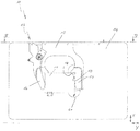
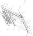
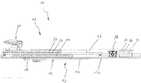
図1から図5の対比は、透過光顕微鏡による可能な観察または計測のために、図示しない対象物またはサンプルを受けるサンプルキャリア11を有する位置決めシステム10を示す。位置決めシステム10は、位置決め装置12とオブジェクトキャリア装置13とから形成されている。オブジェクトキャリア装置13は、顕微鏡テーブル14と、サンプルホルダ15とを含み、サンプルホルダ15は、移動アーム16と固定アーム17とを有する1対のトングの形で構成されている。アーム17の2つの接触表面18,19は、サンプルキャリア11のための定義されたホルダを形成している。顕微鏡テーブル14は、X軸に沿って移動可能であり、サンプルホルダ15は互いに相対的に90°の角度を成すY軸に沿って移動可能である。さらに、顕微鏡テーブル14には、サンプルの照明または観察を容易にするために開口20が設けられている。
1 to 5 show a
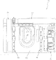
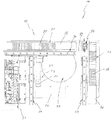
位置決め装置12は、共に駆動装置を形成する2つのリニアモータ21,22を含む。さらに、実質的に磁気ストリップ24とセンサヘッド25とから構成される計測装置23が設けられている。ベースプレート26は、位置決め装置12の参照基部を形成する。上記ベースプレート26は、顕微鏡上の、位置決めシステム10の固定されたアセンブリのための、より詳しくは示されない顕微鏡および固定装置の照明または観察装置のための開口27を含む。
The
さらに、位置決め装置12に、顕微鏡テーブル14の結合、および長手方向の移動のための2つのリニアガイド28,29、ならびにサンプルホルダ15の連結および長手方向の移動のためのリニアガイド30が設けられている。移動は、リニアモータ21,22によって行われ、それぞれのリニアモータ21,22は、中間コイル35,36、上磁気部31,32、および下磁気部33,34を備えている。計測装置23によって出力される計測信号は、位置決めシステム10に組み込まれた制御装置37に記録される。リニアモータ21,22、および双安定電磁石38の制御は、制御装置37によって達成され、それはブレーキロッド39と伴に固定装置を形成する。特に、計測装置23と伴に顕微鏡テーブル14とベースプレート26との間に設けられるリニアモータ21,22の組み込みによって、位置決めシステム10の特にコンパクトでフラットな実施例が可能になり、リニアモータ21,22だけの配置によって、オブジェクトキャリア装置13のエンド位置においてもバランスウェイトの分散が確保される。
Further, the
Claims (16)
位置決めされる対象物を受けるオブジェクトキャリア装置(13)、および
上記オブジェクトキャリア装置を位置決めする位置決め装置(12)、
を含み、
上記位置決め装置は、オブジェクトキャリア装置を駆動する駆動機構を有し、
上記駆動機構は、オブジェクトキャリア装置の2軸方向の位置決めが可能になるように配置された2つのリニアモータ(21,22)を有し、
上記位置決め装置は、計測機構(23)を有し、
上記駆動機構と計測機構とが、位置決め装置の参照基部(26)とオブジェクトキャリア装置との間に横たわるように配置されていることを特徴とする位置決めシステム。 A positioning system (10) for positioning an object (11) relative to a technical instrument, in particular an observation, measurement or processing system,
An object carrier device (13) for receiving an object to be positioned, and a positioning device (12) for positioning the object carrier device;
Including
The positioning device has a drive mechanism for driving the object carrier device,
The drive mechanism has two linear motors (21, 22) arranged so that the object carrier device can be positioned in two axes.
The positioning device has a measurement mechanism (23),
A positioning system, wherein the drive mechanism and the measurement mechanism are arranged so as to lie between a reference base (26) of the positioning device and the object carrier device.
位置決め装置(12)の参照基部(26)に対するオブジェクトキャリア装置(13)の明示されていない位置の絶対値が、計測装置(23)によって直接決定され得ることを特徴とする位置決めシステム。 The positioning system of claim 1, comprising:
Positioning system, characterized in that the absolute value of the unspecified position of the object carrier device (13) relative to the reference base (26) of the positioning device (12) can be determined directly by the measuring device (23).
計測装置(23)は、磁気計測装置であることを特徴とする位置決めシステム。 A positioning system according to any one of claims 1 and 2,
A positioning system, wherein the measuring device (23) is a magnetic measuring device.
計測装置は2つの計測ユニットを含むことを特徴とする位置決めシステム。 A positioning system according to any one of claims 1 to 3,
A positioning system, wherein the measuring device includes two measuring units.
計測ユニットは、互いに相対移動可能なセンサユニット(25)と、スケール(24)とを含むことを特徴とする位置決めシステム。 The positioning system of claim 4, comprising:
The positioning system includes a sensor unit (25) and a scale (24) that are movable relative to each other.
スケール(24)は、複数の磁気トラックを含むことを特徴とする位置決めシステム。 The positioning system of claim 5, comprising:
A positioning system, wherein the scale (24) includes a plurality of magnetic tracks.
オブジェクトキャリア装置(13)は、位置決め装置(12)の固定装置によって固定され得ることを特徴とする位置決めシステム。 A positioning system according to any one of claims 1 to 6,
Positioning system, characterized in that the object carrier device (13) can be fixed by a fixing device of the positioning device (12).
固定装置は、電磁石(38)を含むことを特徴とする位置決めシステム。 The positioning system of claim 7, comprising:
The positioning system, wherein the fixing device comprises an electromagnet (38).
位置決め装置を制御するための制御装置(37)が位置決め装置(12)に組み込まれていることを特徴とする位置決めシステム。 A positioning system according to any one of claims 1 to 8,
A positioning system characterized in that a control device (37) for controlling the positioning device is incorporated in the positioning device (12).
駆動機構によって加えられる力が制御装置(37)によって制限され得ることを特徴とする位置決めシステム。 The positioning system of claim 9, comprising:
Positioning system, characterized in that the force applied by the drive mechanism can be limited by the control device (37).
駆動機構、計測装置(23)、および制御装置(37)の接続ケーブルが固定的に配置されていることを特徴とする位置決めシステム。 A positioning system according to any one of claims 9 and 10, comprising:
A positioning system, wherein connection cables for a drive mechanism, a measuring device (23), and a control device (37) are fixedly arranged.
位置決め装置(12)は、計測装置(23)または制御装置(37)によって位置の解析が行われ得るように構成されていることを特徴とする位置決めシステム。 A positioning system according to any one of claims 9 and 11, comprising:
The positioning system is characterized in that the positioning device (12) can be analyzed by a measuring device (23) or a control device (37).
オブジェクトキャリア装置(13)のエンド位置において、対象物(11)が自動的に位置決めシステム(10)によって掴まれ得る事を特徴とする位置決めシステム。 A positioning system according to any one of claims 1 to 12,
Positioning system characterized in that the object (11) can be automatically gripped by the positioning system (10) at the end position of the object carrier device (13).
オブジェクトキャリア装置(13)は、顕微鏡テーブル(14)を含むことを特徴とする位置決めシステム。 A positioning system according to any one of claims 1 to 13,
Positioning system, characterized in that the object carrier device (13) comprises a microscope table (14).
オブジェクトキャリア装置(13)がサンプルホルダ(15)を含むことを特徴とする位置決めシステム。 15. The positioning system of claim 14, comprising
Positioning system, characterized in that the object carrier device (13) comprises a sample holder (15).
サンプルホルダ(15)が駆動機構のリニアモータ(21)に直接結合されていることを特徴とする位置決めシステム。 The positioning system of claim 15, comprising:
Positioning system, characterized in that the sample holder (15) is directly coupled to the linear motor (21) of the drive mechanism.
Applications Claiming Priority (3)
| Application Number | Priority Date | Filing Date | Title |
|---|---|---|---|
| DE102008037876.3 | 2008-08-15 | ||
| DE102008037876.3A DE102008037876B4 (en) | 2008-08-15 | 2008-08-15 | Positioning system for a microscope stage |
| PCT/EP2009/060480 WO2010018206A1 (en) | 2008-08-15 | 2009-08-13 | Positioning system |
Publications (1)
| Publication Number | Publication Date |
|---|---|
| JP2012500406A true JP2012500406A (en) | 2012-01-05 |
Family
ID=41327621
Family Applications (1)
| Application Number | Title | Priority Date | Filing Date |
|---|---|---|---|
| JP2011522514A Pending JP2012500406A (en) | 2008-08-15 | 2009-08-13 | Positioning system |
Country Status (5)
| Country | Link |
|---|---|
| US (1) | US20110164316A1 (en) |
| EP (1) | EP2313805A1 (en) |
| JP (1) | JP2012500406A (en) |
| DE (1) | DE102008037876B4 (en) |
| WO (1) | WO2010018206A1 (en) |
Families Citing this family (6)
| Publication number | Priority date | Publication date | Assignee | Title |
|---|---|---|---|---|
| DE102011077726A1 (en) * | 2011-06-17 | 2012-12-20 | Itk Dr. Kassen Gmbh | positioning |
| JP2013137393A (en) * | 2011-12-28 | 2013-07-11 | Canon Inc | Microscope |
| DE102012007134B3 (en) * | 2012-04-10 | 2013-05-16 | Märzhäuser Wetzlar GmbH & Co. KG | Slide storage and retrieval device |
| DE102012103554B4 (en) | 2012-04-23 | 2015-01-15 | Carl Zeiss Industrielle Messtechnik Gmbh | coordinate measuring machine |
| JP6270560B2 (en) * | 2014-03-14 | 2018-01-31 | オリンパス株式会社 | Culture microscope |
| DE102017215104A1 (en) | 2017-08-30 | 2019-02-28 | Robert Bosch Gmbh | Track arrangement for a linear motor and primary section |
Citations (4)
| Publication number | Priority date | Publication date | Assignee | Title |
|---|---|---|---|---|
| JPH0627387A (en) * | 1992-07-08 | 1994-02-04 | Olympus Optical Co Ltd | Motor driven stage |
| JPH0755408A (en) * | 1993-06-11 | 1995-03-03 | Dr Johannes Heidenhain Gmbh | Position measuring device |
| JP2005265996A (en) * | 2004-03-16 | 2005-09-29 | Olympus Corp | Microscopic stage |
| JP2008014913A (en) * | 2006-07-10 | 2008-01-24 | Olympus Corp | Electric table device and microscopic stage |
Family Cites Families (9)
| Publication number | Priority date | Publication date | Assignee | Title |
|---|---|---|---|---|
| DD204553A1 (en) * | 1981-12-30 | 1983-11-30 | Rathenower Optische Werke Veb | CROSSBACK FOR MICROSCOPES |
| JPH02184281A (en) * | 1989-01-10 | 1990-07-18 | Fanuc Ltd | Generation of excessive error alarm |
| JPH03202714A (en) * | 1989-12-29 | 1991-09-04 | Canon Inc | Absolute-type optical linear encoder |
| JPH08275490A (en) * | 1995-03-31 | 1996-10-18 | Minolta Co Ltd | Electric motor with encoder |
| JP3114579B2 (en) * | 1995-08-30 | 2000-12-04 | 松下電器産業株式会社 | Industrial robot and its control device |
| JP3832891B2 (en) * | 1996-03-28 | 2006-10-11 | 日本トムソン株式会社 | XY table using linear electromagnetic actuator |
| US6193199B1 (en) * | 1998-07-15 | 2001-02-27 | Nanomotion, Inc. | Sample stage including a slider assembly |
| DE10232242A1 (en) * | 2002-07-17 | 2004-02-05 | Leica Microsystems Semiconductor Gmbh | Probe scanning process and device using an optical imaging system, calibrates the scanning table and uses these stored values in the scan |
| US7180430B2 (en) * | 2004-11-01 | 2007-02-20 | Avago Technologies Ecbu Ip (Singapore) Pte. Ltd. | Low-cost absolute linear optical encoder |
-
2008
- 2008-08-15 DE DE102008037876.3A patent/DE102008037876B4/en active Active
-
2009
- 2009-08-13 WO PCT/EP2009/060480 patent/WO2010018206A1/en not_active Ceased
- 2009-08-13 EP EP09781788A patent/EP2313805A1/en not_active Withdrawn
- 2009-08-13 US US13/058,517 patent/US20110164316A1/en not_active Abandoned
- 2009-08-13 JP JP2011522514A patent/JP2012500406A/en active Pending
Patent Citations (4)
| Publication number | Priority date | Publication date | Assignee | Title |
|---|---|---|---|---|
| JPH0627387A (en) * | 1992-07-08 | 1994-02-04 | Olympus Optical Co Ltd | Motor driven stage |
| JPH0755408A (en) * | 1993-06-11 | 1995-03-03 | Dr Johannes Heidenhain Gmbh | Position measuring device |
| JP2005265996A (en) * | 2004-03-16 | 2005-09-29 | Olympus Corp | Microscopic stage |
| JP2008014913A (en) * | 2006-07-10 | 2008-01-24 | Olympus Corp | Electric table device and microscopic stage |
Also Published As
| Publication number | Publication date |
|---|---|
| DE102008037876A1 (en) | 2010-03-04 |
| EP2313805A1 (en) | 2011-04-27 |
| WO2010018206A1 (en) | 2010-02-18 |
| DE102008037876B4 (en) | 2014-10-30 |
| US20110164316A1 (en) | 2011-07-07 |
Similar Documents
| Publication | Publication Date | Title |
|---|---|---|
| US11867666B2 (en) | Measuring system, measuring arrangement and method for determining measuring signals during a penetration movement of a penetration body into a surface of a test body | |
| CN109632458B (en) | Bond test apparatus and method | |
| JP2012500406A (en) | Positioning system | |
| CN102906533B (en) | There is the coordinate measuring machine of interchangeable task module counterweight | |
| CN101196393B (en) | Store for measurement machine and corresponding tool | |
| EP2821770B1 (en) | Cartridge for a bond testing machine comprising a plurality of test tools | |
| JP4960386B2 (en) | Control device for microscope | |
| US11016261B2 (en) | Actuator with shape-memory element | |
| SE536708C2 (en) | Method and system for determining at least one property of a manipulator | |
| KR20190022318A (en) | Gantry type positioning apparatus | |
| KR102338759B1 (en) | metrology system | |
| WO2018156662A1 (en) | Dual-axis linear motion system | |
| US20050006986A1 (en) | Micromanupulator including piezoelectric benders | |
| US8019448B2 (en) | Stage device | |
| JP6865963B2 (en) | Probe unit and printed wiring board inspection equipment | |
| US7489054B2 (en) | Planar direct drive unit comprising a position measuring system | |
| JP2005265996A (en) | Microscopic stage | |
| NL1044707B1 (en) | Sample Manipulator for ultra-high vacuum and/or cryogenic environment | |
| JP2025171207A (en) | Mechanical testing system for free-standing thin films | |
| JP7840203B2 (en) | Stage equipment, charged particle beam equipment, and optical inspection equipment | |
| JP4493355B2 (en) | Electric stage for microscope | |
| JP2019072836A (en) | Tool-positioning apparatus | |
| CN109991726A (en) | An objective lens turret, imaging assembly and microscope | |
| JP2007183189A (en) | Shape measuring device | |
| JPH08152397A (en) | External interpretation type environmental testing machine |
Legal Events
| Date | Code | Title | Description |
|---|---|---|---|
| A621 | Written request for application examination |
Free format text: JAPANESE INTERMEDIATE CODE: A621 Effective date: 20120718 |
|
| RD02 | Notification of acceptance of power of attorney |
Free format text: JAPANESE INTERMEDIATE CODE: A7422 Effective date: 20120718 |
|
| A521 | Request for written amendment filed |
Free format text: JAPANESE INTERMEDIATE CODE: A821 Effective date: 20120718 |
|
| A131 | Notification of reasons for refusal |
Free format text: JAPANESE INTERMEDIATE CODE: A131 Effective date: 20130723 |
|
| A601 | Written request for extension of time |
Free format text: JAPANESE INTERMEDIATE CODE: A601 Effective date: 20131003 |
|
| A602 | Written permission of extension of time |
Free format text: JAPANESE INTERMEDIATE CODE: A602 Effective date: 20131010 |
|
| A02 | Decision of refusal |
Free format text: JAPANESE INTERMEDIATE CODE: A02 Effective date: 20140204 |