JP2012255590A - Cryopump, and cryogenic refrigerator - Google Patents

Cryopump, and cryogenic refrigerator Download PDF

Info

Publication number
JP2012255590A
JP2012255590A JP2011128662A JP2011128662A JP2012255590A JP 2012255590 A JP2012255590 A JP 2012255590A JP 2011128662 A JP2011128662 A JP 2011128662A JP 2011128662 A JP2011128662 A JP 2011128662A JP 2012255590 A JP2012255590 A JP 2012255590A
Authority
JP
Japan
Prior art keywords
displacer
regenerator
temperature
refrigerator
cryopump
Prior art date
Legal status (The legal status is an assumption and is not a legal conclusion. Google has not performed a legal analysis and makes no representation as to the accuracy of the status listed.)
Granted
Application number
JP2011128662A
Other languages
Japanese (ja)
Other versions
JP5660979B2 (en
JP2012255590A5 (en
Inventor
Hidekazu Tanaka
秀和 田中
Current Assignee (The listed assignees may be inaccurate. Google has not performed a legal analysis and makes no representation or warranty as to the accuracy of the list.)
Sumitomo Heavy Industries Ltd
Original Assignee
Sumitomo Heavy Industries Ltd
Priority date (The priority date is an assumption and is not a legal conclusion. Google has not performed a legal analysis and makes no representation as to the accuracy of the date listed.)
Filing date
Publication date
Application filed by Sumitomo Heavy Industries Ltd filed Critical Sumitomo Heavy Industries Ltd
Priority to JP2011128662A priority Critical patent/JP5660979B2/en
Priority to TW101120129A priority patent/TWI490410B/en
Priority to CN201210186688.8A priority patent/CN102817809B/en
Priority to US13/490,889 priority patent/US20120312032A1/en
Priority to KR1020120060755A priority patent/KR101339978B1/en
Publication of JP2012255590A publication Critical patent/JP2012255590A/en
Publication of JP2012255590A5 publication Critical patent/JP2012255590A5/ja
Application granted granted Critical
Publication of JP5660979B2 publication Critical patent/JP5660979B2/en
Active legal-status Critical Current
Anticipated expiration legal-status Critical

Links

Images

Classifications

    • FMECHANICAL ENGINEERING; LIGHTING; HEATING; WEAPONS; BLASTING
    • F04POSITIVE - DISPLACEMENT MACHINES FOR LIQUIDS; PUMPS FOR LIQUIDS OR ELASTIC FLUIDS
    • F04BPOSITIVE-DISPLACEMENT MACHINES FOR LIQUIDS; PUMPS
    • F04B37/00Pumps having pertinent characteristics not provided for in, or of interest apart from, groups F04B25/00 - F04B35/00
    • F04B37/06Pumps having pertinent characteristics not provided for in, or of interest apart from, groups F04B25/00 - F04B35/00 for evacuating by thermal means
    • F04B37/08Pumps having pertinent characteristics not provided for in, or of interest apart from, groups F04B25/00 - F04B35/00 for evacuating by thermal means by condensing or freezing, e.g. cryogenic pumps
    • F04B37/085Regeneration of cryo-pumps
    • FMECHANICAL ENGINEERING; LIGHTING; HEATING; WEAPONS; BLASTING
    • F25REFRIGERATION OR COOLING; COMBINED HEATING AND REFRIGERATION SYSTEMS; HEAT PUMP SYSTEMS; MANUFACTURE OR STORAGE OF ICE; LIQUEFACTION SOLIDIFICATION OF GASES
    • F25BREFRIGERATION MACHINES, PLANTS OR SYSTEMS; COMBINED HEATING AND REFRIGERATION SYSTEMS; HEAT PUMP SYSTEMS
    • F25B9/00Compression machines, plants or systems, in which the refrigerant is air or other gas of low boiling point
    • F25B9/14Compression machines, plants or systems, in which the refrigerant is air or other gas of low boiling point characterised by the cycle used, e.g. Stirling cycle
    • FMECHANICAL ENGINEERING; LIGHTING; HEATING; WEAPONS; BLASTING
    • F04POSITIVE - DISPLACEMENT MACHINES FOR LIQUIDS; PUMPS FOR LIQUIDS OR ELASTIC FLUIDS
    • F04BPOSITIVE-DISPLACEMENT MACHINES FOR LIQUIDS; PUMPS
    • F04B37/00Pumps having pertinent characteristics not provided for in, or of interest apart from, groups F04B25/00 - F04B35/00
    • F04B37/06Pumps having pertinent characteristics not provided for in, or of interest apart from, groups F04B25/00 - F04B35/00 for evacuating by thermal means
    • F04B37/08Pumps having pertinent characteristics not provided for in, or of interest apart from, groups F04B25/00 - F04B35/00 for evacuating by thermal means by condensing or freezing, e.g. cryogenic pumps

Abstract

PROBLEM TO BE SOLVED: To provide a cryogenic refrigerator allowing design adapted depending on an application object, and a cryopump applying the same.SOLUTION: This refrigerator 50 includes two displacers which are longitudinally adjacent to each other, and the high temperature-side displacer includes a main storage compartment and an auxiliary storage compartment for a cold storage material. A direct passage for operating gas is formed between the two displacers. This cryopump 10 includes a low-temperature cryopanel 60, a radiation shield 40 which is cooled to a temperature higher than that of the low-temperature cryopanel 60, and the refrigerator 50.

Description

本発明は、クライオポンプ及び極低温冷凍機に関する。   The present invention relates to a cryopump and a cryogenic refrigerator.

例えば特許文献1には、第1段ディスプレーサと第2段ディスプレーサとの間の接続部における作動ガスの流路を2つの作動ガス流路に分岐させた冷凍機をもつクライオポンプが記載されている。第1の作動ガス流路は第1段蓄冷器における低温側端部から第1段膨張室へ接続する。第2の作動ガス流路は第1段蓄冷器における低温側端部から第2段蓄冷器へ直接接続する。第2の作動ガス流路により第2段蓄冷器への流入ガスの一部が第1段膨張室内を経由せずに流入する。   For example, Patent Document 1 describes a cryopump having a refrigerator in which a working gas flow path at a connection portion between a first stage displacer and a second stage displacer is branched into two working gas flow paths. . The first working gas flow path is connected to the first stage expansion chamber from the low temperature side end of the first stage regenerator. The second working gas flow path is directly connected to the second stage regenerator from the low temperature side end of the first stage regenerator. Part of the inflow gas to the second stage regenerator flows through the second working gas flow path without passing through the first stage expansion chamber.

特開2002−243294号公報JP 2002-243294 A

極低温冷凍機の典型的な適用対象の1つであるクライオポンプは、異なる温度レベルに冷却されるクライオパネルをもち、その温度差を比較的大きくすることが望まれることがある。低温のクライオパネルと高温のクライオパネルとの空間的な配置にはある程度の制約がある。例えば、外部からの輻射熱の影響を抑えるために、低温クライオパネルは高温クライオパネルに囲まれる。そうした制約は、クライオパネルを冷却するための冷凍機の構造、例えば、低い冷却温度を提供する冷却位置と高い冷却温度を提供する冷却位置との位置関係にも影響を与える。この位置関係は、それら2つの温度差を決める主な要因の1つである。   A cryopump, which is one of the typical applications of a cryogenic refrigerator, has a cryopanel that is cooled to different temperature levels, and it may be desirable to make the temperature difference relatively large. There are some restrictions on the spatial arrangement of the low-temperature cryopanel and the high-temperature cryopanel. For example, in order to suppress the influence of radiant heat from the outside, the low temperature cryopanel is surrounded by the high temperature cryopanel. Such restrictions also affect the structure of the refrigerator for cooling the cryopanel, for example, the positional relationship between a cooling position that provides a low cooling temperature and a cooling position that provides a high cooling temperature. This positional relationship is one of the main factors that determine the difference between the two temperatures.

本発明はこうした状況に鑑みてなされたものであり、そのある態様の例示的な目的のひとつは、適用対象により適合させた設計を可能とする極低温冷凍機、及びその冷凍機を適用したクライオポンプを提供することにある。   The present invention has been made in view of such a situation, and one of exemplary purposes of an aspect thereof is a cryogenic refrigerator that enables a design that is more adapted to an application target, and a cryo that applies the refrigerator. To provide a pump.

本発明のある態様のクライオポンプは、低温クライオパネルと、低温クライオパネルよりも高温に冷却される高温クライオパネルと、低温クライオパネルを冷却するための低温冷却位置と高温クライオパネルを冷却するための高温冷却位置とを提供し、低温冷却位置と高温冷却位置とが長手方向に配列されている冷凍機と、を備える。該冷凍機は、第1ディスプレーサと、前記長手方向に該第1ディスプレーサの低温側に隣接する第2ディスプレーサと、を備える。第1ディスプレーサは、その主蓄冷器から第2ディスプレーサの蓄冷器へ向けて作動気体を案内するための直通流路を有する低温端と、該直通流路に設けられている副蓄冷器と、を備える。   A cryopump according to an aspect of the present invention includes a low-temperature cryopanel, a high-temperature cryopanel cooled to a higher temperature than the low-temperature cryopanel, a low-temperature cooling position for cooling the low-temperature cryopanel, and a high-temperature cryopanel A refrigerator having a high temperature cooling position and a low temperature cooling position and a high temperature cooling position arranged in a longitudinal direction. The refrigerator includes a first displacer and a second displacer adjacent to the low temperature side of the first displacer in the longitudinal direction. The first displacer includes a low temperature end having a direct flow path for guiding the working gas from the main regenerator to the regenerator of the second displacer, and a sub regenerator provided in the direct flow path. Prepare.

本発明の別の態様は、極低温冷凍機である。この極低温冷凍機は、長手方向に隣接する低温側ディスプレーサと高温側ディスプレーサとを備え、高温側ディスプレーサは蓄冷材のための主収容区画と副収容区画とを含み、副収容区画は、前記長手方向に垂直な断面積が主収容区画よりも小さく、主収容区画と低温側ディスプレーサとの間に気体流通可能に設けられている。   Another aspect of the present invention is a cryogenic refrigerator. The cryogenic refrigerator includes a low-temperature side displacer and a high-temperature side displacer adjacent in the longitudinal direction, and the high-temperature side displacer includes a main storage section and a sub-storage section for a cold storage material, The cross-sectional area perpendicular to the direction is smaller than that of the main housing section and is provided between the main housing section and the low-temperature side displacer so that gas can flow.

本発明の別の態様は、極低温冷凍機である。この極低温冷凍機は、高温側からの作動気体を冷却して低温側に送出するための冷却経路を含む蓄冷器を備え、該蓄冷器は、隣接する膨張空間に作動気体を送出するための冷却経路よりも、隣接する蓄冷器に作動気体を送出するための冷却経路が長い。   Another aspect of the present invention is a cryogenic refrigerator. The cryogenic refrigerator includes a regenerator including a cooling path for cooling the working gas from the high temperature side and sending it to the low temperature side, the regenerator for sending the working gas to the adjacent expansion space The cooling path for sending the working gas to the adjacent regenerator is longer than the cooling path.

本発明によれば、適用対象により適合させた設計を可能とする極低温冷凍機、及びその冷凍機を適用したクライオポンプを提供することができる。   According to the present invention, it is possible to provide a cryogenic refrigerator that allows a design adapted to an application target, and a cryopump to which the refrigerator is applied.

本発明の一実施形態に係るクライオポンプを模式的に示す図である。It is a figure showing typically a cryopump concerning one embodiment of the present invention. 本発明の一実施形態に係る冷凍機の要部を示す図である。It is a figure which shows the principal part of the refrigerator which concerns on one Embodiment of this invention. 本発明の一実施形態に係る冷凍機の吸気工程の作動気体流れを示す図である。It is a figure which shows the working gas flow of the intake process of the refrigerator which concerns on one Embodiment of this invention. 本発明の一実施形態に係る冷凍機の排気工程の作動気体流れを示す図である。It is a figure which shows the working gas flow of the exhaust process of the refrigerator which concerns on one Embodiment of this invention. 他の一例の冷凍機の吸気工程の作動気体流れを示す図である。It is a figure which shows the working gas flow of the intake process of the refrigerator of another example. 他の一例の冷凍機の排気工程の作動気体流れを示す図である。It is a figure which shows the working gas flow of the exhaust process of the refrigerator of another example.

本発明の一実施形態においては、クライオポンプ10のための冷凍機50は、低温クライオパネル60及び高温クライオパネル40を冷却するために各々に対応する配置で低温冷却位置14及び高温冷却位置13を提供する。冷凍機50においては、高温側の第1ディスプレーサ68から低温側の第2ディスプレーサ70への直通流路が形成されており、その直通流路に副蓄冷器136が付加されている。第1ディスプレーサ68から第2ディスプレーサ70へは、主蓄冷器134と副蓄冷器136とを経由して作動気体が供給される。第1ディスプレーサ68に隣接する第1膨張空間94へは、副蓄冷器136を経由せずに主蓄冷器134から作動気体が供給される。   In one embodiment of the present invention, the refrigerator 50 for the cryopump 10 includes the low-temperature cooling position 14 and the high-temperature cooling position 13 in a corresponding arrangement for cooling the low-temperature cryopanel 60 and the high-temperature cryopanel 40. provide. In the refrigerator 50, a direct flow path from the first displacer 68 on the high temperature side to the second displacer 70 on the low temperature side is formed, and a sub regenerator 136 is added to the direct flow path. The working gas is supplied from the first displacer 68 to the second displacer 70 via the main regenerator 134 and the sub regenerator 136. The working gas is supplied from the main regenerator 134 to the first expansion space 94 adjacent to the first displacer 68 without passing through the sub regenerator 136.

こうして、第1膨張空間94への供給気体温度を相対的に高く、第2ディスプレーサ70への供給気体温度を相対的に低くすることができる。これは、冷凍機の第2段の冷凍能力向上に寄与する。また、冷凍機50の外観形状を保ちつつ、低温冷却位置14と高温冷却位置13との温度差を大きくすることができる。   Thus, the supply gas temperature to the first expansion space 94 can be relatively high, and the supply gas temperature to the second displacer 70 can be relatively low. This contributes to the improvement of the refrigerating capacity of the second stage of the refrigerator. In addition, the temperature difference between the low temperature cooling position 14 and the high temperature cooling position 13 can be increased while maintaining the external shape of the refrigerator 50.

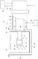
図1は、本発明の一実施形態に係るクライオポンプ10を模式的に示す図である。クライオポンプ10は、例えばイオン注入装置やスパッタリング装置等の真空チャンバに取り付けられて、真空チャンバ内部の真空度を所望のプロセスに要求されるレベルまで高めるために使用される。クライオポンプ10は、クライオポンプ容器30と、放射シールド40と、冷凍機50と、を含んで構成される。   FIG. 1 is a diagram schematically illustrating a cryopump 10 according to an embodiment of the present invention. The cryopump 10 is attached to a vacuum chamber such as an ion implantation apparatus or a sputtering apparatus, and is used to increase the degree of vacuum inside the vacuum chamber to a level required for a desired process. The cryopump 10 includes a cryopump container 30, a radiation shield 40, and a refrigerator 50.

冷凍機50は、例えばギフォード・マクマホン式冷凍機(いわゆるGM冷凍機)などの冷凍機である。冷凍機50は、第1シリンダ11、第2シリンダ12、第1冷却ステージ13、第2冷却ステージ14、バルブ駆動モータ16を備える。第1シリンダ11と第2シリンダ12は直列に接続される。第1シリンダ11の第2シリンダ12との結合部側には第1冷却ステージ13が設置され、第2シリンダ12の第1シリンダ11から遠い側の端には第2冷却ステージ14が設置される。   The refrigerator 50 is a refrigerator such as a Gifford McMahon refrigerator (so-called GM refrigerator). The refrigerator 50 includes a first cylinder 11, a second cylinder 12, a first cooling stage 13, a second cooling stage 14, and a valve drive motor 16. The first cylinder 11 and the second cylinder 12 are connected in series. A first cooling stage 13 is installed on the side of the first cylinder 11 where the second cylinder 12 is joined, and a second cooling stage 14 is installed on the end of the second cylinder 12 far from the first cylinder 11. .

図1に示す冷凍機50は、二段式の冷凍機であり、シリンダを直列に二段組み合わせてより低い温度を達成している。冷凍機50は、三段のシリンダが直列に接続される三段式の冷凍機またはそれよりも多段の冷凍機であってもよい。冷凍機50は冷媒管18を介して圧縮機52に接続される。   The refrigerator 50 shown in FIG. 1 is a two-stage refrigerator, and achieves a lower temperature by combining two stages of cylinders in series. The refrigerator 50 may be a three-stage refrigerator in which three-stage cylinders are connected in series or a multistage refrigerator. The refrigerator 50 is connected to the compressor 52 through the refrigerant pipe 18.

圧縮機52は、例えばヘリウム等の冷媒ガス、すなわち作動気体を圧縮して、冷媒管18を介して冷凍機50に供給する。冷凍機50は、作動気体を蓄冷器を通過させることにより冷却する。第1シリンダ11の内部の膨張室で、及び第2シリンダ12の内部の膨張室で膨張させて作動気体をさらに冷却する。蓄冷器は膨張室内部に組み込まれている。第1シリンダ11に設置される第1冷却ステージ13は第1の冷却温度レベルに冷却され、第2シリンダ12に設置される第2冷却ステージ14は第1の冷却温度レベルよりも低温の第2の冷却温度レベルに冷却される。例えば、第1冷却ステージ13は65K〜120K程度、好ましくは80K〜100Kに冷却され、第2冷却ステージ14は10K〜20K程度に冷却される。   The compressor 52 compresses a refrigerant gas such as helium, that is, a working gas, and supplies the compressed gas to the refrigerator 50 through the refrigerant pipe 18. The refrigerator 50 cools the working gas by passing it through the regenerator. The working gas is further cooled by being expanded in the expansion chamber inside the first cylinder 11 and in the expansion chamber inside the second cylinder 12. The regenerator is incorporated in the expansion chamber. The first cooling stage 13 installed in the first cylinder 11 is cooled to the first cooling temperature level, and the second cooling stage 14 installed in the second cylinder 12 is a second lower temperature than the first cooling temperature level. Cooled to the cooling temperature level. For example, the first cooling stage 13 is cooled to about 65K to 120K, preferably 80K to 100K, and the second cooling stage 14 is cooled to about 10K to 20K.

こうして冷凍機50は、低温クライオパネルを冷却するための低温冷却位置と高温クライオパネルを冷却するための高温冷却位置とを提供する。低温冷却位置と高温冷却位置とが長手方向すなわちシリンダ配列方向に配列されている。中間の冷却温度を提供する1つまたは複数の中間冷却位置が低温冷却位置と高温冷却位置との間に配列されていてもよい。   Thus, the refrigerator 50 provides a low temperature cooling position for cooling the low temperature cryopanel and a high temperature cooling position for cooling the high temperature cryopanel. The low-temperature cooling position and the high-temperature cooling position are arranged in the longitudinal direction, that is, the cylinder arrangement direction. One or more intermediate cooling positions providing an intermediate cooling temperature may be arranged between the cold cooling position and the hot cooling position.

膨張室で膨張することで吸熱し、各冷却ステージを冷却した作動気体は、再び蓄冷器を通過し、冷媒管18を経て圧縮機52に戻される。圧縮機52から冷凍機50へ、また冷凍機50から圧縮機52への作動気体の流れは、冷凍機50内のロータリバルブ(図示せず)により切り替えられる。バルブ駆動モータ16は、外部電源から電力の供給を受けて、ロータリバルブを回転させる。   The working gas that has absorbed heat by expanding in the expansion chamber and has cooled each cooling stage again passes through the regenerator, and is returned to the compressor 52 through the refrigerant pipe 18. The flow of the working gas from the compressor 52 to the refrigerator 50 and from the refrigerator 50 to the compressor 52 is switched by a rotary valve (not shown) in the refrigerator 50. The valve drive motor 16 receives power supplied from an external power source and rotates the rotary valve.

冷凍機50を制御するための制御部20が設けられている。制御部20は、第1冷却ステージ13または第2冷却ステージ14の冷却温度に基づいて冷凍機50を制御する。そのために、第1冷却ステージ13または第2冷却ステージ14に温度センサ28が設けられていてもよい。制御部20は、バルブ駆動モータ16の運転周波数を制御することにより冷却温度を制御してもよい。そのために制御部20は、バルブ駆動モータ16を制御するためのインバータを備えてもよい。制御部20は圧縮機52を制御するよう構成されていてもよい。制御部20はクライオポンプ10に一体に設けられていてもよいし、クライオポンプ10とは別体の制御装置として構成されていてもよい。   A control unit 20 for controlling the refrigerator 50 is provided. The control unit 20 controls the refrigerator 50 based on the cooling temperature of the first cooling stage 13 or the second cooling stage 14. Therefore, a temperature sensor 28 may be provided in the first cooling stage 13 or the second cooling stage 14. The control unit 20 may control the cooling temperature by controlling the operating frequency of the valve drive motor 16. Therefore, the control unit 20 may include an inverter for controlling the valve drive motor 16. The control unit 20 may be configured to control the compressor 52. The control unit 20 may be provided integrally with the cryopump 10 or may be configured as a separate control device from the cryopump 10.

図1に示されるクライオポンプ10は、いわゆる横型のクライオポンプである。横型のクライオポンプとは一般に、冷凍機の第2冷却ステージ14が筒状の放射シールド40の軸方向に交差する方向(通常は直交方向)に沿って放射シールド40の内部に挿入されているクライオポンプである。なお、本発明はいわゆる縦型のクライオポンプにも同様に適用することができる。縦型のクライオポンプとは、放射シールドの軸方向に沿って冷凍機が挿入されているクライオポンプである。   A cryopump 10 shown in FIG. 1 is a so-called horizontal cryopump. In general, a horizontal cryopump is a cryocooler in which the second cooling stage 14 of the refrigerator is inserted into the radiation shield 40 along a direction (usually an orthogonal direction) intersecting the axial direction of the cylindrical radiation shield 40. It is a pump. The present invention can be similarly applied to a so-called vertical cryopump. A vertical cryopump is a cryopump in which a refrigerator is inserted along the axial direction of the radiation shield.

クライオポンプ容器30は、一端に開口を有し他端が閉塞されている円筒状の形状に形成された部位(以下、「胴部」と呼ぶ)32を有する。開口は、スパッタ装置等の真空チャンバから排気されるべき気体が進入する吸気口34として、設けられている。吸気口34はクライオポンプ容器30の胴部32の上端部内面により画定される。また胴部32には冷凍機50を挿通するための開口37が形成されている。胴部32の開口37には円筒状の冷凍機収容部38の一端が取り付けられ、他端は冷凍機50のハウジングに取り付けられている。冷凍機収容部38は冷凍機50の第1シリンダ11を収容する。   The cryopump container 30 has a portion (hereinafter referred to as a “body portion”) 32 formed in a cylindrical shape having an opening at one end and the other end closed. The opening is provided as an intake port 34 through which a gas to be exhausted from a vacuum chamber such as a sputtering apparatus enters. The air inlet 34 is defined by the inner surface of the upper end portion of the body portion 32 of the cryopump container 30. Further, an opening 37 for inserting the refrigerator 50 is formed in the body portion 32. One end of a cylindrical refrigerator housing portion 38 is attached to the opening 37 of the body portion 32, and the other end is attached to the housing of the refrigerator 50. The refrigerator accommodating portion 38 accommodates the first cylinder 11 of the refrigerator 50.

またクライオポンプ容器30の胴部32の上端には径方向外側に向けて取付フランジ36が延びている。クライオポンプ10は、排気対象容積であるスパッタ装置等の真空チャンバに、取付フランジ36を用いて取り付けられる。   A mounting flange 36 extends radially outward from the upper end of the body 32 of the cryopump container 30. The cryopump 10 is attached using a mounting flange 36 to a vacuum chamber such as a sputtering apparatus that is a volume to be exhausted.

クライオポンプ容器30は、クライオポンプ10の内部と外部とを隔てるために設けられている。上述のようにクライオポンプ容器30は胴部32と冷凍機収容部38とを含んで構成されており、胴部32及び冷凍機収容部38の内部は共通の圧力に気密に保持される。クライオポンプ容器30の外面は、クライオポンプ10の動作中、すなわち冷凍機が作動している間も、クライオポンプ10の外部の環境にさらされる。そのため、クライオポンプ容器30の外面は放射シールド40よりも高い温度に維持される。典型的にはクライオポンプ容器30の温度は環境温度に維持される。ここで環境温度とは、クライオポンプ10が設置されている場所の温度、またはその温度に近い温度をいい、例えば室温程度である。   The cryopump container 30 is provided to separate the inside and the outside of the cryopump 10. As described above, the cryopump container 30 is configured to include the body portion 32 and the refrigerator housing portion 38, and the inside of the body portion 32 and the refrigerator housing portion 38 is kept airtight at a common pressure. The outer surface of the cryopump container 30 is exposed to the environment outside the cryopump 10 during operation of the cryopump 10, that is, while the refrigerator is operating. Therefore, the outer surface of the cryopump container 30 is maintained at a temperature higher than that of the radiation shield 40. Typically, the temperature of the cryopump container 30 is maintained at the ambient temperature. Here, the environmental temperature refers to a temperature at a location where the cryopump 10 is installed or a temperature close to the temperature, for example, about room temperature.

放射シールド40は、クライオポンプ容器30の内部に配設されている。放射シールド40は、一端に開口を有し他端が閉塞されている円筒状の形状、すなわちカップ状の形状に形成されている。放射シールド40は、図1に示されるような一体の筒状に構成されていてもよく、また、複数のパーツにより全体として筒状の形状をなすように構成されていてもよい。これら複数のパーツは互いに間隙を有して配設されていてもよい。   The radiation shield 40 is disposed inside the cryopump container 30. The radiation shield 40 is formed in a cylindrical shape having an opening at one end and closed at the other end, that is, a cup shape. The radiation shield 40 may be configured in an integral cylindrical shape as shown in FIG. 1 or may be configured so as to form a cylindrical shape as a whole by a plurality of parts. The plurality of parts may be arranged with a gap therebetween.

クライオポンプ容器30の胴部32及び放射シールド40はともに略円筒状に形成されており、同軸に配設されている。クライオポンプ容器30の胴部32の内径が放射シールド40の外径を若干上回っており、放射シールド40はクライオポンプ容器30の胴部32の内面との間に若干の間隔をもってクライオポンプ容器30とは非接触の状態で配置される。すなわち、放射シールド40の外面は、クライオポンプ容器30の内面と対向している。なお、クライオポンプ容器30の胴部32および放射シールド40の形状は、円筒形状には限られず、角筒形状や楕円筒形状などいかなる断面の筒形状でもよい。典型的には、放射シールド40の形状はクライオポンプ容器30の胴部32の内面形状に相似する形状とされる。   Both the body 32 and the radiation shield 40 of the cryopump container 30 are formed in a substantially cylindrical shape and are arranged coaxially. The inner diameter of the body portion 32 of the cryopump container 30 is slightly larger than the outer diameter of the radiation shield 40, and the radiation shield 40 is slightly spaced from the inner surface of the body section 32 of the cryopump container 30 with the cryopump container 30. Are arranged in a non-contact state. That is, the outer surface of the radiation shield 40 faces the inner surface of the cryopump container 30. Note that the shapes of the body portion 32 and the radiation shield 40 of the cryopump container 30 are not limited to a cylindrical shape, and may be a cylindrical shape having any cross section such as a rectangular cylindrical shape or an elliptical cylindrical shape. Typically, the shape of the radiation shield 40 is similar to the shape of the inner surface of the body portion 32 of the cryopump container 30.

放射シールド40は、第2冷却ステージ14およびこれに熱的に接続される低温クライオパネル60を主にクライオポンプ容器30からの輻射熱から保護する高温クライオパネルとして設けられている。放射シールド40は、低温クライオパネル60を包囲する。第2冷却ステージ14は、放射シールド40の内部において放射シールド40のほぼ中心軸上に配置される。放射シールド40は、第1冷却ステージ13に熱的に接続された状態で固定され、第1冷却ステージ13と同程度の温度に冷却される。   The radiation shield 40 is provided as a high-temperature cryopanel that mainly protects the second cooling stage 14 and the low-temperature cryopanel 60 that is thermally connected thereto from radiation heat from the cryopump container 30. The radiation shield 40 surrounds the low-temperature cryopanel 60. The second cooling stage 14 is disposed substantially on the central axis of the radiation shield 40 inside the radiation shield 40. The radiation shield 40 is fixed in a state where it is thermally connected to the first cooling stage 13, and is cooled to a temperature comparable to that of the first cooling stage 13.

低温クライオパネル60は、例えば複数のパネル64を含む。パネル64は例えば、それぞれが円すい台の側面の形状、いわば傘状の形状を有する。各パネル64は、第2冷却ステージ14に取り付けられているパネル取付部材66に取り付けられている。各パネル64には通常活性炭等の吸着剤(図示せず)が設けられている。吸着剤は例えばパネル64の裏面に接着されている。   The low-temperature cryopanel 60 includes a plurality of panels 64, for example. For example, each of the panels 64 has a shape of a side surface of a truncated cone, that is, an umbrella-like shape. Each panel 64 is attached to a panel attachment member 66 attached to the second cooling stage 14. Each panel 64 is usually provided with an adsorbent (not shown) such as activated carbon. For example, the adsorbent is bonded to the back surface of the panel 64.

パネル取付部材66は例えば、一端が閉塞され他端が開放されている筒形状を有し、閉塞された端部が第2冷却ステージ14の上端に取り付けられ、筒状側面が第2冷却ステージ14を取り囲むように放射シールド40の底部に向けて延びている。パネル取付部材66の側面に複数のパネル64が互いに間隔をあけて取り付けられている。パネル取付部材66の側面には、冷凍機50の第2シリンダ12を通すための開口が形成されている。あるいは、パネル取付部材66は、第2冷却ステージ14への取付のための端部と、その端部から放射シールド40の底部に向けて延びるパネル取付のための平板と、を備えてもよい。   The panel attachment member 66 has, for example, a cylindrical shape in which one end is closed and the other end is open, the closed end is attached to the upper end of the second cooling stage 14, and the cylindrical side surface is the second cooling stage 14. Is extended toward the bottom of the radiation shield 40. A plurality of panels 64 are attached to the side surface of the panel attachment member 66 at intervals. An opening for passing the second cylinder 12 of the refrigerator 50 is formed on the side surface of the panel mounting member 66. Alternatively, the panel attachment member 66 may include an end portion for attachment to the second cooling stage 14 and a flat plate for panel attachment extending from the end portion toward the bottom of the radiation shield 40.

放射シールド40の吸気口には、真空チャンバ等からの輻射熱から第2冷却ステージ14およびこれに熱的に接続される低温クライオパネル60を保護するために、バッフル62が設けられている。バッフル62は、例えば、ルーバ構造やシェブロン構造に形成される。バッフル62は、放射シールド40の中心軸を中心とする同心円状に形成されていてもよいし、あるいは格子状等他の形状に形成されていてもよい。バッフル62は放射シールド40の開口側の端部に取り付けられており、放射シールド40と同程度の温度に冷却される。なおバッフル62と真空チャンバとの間にはゲートバルブ(図示せず)が設けられていてもよい。このゲートバルブは例えばクライオポンプ10を再生するときに閉とされ、クライオポンプ10により真空チャンバを排気するときに開とされる。   A baffle 62 is provided at the intake port of the radiation shield 40 in order to protect the second cooling stage 14 and the low-temperature cryopanel 60 thermally connected thereto from radiant heat from a vacuum chamber or the like. The baffle 62 is formed in a louver structure or a chevron structure, for example. The baffle 62 may be formed concentrically around the central axis of the radiation shield 40, or may be formed in another shape such as a lattice shape. The baffle 62 is attached to the end of the radiation shield 40 on the opening side, and is cooled to a temperature similar to that of the radiation shield 40. A gate valve (not shown) may be provided between the baffle 62 and the vacuum chamber. This gate valve is closed when, for example, the cryopump 10 is regenerated, and is opened when the vacuum chamber is evacuated by the cryopump 10.

放射シールド40の側面には冷凍機取付孔42が形成されている。冷凍機取付孔42は、放射シールド40の中心軸方向に関して放射シールド40側面の中央部に形成されている。放射シールド40の冷凍機取付孔42はクライオポンプ容器30の開口37と同軸に設けられている。冷凍機50の第2シリンダ12及び第2冷却ステージ14は冷凍機取付孔42から放射シールド40の中心軸方向に垂直な方向に沿って挿入されている。放射シールド40は、冷凍機取付孔42において第1冷却ステージ13に熱的に接続された状態で固定される。   A refrigerator mounting hole 42 is formed on the side surface of the radiation shield 40. The refrigerator mounting hole 42 is formed in the center of the side surface of the radiation shield 40 with respect to the central axis direction of the radiation shield 40. The refrigerator mounting hole 42 of the radiation shield 40 is provided coaxially with the opening 37 of the cryopump container 30. The second cylinder 12 and the second cooling stage 14 of the refrigerator 50 are inserted from the refrigerator attachment hole 42 along a direction perpendicular to the central axis direction of the radiation shield 40. The radiation shield 40 is fixed in a state where it is thermally connected to the first cooling stage 13 in the refrigerator mounting hole 42.

なお放射シールド40が第1冷却ステージ13に直接取り付けられる代わりに、接続用のスリーブによって放射シールド40が第1冷却ステージ13に取り付けられてもよい。このスリーブは例えば、第2シリンダ12の第1冷却ステージ13側の端部を包囲し、放射シールド40を第1冷却ステージ13に熱的に接続するための伝熱部材である。この構成により、放射シールド40を第1冷却ステージ13に直接取り付ける場合に比べて、第2シリンダ12を長くすることができる。第1冷却ステージ13と第2冷却ステージ14との温度差を大きくすることができる。   Instead of directly attaching the radiation shield 40 to the first cooling stage 13, the radiation shield 40 may be attached to the first cooling stage 13 by a connecting sleeve. This sleeve is, for example, a heat transfer member that surrounds the end of the second cylinder 12 on the first cooling stage 13 side and thermally connects the radiation shield 40 to the first cooling stage 13. With this configuration, the second cylinder 12 can be made longer than when the radiation shield 40 is directly attached to the first cooling stage 13. The temperature difference between the first cooling stage 13 and the second cooling stage 14 can be increased.

上記の構成のクライオポンプ10による動作を以下に説明する。クライオポンプ10の作動に際しては、まずその作動前に他の適当な粗引きポンプで真空チャンバ内部を1Pa程度にまで粗引きする。その後クライオポンプ10を作動させる。冷凍機50の駆動により第1冷却ステージ13及び第2冷却ステージ14が冷却され、これらに熱的に接続されている放射シールド40、バッフル62、クライオパネル60も冷却される。   The operation of the cryopump 10 having the above configuration will be described below. When the cryopump 10 is operated, the vacuum chamber is first roughed to about 1 Pa with another appropriate roughing pump before the operation. Thereafter, the cryopump 10 is operated. The first cooling stage 13 and the second cooling stage 14 are cooled by driving the refrigerator 50, and the radiation shield 40, the baffle 62, and the cryopanel 60 that are thermally connected to the first cooling stage 13 and the second cooling stage 14 are also cooled.

冷却されたバッフル62は、真空チャンバからクライオポンプ10内部へ向かって飛来する気体分子を冷却し、その冷却温度で蒸気圧が充分に低くなる気体(例えば水分など)を表面に凝縮させて排気する。バッフル62の冷却温度では蒸気圧が充分に低くならない気体はバッフル62を通過して放射シールド40内部へと進入する。進入した気体分子のうちクライオパネル60の冷却温度で蒸気圧が充分に低くなる気体は、クライオパネル60の表面に凝縮されて排気される。その冷却温度でも蒸気圧が充分に低くならない気体(例えば水素など)は、クライオパネル60の表面に接着され冷却されている吸着剤により吸着されて排気される。このようにしてクライオポンプ10は真空チャンバの真空度を所望のレベルに到達させることができる。   The cooled baffle 62 cools gas molecules flying from the vacuum chamber toward the inside of the cryopump 10, and condenses and exhausts a gas (for example, moisture) whose vapor pressure is sufficiently low at the cooling temperature. . The gas whose vapor pressure does not become sufficiently low at the cooling temperature of the baffle 62 passes through the baffle 62 and enters the radiation shield 40. Of the gas molecules that have entered, the gas whose vapor pressure is sufficiently low at the cooling temperature of the cryopanel 60 is condensed on the surface of the cryopanel 60 and exhausted. A gas (for example, hydrogen) whose vapor pressure does not become sufficiently low even at the cooling temperature is adsorbed and exhausted by an adsorbent that is bonded to the surface of the cryopanel 60 and cooled. In this manner, the cryopump 10 can reach the desired vacuum level in the vacuum chamber.

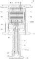
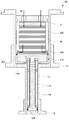
図2乃至図4は、本発明の一実施形態に係る冷凍機50の要部を示す図である。それぞれ冷凍機50の中心軸を含む断面を示す。図3は吸気工程における作動気体流れを矢印で模式的に示し、図4は排気工程における作動気体流れを矢印で模式的に示す。   2 to 4 are views showing the main part of the refrigerator 50 according to one embodiment of the present invention. A cross section including the central axis of the refrigerator 50 is shown. FIG. 3 schematically shows the working gas flow in the intake process with arrows, and FIG. 4 schematically shows the working gas flow in the exhaust process with arrows.

冷凍機50は、中心軸方向すなわち長手方向に沿って互いに隣接する第1ディスプレーサ68及び第2ディスプレーサ70を備える。高温側の第1ディスプレーサ68と低温側の第2ディスプレーサ70とは連結部72により連結される。冷凍機50は、第2ディスプレーサ70の高温側の末端(図において上端)が第1ディスプレーサ68の低温端にいくらか入り込んで連結されるディスプレーサ連結構造を備える。   The refrigerator 50 includes a first displacer 68 and a second displacer 70 that are adjacent to each other along the central axis direction, that is, the longitudinal direction. The first displacer 68 on the high temperature side and the second displacer 70 on the low temperature side are connected by a connecting portion 72. The refrigerator 50 includes a displacer connection structure in which the end of the second displacer 70 on the high temperature side (the upper end in the figure) is somewhat inserted into and connected to the low temperature end of the first displacer 68.

詳しくは後述するように、第1ディスプレーサ68は、第1蓄冷器88を備える。第1蓄冷器88は、高温側から流入する作動気体を冷却して低温側に送出するための冷却経路を含む。第1蓄冷器88は、高温側のディスプレーサに好適な蓄冷材86と、その蓄冷材86のための蓄冷材容器87と、を備える。第1蓄冷器88は、主蓄冷器134と副蓄冷器136とに区分することができる。第1ディスプレーサ68から主蓄冷器134及び副蓄冷器136を通じて第2蓄冷器114へ向けて作動気体を案内する直通流路が形成されている。副蓄冷器136を設けることにより、第1蓄冷器88は、第1膨張空間94に作動気体を送出するための冷却経路よりも、第2蓄冷器114に作動気体を送出するための冷却経路が長くなる。   As will be described in detail later, the first displacer 68 includes a first regenerator 88. The first regenerator 88 includes a cooling path for cooling the working gas flowing from the high temperature side and sending it to the low temperature side. The first regenerator 88 includes a cool storage material 86 suitable for a displacer on the high temperature side, and a cool storage material container 87 for the cool storage material 86. The first regenerator 88 can be divided into a main regenerator 134 and a sub regenerator 136. A direct flow path for guiding the working gas from the first displacer 68 to the second regenerator 114 through the main regenerator 134 and the sub regenerator 136 is formed. By providing the auxiliary regenerator 136, the first regenerator 88 has a cooling path for sending the working gas to the second regenerator 114 rather than a cooling path for sending the working gas to the first expansion space 94. become longer.

第1ディスプレーサ68の中空構造が蓄冷材容器87を兼ねている。蓄冷材容器87は、蓄冷材86を充填するための主収容区画138と副収容区画140とを含む。主収容区画138に主蓄冷器134が収容され、副収容区画140に副蓄冷器136が収容される。副収容区画140は、主収容区画138の低温側に主収容区画138と気体流通可能に設けられている。副収容区画140は、長手方向に垂直な断面積が主収容区画138よりも小さい。それによって、主蓄冷器134から第1膨張空間94へ向けて作動気体を案内する独立流路を、副収容区画140の外側に直通流路から隔てて形成することができる。   The hollow structure of the first displacer 68 also serves as the cool storage material container 87. The cool storage material container 87 includes a main storage section 138 and a sub storage section 140 for filling the cool storage material 86. The main regenerator 134 is accommodated in the main accommodating section 138, and the sub regenerator 136 is accommodated in the sub accommodating section 140. The sub-accommodating compartment 140 is provided on the low temperature side of the main accommodating compartment 138 so as to allow gas to flow with the main accommodating compartment 138. The sub-accommodating section 140 has a cross-sectional area perpendicular to the longitudinal direction that is smaller than the main accommodating section 138. Thereby, an independent flow path for guiding the working gas from the main regenerator 134 toward the first expansion space 94 can be formed outside the sub-accommodating section 140 and separated from the direct flow path.

第1シリンダ11と第2シリンダ12とは一体に形成されており、第1シリンダ11の低温端と第2シリンダ12の高温端とが第1シリンダ底部74により接続されている。第1シリンダ11及び第2シリンダ12はそれぞれ長手方向に直列に並んでいる。第2シリンダ12は第1シリンダ11と同軸に配置され、第1シリンダ11よりも小径の円筒部材である。第1シリンダ11は第1ディスプレーサ68を往復動可能に収容し、第2シリンダ12は第2ディスプレーサ70を往復動可能に収容する。   The first cylinder 11 and the second cylinder 12 are integrally formed, and the low temperature end of the first cylinder 11 and the high temperature end of the second cylinder 12 are connected by a first cylinder bottom 74. The first cylinder 11 and the second cylinder 12 are arranged in series in the longitudinal direction. The second cylinder 12 is disposed coaxially with the first cylinder 11 and is a cylindrical member having a smaller diameter than the first cylinder 11. The 1st cylinder 11 accommodates the 1st displacer 68 so that reciprocation is possible, and the 2nd cylinder 12 accommodates the 2nd displacer 70 so that reciprocation is possible.

第1シリンダ11の低温端の外周部に第1冷却ステージ13が取り付けられ、第2シリンダ12の低温端の外周部に第2冷却ステージ14が取り付けられている。第1シリンダ底部74は第1シリンダ11と第2シリンダ12とを各々の末端で接続する円環状の部材である。第2シリンダ12の低温端は第2シリンダ底部76で閉塞されている。第1シリンダ11の高温端の外周部にはフランジ部78が形成されている。   A first cooling stage 13 is attached to the outer periphery of the low temperature end of the first cylinder 11, and a second cooling stage 14 is attached to the outer periphery of the low temperature end of the second cylinder 12. The first cylinder bottom 74 is an annular member that connects the first cylinder 11 and the second cylinder 12 at their respective ends. The low temperature end of the second cylinder 12 is closed by the second cylinder bottom 76. A flange portion 78 is formed on the outer periphery of the high temperature end of the first cylinder 11.

第1シリンダ11の高温端に隣接して、バルブ駆動モータ16やロータリバルブ、スコッチヨーク機構を備える駆動機構(図示せず)が設けられている。第1ディスプレーサ68は、スコッチヨーク機構に接続されている。このスコッチヨーク機構は、バルブ駆動モータ16により駆動される。モータの回転はスコッチヨーク機構により直線往復運動に変換され、これにより第1ディスプレーサ68は第1シリンダ11の内側面に沿って往復移動する。第1ディスプレーサ68と第2ディスプレーサ70とは連結されているため、第1ディスプレーサ68に連動して第2ディスプレーサ70も第2シリンダ12の内側面に沿って往復移動する。   A drive mechanism (not shown) including a valve drive motor 16, a rotary valve, and a scotch yoke mechanism is provided adjacent to the high temperature end of the first cylinder 11. The first displacer 68 is connected to the scotch yoke mechanism. This scotch yoke mechanism is driven by a valve drive motor 16. The rotation of the motor is converted into a linear reciprocating motion by the Scotch yoke mechanism, whereby the first displacer 68 reciprocates along the inner surface of the first cylinder 11. Since the first displacer 68 and the second displacer 70 are connected, the second displacer 70 also reciprocates along the inner surface of the second cylinder 12 in conjunction with the first displacer 68.

第1ディスプレーサ68は、第1シリンダ11の内部容積形状に対応して概ね円筒状に形成されている部材である。第1ディスプレーサ68の最も大径の部分の外径は第1シリンダ11の内径に実質的に等しいかわずかに小さいことにより、第1ディスプレーサ68は第1シリンダ11に沿って摺動可能または微小間隙を有して非接触に移動可能である。   The first displacer 68 is a member that is formed in a substantially cylindrical shape corresponding to the internal volume shape of the first cylinder 11. Since the outer diameter of the largest diameter portion of the first displacer 68 is substantially equal to or slightly smaller than the inner diameter of the first cylinder 11, the first displacer 68 can slide along the first cylinder 11 or have a minute gap. And can be moved in a non-contact manner.

第1ディスプレーサ68は、第1高温端80、第1円筒部分82、及び第1低温端84とを含んで構成される。第1高温端80及び第1低温端84はそれぞれ第1円筒部分82の互いに対向する端面を閉塞する。後述するように、第1ディスプレーサ68の内部と外部とを接続するための開口が第1高温端80及び第1低温端84のそれぞれに形成されている。   The first displacer 68 includes a first high temperature end 80, a first cylindrical portion 82, and a first low temperature end 84. The first high temperature end 80 and the first low temperature end 84 close the end surfaces of the first cylindrical portion 82 facing each other. As will be described later, openings for connecting the inside and the outside of the first displacer 68 are formed in each of the first high temperature end 80 and the first low temperature end 84.

第1ディスプレーサ68の第1高温端80と第1円筒部分82との接続部の径方向外側にシールを装着するための円環溝が形成されており、そこに円環状の第1シール90が装着されている。第1シール90は第1シリンダ11に摺動可能に密着し、第1ディスプレーサ68の外側での第1シリンダ11の高温端と第1膨張空間94との間の作動気体の流通を遮断する。第1ディスプレーサ68の第1円筒部分82の外周部分には極浅い凹部92がシリンダ外部との断熱性を高めるために形成されている。   An annular groove for mounting a seal is formed on the radially outer side of the connecting portion between the first high temperature end 80 and the first cylindrical portion 82 of the first displacer 68, and an annular first seal 90 is formed there. It is installed. The first seal 90 is slidably in close contact with the first cylinder 11 and blocks the flow of working gas between the high temperature end of the first cylinder 11 and the first expansion space 94 outside the first displacer 68. An extremely shallow recess 92 is formed in the outer peripheral portion of the first cylindrical portion 82 of the first displacer 68 in order to enhance the heat insulation from the outside of the cylinder.

第1円筒部分82の内部に第1段の蓄冷材86が充填されている。蓄冷材86は例えば、金属(例えば銅、または銅と他の金属例えば亜鉛との合金)の金網の積層体である。または蓄冷材86はこうした金属製の多数の開口を有するプレートの積層体であってもよい。第1高温端80、第1円筒部分82、及び第1低温端84に囲まれた第1ディスプレーサ68の内部容積は、蓄冷材86を保持する第1蓄冷器88であるとも言える。   The first cylindrical portion 82 is filled with a first-stage cold storage material 86. The regenerator material 86 is, for example, a metal mesh laminate of metal (for example, copper or an alloy of copper and another metal such as zinc). Alternatively, the regenerator material 86 may be a laminated body of plates having many openings made of such metal. It can be said that the internal volume of the first displacer 68 surrounded by the first high temperature end 80, the first cylindrical portion 82, and the first low temperature end 84 is the first regenerator 88 that holds the regenerator material 86.

第1ディスプレーサ68はその内部に、主収容区画138と副収容区画140とを画定する。主収容区画138は第1高温端80、第1円筒部分82、及び第1低温端84に囲まれており、第1ディスプレーサ68の容積の大半を占める。副収容区画140は、主収容区画138の低温側に連続する空間であり、第1低温端84に形成されている。副収容区画140は、主収容区画138を第1ディスプレーサ68の外側に接続する単一の開口部分であってもよいし、複数の開口であってもよい。   The first displacer 68 defines a main storage compartment 138 and a secondary storage compartment 140 therein. The main receiving compartment 138 is surrounded by the first hot end 80, the first cylindrical portion 82, and the first cold end 84 and occupies most of the volume of the first displacer 68. The sub-accommodating section 140 is a space continuous on the low temperature side of the main accommodating section 138 and is formed at the first low-temperature end 84. The sub housing section 140 may be a single opening portion that connects the main housing section 138 to the outside of the first displacer 68, or may be a plurality of openings.

主収容区画138は大径の円筒空間であり、副収容区画140はそれよりも小径の円筒空間である。主収容区画138と副収容区画140とは同軸に配列されており、主収容区画138の低温側の中心部に副収容区画140がつながっている。副収容区画140は、第1ディスプレーサ68に第2ディスプレーサ70を受け入れるための凹部132の少なくとも一部であり、例えば、凹部132のうちコネクタ部材128と主収容区画138との間の領域である。   The main accommodating section 138 is a large-diameter cylindrical space, and the sub-accommodating section 140 is a smaller-diameter cylindrical space. The main housing section 138 and the sub housing section 140 are arranged coaxially, and the sub housing section 140 is connected to the center of the main housing section 138 on the low temperature side. The sub-accommodating section 140 is at least a part of the recess 132 for receiving the second displacer 70 in the first displacer 68. For example, the sub-accommodating section 140 is an area between the connector member 128 and the main accommodating section 138 in the recess 132.

同種の蓄冷材86が主収容区画138と副収容区画140の両方に充填されている。主収容区画138に充填されている蓄冷材86が主蓄冷器134を構成し、副収容区画140に充填されている蓄冷材86が副蓄冷器136を構成する。副蓄冷器136は、主蓄冷器134から第2ディスプレーサ70に向けて凹部132を延びる蓄冷材延長部分である。すなわち、第1ディスプレーサ68は、第1低温端84に蓄冷材延長部分を備える。   The same type of regenerator material 86 is filled in both the main housing section 138 and the sub housing section 140. The regenerator material 86 filled in the main housing section 138 constitutes the main regenerator 134, and the regenerator material 86 filled in the sub housing section 140 constitutes the sub regenerator 136. The sub regenerator 136 is a regenerative material extension portion that extends from the main regenerator 134 toward the second displacer 70 and extends through the recess 132. That is, the first displacer 68 includes a cold storage material extension portion at the first low temperature end 84.

副蓄冷器136の蓄冷材は、例えば凹部132の内壁から突き出す押さえ部(図示せず)によって副収容区画140に保持されていてもよい。あるいは、副蓄冷器136の蓄冷材は、連結部72のコネクタ部材128の上端によって、副収容区画140に保持されていてもよい。   The regenerator material of the sub-regenerator 136 may be held in the sub-accommodating section 140 by a pressing portion (not shown) protruding from the inner wall of the recess 132, for example. Alternatively, the regenerator material of the sub regenerator 136 may be held in the sub housing section 140 by the upper end of the connector member 128 of the connecting portion 72.

主収容区画138と副収容区画140とで異種の蓄冷材が充填されていてもよい。あるいは、主収容区画138と副収容区画140との少なくとも一方が更に、異種の蓄冷材のための複数の小区画に区分されていてもよい。この場合、主収容区画138と副収容区画140との境界、または隣り合う小区画の境界には、異種の蓄冷材を仕切るための仕切部材または空隙が設けられていてもよい。   Different main storage compartments 138 and sub-accommodation compartments 140 may be filled with different kinds of cold storage materials. Alternatively, at least one of the main storage section 138 and the sub storage section 140 may be further divided into a plurality of small sections for different kinds of cold storage materials. In this case, a partition member or a gap for partitioning different kinds of cold storage materials may be provided at the boundary between the main storage section 138 and the sub storage section 140 or the boundary between adjacent small sections.

第1低温端84に隣接して、第1シリンダ11の内部には第1膨張空間94が形成されている。第1膨張空間94は第1ディスプレーサ68の往復運動により容積が変化する。第1膨張空間94は、第1ディスプレーサ68、第1シリンダ11、及び第2ディスプレーサ70で囲まれる領域である。具体的には、第1膨張空間94は、第1ディスプレーサ68の第1低温端84と、第1シリンダ11の内面と、第1ディスプレーサ68の凹部132から延びている第2ディスプレーサ70の第2円筒部分108と、により画定される。第1膨張空間94と第1低温端84の末端部とが第2ディスプレーサ70の高温端106を取り巻いている。   A first expansion space 94 is formed in the first cylinder 11 adjacent to the first low temperature end 84. The volume of the first expansion space 94 changes as the first displacer 68 reciprocates. The first expansion space 94 is an area surrounded by the first displacer 68, the first cylinder 11, and the second displacer 70. Specifically, the first expansion space 94 includes a second low temperature end 84 of the first displacer 68, an inner surface of the first cylinder 11, and a second of the second displacer 70 extending from the recess 132 of the first displacer 68. Defined by a cylindrical portion 108. The first expansion space 94 and the end of the first low temperature end 84 surround the high temperature end 106 of the second displacer 70.

第1ディスプレーサ68の第1高温端80には、第1ディスプレーサ68の外側(すなわち第1シリンダ11の高温側)と第1蓄冷器88との間で作動気体を流通させるための第1開口96が形成されている。第1開口96は、中心軸を取り巻く周方向に沿って複数箇所に設けられている。   The first high temperature end 80 of the first displacer 68 has a first opening 96 for allowing working gas to flow between the outside of the first displacer 68 (that is, the high temperature side of the first cylinder 11) and the first regenerator 88. Is formed. The first openings 96 are provided at a plurality of locations along the circumferential direction surrounding the central axis.

第1ディスプレーサ68の第1低温端84には、第1蓄冷器88と第1膨張空間94との間で作動気体を流通させるための第2開口98が形成されている。第2開口98は、中心軸を取り巻く周方向に沿って第1低温端84の外周部に複数箇所に設けられている。第2開口98は、入口部分100が第1蓄冷器88の低温端に形成され、出口部分102が第1低温端84の側面に形成されている。入口部分100から出口部分102へと屈曲流路が第1低温端84に形成される。   The first low temperature end 84 of the first displacer 68 is formed with a second opening 98 for circulating the working gas between the first regenerator 88 and the first expansion space 94. The second openings 98 are provided at a plurality of locations on the outer peripheral portion of the first low temperature end 84 along the circumferential direction surrounding the central axis. The second opening 98 has an inlet portion 100 formed at the low temperature end of the first regenerator 88 and an outlet portion 102 formed at the side surface of the first low temperature end 84. A bent flow path is formed at the first cold end 84 from the inlet portion 100 to the outlet portion 102.

ここで、入口部分100及び出口部分102は便宜上そのように呼ぶにすぎず、第2開口98は入口部分100から出口部分102に向かう作動気体流れだけではなく、出口部分102から入口部分100へ向かう作動気体流れも許容される。なお第2開口98は屈曲流路でなくてもよく、第1蓄冷器88の低温端において例えば中心軸方向またはその直交方向に沿って形成された直線的な貫通孔であってもよい。   Here, the inlet portion 100 and the outlet portion 102 are only referred to as such for convenience, and the second opening 98 is directed from the outlet portion 102 toward the inlet portion 100 as well as the working gas flow from the inlet portion 100 toward the outlet portion 102. A working gas flow is also allowed. The second opening 98 may not be a bent flow path, and may be a linear through hole formed along the central axis direction or the direction orthogonal thereto at the low temperature end of the first regenerator 88, for example.

第1ディスプレーサ68の第1低温端84は、第1円筒部分82の低温側末端よりも若干小径とされている。これにより、第1低温端84の側面と第1シリンダ11の内面との間に第2開口98と第1膨張空間94とを接続する円環状の第1通路104が形成される。第1通路104は第1膨張空間94の一部であるとみなすこともできる。第1通路104によって、第2開口98の出口部分102が第1膨張空間94に接続される。   The first low temperature end 84 of the first displacer 68 is slightly smaller in diameter than the low temperature side end of the first cylindrical portion 82. As a result, an annular first passage 104 that connects the second opening 98 and the first expansion space 94 is formed between the side surface of the first low temperature end 84 and the inner surface of the first cylinder 11. The first passage 104 can also be regarded as a part of the first expansion space 94. The outlet portion 102 of the second opening 98 is connected to the first expansion space 94 by the first passage 104.

第1通路104は第1冷却ステージ13に沿って長手方向に延びている。図示されるように、第1冷却ステージ13の長手方向の長さに、第2開口98の出口部分102の長手方向の可動範囲が含まれている。よって、第1ディスプレーサ68がいずれの長手方向位置にあるときでも第2開口98の出口部分102には第1冷却ステージ13が対向する。こうして、第1通路104を流れる作動気体と第1冷却ステージ13とが第1シリンダ11を通じて効率的に熱交換をすることができる。   The first passage 104 extends in the longitudinal direction along the first cooling stage 13. As illustrated, the longitudinal length of the first cooling stage 13 includes the movable range in the longitudinal direction of the outlet portion 102 of the second opening 98. Therefore, the first cooling stage 13 faces the outlet portion 102 of the second opening 98 when the first displacer 68 is in any longitudinal position. Thus, the working gas flowing through the first passage 104 and the first cooling stage 13 can efficiently exchange heat through the first cylinder 11.

このようにして第1ディスプレーサ68から第2開口98を通じて第1膨張空間94に作動気体を流すための第1流路が形成されている。この第1流路は、圧縮機52及び冷媒管18から(図1参照)、第1開口96、主蓄冷器134、第2開口98、第1通路104を通じて第1膨張空間94へと作動気体を送り届ける(図3参照)。また逆方向に第1膨張空間94から圧縮機52へと作動気体を戻す(図4参照)。   In this way, a first flow path for flowing the working gas from the first displacer 68 to the first expansion space 94 through the second opening 98 is formed. This first flow path is a working gas from the compressor 52 and the refrigerant pipe 18 (see FIG. 1) to the first expansion space 94 through the first opening 96, the main regenerator 134, the second opening 98, and the first passage 104. (See FIG. 3). Further, the working gas is returned from the first expansion space 94 to the compressor 52 in the reverse direction (see FIG. 4).

上述の第1流路は、第1ディスプレーサ68から第2ディスプレーサ70への直通流路とは独立の流路を含む。独立流路は第1ディスプレーサ68の主蓄冷器134と第1膨張空間94とをつなぐ。第1ディスプレーサ68の第1低温端84は、第2ディスプレーサ70に対する非対向部分を含む。この非対向部分は第1膨張空間94に露出されている第1低温端84の外周部130である。独立流路は、この非対向部分に形成されている。こうして、独立流路は、第1低温端84の第2ディスプレーサ70との対向部分に形成されている直通流路から分離されている。   The first flow path described above includes a flow path independent of the direct flow path from the first displacer 68 to the second displacer 70. The independent flow path connects the main regenerator 134 of the first displacer 68 and the first expansion space 94. The first cold end 84 of the first displacer 68 includes a non-opposing portion with respect to the second displacer 70. This non-opposing portion is the outer peripheral portion 130 of the first low temperature end 84 exposed in the first expansion space 94. The independent flow path is formed in this non-opposing portion. In this way, the independent flow path is separated from the direct flow path formed at the portion of the first low temperature end 84 facing the second displacer 70.

第2ディスプレーサ70は、第2シリンダ12の内部容積形状に対応して概ね円筒状に形成されている部材である。第2ディスプレーサ70の最も大径の部分の外径は第2シリンダ12の内径に実質的に等しいかわずかに小さいことにより、第2ディスプレーサ70は第2シリンダ12に沿って摺動可能または微小間隙を有して非接触に移動可能である。   The second displacer 70 is a member formed in a substantially cylindrical shape corresponding to the internal volume shape of the second cylinder 12. Since the outer diameter of the largest diameter portion of the second displacer 70 is substantially equal to or slightly smaller than the inner diameter of the second cylinder 12, the second displacer 70 can slide along the second cylinder 12 or have a minute gap. And can be moved in a non-contact manner.

第2ディスプレーサ70は、第2高温端106、第2円筒部分108、及び第2低温端110とを含んで構成される。第2高温端106及び第2低温端110はそれぞれ第2円筒部分108の互いに対向する端面を閉塞する。後述するように、第2ディスプレーサ70の内部と外部とを接続するための開口が第2高温端106及び第2低温端110のそれぞれに形成されている。   The second displacer 70 includes a second high temperature end 106, a second cylindrical portion 108, and a second low temperature end 110. The second high temperature end 106 and the second low temperature end 110 each block the end surfaces of the second cylindrical portion 108 facing each other. As will be described later, an opening for connecting the inside and the outside of the second displacer 70 is formed in each of the second high temperature end 106 and the second low temperature end 110.

第2円筒部分108の内部に第2段の蓄冷材112が充填されている。第2高温端106、第2円筒部分108、及び第2低温端110に囲まれた第2ディスプレーサ70の内部容積は、蓄冷材112を保持する第2蓄冷器114であるとも言える。第2蓄冷器114の高温側には蓄冷材112をおさえるためのフェルトまたは金網124が設けられている。同様に低温側にも蓄冷材112をおさえるためのフェルトまたは金網が収容されていてもよい。   The second cylindrical portion 108 is filled with a second-stage regenerator material 112. It can be said that the internal volume of the second displacer 70 surrounded by the second high temperature end 106, the second cylindrical portion 108, and the second low temperature end 110 is the second regenerator 114 that holds the regenerator material 112. A felt or wire mesh 124 for holding the regenerator material 112 is provided on the high temperature side of the second regenerator 114. Similarly, a felt or a wire net for holding the cold storage material 112 may be accommodated on the low temperature side.

第2ディスプレーサ70の第2円筒部分108の径方向外側にシールを装着するための円環溝が形成されており、そこに円環状の第2シール116が装着されている。第2シール116は第2ディスプレーサ70の可動範囲にわたって第2シリンダ12に摺動可能に密着し、第2ディスプレーサ70の外側での第1膨張空間94と第2膨張空間120との間の作動気体の流通を遮断する。第2ディスプレーサ70の第2円筒部分108の外周部分には極浅い凹部118がシリンダ外部との断熱性を高めるために形成されている。第2低温端110に隣接して、第2シリンダ12の内部には第2膨張空間120が形成されている。第2膨張空間120は第2ディスプレーサ70の往復運動により容積が変化する。   An annular groove for attaching a seal is formed on the radially outer side of the second cylindrical portion 108 of the second displacer 70, and an annular second seal 116 is attached thereto. The second seal 116 is slidably adhered to the second cylinder 12 over the movable range of the second displacer 70, and the working gas between the first expansion space 94 and the second expansion space 120 outside the second displacer 70. Block the distribution of An extremely shallow concave portion 118 is formed on the outer peripheral portion of the second cylindrical portion 108 of the second displacer 70 in order to enhance heat insulation from the outside of the cylinder. A second expansion space 120 is formed in the second cylinder 12 adjacent to the second low temperature end 110. The volume of the second expansion space 120 changes due to the reciprocating motion of the second displacer 70.

第2ディスプレーサ70の第2高温端106には、第2ディスプレーサ70の外側(すなわち第1ディスプレーサ68の低温側)と第2蓄冷器114との間で作動気体を流通させるための第3開口122が形成されている。第3開口122は、中心軸を取り巻く周方向に沿って複数箇所または全周に設けられている。   The second high temperature end 106 of the second displacer 70 has a third opening 122 for allowing working gas to flow between the outside of the second displacer 70 (that is, the low temperature side of the first displacer 68) and the second regenerator 114. Is formed. The third openings 122 are provided at a plurality of locations or all around the circumferential direction surrounding the central axis.

第2ディスプレーサ70の第2低温端110には、第2蓄冷器114と第2膨張空間120との間で作動気体を流通させるための第4開口126が形成されている。第4開口126は、第2低温端110の側面の複数箇所に形成されている。第4開口126を第2膨張空間120に接続する流路も第1通路104と同様に第2冷却ステージ14に沿って設けられており、第2膨張空間120から第2蓄冷器114に流れる作動気体と第2冷却ステージ14とが効率的に熱交換をすることができる。   The second low temperature end 110 of the second displacer 70 is formed with a fourth opening 126 for flowing the working gas between the second regenerator 114 and the second expansion space 120. The fourth openings 126 are formed at a plurality of locations on the side surface of the second low temperature end 110. A flow path connecting the fourth opening 126 to the second expansion space 120 is also provided along the second cooling stage 14 in the same manner as the first passage 104, and the operation flows from the second expansion space 120 to the second regenerator 114. The gas and the second cooling stage 14 can efficiently exchange heat.

上述のように第1ディスプレーサ68と第2ディスプレーサ70とは連結部72により長手方向に沿って互いに連結される。連結部72は、コネクタ部材128を含む。第1ディスプレーサ68の第1低温端84と第2ディスプレーサ70の第2高温端106とは円柱状または角柱状のコネクタ部材128を介して連結される。   As described above, the first displacer 68 and the second displacer 70 are connected to each other along the longitudinal direction by the connecting portion 72. The connecting portion 72 includes a connector member 128. The first low temperature end 84 of the first displacer 68 and the second high temperature end 106 of the second displacer 70 are connected to each other via a cylindrical or prismatic connector member 128.

コネクタ部材128には、互いに直交する方向の2つの結合ピンが両端に挿通されており、一方のピンが第1ディスプレーサ68の第1低温端84とコネクタ部材128とを連結し、他方のピンが第2ディスプレーサ70の第2高温端106とコネクタ部材128とを連結する。2つのピンの挿通方向はいずれも冷凍機50の長手方向に直交する方向である。一実施例においては、連結部72は、いわゆる自在継手を含んでもよい。   Two connecting pins in directions orthogonal to each other are inserted into the connector member 128 at one end, and one pin connects the first low temperature end 84 of the first displacer 68 and the connector member 128, and the other pin is connected to the connector member 128. The second high temperature end 106 of the second displacer 70 and the connector member 128 are connected. The insertion direction of the two pins is a direction orthogonal to the longitudinal direction of the refrigerator 50. In one embodiment, the connecting portion 72 may include a so-called universal joint.

こうして第1ディスプレーサ68とコネクタ部材128とは互いに結合ピンで揺動可能に接続され、第2ディスプレーサ70とコネクタ部材128とはそれと直交する方向に結合ピンで揺動可能に接続されている。よって、冷凍機50の組立工程において第1ディスプレーサ68及び第2ディスプレーサ70を第1シリンダ11及び第2シリンダ12へと挿入するときに、第1ディスプレーサ68に対し第2ディスプレーサ70はいくらかの相対移動または偏心が可能である。このため、シリンダ製造上の公差が緩和され、冷凍機50の低コスト化に寄与する。   Thus, the first displacer 68 and the connector member 128 are swingably connected to each other by the coupling pin, and the second displacer 70 and the connector member 128 are swingably connected to each other by the coupling pin in a direction orthogonal thereto. Therefore, when the first displacer 68 and the second displacer 70 are inserted into the first cylinder 11 and the second cylinder 12 in the assembling process of the refrigerator 50, the second displacer 70 moves somewhat relative to the first displacer 68. Or eccentricity is possible. For this reason, the tolerance in cylinder manufacture is eased and it contributes to the cost reduction of the refrigerator 50.

第1ディスプレーサ68の第1低温端84は、外周部130を有する。外周部130は、第1円筒部分82から第1シリンダ底部74に向けて突出する環状の凸部として形成されている。外周部130の側面は第1低温端84の側面でもある。よって、外周部130の側面は第1シリンダ11の内面に対向しており、外周部130の側面と第1シリンダ11の内面との間に上述の第1通路104が形成される。外周部130に囲まれる中心部分は凹部132となっている。凹部132は第1蓄冷器88に開放されている。外周部130は、副収容区画140を形成する少なくとも1つの開口を包囲している。   The first low temperature end 84 of the first displacer 68 has an outer peripheral portion 130. The outer peripheral portion 130 is formed as an annular convex portion that protrudes from the first cylindrical portion 82 toward the first cylinder bottom portion 74. The side surface of the outer peripheral portion 130 is also the side surface of the first low temperature end 84. Therefore, the side surface of the outer peripheral portion 130 faces the inner surface of the first cylinder 11, and the first passage 104 described above is formed between the side surface of the outer peripheral portion 130 and the inner surface of the first cylinder 11. A central portion surrounded by the outer peripheral portion 130 is a concave portion 132. The recess 132 is open to the first regenerator 88. The outer peripheral portion 130 surrounds at least one opening that forms the sub-accommodating section 140.

コネクタ部材128はこの凹部132に配置され、その上側の少なくとも一部が凹部132に収容されている。コネクタ部材128の上端と副蓄冷器136との間には空隙があり互いに接触していない。コネクタ部材128の第2ディスプレーサ70との接続部は、第2ディスプレーサ70の第3開口122に収容されている。コネクタ部材128の下端と第2蓄冷器114または金網124との間には空隙があり互いに接触していない。   The connector member 128 is disposed in the recess 132, and at least a part of the connector member 128 is accommodated in the recess 132. There is a gap between the upper end of the connector member 128 and the auxiliary regenerator 136 and they are not in contact with each other. A connection portion of the connector member 128 with the second displacer 70 is accommodated in the third opening 122 of the second displacer 70. There is a gap between the lower end of the connector member 128 and the second regenerator 114 or the metal mesh 124, and they are not in contact with each other.

第1低温端84の凹部132は、第2ディスプレーサ70を受け入れるために形成されている。第2ディスプレーサ70の高温側、具体的には第2高温端106が凹部132に遊挿されている。つまり、いくらかの遊びをもって挿入されている。よって、凹部132の側面と第2ディスプレーサ70の第2高温端106の側面との間には隙間Gが形成される。凹部132の径と第2円筒部分108の径との差が隙間Gとなる。隙間Gは大きくても0.5mm以内とされる。図示されるように、第2ディスプレーサ70の高温端106が第1低温端84の端面よりも長さAだけ入り込んでいる。この進入量は例えば、多くても15mm、または多くても10mmである。   The recess 132 of the first cold end 84 is formed to receive the second displacer 70. The high temperature side of the second displacer 70, specifically, the second high temperature end 106 is loosely inserted into the recess 132. In other words, it is inserted with some play. Therefore, a gap G is formed between the side surface of the recess 132 and the side surface of the second high temperature end 106 of the second displacer 70. A difference between the diameter of the recess 132 and the diameter of the second cylindrical portion 108 is a gap G. The gap G is at most 0.5 mm at most. As shown in the drawing, the high temperature end 106 of the second displacer 70 enters the length A from the end surface of the first low temperature end 84. This amount of entry is, for example, at most 15 mm or at most 10 mm.

こうして、第1ディスプレーサ68から凹部132を通じて第2ディスプレーサ70に作動気体を流すための直通流路が形成されている。直通流路は、第1ディスプレーサ68の主蓄冷器134と第2ディスプレーサ70の蓄冷器114とをつなぐ中間部分を含む。この直通流路の中間部分は、第1ディスプレーサ68の低温端84の第2ディスプレーサ70に面する対向部分に形成され、副蓄冷器136が設けられている少なくとも1つの開口を含む。   In this way, a direct flow path for flowing the working gas from the first displacer 68 to the second displacer 70 through the recess 132 is formed. The direct flow path includes an intermediate portion that connects the main regenerator 134 of the first displacer 68 and the regenerator 114 of the second displacer 70. The intermediate portion of the direct flow path is formed at an opposing portion of the low temperature end 84 of the first displacer 68 facing the second displacer 70 and includes at least one opening in which the auxiliary regenerator 136 is provided.

直通流路は、圧縮機52及び冷媒管18から(図1参照)、第1開口96、主蓄冷器134、副蓄冷器136、凹部132、第3開口122、第2蓄冷器114、第4開口126を通じて第2膨張空間120へと作動気体を送り届けるために使用される(図3参照)。また逆方向に第2膨張空間120から圧縮機52へと作動気体を戻すために使用される(図4参照)。   The direct flow path is from the compressor 52 and the refrigerant pipe 18 (see FIG. 1), the first opening 96, the main regenerator 134, the sub regenerator 136, the recess 132, the third opening 122, the second regenerator 114, the fourth. It is used to deliver working gas to the second expansion space 120 through the opening 126 (see FIG. 3). It is also used to return the working gas from the second expansion space 120 to the compressor 52 in the reverse direction (see FIG. 4).

第1ディスプレーサ68と第2ディスプレーサ70との間での作動気体の流通はこの直通流路を通じた流れが支配的となるように隙間Gの寸法が調整されている。このようにすれば、第1蓄冷器88と第2蓄冷器114との間の作動気体流れの隙間Gを通じた漏れを抑制することができる。第1膨張空間94を経由せずに第1蓄冷器88から第2蓄冷器114へと直接流入する作動気体を多くすることができる。   The size of the gap G is adjusted so that the flow of the working gas between the first displacer 68 and the second displacer 70 is dominant. If it does in this way, the leak through the clearance gap G of the working gas flow between the 1st regenerator 88 and the 2nd regenerator 114 can be suppressed. The working gas flowing directly from the first regenerator 88 to the second regenerator 114 without going through the first expansion space 94 can be increased.

隙間Gは凹部132から第1膨張空間94に通じている。しかし、第1膨張空間94と第1ディスプレーサ68との間での作動気体の流通は第2開口98を通じた流れが支配的となるよう隙間Gの寸法が調整されている。すなわち、第1ディスプレーサ68から第2開口98を通じて第1膨張空間94に流入した作動気体は、再び第2開口98を通じて第1ディスプレーサ68に戻される。第1膨張空間94を経由し隙間Gを通じて凹部132に流入する流れは十分に抑制されている。   The gap G leads from the recess 132 to the first expansion space 94. However, the size of the gap G is adjusted so that the flow of the working gas between the first expansion space 94 and the first displacer 68 is dominant in the flow through the second opening 98. That is, the working gas that has flowed from the first displacer 68 into the first expansion space 94 through the second opening 98 is returned to the first displacer 68 through the second opening 98 again. The flow flowing into the recess 132 through the gap G through the first expansion space 94 is sufficiently suppressed.

好ましくは、第1ディスプレーサ68への第2ディスプレーサ70への入り込み部分の隙間Gは、実質的に作動気体が流通不能であるようシールされていてもよい。隙間Gの少なくとも一部は、冷凍機50の組立作業における第1ディスプレーサ68と第2ディスプレーサ70との揺動により完全に閉塞されていてもよい。あるいは、第1ディスプレーサ68または第2ディスプレーサ70の隙間Gの位置にシール部材が装着され、隙間Gの気体流通が遮断されていてもよい。第1ディスプレーサ68と第2ディスプレーサ70とがベローズ接続されて、隙間Gの気体流通が遮断されていてもよい。第1ディスプレーサ68と第2ディスプレーサ70とが一体に成形され、隙間Gの全部またはその一部が完全に閉塞されていてもよい。   Preferably, the gap G in the portion of the first displacer 68 that enters the second displacer 70 may be sealed so that the working gas is not substantially allowed to flow therethrough. At least a part of the gap G may be completely closed by the swinging of the first displacer 68 and the second displacer 70 in the assembling work of the refrigerator 50. Alternatively, a seal member may be mounted at the position of the gap G of the first displacer 68 or the second displacer 70 so that the gas flow in the gap G is blocked. The first displacer 68 and the second displacer 70 may be bellows-connected to block the gas flow in the gap G. The first displacer 68 and the second displacer 70 may be integrally formed, and all or a part of the gap G may be completely closed.

このようにして、第1膨張空間94への作動気体流れと第2膨張空間120への作動気体流れとが分離されている。よって、第1膨張空間94に流入し第1冷却ステージ13と熱交換をした作動気体の第2ディスプレーサ70への流入は抑制されている。第1ディスプレーサ68から供給され第2膨張空間120に直接向かう作動気体は、第1膨張空間94を経由しない。こうして、冷凍機50の第1段の冷却温度が第2段の冷凍能力に与える影響を小さくすることができる。   In this way, the working gas flow to the first expansion space 94 and the working gas flow to the second expansion space 120 are separated. Therefore, the flow of the working gas that has flowed into the first expansion space 94 and exchanged heat with the first cooling stage 13 into the second displacer 70 is suppressed. The working gas supplied from the first displacer 68 and going directly to the second expansion space 120 does not pass through the first expansion space 94. Thus, the influence of the first stage cooling temperature of the refrigerator 50 on the second stage refrigerating capacity can be reduced.

このように流れを分離する構成は、異なる冷却ステージに要求される温度差が大きい場合に特に好ましい。比較的高温に冷却される冷却ステージ及びその熱交換部(すなわち膨張空間)を経由して次段のより低温の冷却ステージ及びその熱交換部に作動気体が向かう場合には、前段の高温が後段に与える影響が大きくなる。流れを分離することにより、後段の冷凍能力への影響を抑えることができる。   This configuration of separating the flows is particularly preferable when the temperature difference required for different cooling stages is large. When the working gas is directed to the cooler cooling stage of the next stage and its heat exchange part via the cooling stage cooled to a relatively high temperature and its heat exchange part (ie, expansion space), the high temperature of the previous stage is The effect on is increased. By separating the flow, the influence on the refrigeration capacity in the subsequent stage can be suppressed.

よって、例えば二段式の冷凍機50においては、第1段の冷却温度が80K以上好ましくは100K以上とされ、第2段の冷却温度が30K以下好ましくは20K以下とされる場合に上述の流れ分離構成を採用することが好ましい。また、隣り合う冷却段の温度差が少なくとも50K以上、好ましくは80K以上と大きくなる場合に流れ分離構成を採用することが好ましい。   Therefore, for example, in the two-stage refrigerator 50, the above-described flow is performed when the first stage cooling temperature is 80K or higher, preferably 100K or higher, and the second stage cooling temperature is 30K or lower, preferably 20K or lower. It is preferable to employ a separation configuration. In addition, it is preferable to adopt the flow separation configuration when the temperature difference between adjacent cooling stages is at least 50K or more, preferably 80K or more.

また、第2膨張空間120への直通流路を第1ディスプレーサ68から流れ出る作動気体の流れ方向と、第1膨張空間94へ向けて第1ディスプレーサ68から流れ出る作動気体の流れ方向とをそろえるように各流路が構成されている。主蓄冷器134から独立流路への流出方向を主蓄冷器134から直通流路への流れ方向にそろえるように、少なくとも主蓄冷器134から独立流路への進入部分の向きが定められている。   Further, the flow direction of the working gas flowing out from the first displacer 68 through the direct flow path to the second expansion space 120 is aligned with the flow direction of the working gas flowing out from the first displacer 68 toward the first expansion space 94. Each flow path is configured. At least the direction of the entry portion from the main regenerator 134 to the independent flow path is determined so that the outflow direction from the main regenerator 134 to the independent flow path is aligned with the flow direction from the main regenerator 134 to the direct flow path. .

そのために、凹部132は第1蓄冷器88から第2蓄冷器114に向かう流れを長手方向に流すよう形成されており、第2開口98の入口部分100も第1蓄冷器88からの流れを長手方向に流すよう形成されている。凹部132及び第2開口98の入口部分100はシリンダの中心軸方向に平行に形成された開口部である。なお上述のように第2開口98に流入した作動気体は第2開口98の内部で径方向外向きに折り曲げられ出口部分102から流出する。つまり第1蓄冷器88の外部で流れ方向が変更されている。   For this purpose, the recess 132 is formed so that the flow from the first regenerator 88 toward the second regenerator 114 flows in the longitudinal direction, and the inlet portion 100 of the second opening 98 also extends the flow from the first regenerator 88 in the longitudinal direction. It is formed to flow in the direction. The recess 132 and the inlet portion 100 of the second opening 98 are openings formed in parallel to the central axis direction of the cylinder. As described above, the working gas that has flowed into the second opening 98 is bent radially outward in the second opening 98 and flows out from the outlet portion 102. That is, the flow direction is changed outside the first regenerator 88.

このように第1蓄冷器88の主蓄冷器134の低温端から外側への流れ方向を揃えるように開口を形成することにより、主蓄冷器134の低温端における作動気体の流れの均一性を向上することができる。作動気体流れの均一性をよくすることにより、第1蓄冷器88の低温端における温度分布の均一性も良好となる。これは、第1蓄冷器88の低温端において全体的に低温を保つことに寄与すると考えられる。   Thus, by forming the opening so as to align the flow direction from the low temperature end to the outside of the main regenerator 134 of the first regenerator 88, the flow uniformity of the working gas at the low temperature end of the main regenerator 134 is improved. can do. By improving the uniformity of the working gas flow, the uniformity of the temperature distribution at the low temperature end of the first regenerator 88 is also improved. This is considered to contribute to maintaining the low temperature as a whole at the low temperature end of the first regenerator 88.

本実施例に係る第1ディスプレーサ68の蓄冷器構造は、高温側から流入する作動気体を冷却するための冷却経路または熱交換経路を局所的に長くしている。それに対して、典型的な蓄冷器は単純な円筒形であり、作動気体の流入口から流出口までの経路長さは均一である。   In the regenerator structure of the first displacer 68 according to the present embodiment, the cooling path or the heat exchange path for cooling the working gas flowing in from the high temperature side is locally extended. In contrast, a typical regenerator has a simple cylindrical shape, and the path length from the working gas inlet to the outlet is uniform.

本実施例に係る蓄冷器構造は副蓄冷器136が長手方向に追加されていることにより、第2ディスプレーサ70に対向する局所領域の冷却経路が、第1膨張空間94との対向領域を含むその他の領域の冷却経路よりも長い。より低温の作動気体を第2ディスプレーサ70に供給することができるので、冷凍機50の第2段の冷凍能力を向上することができる。第1膨張空間94への供給気体は相対的に高温であるので、冷凍機50の第1段と第2段との温度差を大きくすることができる。   In the regenerator structure according to the present embodiment, the sub regenerator 136 is added in the longitudinal direction, so that the cooling path in the local region facing the second displacer 70 includes a region facing the first expansion space 94. Longer than the cooling path in the region. Since a lower temperature working gas can be supplied to the second displacer 70, the second stage refrigerating capacity of the refrigerator 50 can be improved. Since the supply gas to the first expansion space 94 is relatively high in temperature, the temperature difference between the first stage and the second stage of the refrigerator 50 can be increased.

第1ディスプレーサ68の内部に副蓄冷器136を形成しているので、既存のシリンダ形状及び寸法を維持することができる。よって、ディスプレーサの可動範囲(いわゆるストローク)も保たれるので、冷凍機50の駆動機構の設計の変更も要しない。また、既存のシリンダ形状及び寸法すなわち冷凍機50の外形が保たれているので、冷凍機50が適用される装置構造の設計への影響は少ないか存在しない。例えばクライオポンプ10においては放射シールド40と低温クライオパネル60との位置関係を保ったまま、低温クライオパネル60の排気能力を向上することができる。   Since the secondary regenerator 136 is formed inside the first displacer 68, the existing cylinder shape and dimensions can be maintained. Therefore, since the movable range (so-called stroke) of the displacer is also maintained, it is not necessary to change the design of the drive mechanism of the refrigerator 50. In addition, since the existing cylinder shape and dimensions, that is, the outer shape of the refrigerator 50 are maintained, there is little or no influence on the design of the device structure to which the refrigerator 50 is applied. For example, in the cryopump 10, the exhaust capability of the low-temperature cryopanel 60 can be improved while maintaining the positional relationship between the radiation shield 40 and the low-temperature cryopanel 60.

冷凍機50の動作を説明する。図3に示す吸気工程及び図4に示す排気工程を1サイクルとし、冷凍機50はこれを繰り返す。吸気工程のある時点においては第1ディスプレーサ68及び第2ディスプレーサ70はそれぞれ、第1シリンダ11及び第2シリンダ12内の下死点に位置する。それと同時にまたはわずかにタイミングをずらしてロータリバルブにより圧縮機52の吐出側とシリンダ内部容積とが接続されることにより、圧縮機52から高圧の作動気体例えばヘリウムガスが第1ディスプレーサ68に流入する。   The operation of the refrigerator 50 will be described. The intake process shown in FIG. 3 and the exhaust process shown in FIG. 4 are defined as one cycle, and the refrigerator 50 repeats this. At a certain point in the intake process, the first displacer 68 and the second displacer 70 are located at the bottom dead center in the first cylinder 11 and the second cylinder 12, respectively. At the same time or slightly shifted in timing, the discharge side of the compressor 52 and the cylinder internal volume are connected by the rotary valve, so that a high-pressure working gas such as helium gas flows from the compressor 52 into the first displacer 68.

高圧のヘリウムガスは、第1開口96から第1蓄冷器88に流入し、蓄冷材86によって冷却される。冷却されたヘリウムガスの一部は、第2開口98、第1通路104を通じて第1膨張空間94に流入する。第1膨張空間94に流入する作動気体は主蓄冷器134から供給され、副蓄冷器136は経由しない。   The high-pressure helium gas flows into the first regenerator 88 through the first opening 96 and is cooled by the regenerator 86. A part of the cooled helium gas flows into the first expansion space 94 through the second opening 98 and the first passage 104. The working gas flowing into the first expansion space 94 is supplied from the main regenerator 134 and does not pass through the sub regenerator 136.

冷却されたヘリウムガスの残りは、第1ディスプレーサ68の凹部132及び第2ディスプレーサ70の第3開口122を通じて第2蓄冷器114に流入する。第2蓄冷器114に流入するヘリウムガスは、主蓄冷器134と副蓄冷器136との両方によって冷却される。第2蓄冷器114の蓄冷材112によってヘリウムガスは更に冷却され、第4開口126を通じて第2膨張空間120へと流入する。   The rest of the cooled helium gas flows into the second regenerator 114 through the recess 132 of the first displacer 68 and the third opening 122 of the second displacer 70. The helium gas flowing into the second regenerator 114 is cooled by both the main regenerator 134 and the sub regenerator 136. The helium gas is further cooled by the regenerator material 112 of the second regenerator 114 and flows into the second expansion space 120 through the fourth opening 126.

こうして、第1膨張空間94及び第2膨張空間120はそれぞれ高圧状態となる。第1ディスプレーサ68及び第2ディスプレーサ70が上死点へと移動することにより、第1膨張空間94及び第2膨張空間120は拡張される。拡張された第1膨張空間94及び第2膨張空間120は高圧のヘリウムガスで満たされる。   Thus, the first expansion space 94 and the second expansion space 120 are each in a high pressure state. As the first displacer 68 and the second displacer 70 move to the top dead center, the first expansion space 94 and the second expansion space 120 are expanded. The expanded first expansion space 94 and second expansion space 120 are filled with high-pressure helium gas.

排気工程のある時点においては第1ディスプレーサ68及び第2ディスプレーサ70はそれぞれ、第1シリンダ11及び第2シリンダ12内の上死点に位置する。それと同時にまたはわずかにタイミングをずらしてロータリバルブの回転により圧縮機52の吸入側とシリンダ内部容積とが接続される。第1膨張空間94及び第2膨張空間120のヘリウムガスは減圧され膨張する。膨張によりヘリウムガスは低圧となり寒冷が発生する。第1膨張空間94のヘリウムガスは第1冷却ステージ13から熱を吸収して冷却し、第2膨張空間120のヘリウムガスは第2冷却ステージ14から熱を吸収して冷却する。   At a certain point in the exhaust process, the first displacer 68 and the second displacer 70 are located at top dead centers in the first cylinder 11 and the second cylinder 12, respectively. At the same time or slightly shifted timing, the rotary valve rotates to connect the suction side of the compressor 52 and the cylinder internal volume. The helium gas in the first expansion space 94 and the second expansion space 120 is decompressed and expanded. Due to the expansion, the helium gas becomes low pressure and cold is generated. The helium gas in the first expansion space 94 absorbs heat from the first cooling stage 13 and cools, and the helium gas in the second expansion space 120 absorbs heat from the second cooling stage 14 and cools it.

第1ディスプレーサ68及び第2ディスプレーサ70は下死点へ向けて移動され、第1膨張空間94及び第2膨張空間120は縮小される。第1膨張空間94から第1通路104、第2開口98、第1蓄冷器88、及び第1開口96を通じて圧縮機52へと低圧のヘリウムガスは回収される。また、第2膨張空間120から第4開口126、第2蓄冷器114、第3開口122、凹部132、第1蓄冷器88、及び第1開口96を通じて圧縮機52へと低圧のヘリウムガスは回収される。このとき第1蓄冷器88の蓄冷材86及び第2蓄冷器114の蓄冷材112も冷却される。   The first displacer 68 and the second displacer 70 are moved toward the bottom dead center, and the first expansion space 94 and the second expansion space 120 are reduced. Low-pressure helium gas is recovered from the first expansion space 94 to the compressor 52 through the first passage 104, the second opening 98, the first regenerator 88, and the first opening 96. Further, the low-pressure helium gas is recovered from the second expansion space 120 to the compressor 52 through the fourth opening 126, the second regenerator 114, the third opening 122, the recess 132, the first regenerator 88, and the first opening 96. Is done. At this time, the regenerator material 86 of the first regenerator 88 and the regenerator material 112 of the second regenerator 114 are also cooled.

図5は典型的な他の冷凍機150の吸気工程を示し、図6はその冷凍機150の排気工程を示す図である。この冷凍機150は、第1ディスプレーサ168の蓄冷器構造に関して上述の図2に示す冷凍機50とは構成が異なる。第1ディスプレーサ168と第2ディスプレーサ170との連結部172についても関して上述の図2に示す冷凍機50とは構成が異なる点がある。第1シリンダ11、第2シリンダ12、第1冷却ステージ13、及び第2冷却ステージ14については、図2に示す冷凍機50と図5、図6に示す冷凍機150とで同一の寸法及び形状とされている。   FIG. 5 shows a typical intake process of another refrigerator 150, and FIG. 6 shows an exhaust process of the refrigerator 150. The refrigerator 150 is different in configuration from the refrigerator 50 shown in FIG. 2 described above with respect to the regenerator structure of the first displacer 168. The connecting portion 172 between the first displacer 168 and the second displacer 170 also has a different configuration from the refrigerator 50 shown in FIG. About the 1st cylinder 11, the 2nd cylinder 12, the 1st cooling stage 13, and the 2nd cooling stage 14, the size and shape which are the same with the refrigerator 50 shown in FIG. 2, and the refrigerator 150 shown in FIG. 5, FIG. It is said that.

図5及び図6に示されるように、冷凍機150においては、第1ディスプレーサ168と第2ディスプレーサ170との間の空間である連結用凹み160が第1膨張空間194と第2蓄冷器114とを接続する流路として形成されている。第2ディスプレーサ170への十分な流れを保証するために、進入部分における第2ディスプレーサ170と第1ディスプレーサ168との間隔は少なくとも、2mm乃至3mmよりも大きくされる。   As shown in FIGS. 5 and 6, in the refrigerator 150, the connection recess 160, which is a space between the first displacer 168 and the second displacer 170, includes the first expansion space 194 and the second regenerator 114. It is formed as a flow path connecting the two. In order to ensure sufficient flow to the second displacer 170, the distance between the second displacer 170 and the first displacer 168 at the entry portion is at least greater than 2 mm to 3 mm.

よって、吸気工程における作動気体流れは、第1開口96、第1蓄冷器88、第2開口198、第1膨張空間194、連結用凹み160、第2蓄冷器114を経て第2膨張空間120へと供給される(図5参照)。排気工程における作動気体流れはこれとは逆方向となり、第2膨張空間120から第1開口96へと戻される(図6参照)。このように、第1蓄冷器88と第2蓄冷器114との間の作動気体流れは第1膨張空間194を経由する。このため、冷凍機150の第2段の冷凍性能は第1段の冷却温度の影響を受けやすい。   Therefore, the working gas flow in the intake process flows to the second expansion space 120 via the first opening 96, the first regenerator 88, the second opening 198, the first expansion space 194, the connection recess 160, and the second regenerator 114. (See FIG. 5). The working gas flow in the exhaust process is in the opposite direction, and is returned from the second expansion space 120 to the first opening 96 (see FIG. 6). As described above, the working gas flow between the first regenerator 88 and the second regenerator 114 passes through the first expansion space 194. For this reason, the refrigeration performance of the second stage of the refrigerator 150 is easily affected by the cooling temperature of the first stage.

なお冷凍機150においては、第1ディスプレーサ168の第1蓄冷器88を第1膨張空間194に連通させるための第2開口198が第1ディスプレーサ168の低温側側面に形成されている。第2開口198は、冷凍機150の中心軸から放射状に第1ディスプレーサ168の側面の複数箇所に形成されている。この第2開口198は、図2に示す冷凍機50に採用することも可能である。   In the refrigerator 150, a second opening 198 for allowing the first regenerator 88 of the first displacer 168 to communicate with the first expansion space 194 is formed on the low temperature side surface of the first displacer 168. The second openings 198 are formed at a plurality of locations on the side surface of the first displacer 168 radially from the central axis of the refrigerator 150. The second opening 198 can also be employed in the refrigerator 50 shown in FIG.

図5及び図6に示す冷凍機150との対比からわかるように、図2乃至図4に示す冷凍機50の連結部72は、第1ディスプレーサ68に隣接する第1膨張空間94から第2ディスプレーサ70へと通じる隙間Gの気体流れをシールするシール構造を有するとも言える。   As can be seen from the comparison with the refrigerator 150 shown in FIGS. 5 and 6, the connecting portion 72 of the refrigerator 50 shown in FIGS. 2 to 4 is connected to the second displacer from the first expansion space 94 adjacent to the first displacer 68. It can also be said that it has a sealing structure that seals the gas flow in the gap G leading to 70.

このシール構造のシール性を表す1つの指標として、第2ディスプレーサ70の入り込み長さAと隙間Gとの比Xが考えられる。すなわちX=A/Gである。第2ディスプレーサ70の入り込み長さAが大きく、隙間Gが小さい場合には、比Xの値は大きくなる。この場合、作動気体は流れにくくなる。逆に、第2ディスプレーサ70の入り込み長さAが小さく、隙間Gが大きい場合には、比Xの値は小さくなる。この場合、作動気体は流れやすくなる。   As an index representing the sealing performance of this seal structure, the ratio X between the penetration length A of the second displacer 70 and the gap G can be considered. That is, X = A / G. When the penetration length A of the second displacer 70 is large and the gap G is small, the value of the ratio X is large. In this case, the working gas is difficult to flow. Conversely, when the penetration length A of the second displacer 70 is small and the gap G is large, the value of the ratio X is small. In this case, the working gas is easy to flow.

一実施例においては、入り込み長さAが10mm、隙間Gが0.5mmである場合には比Xは20となるから、比Xは少なくとも20以上であることが好ましい。入り込み長さAが15mm、隙間Gが0.5mmである場合には比Xは30となるから、比Xは少なくとも30以上であることがより好ましい。これに対して、図5及び図6に示される冷凍機150のように、入り込み長さAが10mm、隙間Gが2mm乃至3mmである場合には、比Xは約3.3乃至5となる。このようにして、典型的な冷凍機の連結部分に比べて、比Xの値を10倍以上の大きさとすることにより、十分なシール性を実現することが可能となる。   In one embodiment, when the penetration length A is 10 mm and the gap G is 0.5 mm, the ratio X is 20, so the ratio X is preferably at least 20 or more. Since the ratio X is 30 when the penetration length A is 15 mm and the gap G is 0.5 mm, the ratio X is more preferably at least 30 or more. On the other hand, when the penetration length A is 10 mm and the gap G is 2 mm to 3 mm as in the refrigerator 150 shown in FIGS. 5 and 6, the ratio X is about 3.3 to 5. . Thus, sufficient sealing performance can be realized by setting the value of the ratio X to 10 times or more as compared with a connecting portion of a typical refrigerator.

好ましい一実施例においては、入り込み長さAが15mm以下であり、隙間Gが0.5mm以下であり、かつ比Xが30以上である。つまり、比Xを30以上とするように、入り込み長さAが15mm以下の範囲から選択され、隙間Gが0.5mm以下の範囲から選択される。こうした構成により、副蓄冷器136のための副収容区画140に十分な広さを確保しつつ、隙間Gに十分なシール性を与えることができる。   In a preferred embodiment, the penetration length A is 15 mm or less, the gap G is 0.5 mm or less, and the ratio X is 30 or more. That is, the penetration length A is selected from a range of 15 mm or less, and the gap G is selected from a range of 0.5 mm or less so that the ratio X is 30 or more. With such a configuration, a sufficient sealing property can be given to the gap G while ensuring a sufficient width in the sub-accommodating section 140 for the sub-regenerator 136.

説明したように、本発明の一実施形態によれば、2つの冷却ステージ位置及びシリンダ寸法が概ね定められている冷凍機の構成において、第1ディスプレーサ68から第2ディスプレーサ70への直通流路を形成し副蓄冷器136を付加している。長手方向に見て、第1蓄冷器88の中心部分には蓄冷材86の長い部位が形成され、第1蓄冷器88の外周部分には蓄冷材86の短い部位が形成されている。第1膨張空間94止まりの作動気体に比べて、第2ディスプレーサ70への供給気体温度を低くすることができる。   As described, according to one embodiment of the present invention, in a refrigerator configuration in which two cooling stage positions and cylinder dimensions are generally defined, a direct flow path from the first displacer 68 to the second displacer 70 is provided. A secondary regenerator 136 is added. When viewed in the longitudinal direction, a long portion of the regenerator material 86 is formed at the central portion of the first regenerator 88, and a short portion of the regenerator material 86 is formed at the outer peripheral portion of the first regenerator 88. The supply gas temperature to the second displacer 70 can be made lower than the working gas that stops at the first expansion space 94.

これにより、冷凍機50の第1段と第2段との温度差を大きくすることができる。また、第2段への供給気体温度が低くなり、第2段の冷凍能力を向上させることもできる。クライオポンプ10は位置関係が定められている放射シールド40とその内部のクライオパネル60とを備えるから、このような冷凍機50の好ましい適用対象となる。特に、放射シールド40とその内部のクライオパネル60との温度差を大きくとることが求められる場合に好適である。   Thereby, the temperature difference between the first stage and the second stage of the refrigerator 50 can be increased. In addition, the temperature of the gas supplied to the second stage is lowered, and the refrigerating capacity of the second stage can be improved. Since the cryopump 10 includes the radiation shield 40 in which the positional relationship is determined and the cryopanel 60 inside thereof, the cryopump 10 is a preferable application target of such a refrigerator 50. In particular, it is suitable when a large temperature difference between the radiation shield 40 and the cryopanel 60 in the radiation shield 40 is required.

以上、本発明を実施例にもとづいて説明した。本発明は上記実施形態に限定されず、種々の設計変更が可能であり、様々な変形例が可能であること、またそうした変形例も本発明の範囲にあることは、当業者に理解されるところである。   In the above, this invention was demonstrated based on the Example. It will be understood by those skilled in the art that the present invention is not limited to the above-described embodiment, and various design changes are possible, various modifications are possible, and such modifications are within the scope of the present invention. By the way.

副蓄冷器136は必ずしも主蓄冷器134の低温側に設けられていなくてもよい。本発明の一実施形態に係る蓄冷器構造は、高温端またはその他の部分に、熱交換的に無効のまたは蓄冷材よりも熱交換作用の小さい局所部分を有してもよい。このようにして蓄冷器構造は、冷却経路が相対的に長い領域と短い領域とを含んでもよい。例えば、副蓄冷器136を設ける代わりに、またはそれとともに、蓄冷器構造は、蓄冷材の欠落した区域を有してもよい。隣接する膨張空間に作動気体を送出するための冷却経路は、蓄冷材欠落区域を含んでもよい。このようにしても、膨張空間に向かう作動気体と、低温ディスプレーサに向かう作動気体とに温度差をつけることができる。   The sub regenerator 136 does not necessarily have to be provided on the low temperature side of the main regenerator 134. The regenerator structure according to an embodiment of the present invention may have a local portion that is ineffective at heat exchange or has a smaller heat exchange action than the regenerator material at the high temperature end or other portion. Thus, the regenerator structure may include a region where the cooling path is relatively long and a region where the cooling path is relatively short. For example, instead of or in conjunction with providing the secondary regenerator 136, the regenerator structure may have an area where the regenerator material is missing. The cooling path for delivering the working gas to the adjacent expansion space may include a cold storage material missing area. Even in this case, it is possible to make a temperature difference between the working gas toward the expansion space and the working gas toward the low-temperature displacer.

本発明は二段式の冷凍機への適用には限られずそれよりも多段の冷凍機に適用されてもよい。その場合、第1段とそれに隣接する第2段とのうち高温側である第1段の蓄冷器構造が上述の副蓄冷器136を備えてもよいし、第2段とそれに隣接する第3段とのうち高温側である第2段の蓄冷器構造が上述の副蓄冷器136を備えてもよい。また、本発明の一実施形態に係る冷凍機は、クライオポンプのみならず任意の対象に適用することができる。   The present invention is not limited to application to a two-stage refrigerator, and may be applied to a multi-stage refrigerator. In that case, the first-stage regenerator structure on the high temperature side of the first stage and the second stage adjacent to the first stage may include the sub-regenerator 136 described above, or the second stage and the third stage adjacent thereto. The second-stage regenerator structure on the high temperature side of the stages may include the sub-regenerator 136 described above. Moreover, the refrigerator which concerns on one Embodiment of this invention is applicable not only to a cryopump but to arbitrary objects.

10 クライオポンプ、 11 第1シリンダ、 12 第2シリンダ、 13 第1冷却ステージ、 14 第2冷却ステージ、 20 制御部、 30 クライオポンプ容器、 40 放射シールド、 50 冷凍機、 60 低温クライオパネル、 68 第1ディスプレーサ、 70 第2ディスプレーサ、 72 連結部、 88 第1蓄冷器
、 114 第2蓄冷器、 132 凹部、 134 主蓄冷器、 136 副蓄冷器、 138 主収容区画、 140 副収容区画、 G 隙間。
DESCRIPTION OF SYMBOLS 10 Cryopump, 11 1st cylinder, 12 2nd cylinder, 13 1st cooling stage, 14 2nd cooling stage, 20 Control part, 30 Cryo pump container, 40 Radiation shield, 50 Refrigerator, 60 Low temperature cryopanel, 68 1st 1 displacer, 70 second displacer, 72 connecting portion, 88 first regenerator, 114 second regenerator, 132 recess, 134 main regenerator, 136 sub regenerator, 138 main storage compartment, 140 sub storage compartment, G gap.

Claims (8)

低温クライオパネルと、
低温クライオパネルよりも高温に冷却される高温クライオパネルと、
低温クライオパネルを冷却するための低温冷却位置と高温クライオパネルを冷却するための高温冷却位置とを提供し、低温冷却位置と高温冷却位置とが長手方向に配列されている冷凍機と、を備え、
該冷凍機は、第1ディスプレーサと、前記長手方向に該第1ディスプレーサの低温側に隣接する第2ディスプレーサと、を備えており、
第1ディスプレーサは、その主蓄冷器から第2ディスプレーサの蓄冷器へ向けて作動気体を案内するための直通流路を有する低温端と、該直通流路に設けられている副蓄冷器と、を備えることを特徴とするクライオポンプ。
Low temperature cryopanel,
A high-temperature cryopanel that is cooled to a higher temperature than the low-temperature cryopanel;
A low-temperature cooling position for cooling the low-temperature cryopanel and a high-temperature cooling position for cooling the high-temperature cryopanel, and a refrigerator in which the low-temperature cooling position and the high-temperature cooling position are arranged in the longitudinal direction. ,
The refrigerator includes a first displacer, and a second displacer adjacent to the low temperature side of the first displacer in the longitudinal direction,
The first displacer includes a low temperature end having a direct flow path for guiding the working gas from the main regenerator to the regenerator of the second displacer, and a sub regenerator provided in the direct flow path. A cryopump characterized by comprising.
前記直通流路は、第1ディスプレーサの低温端の第2ディスプレーサに面する対向部分に形成されている少なくとも1つの開口を含み、前記副蓄冷器は該少なくとも1つの開口に設けられていることを特徴とする請求項1に記載のクライオポンプ。   The direct flow path includes at least one opening formed in a facing portion facing the second displacer at the low temperature end of the first displacer, and the sub-regenerator is provided in the at least one opening. The cryopump according to claim 1, wherein the cryopump is characterized. 第1ディスプレーサの低温端は、第2ディスプレーサに対する非対向部分を含み、該非対向部分は、前記主蓄冷器から該低温端に隣接する膨張空間へ向けて作動気体を案内するための独立流路を有することを特徴とする請求項1または2に記載のクライオポンプ。   The cold end of the first displacer includes a non-opposing portion with respect to the second displacer, and the non-opposing portion has an independent flow path for guiding the working gas from the main regenerator toward the expansion space adjacent to the cold end. The cryopump according to claim 1, wherein the cryopump is provided. 前記主蓄冷器から前記独立流路への流出方向を前記主蓄冷器から前記直通流路への流れ方向にそろえるように、少なくとも前記主蓄冷器から前記独立流路への進入部分の向きが定められていることを特徴とする請求項3に記載のクライオポンプ。   At least the direction of the entry portion from the main regenerator to the independent flow path is determined so that the outflow direction from the main regenerator to the independent flow path is aligned with the flow direction from the main regenerator to the direct flow path. The cryopump according to claim 3, wherein the cryopump is provided. 前記直通流路は、前記第2ディスプレーサの高温端を受け入れるために第1ディスプレーサの低温端に形成されている凹部を含み、該高温端と該凹部との隙間は、第1ディスプレーサと第2ディスプレーサとの間で該直通流路を通じた流れが支配的となるよう調整されていることを特徴とする請求項1から4のいずれかに記載のクライオポンプ。   The direct flow path includes a recess formed at a low temperature end of the first displacer to receive a high temperature end of the second displacer, and a gap between the high temperature end and the recess is formed between the first displacer and the second displacer. The cryopump according to any one of claims 1 to 4, wherein the flow through the direct flow path is adjusted to be dominant between the cryopump and the cryopump. 長手方向に隣接する低温側ディスプレーサと高温側ディスプレーサとを備え、
高温側ディスプレーサは蓄冷材のための主収容区画と副収容区画とを含み、
副収容区画は、前記長手方向に垂直な断面積が主収容区画よりも小さく、主収容区画と低温側ディスプレーサとの間に気体流通可能に設けられていることを特徴とする極低温冷凍機。
A low-temperature displacer and a high-temperature displacer adjacent in the longitudinal direction are provided.
The hot side displacer includes a main containment compartment and a secondary containment compartment for the cold storage material,
The cryogenic refrigerator is characterized in that the sub-accommodating section has a cross-sectional area perpendicular to the longitudinal direction smaller than that of the main accommodating section, and is provided so as to allow gas to flow between the main accommodating section and the low-temperature side displacer.
高温側からの作動気体を冷却して低温側に送出するための冷却経路を含む蓄冷器を備え、該蓄冷器は、隣接する膨張空間に作動気体を送出するための冷却経路よりも、隣接する蓄冷器に作動気体を送出するための冷却経路が長いことを特徴とする極低温冷凍機。   A regenerator including a cooling path for cooling the working gas from the high temperature side and sending it to the low temperature side is provided, and the regenerator is adjacent to the cooling path for sending the working gas to the adjacent expansion space. A cryogenic refrigerator having a long cooling path for sending working gas to a regenerator. 請求項6または7に記載の冷凍機を備えることを特徴とするクライオポンプ。   A cryopump comprising the refrigerator according to claim 6.
JP2011128662A 2011-06-08 2011-06-08 Cryo pump and cryogenic refrigerator Active JP5660979B2 (en)

Priority Applications (5)

Application Number Priority Date Filing Date Title
JP2011128662A JP5660979B2 (en) 2011-06-08 2011-06-08 Cryo pump and cryogenic refrigerator
TW101120129A TWI490410B (en) 2011-06-08 2012-06-05 Low temperature pump and very low temperature freezer
CN201210186688.8A CN102817809B (en) 2011-06-08 2012-06-07 Cryopump and ultra-low temperature refrigerating device
US13/490,889 US20120312032A1 (en) 2011-06-08 2012-06-07 Cryopump and cryogenic refrigerator
KR1020120060755A KR101339978B1 (en) 2011-06-08 2012-06-07 Cryo-pump and cryogenic refrigerator

Applications Claiming Priority (1)

Application Number Priority Date Filing Date Title
JP2011128662A JP5660979B2 (en) 2011-06-08 2011-06-08 Cryo pump and cryogenic refrigerator

Publications (3)

Publication Number Publication Date
JP2012255590A true JP2012255590A (en) 2012-12-27
JP2012255590A5 JP2012255590A5 (en) 2013-11-28
JP5660979B2 JP5660979B2 (en) 2015-01-28

Family

ID=47291977

Family Applications (1)

Application Number Title Priority Date Filing Date
JP2011128662A Active JP5660979B2 (en) 2011-06-08 2011-06-08 Cryo pump and cryogenic refrigerator

Country Status (5)

Country Link
US (1) US20120312032A1 (en)
JP (1) JP5660979B2 (en)
KR (1) KR101339978B1 (en)
CN (1) CN102817809B (en)
TW (1) TWI490410B (en)

Cited By (2)

* Cited by examiner, † Cited by third party
Publication number Priority date Publication date Assignee Title
JP2015140991A (en) * 2014-01-29 2015-08-03 住友重機械工業株式会社 Cryogenic refrigeration machine
US10281175B2 (en) 2013-09-17 2019-05-07 Sumitomo Heavy Industries, Ltd. Regenerative refrigerator, first stage regenerator, and second stage regenerator

Families Citing this family (3)

* Cited by examiner, † Cited by third party
Publication number Priority date Publication date Assignee Title
JP6057782B2 (en) * 2013-03-05 2017-01-11 住友重機械工業株式会社 Cryopump
CN106679217B (en) * 2016-12-16 2020-08-28 复旦大学 Mechanical vibration isolation liquid helium recondensation low-temperature refrigeration system
JP2018127943A (en) * 2017-02-08 2018-08-16 住友重機械工業株式会社 Cryopump

Citations (4)

* Cited by examiner, † Cited by third party
Publication number Priority date Publication date Assignee Title
JPH06207754A (en) * 1993-01-11 1994-07-26 Daikin Ind Ltd Regenerator in freezer and its manufacturing method
JPH09178278A (en) * 1995-12-25 1997-07-11 Ebara Corp Cold heat accumulator
JP2002243294A (en) * 2001-02-22 2002-08-28 Sumitomo Heavy Ind Ltd Cryo-pump
JP2006090648A (en) * 2004-09-24 2006-04-06 Aisin Seiki Co Ltd Cold accumulator and cold accumulating type refrigerator

Family Cites Families (7)

* Cited by examiner, † Cited by third party
Publication number Priority date Publication date Assignee Title
US2966034A (en) * 1959-06-16 1960-12-27 Little Inc A Reciprocating flow gas expansion refrigeration apparatus and device embodying same
US3218815A (en) * 1964-06-17 1965-11-23 Little Inc A Cryogenic refrigeration apparatus operating on an expansible fluid and embodying a regenerator
JP2000161214A (en) * 1998-11-24 2000-06-13 Applied Materials Inc Cryopump
DE10114207B4 (en) * 2000-03-24 2007-10-04 Kabushiki Kaisha Toshiba, Kawasaki Regenerator and cold storage chiller using the same
JP2006242484A (en) * 2005-03-03 2006-09-14 Sumitomo Heavy Ind Ltd Cold accumulating material, cold accumulator and cryogenic cold accumulating refrigerator
KR100706818B1 (en) 2005-11-07 2007-04-12 박병직 cryo pump
JP2011521201A (en) * 2008-05-21 2011-07-21 ブルックス オートメーション インコーポレイテッド Cryogenic refrigerator using linear drive

Patent Citations (4)

* Cited by examiner, † Cited by third party
Publication number Priority date Publication date Assignee Title
JPH06207754A (en) * 1993-01-11 1994-07-26 Daikin Ind Ltd Regenerator in freezer and its manufacturing method
JPH09178278A (en) * 1995-12-25 1997-07-11 Ebara Corp Cold heat accumulator
JP2002243294A (en) * 2001-02-22 2002-08-28 Sumitomo Heavy Ind Ltd Cryo-pump
JP2006090648A (en) * 2004-09-24 2006-04-06 Aisin Seiki Co Ltd Cold accumulator and cold accumulating type refrigerator

Cited By (2)

* Cited by examiner, † Cited by third party
Publication number Priority date Publication date Assignee Title
US10281175B2 (en) 2013-09-17 2019-05-07 Sumitomo Heavy Industries, Ltd. Regenerative refrigerator, first stage regenerator, and second stage regenerator
JP2015140991A (en) * 2014-01-29 2015-08-03 住友重機械工業株式会社 Cryogenic refrigeration machine

Also Published As

Publication number Publication date
JP5660979B2 (en) 2015-01-28
KR101339978B1 (en) 2013-12-10
TWI490410B (en) 2015-07-01
US20120312032A1 (en) 2012-12-13
KR20120136298A (en) 2012-12-18
TW201319395A (en) 2013-05-16
CN102817809B (en) 2016-02-03
CN102817809A (en) 2012-12-12

Similar Documents

Publication Publication Date Title
JP5632241B2 (en) Cryo pump and cryogenic refrigerator
JP5660979B2 (en) Cryo pump and cryogenic refrigerator
WO2006054488A1 (en) Piezoelectric pump and stirling refrigerator
GB2265449A (en) Cryostat for cooling a superconducting magnet
CN100458310C (en) Coolness storage unit and cryopump
US6263677B1 (en) Multistage low-temperature refrigeration machine
JP2011017457A (en) Cold storage type refrigerator
JP3625511B2 (en) Gas cycle refrigerator
JP6117090B2 (en) Cryogenic refrigerator
JP2015169340A (en) Cold storage refrigerator
KR102059088B1 (en) Hybrid brayton-gifford-mcmahon expander
JP6013257B2 (en) Cryogenic refrigerator,
US10520226B2 (en) Cryocooler
JP3936117B2 (en) Pulse tube refrigerator and superconducting magnet system
JP2014526012A (en) Compressor device, cooling device comprising a compressor device, and cooling unit comprising a compressor device
JP2013217516A (en) Regenerative refrigerator
JPH11304271A (en) Cold storage type refrigerating machine and superconducting magnet using it
JP6911649B2 (en) Multi-stage cold storage refrigerator
JP2008215783A (en) Cryogenic refrigerating machine and cryogenic refrigerating method
JP2002243294A (en) Cryo-pump
CN110081630B (en) Pulse tube refrigerator
JP2015137798A (en) Very low temperature refrigeration machine
JP3643761B2 (en) Stirling refrigerator
JPH04251165A (en) Cryocooling refrigerating device
JPS6238628B2 (en)

Legal Events

Date Code Title Description
A621 Written request for application examination

Free format text: JAPANESE INTERMEDIATE CODE: A621

Effective date: 20130809

A521 Written amendment

Free format text: JAPANESE INTERMEDIATE CODE: A523

Effective date: 20131016

A977 Report on retrieval

Free format text: JAPANESE INTERMEDIATE CODE: A971007

Effective date: 20140319

A131 Notification of reasons for refusal

Free format text: JAPANESE INTERMEDIATE CODE: A131

Effective date: 20140507

A521 Written amendment

Free format text: JAPANESE INTERMEDIATE CODE: A523

Effective date: 20140623

TRDD Decision of grant or rejection written
A01 Written decision to grant a patent or to grant a registration (utility model)

Free format text: JAPANESE INTERMEDIATE CODE: A01

Effective date: 20141202

A61 First payment of annual fees (during grant procedure)

Free format text: JAPANESE INTERMEDIATE CODE: A61

Effective date: 20141202

R150 Certificate of patent or registration of utility model

Ref document number: 5660979

Country of ref document: JP

Free format text: JAPANESE INTERMEDIATE CODE: R150