JP2012255544A - Sensor-equipped wheel bearing - Google Patents
Sensor-equipped wheel bearing Download PDFInfo
- Publication number
- JP2012255544A JP2012255544A JP2012104317A JP2012104317A JP2012255544A JP 2012255544 A JP2012255544 A JP 2012255544A JP 2012104317 A JP2012104317 A JP 2012104317A JP 2012104317 A JP2012104317 A JP 2012104317A JP 2012255544 A JP2012255544 A JP 2012255544A
- Authority
- JP
- Japan
- Prior art keywords
- sensor
- wheel bearing
- protective cover
- fixed side
- side member
- Prior art date
- Legal status (The legal status is an assumption and is not a legal conclusion. Google has not performed a legal analysis and makes no representation as to the accuracy of the status listed.)
- Pending
Links
Images


Abstract
Description
この発明は、車輪の軸受部にかかる荷重を検出する荷重センサを備えたセンサ付車輪用軸受に関する。 The present invention relates to a sensor-equipped wheel bearing provided with a load sensor that detects a load applied to a bearing portion of the wheel.
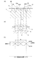
自動車の各車輪にかかる荷重を検出する技術として、図36に展開図で示す電子部品複合体を、円環状の保護カバーの内側に配置して円環状のセンサ組立品とし、このセンサ組立品をシール部材を介して車輪用軸受の外方部材および内方部材のうちの固定側部材の周面に固定側部材と同心に取付けたセンサ付車輪用軸受が提案されている(例えば特許文献1)。同図の電子部品複合体は、前記固定側部材の周面に接触して固定される歪み発生部材51、およびこの歪み発生部材51に取付けられてこの歪み発生部材51の歪みを検出するセンサ52からなる4つのセンサユニット50と、前記センサ52の出力信号を処理する信号処理用IC55と、処理された前記出力信号を軸受外部へ取り出す信号ケーブル56とを含む。
As a technique for detecting a load applied to each wheel of an automobile, an electronic component composite shown in a development view in FIG. 36 is arranged inside an annular protective cover to form an annular sensor assembly. A sensor-equipped wheel bearing has been proposed that is mounted concentrically with the fixed side member on the peripheral surface of the fixed side member of the outer and inner members of the wheel bearing via a seal member (for example, Patent Document 1). . The electronic component composite shown in FIG. 1 is a
また、他の技術として、図37(A),(B)に展開図および断面図で示すように、図36に示した電子部品複合体において、前記センサユニット50、前記信号処理用IC55、および前記信号ケーブル56の間を配線する配線回路を有するフレキシブル基板65を追加した構成のセンサ付車輪用軸受も提案されている(例えば特許文献2)。
As another technique, as shown in development and cross-sectional views in FIGS. 37A and 37B, in the electronic component composite shown in FIG. 36, the
特許文献1に開示のセンサ付車輪用軸受では、前記電子部品複合体を構成するのに、半田付けなどにより4つの歪み発生部材51を信号ケーブル56を介して配線している。このため、信号ケーブル56の配線作業が煩雑でコスト高の要因となっている。
In the sensor-equipped wheel bearing disclosed in
一方、特許文献2に開示のセンサ付車輪用軸受でも、前記電子部品複合体を構成するのに、4つの歪み発生部材51とフレキシブル基板65を半田付けなどにより接続する作業が発生してしまう。また、配線部をハンダで固定した場合、車両走行中に振動などによりハンダ部にクラックが発生し、センサ52が正常に検出作動しないことも考えられる。
On the other hand, even with the sensor-equipped wheel bearing disclosed in
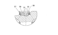
さらに、特許文献2に開示のセンサ付車輪用軸受では、外部環境の泥水などにより、センサ52が腐食するのを防止するために、図38のように円環状の保護カバー57の内側に前記電子部品複合体を配置し、その保護カバー57の外径側溝部にモールド材58を充填している。しかし、この保護カバー57は、図39のように、ヒンジ60を介して半割れ形状とされているため、密封性、組立性、コストの観点から問題があった。また、この保護カバー57は、全体が金属で覆われていないため、車両走行中に跳ねた小石などがぶつかると損傷し、内部のセンサ52が正常に検出動作しなくなる可能性もある。
Furthermore, in the sensor-equipped wheel bearing disclosed in
この発明の目的は、煩雑な配線作業が要らず、配線部の品質向上およびコスト低減が可能で、また走行中に跳ねた小石等の衝突からセンサを保護することができ、かつ外部からの泥水等のセンサへの浸入が防止できて、長期間安定的にセンシングすることが可能なセンサ付車輪用軸受を提供することである。 The object of the present invention is that no complicated wiring work is required, the quality of the wiring part can be improved and the cost can be reduced, the sensor can be protected from the collision of pebbles and the like jumped during traveling, and muddy water from the outside It is possible to provide a sensor-equipped wheel bearing that can prevent intrusion into a sensor and the like and can stably sense for a long period of time.
この発明のセンサ付車輪用軸受は、複列の転走面が内周に形成された外方部材と、前記転走面と対向する転走面が外周に形成された内方部材と、両部材の対向する転走面間に介在した複列の転動体とを備え、車体に対して車輪を回転自在に支持する車輪用軸受において、上記外方部材および内方部材のうちの固定側部材に、この固定側部材に接触して固定される2つ以上の接触固定部を有する歪み発生部材、およびこの歪み発生部材に取付けられてこの歪み発生部材の歪みを検出する2つ以上のセンサからなる荷重検出用センサ部を複数設けてなるセンサ付車輪用軸受であって、前記2つ以上のセンサの出力信号により、車輪用軸受に作用する荷重を推定する推定手段を設け、
前記複数の荷重検出用センサ部の歪み発生部材を、これら複数の荷重検出用センサ部に渡って連続した1つの帯状の歪み発生部材とし、この帯状の歪み発生部材における前記2つ以上の接触固定部を、前記固定側部材の外径面の同一軸方向位置でかつ円周方向に互いに離間した位置となるように配置し、
複数の荷重検出用センサ部を固定側部材の外周を囲む筒状の保護カバーで覆い、この保護カバーの軸方向のいずれか一端で前記固定側部材の外周に嵌合させ、他端の開口縁に弾性体からなる環状のシール部材を設け、このシール部材を前記固定側部材の表面、または上記外方部材および内方部材のうちの回転側部材の表面に接触させたことを特徴とする。
前記固定側部材が外方部材であり、前記回転側部材が前記内方部材であっても良い。前記シール部材は、例えば、リップ部であっても、またOリングであっても良い。
The sensor-equipped wheel bearing according to the present invention includes an outer member having a double-row rolling surface formed on the inner periphery, an inner member having a rolling surface opposed to the rolling surface formed on the outer periphery, A wheel bearing comprising a double row rolling element interposed between opposing rolling surfaces of the member and rotatably supporting the wheel with respect to the vehicle body, wherein the fixed side member of the outer member and the inner member Further, a strain generating member having two or more contact fixing portions fixed in contact with the fixed side member, and two or more sensors attached to the strain generating member and detecting the strain of the strain generating member A sensor-equipped wheel bearing provided with a plurality of load detection sensor units, wherein an estimation means for estimating a load acting on the wheel bearing is provided based on output signals of the two or more sensors.
The strain generating members of the plurality of load detecting sensor portions are used as one belt-like strain generating member continuous over the plurality of load detecting sensor portions, and the two or more contact fixings in the belt-shaped strain generating members are performed. The parts are arranged so as to be at the same axial position on the outer diameter surface of the fixed side member and at positions separated from each other in the circumferential direction,
A plurality of load detection sensors are covered with a cylindrical protective cover that surrounds the outer periphery of the fixed member, and is fitted to the outer periphery of the fixed member at one end in the axial direction of the protective cover. An annular seal member made of an elastic body is provided on the surface, and the seal member is brought into contact with the surface of the stationary member or the surface of the rotating member of the outer member and the inner member.
The stationary member may be an outer member, and the rotating member may be the inner member. The seal member may be, for example, a lip portion or an O-ring.
車輪用軸受や、車輪のタイヤと路面間に荷重が作用すると、車輪用軸受の固定側部材(例えば外方部材)にも荷重が負荷されて変形が生じ、その変形から荷重検出用センサ部が荷重を検出する。荷重検出用センサ部の2つ以上のセンサの出力信号は、転動体の通過の影響を受けるが、推定手段はこれらのセンサの出力信号から、車輪用軸受や車輪と路面間(タイヤ接地面)に作用する力(垂直方向荷重Fz ,駆動力や制動力となる荷重Fx ,軸方向荷重Fy )を推定するものとしているので、2つ以上のセンサの各出力信号に現れる温度の影響やナックル・フランジ面間などの滑りによる影響を相殺ないし緩和することができる。これにより、温度の影響やナックル・フランジ面間などの滑りによる影響を受けることなく、車輪用軸受や、車輪のタイヤと路面間に作用する荷重(垂直方向荷重Fz ,駆動力や制動力となる荷重Fx ,軸方向荷重Fy )を精度良く検出できる。 When a load acts between the wheel bearing or the wheel tire and the road surface, the load is also applied to the stationary side member (for example, the outer member) of the wheel bearing to cause deformation. Detect load. The output signals of two or more sensors in the load detection sensor section are affected by the passage of rolling elements, but the estimation means determines the bearings for wheels and the distance between the wheels and the road surface (tire contact surface) from the output signals of these sensors. Force (vertical load Fz, driving force or braking force Fx, axial load Fy) is estimated, so the temperature effect on each output signal of two or more sensors and knuckle The effect of slippage between the flange surfaces can be offset or reduced. As a result, the load (vertical load Fz, driving force and braking force) acting between the wheel bearing and the tire of the wheel and the road surface without being affected by the temperature or the slippage between the knuckle and the flange surface. The load Fx and the axial load Fy) can be detected with high accuracy.
特に、複数の荷重検出用センサ部の歪み発生部材を、これら複数の荷重検出用センサ部に渡って連続した1つの帯状の歪み発生部材としているので、煩雑な配線作業が要らず、配線部の品質向上およびコスト低減が可能となる。
また、複数の荷重検出用センサ部を有するセンサ組立品を保護カバーで覆ったため、例えば、車両走行中に跳ねた小石等の衝突からセンサを保護するなど、複数の荷重検出用センサ部を外部環境から保護することができる。そのため、外部環境による荷重検出用センサ部の故障を防止して、車輪用軸受やタイヤ接地面に作用する荷重を長期にわたり安定的に検出できる。
さらに、この保護カバーにシール部材を設けてシール機能を付加したため、外部からの泥水等がセンサ内部に浸入するのを防止し、より一層、長期間安定的にセンシングすることが可能となる。
In particular, since the strain generating members of the plurality of load detecting sensor portions are one band-like strain generating member continuous across the plurality of load detecting sensor portions, no complicated wiring work is required. Quality improvement and cost reduction are possible.
In addition, since the sensor assembly having a plurality of load detection sensor portions is covered with a protective cover, the plurality of load detection sensor portions are protected from the external environment by, for example, protecting the sensor from a collision of pebbles or the like jumped while the vehicle is running. Can be protected from. For this reason, it is possible to stably detect the load acting on the wheel bearing and the tire ground contact surface for a long period of time by preventing a failure of the load detection sensor unit due to the external environment.
Furthermore, since a sealing member is added to the protective cover to add a sealing function, muddy water from the outside can be prevented from entering the sensor, and sensing can be performed stably for a longer period of time.
この発明において、前記1つの帯状の歪み発生部材を、その長手方向の複数箇所で屈曲させて、前記固定側部材に固定しても良い。
このように、複数の荷重検出用センサ部を有する1つの帯状の歪み発生部材を複数箇所で屈曲させることにより、固定側部材への取付け作業が容易になる。
In the present invention, the one belt-like strain generating member may be bent at a plurality of locations in the longitudinal direction and fixed to the stationary member.
In this way, by bending one belt-like strain generating member having a plurality of load detection sensor portions at a plurality of locations, the attachment work to the fixed member is facilitated.
この発明において、前記固定側部材が車体への取付け用のフランジを外周に有し、前記固定側部材を軸受軸方向の正面側から見た形状が、軸受軸心と直交する線分に対して線対称となる形状、または軸受軸心を中心とする点対称となる形状であっても良い。
車体取付用のフランジの正面形状をこのような形状とした場合、固定側部材の形状が単純化され、固定側部材の形状の複雑さに起因する温度分布や膨張・収縮量のばらつきを低減できる。これにより、固定側部材における温度分布や膨張・収縮量のばらつきによる影響を十分小さくして、荷重による歪み量を荷重検出用センサ部に検出させることができる。
In this invention, the fixed side member has a flange for attachment to the vehicle body on the outer periphery, and the shape of the fixed side member viewed from the front side in the bearing axial direction is relative to a line segment orthogonal to the bearing axis. It may be a line-symmetric shape or a point-symmetric shape with the bearing axis as the center.
When the front shape of the flange for mounting the vehicle body is such a shape, the shape of the fixed side member is simplified, and variations in temperature distribution and expansion / shrinkage due to the complexity of the shape of the fixed side member can be reduced. . Thereby, the influence by the variation in the temperature distribution and the expansion / contraction amount in the fixed member can be sufficiently reduced, and the load detection sensor unit can detect the strain amount due to the load.
この発明において、前記固定側部材の外径面における少なくとも前記複数の荷重検出用センサ部との接触部分に、耐食性または防食性を有する表面処理を施しても良い。表面処理は金属メッキ、または塗装、またはコーティング処理である。
このように、固定側部材の外径面に耐食性または防食性を有する表面処理を施した場合、固定側部材の外径面の錆により荷重検出用センサ部の取付部が盛り上がったり、荷重検出用センサ部にもらい錆が発生するのを防止でき、錆に起因する歪みセンサの誤動作を解消でき、荷重検出を長期にわたり正確に行なうことができる。
In the present invention, a surface treatment having corrosion resistance or corrosion resistance may be applied to at least a contact portion of the outer diameter surface of the stationary member with the plurality of load detection sensor portions. The surface treatment is metal plating, painting, or coating treatment.
As described above, when the outer diameter surface of the fixed side member is subjected to corrosion resistance or anticorrosion surface treatment, the mounting portion of the load detection sensor portion rises due to the rust of the outer diameter surface of the fixed side member, or the load detection It is possible to prevent the sensor unit from generating rust, eliminate the malfunction of the strain sensor due to rust, and accurately detect the load over a long period of time.
この発明において、前記保護カバーのアウトボード側端を固定側部材の外周面に嵌合させ、前記保護カバーのインボード側端の開口縁に沿って前記環状の弾性体からなるリップ部を設け、このリップ部を、前記固定側部材に設けられたフランジのアウトボード側を向く側面、または前記固定側部材の外周面に接触させても良い。
この構成の場合も、センサを保護カバーで被覆できて、外部環境の影響によるセンサの故障を防止して、車輪用軸受やタイヤ接地面に作用する荷重を長期にわたり正確に検出できる。例えば、外部からの飛び石や泥水,塩水等から、荷重検出用センサ部を確実に保護することができる。保護カバーは、アウトボード側端を固定側部材の外周面に嵌合させて取付けるので、保護カバーの取付作業が容易に行える。また、信号ケーブルの配線処理や荷重検出用センサ部の組付けも容易でコスト低減が可能となる。
前記固定側部材が前記外方部材である場合は、前記保護カバーは外方部材の外周面に取付けられるが、その場合、保護カバーを取付け易くて、保護カバーによる荷重検出用センサ部の保護が行い易い。
In this invention, the outboard side end of the protective cover is fitted to the outer peripheral surface of the stationary member, and a lip portion made of the annular elastic body is provided along the opening edge of the inboard side end of the protective cover. You may make this lip part contact the side surface which faces the outboard side of the flange provided in the said fixed side member, or the outer peripheral surface of the said fixed side member.
Even in this configuration, the sensor can be covered with a protective cover, and the sensor failure due to the influence of the external environment can be prevented, and the load acting on the wheel bearing and the tire ground contact surface can be accurately detected over a long period of time. For example, it is possible to reliably protect the load detection sensor unit from stepping stones, muddy water, salt water, and the like from the outside. Since the protective cover is attached by fitting the outboard side end to the outer peripheral surface of the fixed side member, the protective cover can be easily attached. In addition, the signal cable wiring process and the load detection sensor unit can be easily assembled and the cost can be reduced.
When the stationary member is the outer member, the protective cover is attached to the outer peripheral surface of the outer member. In this case, the protective cover is easy to attach, and the load detection sensor unit is protected by the protective cover. Easy to do.
この構成の場合に、前記保護カバーのインボード側端部に、前記信号ケーブルの保護カバーからの引き出し部が引き出される孔部を設け、信号ケーブル引き出し部が前記孔部から引き出される部分にシール材を塗布しても良い。これにより、信号ケーブルの引出し部における防水,防塵が確実に行える。 In the case of this configuration, a hole portion from which the lead portion of the signal cable is pulled out from the protective cover is provided at an inboard side end portion of the protective cover, and a seal material is provided at a portion where the signal cable lead portion is pulled out from the hole portion. May be applied. As a result, waterproofing and dustproofing can be reliably performed at the signal cable lead-out portion.
また、前記保護カバーのアウトボード側端を前記固定側部材よりもアウトボード側に突出させ、そのアウトボード側端と前記回転側部材との間に非接触シール隙間を形成しても良い。
この構成の場合、保護カバーと回転側部材との間に非接触シール隙間で密封するため、トルク増加を伴うことなく、密封性を向上させることができる。
Further, the outboard side end of the protective cover may be protruded to the outboard side from the fixed side member, and a non-contact seal gap may be formed between the outboard side end and the rotating side member.
In the case of this configuration, since the non-contact sealing gap is sealed between the protective cover and the rotation side member, the sealing performance can be improved without increasing torque.
この場合に、前記保護カバーのアウトボード側端を前記回転側部材に沿う形状としても良い。この構成の場合、保護カバーのアウトボード側端と回転側部材との間に形成される非接触シール隙間がより密封性の高いものとなる。 In this case, the outboard side end of the protective cover may be shaped along the rotation side member. In the case of this configuration, the non-contact seal gap formed between the outboard side end of the protective cover and the rotation side member has a higher sealing performance.
この発明において、前記保護カバーのインボード側端を前記固定側部材に設けられた車体への取付用のフランジの外径面に嵌合させ、前記保護カバーのアウトボード側端の開口縁に沿って前記環状の弾性体からなるリップ部を設け、このリップ部を前記固定側部材の外周面、または前記外方部材および内方部材のうちの回転側部材の表面に接触させても良い。
このように、保護カバーのインボード側端を固定側部材に設けられた車体への取付用のフランジの外径面に嵌合させて取付けるようにした場合、保護カバーの取付作業が容易に行える。しかも、リップが保護カバーに設けられているため、リップ部等のシール手段を保護カバーと別個に取付ける必要がなく、シール手段の取付作業も軽減できる。
前記固定側部材が外方部材である場合は、前記保護カバーは外方部材の外周に取付けられるが、その場合、保護カバーをより一層取付け易くて、保護カバーによるセンサの保護が行い易い。
In this invention, the inboard side end of the protective cover is fitted to the outer diameter surface of the flange for mounting on the vehicle body provided on the fixed side member, and along the opening edge of the outboard side end of the protective cover. A lip portion made of the annular elastic body may be provided, and this lip portion may be brought into contact with the outer peripheral surface of the stationary member or the surface of the rotating member of the outer member and the inner member.
In this way, when the inboard side end of the protective cover is fitted to the outer diameter surface of the flange for mounting on the vehicle body provided on the stationary member, the protective cover can be easily attached. . Moreover, since the lip is provided on the protective cover, it is not necessary to attach the sealing means such as the lip portion separately from the protective cover, and the attaching work of the sealing means can be reduced.
When the stationary member is an outer member, the protective cover is attached to the outer periphery of the outer member. In this case, the protective cover can be more easily attached and the sensor can be easily protected by the protective cover.
この構成の場合に、前記リップ部は、先端がアウトボード側に向かって次第に縮径して延びる形状であり、このリップ部を前記固定側部材の外周面に接触させても良い。この構成の場合、アウトボード側端から保護カバー内への泥水・塩溝等の浸入をより一層確実に防止できる。 In the case of this configuration, the lip portion may have a shape in which the distal end gradually extends toward the outboard side and extends, and the lip portion may be brought into contact with the outer peripheral surface of the fixed side member. In the case of this configuration, the intrusion of muddy water, salt grooves, and the like from the outboard side end into the protective cover can be more reliably prevented.
また、リップ部の一部を前記保護カバーの外周面の一部にまで延長してカバー外周面被覆部分としても良い。前記カバー外周面被覆部分は、リップ部を、保護カバーの外周面へ取付ける場合は、その取付けに必要な強度を得るために保護カバーの外周面に位置させる範囲よりもさらにインボード側へ延びて設ける。この構成の場合、保護カバーの外周面におけるアウトボード側端において、前記カバー外周面被覆部分からなる壁が外径側に張り出すことになり、この壁によりリップ部が外方部材の外周面に当接している部分へ泥水・塩水等が流れ込むのを阻止できる。そのため、保護カバー内への泥水・塩水等の浸入をより確実に防止することができる。 Moreover, it is good also as a cover outer peripheral surface coating | coated part by extending a part of lip part to a part of outer peripheral surface of the said protective cover. When the lip portion is attached to the outer peripheral surface of the protective cover, the cover outer peripheral surface covering portion extends further to the inboard side than the range positioned on the outer peripheral surface of the protective cover in order to obtain the strength required for the attachment. Provide. In the case of this configuration, at the end on the outboard side of the outer peripheral surface of the protective cover, a wall made of the cover outer peripheral surface covering portion projects to the outer diameter side, and this wall causes the lip portion to become the outer peripheral surface of the outer member. Muddy water, salt water, etc. can be prevented from flowing into the abutting part. Therefore, intrusion of muddy water, salt water, etc. into the protective cover can be prevented more reliably.
この発明において、前記リップ部のカバー外周面被覆部分の外周面を、アウトボード側に向かって拡径する傾斜面としても良い。この構成の場合、リップ部が外方部材の外周面に当接している部分へ泥水・塩水等が流れ込むのを阻止でき、保護カバー内への泥水・塩水等の浸入をより確実に防止できる。 In this invention, it is good also considering the outer peripheral surface of the cover outer peripheral surface coating | coated part of the said lip | rip part as an inclined surface which diameter-expands toward an outboard side. In this configuration, it is possible to prevent the muddy water / salt water or the like from flowing into the portion where the lip portion is in contact with the outer peripheral surface of the outer member, and it is possible to more reliably prevent the muddy water / salt water etc. from entering the protective cover.
この発明において、前記保護カバーのアウトボード側端を前記固定側部材よりもアウトボード側に突出させ、そのアウトボード側端と前記回転側部材との間に非接触シール隙間を形成しても良い。この明細書で言う「非接触シール隙間」とは、固定側部材と回転側部材との相対回転が生じている状態で、水等の浸入が防止される程度に狭い隙間を言う。
この構成の場合、保護カバーと固定側部材との間のシールが、リップ部の固定側部材外周面への当接と、保護カバーのアウトボード側端と回転側部材との間に形成される非接触シールとによる二重の密閉構造でなされるので、アウトボード側でのシールがより確実なものとなり、外部環境の影響によるセンサの故障をさらに確実に防止して、荷重検出を正確に行うことができる。
In this invention, the outboard side end of the protective cover may be projected to the outboard side from the fixed side member, and a non-contact seal gap may be formed between the outboard side end and the rotating side member. . The “non-contact seal gap” in this specification refers to a gap that is narrow enough to prevent water or the like from entering in a state where relative rotation between the stationary member and the rotating member occurs.
In the case of this configuration, a seal between the protective cover and the fixed side member is formed between the contact of the lip portion with the outer peripheral surface of the fixed side member and between the outboard side end of the protective cover and the rotating side member. Since it is made of a double sealed structure with a non-contact seal, the seal on the outboard side is more secure, and sensor failure due to the influence of the external environment is more reliably prevented, and load detection is performed accurately. be able to.
この発明において、前記回転側部材は車輪取付用のハブフランジを有し、このハブフランジのインボード側を向く側面に前記リップ部を接触させても良い。
この構成の場合、回転側部材のハブフランジと保護カバーのアウトボード側端との間がリップ部で密封されるので、アウトボード側端から保護カバー内への泥水・塩水等の浸入を確実に防止できる。
In this invention, the said rotation side member has a hub flange for wheel attachment, and you may make the said lip part contact the side surface which faces the inboard side of this hub flange.
In this configuration, since the gap between the hub flange of the rotating side member and the outboard side end of the protective cover is sealed by the lip part, it is ensured that muddy water, salt water, etc. enter the protective cover from the outboard side end. Can be prevented.
この発明において、前記荷重検出用センサ部と、この荷重検出用センサ部の出力信号を処理する信号処理用ICと、処理された前記出力信号を軸受外部へ取り出す信号ケーブルとを含む電子部品をリング状に接続してなるセンサ組立品を、前記固定側部材の外周面に固定側部材と同心に取付けると共に、このセンサ組立品を前記保護カバーで覆っても良い。この構成の場合、センサ組立品と共に、電子部品を保護カバーで被覆できる。 In the present invention, an electronic component including the load detection sensor unit, a signal processing IC for processing an output signal of the load detection sensor unit, and a signal cable for extracting the processed output signal to the outside of the bearing is ringed. A sensor assembly connected in a shape may be attached to the outer peripheral surface of the fixed side member concentrically with the fixed side member, and the sensor assembly may be covered with the protective cover. In this configuration, the electronic component can be covered with the protective cover together with the sensor assembly.
この発明において、前記保護カバーが、耐食性を有する鋼板をプレス加工した成形品であっても良い。前記保護カバーが、耐食性を有する鋼板をプレス加工し、その表面に金属メッキまたは塗装処理を施したものであってもよい。これらの構成の場合、保護カバーが外部環境により腐食するのを防止できる。 In this invention, the protective cover may be a molded product obtained by pressing a corrosion-resistant steel plate. The protective cover may be formed by pressing a corrosion-resistant steel plate and performing metal plating or coating treatment on the surface thereof. In these configurations, the protective cover can be prevented from being corroded by the external environment.
この発明において、前記リップ部を前記保護カバーに一体形成しても良い。リップ部を一体形成すると、リップ部を別部品として製造して保護カバーに組付ける手間が省ける。前記リップ部を構成する弾性体がゴム材料からなるものであっても良い。リップ部を構成する弾性体がゴム材料であると、保護カバーのインボード側端の密封性を確実なものとできる。 In the present invention, the lip portion may be integrally formed with the protective cover. If the lip portion is formed integrally, the labor of manufacturing the lip portion as a separate part and assembling it to the protective cover can be saved. The elastic body constituting the lip portion may be made of a rubber material. When the elastic body constituting the lip portion is a rubber material, the sealing performance of the inboard side end of the protective cover can be ensured.
この発明において、前記推定手段は、前記2つ以上のセンサの出力信号の差分から、出力信号の振幅または振幅に相当する値を演算するものであっても良い。
出力信号の振幅は、転動体の通過や転動体の位置による影響を受けると共に、温度の影響やナックル・フランジ面間などの滑りの影響を受けて、出力信号が変動する。そこで、その出力信号の差分から出力信号の振幅または振幅に相当する値を演算することにより、少なくとも各出力信号に及ぼす温度の影響やナックル・フランジ面間などの滑りの影響を相殺できて、検出精度を上げることができる。
なお、前記「温度の影響」は、軸受の温度変化によって出力信号がシフトすることである。前記「滑りの影響」は、軸受が受ける荷重の変動によって生じる出力信号のシフトである。
(1) シフト要因の時間的変化が緩やかである場合、具体的には転動体の周波数よりも低い場合、見かけ上の振幅の幅は演算で得られる振幅の幅と同等となる。すなわち、振幅の中心位置が変化したと見える。
(2) シフトの要因の時間的変化が転動体の周波数と同じ場合、見かけ上の振幅の幅は(実際の振幅)+(シフト要因による変動)となってしまう。
(3) シフト要因の時間的変化が転動体の周波数よりも高い場合、見かけ上の振幅の周波数は転動体の通過によるものではなく、シフト要因の変化によるものに見えてしまう。
これらのシフト要因は、隣合う2つの出力信号に同相で入力される。したがって、2つのセンサの差分を取ることで、影響を除去することができ、純粋な振幅を検出することが可能となる。
In this invention, the estimation means may calculate the amplitude of the output signal or a value corresponding to the amplitude from the difference between the output signals of the two or more sensors.
The amplitude of the output signal is influenced by the passage of the rolling element and the position of the rolling element, and the output signal fluctuates due to the influence of temperature and the effect of slippage between the knuckle and flange surfaces. Therefore, by calculating the amplitude of the output signal or the value corresponding to the amplitude from the difference between the output signals, at least the effect of temperature on each output signal and the effect of slippage between the knuckle and flange surfaces can be offset and detected. The accuracy can be increased.
The “temperature influence” means that the output signal shifts due to the temperature change of the bearing. The “slip effect” is a shift of an output signal caused by a change in load applied to the bearing.
(1) When the temporal change of the shift factor is moderate, specifically, when it is lower than the rolling element frequency, the apparent amplitude width is equivalent to the amplitude width obtained by the calculation. That is, it appears that the center position of the amplitude has changed.
(2) When the temporal change of the shift factor is the same as the frequency of the rolling element, the apparent amplitude range is (actual amplitude) + (variation due to the shift factor).
(3) When the temporal change of the shift factor is higher than the frequency of the rolling element, the apparent amplitude frequency appears not to be due to the passage of the rolling element but to the change of the shift factor.
These shift factors are input in phase to two adjacent output signals. Therefore, by taking the difference between the two sensors, the influence can be removed and a pure amplitude can be detected.
前記推定手段は、出力信号の差分から信号の絶対値を生成し、そのピーク値または直流成分を、出力信号の振幅相当値としても良い。
前記推定手段は、出力信号の差分から信号の実効値を演算し、その値を出力信号の振幅相当値としても良い。
前記推定手段は、出力信号の差分から、その振動周期の一周期以上の時間区間内における最大値と最小値を求め、その値を出力信号の振幅相当値としても良い。
前記推定手段を、上記のいずれかの処理を行うものとしても、精度良く、かつ簡単な演算で振幅相当値を求めることができる。
The estimation means may generate an absolute value of the signal from the difference between the output signals, and use the peak value or the direct current component as the amplitude equivalent value of the output signal.
The estimation means may calculate an effective value of the signal from the difference between the output signals and set the value as an amplitude equivalent value of the output signal.
The estimation means may obtain a maximum value and a minimum value within a time interval of one or more periods of the vibration period from the difference between the output signals, and use the values as the amplitude equivalent value of the output signal.
Even if the estimation means performs any of the above processes, the amplitude equivalent value can be obtained with high accuracy and simple calculation.
この発明において、前記2つ以上の接触固定部のうち、前記固定側部材の外径面の円周方向配列の両端に位置する2つの接触固定部の間隔を、転動体の配列ピッチと同一としても良い。
この構成の場合、前記2つの接触固定部の中間位置に例えば2つのセンサが配置されていれば、これら両センサの間での前記円周方向の間隔は、転動体の配列ピッチの略1/2となる。その結果、両センサの出力信号は略180度の位相差を有することになり、その差分は温度の影響やナックル・フランジ面間などの滑りの影響を十分相殺した値となる。これにより、推定手段によって推定される車輪用軸受や車輪と路面間に作用する力は、温度の影響やナックル・フランジ面間などの滑りの影響をより確実に排除した正確なものとなる。
In this invention, among the two or more contact fixing parts, the interval between two contact fixing parts located at both ends of the circumferential arrangement of the outer diameter surface of the fixed side member is made the same as the arrangement pitch of the rolling elements. Also good.
In the case of this configuration, if, for example, two sensors are arranged at an intermediate position between the two contact fixing portions, the circumferential interval between the two sensors is approximately 1 / (1) of the arrangement pitch of the rolling elements. 2. As a result, the output signals of both sensors have a phase difference of approximately 180 degrees, and the difference is a value that sufficiently offsets the influence of temperature and the influence of slippage between the knuckle and flange surfaces. Thereby, the force acting between the wheel bearing and the wheel and the road surface estimated by the estimating means becomes accurate with the effect of temperature and the effect of slippage between the knuckle and the flange surface more reliably eliminated.
この発明において、前記2つ以上のセンサにおける隣り合うセンサ間の前記固定側部材の外径面の円周方向についての間隔を、転動体の配列ピッチの{1/2+n(n:整数)}倍またはこれらの値に近似した値としても良い。
2つのセンサの間での前記円周方向の間隔が、転動体の配列ピッチの1/2であると、それらセンサの出力信号は180度の位相差を有することになり、その差分は、温度の影響やナックル・フランジ面間などの滑りの影響を相殺した値となる。これにより、推定手段によって推定される車輪用軸受や車輪と路面間に作用する力は、温度の影響やナックル・フランジ面間などの滑りの影響をより確実に排除した正確なものとなる。
In this invention, the interval in the circumferential direction of the outer diameter surface of the fixed member between adjacent sensors in the two or more sensors is {1/2 + n (n: integer)} times the arrangement pitch of the rolling elements. Or it is good also as a value approximated to these values.
When the circumferential interval between two sensors is ½ of the arrangement pitch of the rolling elements, the output signals of these sensors have a phase difference of 180 degrees, and the difference is the temperature It is a value that offsets the effects of sliding and the effects of slippage between the knuckle and flange surfaces. Thereby, the force acting between the wheel bearing and the wheel and the road surface estimated by the estimating means becomes accurate with the effect of temperature and the effect of slippage between the knuckle and the flange surface more reliably eliminated.
この発明において、前記荷重検出用センサ部は3つの接触固定部と2つのセンサを有し、隣り合う第1および第2の接触固定部の間、および隣り合う第2および第3の接触固定部の間に各センサをそれぞれ取付けても良い。
この構成の場合、両端に位置する2つの接触固定部(第1の接触固定部と第3の接触固定部)の間での前記円周方向の間隔を、転動体の配列ピッチと同一とすると、隣り合う2つのセンサ間での前記円周方向の間隔は転動体の配列ピッチの1/2となる。これにより、推定手段によって推定される車輪用軸受や車輪と路面間に作用する力は、温度の影響やナックル・フランジ面間などの滑りの影響を排除した正確なものとなる。
In the present invention, the load detection sensor unit includes three contact fixing units and two sensors, and is adjacent between the first and second contact fixing units adjacent to each other and between the second and third contact fixing units adjacent to each other. Each sensor may be attached between the two.
In the case of this configuration, when the circumferential interval between the two contact fixing portions (the first contact fixing portion and the third contact fixing portion) located at both ends is the same as the arrangement pitch of the rolling elements. The interval in the circumferential direction between two adjacent sensors is ½ of the arrangement pitch of the rolling elements. As a result, the force acting between the wheel bearing and the wheel and the road surface estimated by the estimating means is accurate without the influence of temperature and the effect of slippage between the knuckle and the flange surface.
この構成の場合に、隣り合う接触固定部または隣り合うセンサの前記固定側部材の外径面の円周方向についての間隔を、転動体の配列ピッチの{1/2+n(n:整数)}倍またはこれらの値に近似した値としても良い。この構成の場合も、各センサの出力信号の差分により、温度の影響やナックル・フランジ面間などの滑りの影響を排除できる。 In the case of this configuration, the interval in the circumferential direction of the outer diameter surface of the fixed member of the adjacent contact fixing portion or the adjacent sensor is {1/2 + n (n: integer)} times the arrangement pitch of the rolling elements. Or it is good also as a value approximated to these values. Also in this configuration, the influence of temperature and the influence of slippage between the knuckle and the flange surface can be eliminated by the difference between the output signals of the sensors.
この発明において、前記歪み発生部材は、平面概形が均一幅の帯状、または平面概形が帯状で側辺部に切欠き部を有する薄板材からなるものとしても良い。
このように、平面概形が均一幅の帯状である薄板材で歪み発生部材を構成した場合、歪み発生部材をコンパクトで低コストなものとできる。
In the present invention, the strain generating member may be formed of a strip having a uniform planar width, or a thin plate material having a planar planar shape and having a notch in the side portion.
As described above, when the strain generating member is formed of a thin plate material having a planar shape with a uniform width, the strain generating member can be made compact and low cost.
この発明において、前記荷重検出用センサ部を、タイヤ接地面に対して上下位置および左右位置となる前記固定側部材の外径面の上面部、下面部、右面部、および左面部に配置しても良い。この構成の場合、複数方向の荷重を推定することができる。すなわち、固定側部材の外径面における上面部と下面部に配置される2つの荷重検出用センサ部の出力信号から垂直方向荷重Fz と軸方向荷重Fy を推定でき、固定側部材の外径面における右面部と左面部に配置される2つの荷重検出用センサ部の出力信号から駆動力や制動力による荷重Fx を推定することができる。 In the present invention, the load detection sensor portions are arranged on the upper surface portion, the lower surface portion, the right surface portion, and the left surface portion of the outer diameter surface of the fixed side member that are in a vertical position and a horizontal position with respect to the tire ground contact surface. Also good. In the case of this configuration, loads in a plurality of directions can be estimated. That is, the vertical direction load Fz and the axial direction load Fy can be estimated from the output signals of the two load detection sensor portions arranged on the upper surface portion and the lower surface portion on the outer diameter surface of the fixed side member. The load Fx caused by the driving force or the braking force can be estimated from the output signals of the two load detecting sensor portions arranged on the right surface portion and the left surface portion.
この発明において、前記推定手段は、さらに前記2つ以上のセンサの出力信号の和も用いて、車輪用軸受に作用する荷重を推定するものとしても良い。
2つ以上のセンサの出力信号の和を取ると、各出力信号に現れる転動体の位置の影響を相殺することができるので、静止時においても荷重を推定できる。差分から温度の影響やナックル・フランジ面間などの滑りの影響を排除できることと相まって、荷重をさらに精度良く検出でき、ローパスフィルタが不要となるため、応答速度も向上する。
In this invention, the estimation means may further estimate the load acting on the wheel bearing using the sum of the output signals of the two or more sensors.
If the sum of the output signals of two or more sensors is taken, the influence of the position of the rolling element appearing in each output signal can be canceled out, so that the load can be estimated even when stationary. Coupled with the fact that the effect of temperature and the effect of slippage between the knuckle and flange surfaces can be eliminated from the difference, the load can be detected with higher accuracy and a low-pass filter is not required, thereby improving the response speed.
この発明において、前記荷重検出用センサ部における前記歪み発生部材の接触固定部が3つであり、前記帯状の歪み発生部材における前記3つの接触固定部を、前記固定側部材の外径面の同一軸方向位置でかつ円周方向に互いに離間した位置となるように配置し、隣り合う前記接触固定部の間隔または隣り合う前記センサの前記固定側部材の外径面の円周方向についての間隔を、転動体の配列ピッチの{1/2+n(n:整数)}倍またはこれらの値に近似した値とし、前記推定手段は、前記前記2つのセンサの出力信号の差分により、車輪用軸受に作用する荷重を推定するものとしても良い。
纏め直して言うと、このセンサ付車輪用軸受は、複列の転走面が内周に形成された外方部材と、前記転走面と対向する転走面が外周に形成された内方部材と、両部材の対向する転走面間に介在した複列の転動体とを備え、車体に対して車輪を回転自在に支持する車輪用軸受において、上記外方部材および内方部材のうちの固定側部材に、この固定側部材に接触して固定される3つの接触固定部を有する歪み発生部材、およびこの歪み発生部材に取付けられてこの歪み発生部材の歪みを検出する2つのセンサからなる荷重検出用センサ部を複数設けてなるセンサ付車輪用軸受であって、前記複数の荷重検出用センサ部の歪み発生部材を、これら複数の荷重検出用センサ部に渡って連続した1つの帯状の歪み発生部材とし、この帯状の歪み発生部材における前記3つの接触固定部を、前記固定側部材の外径面の同一軸方向位置でかつ円周方向に互いに離間した位置となるように配置し、隣り合う前記接触固定部の間隔または隣り合う前記センサの前記固定側部材の外径面の円周方向についての間隔を、転動体の配列ピッチの{1/2+n(n:整数)}倍またはこれらの値に近似した値とし、前記2つのセンサの出力信号の差分により、車輪用軸受に作用する荷重を推定する推定手段を設けたものであってもよい。
In this invention, there are three contact fixing parts of the strain generating member in the load detecting sensor part, and the three contact fixing parts in the belt-like strain generating member are the same on the outer diameter surface of the fixed side member. An axial position and a position spaced apart from each other in the circumferential direction, and an interval between adjacent contact fixing portions or an interval in the circumferential direction of the outer diameter surface of the fixed side member of the adjacent sensor. , {1/2 + n (n: integer)} times the arrangement pitch of the rolling elements or a value approximating these values, and the estimating means acts on the wheel bearing according to the difference between the output signals of the two sensors. It is good also as what estimates the load to do.
To summarize, this sensor-equipped wheel bearing has an outer member in which a double row rolling surface is formed on the inner periphery, and an inner member in which the rolling surface opposite to the rolling surface is formed on the outer periphery. A wheel bearing including a member and a double row rolling element interposed between the rolling surfaces of the two members opposed to each other, wherein the wheel is rotatably supported with respect to the vehicle body, of the outer member and the inner member. A strain generating member having three contact fixing portions fixed to the fixed side member in contact with the fixed side member, and two sensors attached to the strain generating member and detecting the strain of the strain generating member. A sensor-equipped wheel bearing provided with a plurality of load detection sensor sections, wherein the plurality of load detection sensor section strain generating members are continuously formed over the plurality of load detection sensor sections. This band-shaped distortion generating part The three contact fixing portions are arranged at the same axial position on the outer diameter surface of the fixed side member and at positions spaced apart from each other in the circumferential direction, and the adjacent contact fixing portions are spaced or adjacent to each other. The interval in the circumferential direction of the outer diameter surface of the fixed side member of the sensor is set to {1/2 + n (n: integer)} times the arrangement pitch of the rolling elements or a value approximating these two values. An estimation means for estimating a load acting on the wheel bearing may be provided based on the difference between the output signals of the sensors.
この構成によると、2つのセンサの出力信号の差分により、温度の影響やナックル・フランジ面間などの滑りの影響が相殺されるので、これらの影響を受けることなく、車輪用軸受や、車輪のタイヤと路面間に作用する荷重を精度良く検出できる。
特に、複数の荷重検出用センサ部の歪み発生部材を、これら複数の荷重検出用センサ部に渡って連続した1つの帯状の歪み発生部材としているので、煩雑な配線作業が要らず、配線部の品質向上およびコスト低減が可能となる。
According to this configuration, the difference between the output signals of the two sensors cancels out the influence of temperature and the effect of slippage between the knuckle and the flange surface. The load acting between the tire and the road surface can be detected with high accuracy.
In particular, since the strain generating members of the plurality of load detecting sensor portions are one band-like strain generating member continuous across the plurality of load detecting sensor portions, no complicated wiring work is required. Quality improvement and cost reduction are possible.
この発明のセンサ付車輪用軸受の組立方法であって、前記固定側部材の単体の状態、または固定側部材に前記転動体を組み付けた状態で、前記固定側部材の外周面に、複数の荷重検出用センサ部を構成した前記帯状の歪み発生部材を取付け、前記保護カバーを固定側部材の外周面に圧入した後、軸受を組み立てることを特徴とする。
この組立方法によると、固定側部材に取付けた荷重検出用センサ部を保護カバーで覆ったセンサ付車輪用軸受を、容易に組み立てることができる。
In the method for assembling a sensor-equipped wheel bearing according to the present invention, a plurality of loads are applied to the outer peripheral surface of the fixed-side member in a single state of the fixed-side member or in a state where the rolling element is assembled to the fixed-side member. The belt-shaped strain generating member constituting the detection sensor portion is attached, the protective cover is press-fitted into the outer peripheral surface of the stationary member, and then the bearing is assembled.
According to this assembling method, the sensor-equipped wheel bearing in which the load detection sensor portion attached to the fixed member is covered with the protective cover can be easily assembled.
この発明のインホイール型モータ内蔵車輪用軸受装置は、この発明の上記いずれかの構成のセンサ付車輪用軸受を備えたものである。
この構成によると、インホイール型モータ内蔵車輪用軸受装置の、この発明のセンサ付車輪用軸受を適用した場合、この発明の各効果がより効果的に発揮される。
An in-wheel motor-equipped wheel bearing device according to the present invention includes the sensor-equipped wheel bearing according to any one of the above-described configurations of the present invention.
According to this configuration, when the wheel bearing with sensor of the present invention is applied to the in-wheel motor built-in wheel bearing apparatus, each effect of the present invention is more effectively exhibited.
この発明のセンサ付車輪用軸受は、複列の転走面が内周に形成された外方部材と、前記転走面と対向する転走面が外周に形成された内方部材と、両部材の対向する転走面間に介在した複列の転動体とを備え、車体に対して車輪を回転自在に支持する車輪用軸受において、上記外方部材および内方部材のうちの固定側部材に、この固定側部材に接触して固定される2つ以上の接触固定部を有する歪み発生部材、およびこの歪み発生部材に取付けられてこの歪み発生部材の歪みを検出する2つ以上のセンサからなる荷重検出用センサ部を複数設けてなるセンサ付車輪用軸受であって、前記2つ以上のセンサの出力信号の差分により、車輪用軸受に作用する荷重を推定する推定手段を設け、前記複数の荷重検出用センサ部の歪み発生部材を、これら複数の荷重検出用センサ部に渡って連続した1つの帯状の歪み発生部材とし、この帯状の歪み発生部材における前記2つ以上の接触固定部を、前記固定側部材の外径面の同一軸方向位置でかつ円周方向に互いに離間した位置となるように配置し、複数の荷重検出用センサ部を固定側部材の外周を囲む筒状の保護カバーで覆い、この保護カバーの軸方向のいずれか一端で前記固定側部材の外周に嵌合させ、他端の開口縁に弾性体からなる環状のシール部材を設け、このシール部材を前記固定側部材の表面、または上記外方部材および内方部材のうちの回転側部材の表面に接触させたため、煩雑な配線作業が要らず、配線部の品質向上およびコスト低減が可能で、また走行中に跳ねた小石等の衝突からセンサを保護することができ、かつ外部からの泥水等のセンサへの浸入が防止できて、長期間安定的にセンシングすることが可能となる。 The sensor-equipped wheel bearing according to the present invention includes an outer member having a double-row rolling surface formed on the inner periphery, an inner member having a rolling surface opposed to the rolling surface formed on the outer periphery, A wheel bearing comprising a double row rolling element interposed between opposing rolling surfaces of the member and rotatably supporting the wheel with respect to the vehicle body, wherein the fixed side member of the outer member and the inner member Further, a strain generating member having two or more contact fixing portions fixed in contact with the fixed side member, and two or more sensors attached to the strain generating member and detecting the strain of the strain generating member A sensor-equipped wheel bearing provided with a plurality of load detection sensor units, wherein an estimation means for estimating a load acting on the wheel bearing is provided based on a difference between output signals of the two or more sensors. These strain generating members of the load detection sensor One band-like strain generating member continuous over a number of load detecting sensor portions, and the two or more contact fixing portions in the band-like strain generating member are arranged in the same axial direction of the outer diameter surface of the fixed side member It is arranged so that it is at a position and spaced apart from each other in the circumferential direction, and a plurality of load detection sensor parts are covered with a cylindrical protective cover surrounding the outer periphery of the fixed side member, and one of the axial directions of this protective cover One end is fitted to the outer periphery of the fixed side member, and an annular seal member made of an elastic body is provided at the opening edge of the other end. The seal member is provided on the surface of the fixed side member, or the outer member and the inner member. Because it is in contact with the surface of the rotating side member, it is possible to improve the quality and reduce the cost of the wiring part, and to protect the sensor from collisions such as pebbles jumping during traveling. Yes, from outside Can be prevented from entering the sensor such as muddy water is, long-term becomes possible to stably sensing.
この発明のインホイール型モータ内蔵車輪用軸受装置は、この発明の上記いずれかの構成のセンサ付車輪用軸受を備えたものであるため、この発明のセンサ付車輪用軸受の各効果が効果的に発揮されて、センサについての煩雑な配線作業が要らず、配線部の品質向上およびコスト低減が可能で、また走行中に跳ねた小石等の衝突からセンサを保護することができ、かつ外部からの泥水等のセンサへの浸入が防止できて、長期間安定的にセンシングすることが可能となる。 Since the in-wheel type motor-equipped wheel bearing device of the present invention includes the sensor-equipped wheel bearing having any one of the above-described configurations of the present invention, each effect of the sensor-equipped wheel bearing of the present invention is effective. As a result, no complicated wiring work is required for the sensor, the quality of the wiring part can be improved and the cost can be reduced, and the sensor can be protected from collisions such as pebbles that bounce while driving, and from the outside. Intrusion of muddy water into the sensor can be prevented, and stable sensing can be performed for a long period of time.
この発明の第1の実施形態を図1ないし図13と共に説明する。この実施形態は、第3世代型の内輪回転タイプで、駆動輪支持用の車輪用軸受に適用したものである。なお、この明細書において、車両に取付けた状態で車両の車幅方向の外側寄りとなる側をアウトボ−ド側と呼び、車両の中央寄りとなる側をインボード側と呼ぶ。 A first embodiment of the present invention will be described with reference to FIGS. This embodiment is a third generation inner ring rotating type and is applied to a wheel bearing for driving wheel support. In this specification, the side closer to the outer side in the vehicle width direction of the vehicle when attached to the vehicle is referred to as the outboard side, and the side closer to the center of the vehicle is referred to as the inboard side.
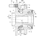
このセンサ付車輪用軸受における軸受は、図1に断面図で示すように、内周に複列の転走面3を形成した外方部材1と、これら各転走面3に対向する転走面4を外周に形成した内方部材2と、これら外方部材1および内方部材2の転走面3,4間に介在した複列の転動体5とで構成される。この車輪用軸受は、複列のアンギュラ玉軸受型とされていて、転動体5はボールからなり、各列毎に保持器6で保持されている。上記転走面3,4は断面円弧状であり、ボール接触角が背面合わせとなるように形成されている。外方部材1と内方部材2との間の軸受空間の両端は、一対のシール7,8によってそれぞれ密封されている。
As shown in the sectional view of FIG. 1, the bearing for this sensor-equipped wheel bearing includes an
外方部材1は固定側部材となるものであって、車体の懸架装置におけるナックル(図示せず)に取付ける車体取付用フランジ1aを外周に有し、全体が一体の部品とされている。フランジ1aには周方向複数箇所にナックル取付用のボルト孔14が設けられ、インボード側よりナックルのボルト挿通孔(図示せず)に挿通したナックルボルト(図示せず)を前記ボルト孔14に螺合することにより、車体取付用フランジ1aがナックルに取付けられる。
内方部材2は回転側部材となるものであって、車輪取付用のハブフランジ9aを有するハブ輪9と、このハブ輪9の軸部9bのインボード側端の外周に嵌合した内輪10とでなる。これらハブ輪9および内輪10に、前記各列の転走面4が形成されている。ハブ輪9のインボード側端の外周には段差を持って小径となる内輪嵌合面12が設けられ、この内輪嵌合面12に内輪10が嵌合している。ハブ輪9の中心には貫通孔11が設けられている。ハブフランジ9aには、周方向複数箇所にハブボルト15の圧入孔16が設けられている。ハブ輪9のハブフランジ9aの根元部付近には、車輪および制動部品(図示せず)を案内する円筒状のパイロット部13がアウトボード側に突出している。
The
The
外方部材1の外周に、荷重検出用のセンサ組立品31が設けられ、このセンサ組立品31は、外方部材1の外周を囲む筒状の保護カバー29で覆われている。
A
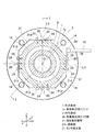
図5は、図1のV−V矢視断面図を示す。なお、図1は、図5におけるI−I矢視断面図を示す。前記車体取付用フランジ1aは、その正面形状が、図5のように軸受軸心Oに直交する線分(例えば図5における縦線分LVあるいは横線分LHに対して線対称となる形状、または軸受軸心Oに対して点対称となる形状とされている。具体的には、この例ではその正面形状が円形とされている。
FIG. 5 shows a cross-sectional view taken along the arrow VV in FIG. FIG. 1 shows a cross-sectional view taken along the line II in FIG. As shown in FIG. 5, the vehicle
固定側部材である外方部材1の外径面には、4つの荷重検出用センサ部20が設けられている。ここでは、これらの荷重検出用センサ部20が、タイヤ接地面に対して上下位置および前後位置となる外方部材1の外径面における上面部、下面部、右面部、および左面部に設けられている。
Four load
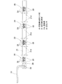
これらの各荷重検出用センサ部20は、図7および図8に拡大平面図および拡大断面図で示すように、歪み発生部材21と、この歪み発生部材21に取付けられて歪み発生部材21の歪みを検出する2つ以上(ここでは2つ)の歪みセンサ22(22A,22B)とでなる。なお、図では歪みセンサにつき符号「22A,22B」を付しているが、2つの歪みセンサの区別の必要がない場合は、「歪みセンサ22」と称する場合がある。これらの荷重検出用センサ部20の歪み発生部材21は、図6に展開平面図で示すように、これら複数の荷重検出用センサ部20にわたって連続した1つの帯状の部材とされる。この歪み発生部材21は、鋼材等の弾性変形可能な金属製で2mm以下の薄板材からなり、平面概形が全長にわたり均一幅の帯状で、各荷重検出用センサ部20の位置ごとに両側辺部に、幅方向に延びるスリット状の切欠き部21bを、2本ずつ平行に有する。ここでは、歪み発生部材21の一側辺部の切欠き部21bは、その側辺部から幅方向に直接切り込んで形成されているが、他側辺部の切欠き部21bは、歪み発生部材21にその長手方向に延びて形成されているスリット21cの途中部分から幅方向に切り込んで形成されている。切欠き部21bの隅部は断面円弧状とされている。また、歪み発生部材21は、各荷重検出用センサ部20の位置ごとに、外方部材1の外径面に接触固定される2つ以上(ここでは3つ)の接触固定部21aを有する。3つの接触固定部21aは、歪み発生部材21の長手方向に向け1列に並べて配置される。
Each of these load
2つの歪みセンサ22は、歪み発生部21における各方向の荷重に対して歪みが大きくなる箇所に貼り付けられる。具体的には、歪み発生部材21の外面側で隣り合う接触固定部21aの間に配置される。つまり、図8において、左端の接触固定部21aと中央の接触固定部21aとの間に1つの歪みセンサ22Aが配置され、中央の接触固定部21aと右端の接触固定部21aとの間に他の1つの歪みセンサ22Bが配置される。切欠き部21bは、図7のように、歪み発生部材21の両側辺部における前記歪みセンサ22A,22Bの配置部に対応する2箇所の位置にそれぞれ形成されている。これにより、歪みセンサ22は歪み発生部材21の切欠き部21bの周辺における長手方向の歪みを検出する。なお、歪み発生部材21は、固定側部材である外方部材1に作用する外力、またはタイヤと路面間に作用する作用力として、想定される最大の力が負荷された状態においても、塑性変形しないものとするのが望ましい。塑性変形が生じると、外方部材1の変形が荷重検出用センサ部20に伝わらず、歪みの測定に影響を及ぼすからである。
The two
前記各荷重検出用センサ部20は、その歪み発生部材21の3つの接触固定部21aが、外方部材1の軸方向に同寸法の位置で、かつ各接触固定部21aが互いに円周方向に離れた位置に来るように配置され、これら接触固定部21aが、それぞれ固定具であるボルト24により外方部材1の外径面に固定される。外方部材1の外径面へ荷重検出用センサ20を安定良く固定する上で、外方部材1の外径面における前記各接触固定部21aが接触固定される箇所には平坦部1bが形成される。前記各ボルト24は、それぞれ接触固定部21aに設けられた径方向に貫通するボルト挿通孔25から外方部材1の外周部に設けられた雌ねじのボルト孔27に螺合させる。外方部材1の外径面における前記歪み発生部材21の3つの接触固定部21aが固定される3箇所の各中間部には溝1cが設けられる。このように、外方部材1の外径面に接触固定部21aを固定することにより、薄板状である歪み発生部材21における切欠き部21bを有する各部位が外方部材1の外径面から離れた状態となり、切欠き部21bの周辺の歪み変形が容易となる。接触固定部21aが配置される軸方向位置として、ここでは外方部材1のアウトボード側列の転走面3の周辺となる軸方向位置が選ばれる。ここでいうアウトボード側列の転走面3の周辺とは、インボード側列およびアウトボード側列の転走面3の中間位置からアウトボード側列の転走面3の形成部までの範囲である。
Each load detecting
このほか、図9に断面図で示すように、歪み発生部材21の3つの接触固定部21aをそれぞれスペーサ23を介してボルト24により外方部材1の外径面に固定することで、外方部材1の外径面への溝1cの形成を省略し、歪み発生部材21における切欠き部21bが位置する各部位を外方部材1の外径面から離すようにしても良い。
In addition, as shown in a cross-sectional view in FIG. 9, the three
歪みセンサ22としては、種々のものを使用することができる。例えば、歪みセンサ22を金属箔ストレインゲージで構成することができる。その場合、通常、歪み発生部材21に対しては接着による固定が行なわれる。また、歪みセンサ22を歪み発生部材21上に厚膜抵抗体にて形成することもできる。
4つの荷重検出用センサ部20にわたって連続した1つの帯状部材とされる歪み発生部材21は、図5に示すように、隣り合う荷重検出用センサ部20の各中間位置となる複数箇所(ここでは6箇所)が一方向に屈曲された屈曲部21dとされ、同図のように外方部材1の外周を取り巻くように外方部材1に取付けられる。また、歪み発生部材21には、各荷重検出用センサ部20の歪みセンサ22からの出力信号を処理する信号処理用IC28と、処理された信号を外部に取り出す信号ケーブル33と、信号処理用IC28と信号ケーブル33を接続するコネクタ34が設けられる。4つの荷重検出用センサ部20における各歪みセンサ22は、歪み発生部材21上に設けられた配線用の回路パターン(図示せず)により前記信号処理用IC28に接続される。このように、4つの荷重検出用センサ部20と、これらの荷重検出用センサ部20にわたって連続した歪み発生部材21と、この歪み発生部材21に別に設けられる信号処理用IC28と、信号ケーブル33と、コネクタ34とが複合して、一体となった1つの電子部品複合体であるセンサ組立品31が構成され、このセンサ組立品31を前記外方部材1の外径面に取付けることにより、センサ付車輪用軸受が構成される。
As shown in FIG. 5, the
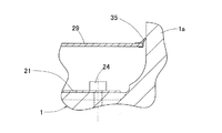
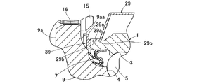
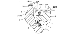
次に、図1ないし図4と共に、前記保護カバー29につき説明する。保護カバー29は、外方部材1の外周を囲む筒状の部材であり、そのアウトボード側端が、他の部分に対して小径となった嵌合筒部29oで外方部材1の外周面に嵌合させられる。保護カバー29のインボード側端には、シール部材として、その開口縁に沿って環状の弾性体からなるリップ部35が設けられ、このリップ部35が外方部材1の車体取付用フランジ1aのアウトボード側を向く側面に当接させられる。これにより、保護カバー29のアウトボード側端およびインボード側端と外方部材1の外周面との間が密封される。リップ部35は、前記フランジ1aの外周面に当接させても良い。
Next, the
前記リップ部35を構成する弾性体としてはゴム材料が望ましい。これにより、リップ部35による保護カバー29のインボード側端の密封性を確実なものとすることができる。このほか、リップ部35を保護カバー29に一体形成しても良い。ここでは、図3に拡大断面図で示すように、リップ部35を、インボード側に向かって拡径する形状としている。これにより、インボード側端から保護カバー29内への泥水・塩水等の浸入をより確実に防止できる。
As the elastic body constituting the
保護カバー29は、例えば耐食性を有する鋼板をプレス加工して成形される。これにより、保護カバー29が外部環境により腐食するのを防止できる。このほか、鋼板をプレス加工して保護カバー29を成形し、その表面に金属メッキまたは塗装処理を施しても良い。この場合も、保護カバー29が外部環境により腐食するのを防止できる。保護カバー29の材質は、このほかプラスチックやゴムであっても良い。
The
図2のIV−IV矢視断面図を示す図4のように、保護カバー29のインボード側端部には、前記センサ組立品31における信号ケーブル33の引き出し部33Bを外側に引き出す孔部36が設けられ、この孔部36から信号ケーブル引き出し部33Bが引き出される部分にシール材37が塗布される。シール材37により孔部36は封止される。これにより、保護カバー29から信号ケーブル引き出し部33Bが引き出される部分の密封性を確実なものとすることができる。
As shown in FIG. 4 showing a cross-sectional view taken along the line IV-IV in FIG. And a sealing
このセンサ付車輪用軸受の組立は、以下の手順で行われる。先ず、外方部材1の単体の状態、または外方部材1に転動体5を組み付けた状態で、外方部材1の外周面に荷重検出用センサ部20を含む電子部品からなるセンサ組立品31を取付ける。つぎに、筒状の保護カバー29を、外方部材1のアウトボード側からその外周面に圧入してそのアウトボード側端を外方部材1の外周面に嵌合させると共に、保護カバー29のインボード側端のリップ部35を外方部材1の車体取付用フランジ1aのアウトボード側を向く側面または外周面に当接させることで、荷重検出用センサ部20を含む電子部品からなるセンサ組立品31を保護カバー29で覆う。この後で軸受の全体を組み立てる。この手順で組み立てることにより、外方部材1に取付けた荷重検出用センサ部20、もしくは荷重検出用センサ部20を含むセンサ組立品31を保護カバー29で覆ってなるセンサ付車輪用軸受を、容易に組み立てることができる。
The assembly of the sensor-equipped wheel bearing is performed according to the following procedure. First, in a state where the
前記荷重検出用センサ部20の作用および具体的構成を説明すする。各荷重検出用センサ部20の2つの歪みセンサ22(22A,22B)の出力信号は、前記信号処理用IC28、信号ケーブル33を経て車両側の推定手段32(図1)に入力される。推定手段32は、荷重検出用センサ部20の2つの歪みセンサ22A,22Bの出力信号から、車輪用軸受や車輪と路面間(タイヤ接地面)に作用する力(垂直方向荷重Fz ,駆動力や制動力となる荷重Fx ,軸方向荷重Fy )を推定する手段である。前記推定手段32は、この実施形態では、前記2つの歪みセンサ22A,22Bの出力信号の差分(具体的には出力信号の振幅)から前記各作用力Fx ,Fy,Fzを推定する。この推定手段32は、前記垂直方向荷重Fz ,駆動力や制動力となる荷重Fx ,軸方向荷重Fy と、2つの歪みセンサ22A,22Bの出力信号の差分との関係を演算式またはテーブル等により設定した関係設定手段(図示せず)を有し、2つの歪みセンサ22A,22Bの出力信号の差分から前記関係設定手段を用いて作用力(垂直方向荷重Fz ,駆動力や制動力となる荷重Fx ,軸方向荷重Fy )を推定する。前記関係設定手段の設定内容は、予め試験やシミュレーションで求めておいて設定する。
なお、前記推定手段32は、前記出力信号の差分に限らず、例えば、前記2つの歪みセンサ22A,22Bの出力信号の和や、平均値、振幅値、振幅中心値などの情報から、これらを適宜用いて、例えば線形結合的に用いて、各作用力Fx Fy,Fzを推定するようにしても良い。その場合も、前記和や平均値などの情報と前記各作用力Fx Fy,Fzとの関係を、演算式またはテーブル等により設定した関係設定手段を用いても良い。
The operation and specific configuration of the load
The estimation means 32 is not limited to the difference between the output signals, and for example, based on information such as the sum of the output signals of the two
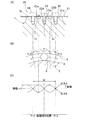
荷重検出用センサ部20は、外方部材1のアウトボード側列の転走面3の周辺となる軸方向位置に設けられるので、歪みセンサ22A,22Bの出力信号は、図10のように荷重検出用センサ部20の設置部の近傍を通過する転動体5の影響を受ける。また、軸受の停止時においても、歪みセンサ22A,22Bの出力信号A,Bは、転動体5の位置の影響を受ける。すなわち、転動体5が荷重検出用センサ部20における歪みセンサ22A,22Bに最も近い位置を通過するとき(または、その位置に転動体5があるとき)、歪みセンサ22A,22Bの出力信号A,Bは最大値となり、図10(B),(C)のように転動体5がその位置から遠ざかるにつれて(または、その位置から離れた位置に転動体5があるとき)低下する。軸受回転時には、転動体5は所定の配列ピッチPで前記荷重検出用センサ部20の設置部の近傍を順次通過するので、歪みセンサ22A,22Bの出力信号A,Bは、転動体5の配列ピッチPを周期として図10(C)に実線で示すように周期的に変化する正弦波に近い波形となる。また、歪みセンサ22A,22Bの出力信号A,Bは、温度の影響やナックルと車体取付用フランジ1a(図1)の面間などの滑りによるヒステリシスの影響を受ける。
Since the load
この実施形態では、前記2つの歪みセンサ22A,22Bの出力信号A,Bの差分を演算処理することで、推定手段32が車輪用軸受や車輪と路面間(タイヤ接地面)に作用する力(垂直方向荷重Fz ,駆動力や制動力となる荷重Fx ,軸方向荷重Fy )を推定するものとしているので、2つの歪みセンサ22A,22Bの各出力信号A,Bに現れる温度の影響やナックル・フランジ面間などの滑りの影響を相殺することができ、これにより車輪用軸受やタイヤ接地面に作用する荷重を正確に検出することができる。
In this embodiment, by calculating the difference between the output signals A and B of the two
差分の演算処理について説明する。
前記2つの歪みセンサ22A,22Bの出力信号A,Bの差分から、演算処理によって差分信号の振幅、または振幅に相当する値を求める方法としては、絶対値|A−B|からそのピーク値を検出するものでも良い。絶対値|A−B|は、演算回路によって生成しても良いが、デジタル演算処理によって計算しても良い。回転状態では半波整流波形が得られるため、そのピーク値をホールドするか、ローパスフィルタ;Low Pass Filter ,略称LPF によって直流成分を求めて差分信号の振幅相当値とすることができる。また、差分信号(A−B)の実効値(二乗平均値)を振幅相当値として荷重の推定演算に用いても良い。デジタル演算処理においては、差分信号の振動周期の一周期以上を演算対象区間に設定し、その区間内の最大値と最小値を検出することで、振幅相当値を算出するものでも良い。
The difference calculation process will be described.
As a method of obtaining the amplitude of the difference signal or a value corresponding to the amplitude from the difference between the output signals A and B of the two
荷重検出用センサ部20として、図8の構成例のものを示す図10においては、固定側部材である外方部材1の外径面の円周方向に並ぶ3つの接触固定部21aのうち、その配列の両端に位置する2つの接触固定部21aの間隔を、転動体5の配列ピッチPと同一に設定している。この場合、隣り合う接触固定部21aの中間位置にそれぞれ配置される2つの歪みセンサ22A,22Bの間での前記円周方向の間隔は、転動体5の配列ピッチPの略1/2となる。その結果、2つの歪みセンサ22A,22Bの出力信号A,Bは略180度の位相差を有することになり、その差分は温度の影響やナックル・フランジ面間などの滑りの影響を十分相殺した値となる。これにより、2つの歪みセンサ22A,22Bの出力信号A,Bの差分から、推定手段32によって推定される車輪用軸受や車輪と路面間(タイヤ接地面)に作用する力(垂直方向荷重Fz ,駆動力や制動力となる荷重Fx ,軸方向荷重Fy )は、温度の影響やナックル・フランジ面間などの滑りの影響をより確実に排除した正確なものとなる。
In FIG. 10 showing the configuration example of FIG. 8 as the load
図11には、図8の構成例の荷重検出用センサ部20において、2つの歪みセンサ22A,22Bの間での前記円周方向の間隔を、転動体5の配列ピッチPの1/2に設定した例を示している。この例では、2つの歪みセンサ22A,22Bの間での前記円周方向の間隔が、転動体5の配列ピッチPの1/2とされるので、2つの歪みセンサ22A,22Bの出力信号A,Bは180度の位相差を有することになり、その差分は、温度の影響やナックル・フランジ面間などの滑りの影響を完全に相殺した値となる。これにより、推定手段32によって推定される車輪用軸受や車輪と路面間(タイヤ接地面)に作用する力(垂直方向荷重Fz ,駆動力や制動力となる荷重Fx ,軸方向荷重Fy )から、温度の影響やナックル・フランジ面間などの滑りの影響をより確実に排除することができる。
なお、この場合に、2つの歪みセンサ22A,22Bの前記円周方向の間隔を、転動体5の配列ピッチPの{1/2+n(n:整数)}倍、またはこれらの値に近似した値としても良い。この場合にも、両歪みセンサ22A,22Bの出力信号A,Bの差分は、温度の影響やナックル・フランジ面間などの滑りの影響を相殺した値となる。
In FIG. 11, in the load
In this case, the circumferential distance between the two
図12には、荷重検出用センサ部20として、図8の構成例のものにおいて、中間位置の接触固定部21aを省略して、接触固定部21aを2つとした構成例(図12(A))の場合を示している。この場合、図10の例の場合と同様に、2つの接触固定部21aの間隔を、転動体5の配列ピッチPと同一に設定している。これにより、2つの接触固定部21aの間に配置される2つの歪みセンサ22A,22Bの間での前記円周方向の間隔は、転動体5の配列ピッチPの略1/2となる。その結果、2つの歪みセンサ22A,22Bの出力信号A,Bは略180度の位相差を有することになり、その差分は温度の影響やナックル・フランジ面間などの滑りの影響を十分相殺した値となる。これにより、2つの歪みセンサ22A,22Bの出力信号A,Bの差分から、推定手段32によって推定される車輪用軸受や車輪と路面間(タイヤ接地面)に作用する力(垂直方向荷重Fz ,駆動力や制動力となる荷重Fx ,軸方向荷重Fy )は、温度の影響やナックル・フランジ面間などの滑りの影響をより確実に排除した正確なものとなる。
図13には、図12(A)の構成例の荷重検出用センサ部20において、2つの歪みセンサ22A,22Bの間での前記円周方向の間隔を、転動体5の配列ピッチPの1/2に設定した例を示している。この例でも、図11の例の場合と同様に、2つの歪みセンサ22A,22Bの出力信号A,Bは180度の位相差を有することになり、その差分は、温度の影響やナックル・フランジ面間などの滑りの影響を完全に相殺した値となる。これにより、推定手段32によって推定される車輪用軸受や車輪と路面間(タイヤ接地面)に作用する力(垂直方向荷重Fz ,駆動力や制動力となる荷重Fx ,軸方向荷重Fy )から、温度の影響やナックル・フランジ面間などの滑りの影響をより確実に排除することができる。
FIG. 12 shows a configuration example in which the
In FIG. 13, in the load
この場合、2つの歪みセンサ22A,22Bの前記円周方向の間隔を、転動体5の配列ピッチPの{1/2+n(n:整数)}倍、またはこれらの値に近似した値としても良い。この場合にも、両歪みセンサ22A,22Bの出力信号A,Bの差分は、温度の影響やナックル・フランジ面間などの滑りの影響を相殺した値となる。
In this case, the circumferential interval between the two
このほか、図10および図11において、隣り合う2つの接触固定部21aの間での前記円周方向の間隔を、転動体5の配列ピッチPの{1/2+n(n:整数)}倍、またはこれらの値に近似した値としても良い。この場合にも、隣り合う2つの歪みセンサ22A,22Bの出力信号A,Bの差分は、温度の影響やナックル・フランジ面間などの滑りの影響を相殺した値となる。
In addition, in FIGS. 10 and 11, the circumferential interval between two adjacent
上記構成のセンサ付車輪用軸受によると、車輪用軸受や、車輪のタイヤと路面間に荷重が作用すると、車輪用軸受の固定側部材である外方部材1にも荷重が印加されて変形が生じる。荷重検出用センサ部20における切欠き部21bを有する歪み発生部材21の3つの接触固定部21aが外方部材1に接触固定されているので、外方部材1の歪みが歪み発生部材21に拡大して伝達され、その歪みが歪みセンサ22A,22Bで感度良く検出され、その出力信号から荷重を推定できる。ここでは、外方部材1の外径面における上面部と下面部に配置される2つの荷重検出用センサ部20の出力信号から垂直方向荷重Fz と軸方向荷重Fy を推定でき、外方部材1の外径面における右面部と左面部に配置される2つの荷重検出用センサ部20の出力信号から駆動力や制動力による荷重Fx を推定できる。
According to the wheel bearing with sensor having the above-described configuration, when a load acts between the wheel bearing or the wheel tire and the road surface, the load is also applied to the
この場合、各荷重検出用センサ部20における歪みセンサ22A,22Bの出力信号A,Bは、上記したようにそのままでは温度の影響やナックル・フランジ面間などの滑りの影響を受けるが、推定手段32ではその2つの出力信号の差分から、車輪用軸受や、車輪のタイヤと路面間に作用する荷重(垂直方向荷重Fz ,駆動力や制動力となる荷重Fx ,軸方向荷重Fy )を推定するので、温度の影響やナックル・フランジ面間などの滑りの影響が解消され、荷重を精度良く推定できる。
In this case, the output signals A and B of the
特に、このセンサ付車輪用軸受では、複数の荷重検出用センサ部20の歪み発生部材21を、これら複数の荷重検出用センサ部20にわたって連続した1つの帯状の部材で構成しているので、煩雑な配線作業が要らず、配線部の品質向上およびコスト低減が可能となる。
In particular, in this wheel bearing with sensor, the
また、この実施形態では、前記歪み発生部材21を、その長手方向の複数箇所で屈曲させて、固定側部材である外方部材1に固定するようにしているので、外方部材1への取付け作業も容易になる。
Further, in this embodiment, the
固定側部材である外方部材1の外径面に固定される荷重径用センサ部20の各接触固定部21aの軸方向寸法が異なると、外方部材1の外径面から接触固定部21aを介して歪み発生部材21に伝達される歪みも異なる。この実施形態では、荷重検出用センサ部20の各接触固定部21aを、外方部材1の外径面に対して軸方向に同寸法となるように設けているので、歪み発生部材21に歪みが集中しやすくなり、それだけ検出感度が向上する。
If the axial dimension of each
また、この実施形態では、荷重検出用センサ部20の歪み発生部材21は、平面概形が均一幅の帯状、または平面概形が帯状で側辺部に切欠き部21bを有する薄板材からなるものとしているので、外方部材1の歪みが歪み発生部材21に拡大して伝達され易く、その歪みが歪みセンサ22A,22Bで感度良く検出され、その出力信号A,Bに生じるヒステリシスも小さくなり、荷重を精度良く推定できる。また、歪み発生部材21の形状も簡単なものとなり、コンパクトで低コストなものとできる。
Further, in this embodiment, the
また、歪み発生部材21の切欠き部21bの隅部は断面円弧状とされているので、切欠き部21bの隅部に歪みが集中せず、塑性変形する可能性が低くなる。切欠き部21bの隅部に歪みが集中しなくなることで、歪み発生部材21における検出部つまり歪みセンサ22A,22Bの取付け部での歪み分布のばらつきが小さくなり、歪みセンサ22A,22Bの取付け位置が歪みセンサ22A,22Bの出力信号A,Bに及ぼす影響も小さくなる。これにより、荷重をさらに精度良く推定できる。
In addition, since the corner of the
特に、このセンサ付車輪用軸受によると、複数の荷重検出用センサ部20を、固定側部材である外方部材1の外周を囲む筒状の保護カバー29で覆い、この保護カバー29のアウトボード側端を外方部材1の外周面に嵌合させ、保護カバー29のインボード側端の開口縁に沿って設けた環状の弾性体からなるリップ部35を外方部材1の車体取付用フランジ1aのアウトボード側を向く側面もしくは外周面に当接させている。このため、外部環境により荷重検出用センサ部20が故障する(飛び石による損傷や、泥水・塩水などによる腐食)のを防止でき、長期にわたって荷重を正確に検出することができ、信号ケーブル33の配線処理や荷重検出用センサ部20の組付けも容易でコスト低減が可能となる。
In particular, according to the wheel bearing with sensor, a plurality of load detecting
また、この実施形態では、荷重検出用センサ部20と、この荷重検出用センサ部20の出力信号を処理する信号処理用IC28と、処理された前記出力信号を軸受外部へ取り出す信号ケーブル33とを含む電子部品をリング状に接続してセンサ組立品31とし、このセンサ組立品31を、固定側部材である外方部材1の外周面に外方部材1と同心に取付けている。このセンサ組立品31を前記保護カバー29で覆っている。このため、荷重検出用センサ部20だけでなく、センサ組立品31を構成する信号処理用IC28、信号ケーブル33などの他の電子部品をも、外部環境による故障から保護することができる。
In this embodiment, the load
なお、上記説明では車輪のタイヤと路面間の作用力を検出する場合を示したが、車輪のタイヤと路面間の作用力だけでなく、車輪用軸受に作用する力(例えば予圧量)を検出するものとしてでも良い。
このセンサ付車輪用軸受から得られた検出荷重を自動車の車両制御に使用することにより、自動車の安定走行に寄与できる。また、このセンサ付車輪用軸受を用いると、車両にコンパクトに荷重センサを設置でき、量産性に優れたものとでき、コスト低減を図ることができる。
In the above description, the case where the acting force between the wheel tire and the road surface is detected is shown, but not only the acting force between the wheel tire and the road surface but also the force acting on the wheel bearing (for example, the preload amount) is detected. It can be as well.
By using the detected load obtained from the sensor-equipped wheel bearing for vehicle control of the automobile, it is possible to contribute to stable running of the automobile. In addition, when this sensor-equipped wheel bearing is used, a load sensor can be installed in a compact vehicle, the mass productivity can be improved, and the cost can be reduced.
また、この実施形態では、固定側部材である外方部材1の車体取付用フランジ1aの正面形状を、図5のように軸受軸心Oに直交する線分(例えば図5における縦線分LVあるいは横線分LH)に対して線対称となる形状、または軸受軸心Oに対して点対称となる形状(具体的には円形)としているので、外方部材1のフランジ1aが単純化され、外方部材1の形状の複雑さに起因する温度分布や膨張・収縮量のばらつきを低減できる。これにより、固定側部材である外方部材1における温度分布や膨張・収縮量のばらつきによる影響を十分小さくして、荷重による歪み量を荷重検出用センサ部に検出させることができる。
Further, in this embodiment, the front shape of the vehicle
また、この実施形態では、荷重検出用センサ部20を、外方部材1における複列の転走面3のうちのアウトボード側の転走面3の周辺となる軸方向位置、つまり比較的設置スペースが広く、タイヤ作用力が転動体5を介して外方部材1に伝達されて比較的変形量の大きい部位に配置しているので、検出感度が向上し、荷重をより精度良く推定できる。
Further, in this embodiment, the load
また、この実施形態では、固定側部材である外方部材1の外径面の上面部と下面部、および右面部と左面部に荷重検出用センサ部20を設けているので、どのような荷重条件においても、荷重を精度良く推定することができる。すなわち、ある方向への荷重が大きくなると、転動体5と転走面3が接触している部分と接触していない部分が180度位相差で現れるため、その方向に合わせて荷重検出用センサ部20を180度位相差で設置すれば、どちらかの荷重検出用センサ部20には必ず転動体5を介して外方部材1に負荷される荷重が伝達され、その荷重を歪みセンサ22A,22Bにより検出可能となる。
In this embodiment, since the load
なお、上記実施形態では、推定手段32が、2つ以上の歪みセンサ22A,22Bの出力信号A,Bの差分から、車輪用軸受に作用する荷重を推定するものとしたが、推定手段32は、さらに前記2つ以上の歪みセンサ22A,22Bの出力信号A,Bの和も用いて、車輪用軸受に作用する荷重を推定するものとしても良い。このように、2つ以上の歪みセンサ22A,22Bの出力信号A,Bの和を取ると、各出力信号A,Bに現れる転動体5の位置の影響を相殺することができるので、差分から温度の影響やナックル・フランジ面間などの滑りの影響を排除できることと相まって、荷重をさらに精度良く検出できる。
In the above embodiment, the estimating means 32 estimates the load acting on the wheel bearing from the difference between the output signals A and B of the two or
図14は、この発明の他の実施形態を示す。このセンサ付車輪用軸受では、図1〜図13に示した実施形態において、前記荷重検出用センサ部20が取付けられる外方部材1の外周面における少なくとも荷重検出用センサ部20との接触部分に、耐食性または防食性を有する表面処理層38が形成されている。ここでは、外方部材1の外周面の全域にわたって表面処理層38を形成した場合を示したが、車体取付用フランジ1aよりもアウトボード側の外周面に限定して表面処理層38を形成しても良い。なお、図14では、図1の保護カバー29については、図示を省略している。また、表面処理層38は、以下に示す各実施形態においても、上記と同様に設けても良い。
FIG. 14 shows another embodiment of the present invention. In this sensor-equipped wheel bearing, in the embodiment shown in FIGS. 1 to 13, at least the contact portion with the load
耐食性または防食性を有する表面処理層38としては、例えば金属メッキ処理によるメッキ層や、塗装処理による塗装膜、コーティング処理によるコーティング層等が挙げられる。金属メッキ処理としては、亜鉛メッキ、ユニクロメッキ、クロメートメッキ、ニッケルメッキ、クロムメッキ、無電解ニッケルメッキ、カニゼンメッキ、四三酸化鉄皮膜(黒染め)、レイデントなどの処理が適用可能である。塗装処理としては、カチオン電着塗装、アニオン電着塗装、フッ素系電着塗装等の電着塗装が適用できる。コーティング処理としては、窒化珪素等のセラミックコーティングなどが適用可能である。
Examples of the
このように、固定側部材である外方部材1の外周面の少なくとも荷重検出用センサ部20との接触部分に耐食性または防食性を有する表面処理層38を形成することにより、外方部材1の外周面の錆により荷重検出用センサ部20の取付部が盛り上がったり、荷重検出用センサ部20にもらい錆が発生するのを防止でき、錆に起因する歪みセンサ22A,22Bの誤動作を解消でき、荷重検出をさらに長期にわたり正確に行うことができる。また、荷重検出用センサ部20を含む前記センサ組立品33が取付けられる外方部材1の外周面に前記表面処理層38を形成した場合、センサ組立品33の取付部が錆で盛り上がったりするのを防止でき、錆に起因する歪みセンサ22A,22Bの誤動作をさらに解消できる。
Thus, by forming the
また、外方部材1の外周面の車体取付用フランジ1aよりもアウトボード側だけに限定して表面処理層38を形成した場合には、外方部材1の転走面3を研削加工する際に、外方部材1の外周面のインボード側端の表面未処理部を保持することができ、高精度に転走面3を研削加工することができる。
Further, when the
図15および図16は、この発明のさらに他の実施形態を示す。このセンサ付車輪用軸受では、図1〜図13に示す実施形態において、保護カバー29のアウトボード側端を外方部材1よりもアウトボード側に突出させ、そのアウトボード側端と、回転側部材である内方部材2との間に非接触シール隙間39、すなわちラビリンスシールを形成している。ここでは、図16に拡大断面図で示すように、保護カバー29のアウトボード側端に、外方部材1のアウトボード側端に沿って内径側に折り曲げられる内側折り曲げ部29aを形成し、つぎにその内側折り曲げ部29aの先端から外径側に折り返されて内側折り曲げ部29aと重なる外側折り曲げ部29bを形成し、さらに外側折り曲げ部29bの先端から内方部材2のハブフランジ9aの基部の曲面部分9aaに向けて延びる筒部29cを形成している。これにより、前記外側折り曲げ部29bから筒部29cにわたる部分とハブフランジ9aの基部曲面部分9aaとの間に狭幅の非接触シール隙間39が形成される。その他の構成は図1〜図13の実施形態の場合と同様である。
15 and 16 show still another embodiment of the present invention. In the wheel bearing with sensor, in the embodiment shown in FIGS. 1 to 13, the outboard side end of the
このように、保護カバー29のアウトボード側端と内方部材2との間に非接触シール隙間39を形成することにより、保護カバー29のアウトボード側端でのシール性が向上し、外部環境の影響によるセンサの故障をさらに確実に防止して、荷重検出を正確に行うことができる。
Thus, by forming the
図17および図18は、この発明のさらに他の実施形態を示す。このセンサ付車輪用軸受では、図15および図16に示す実施形態において、保護カバー29のアウトボード側端の外側折り曲げ部29bの先端の筒部29cを、図18に拡大断面図で示すようにハブフランジ9aの側面に沿う断面L字状に形成している。その他の構成は図15,図16に示す実施形態の場合と同様である。
17 and 18 show still another embodiment of the present invention. In this sensor wheel bearing, in the embodiment shown in FIGS. 15 and 16, the
このように、保護カバー29のアウトボード側端の外側折り曲げ部29bの先端の筒部29cをハブフランジ9aの側面に沿う断面L字状に形成することにより、前記外側折り曲げ部29bから筒部29cにわたる部分とハブフランジ9aの基部曲面部分9aaとの間に形成される非接触シール隙間39が、ハブフランジ9aの側面に沿った形状となる。これにより、保護カバー29のアウトボード側において、浸入してくる泥水などがハブフランジ9aの側面に沿った前記非接触シール隙間39から外側に向けて流れ易くなり、保護カバー29のアウトボード側端でのシール性がさらに向上する。
In this manner, the
図19および図20は、この発明のさらに他の実施形態を示す。このセンサ付車輪用軸受では、図15および図16に示す実施形態において、保護カバー29のアウトボード側端の外側折り曲げ部29bを、図20に拡大断面図で示すように内側折り曲げ部29aの外径側基端よりもさらに外径側まで延ばしている。その他の構成は図15および図16に示す実施形態の場合と同様である。
19 and 20 show still another embodiment of the present invention. In this embodiment of the wheel bearing with sensor, in the embodiment shown in FIGS. 15 and 16, the outer bent portion 29b at the end of the outboard side of the
このように、保護カバー29のアウトボード側端の外側折り曲げ部29bを内側折り曲げ部29aの外径側基端よりもさらに外径側まで延ばすことにより、前記外側折り曲げ部29bから筒部29cにわたる部分とハブフランジ9aの基部曲面部分9aaとの間に形成される非接触シール隙間39の径方向距離がより長くなる。これにより、保護カバー29のアウトボード側端でのシール性がさらに向上する。
In this way, by extending the outer bent portion 29b at the outboard side end of the
図21および図22は、この発明のさらに他の実施形態を示す。このセンサ付車輪用軸受では、図22に拡大断面図で示すように、保護カバー29のアウトボード側端を外方部材1よりもアウトボード側に突出させ、そのアウトボード側端から外径側に折り曲げられる外側折り曲げ部29dを形成し、つぎにその外側折り曲げ部29dの先端から内径側に折り返されて外側折り曲げ部29dと重なる内側折り曲げ部29eを形成し、さらに内側折り曲げ部29eの先端から内方部材2のハブフランジ9aの基部の曲面部分9aaに向けて延びる筒部29fを形成している。これにより、前記内側折り曲げ部29eから筒部29fにわたる部分とハブフランジ9aの基部曲面部分9aaとの間に狭幅で径方向に長い非接触シール隙間39が形成される。その他の構成は図1〜図13の実施形態の場合と同様である。
21 and 22 show still another embodiment of the present invention. In this sensor-equipped wheel bearing, as shown in an enlarged cross-sectional view in FIG. 22, the outboard side end of the
この場合も、保護カバー29のアウトボード側端において、その内側折り曲げ部29eから筒部29fにわたる部分とハブフランジ9aの基部曲面部分9aaとの間に狭幅で径方向に長い非接触シール隙間39が形成されるので、保護カバー29のアウトボード側端でのシール性が向上し、外部環境の影響によるセンサの故障をさらに確実に防止して、荷重検出を正確に行うことができる。
Also in this case, at the end of the
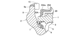
図23および図24は、この発明のさらに他の実施形態を示す。このセンサ付車輪用軸受では、図1ないし図13に示す第1の実施形態において、外方部材1の外周面に設けた保護カバー29Aを次のように構成したものである。この例では、保護カバー29Aは、第1の実施形態と同じくセンサ組立部品31および外方部材1の外周を覆う筒状の部材であるが、その外径がアウトボード側からインボード側に向けて段階的に拡径する形状とされ、インボード側端が外方部材1のフランジ1aの外径面に嵌合させられる。保護カバー29Aのアウトボード側端には、その開口縁に沿って環状の弾性体からなるリップ部35Aが設けられ、このリップ部35Aが外方部材1の外周面に当接させられる。これにより、保護カバー29Aのアウトボード側端と外方部材1の外周面との間、および保護カバー29Aのインボード側端と外方部材1のフランジ1aの外径面との間が密封され、アウトボード側端から保護カバー29A内への泥水・塩水等の浸入を確実に防止できる。その結果、外部環境の影響によるセンサの故障を確実に防止して、荷重検出を正確に行うことができる。
23 and 24 show still another embodiment of the present invention. In this sensor-equipped wheel bearing, in the first embodiment shown in FIGS. 1 to 13, the
前記リップ部35Aを構成する弾性体としてはゴム材料が望ましい。これにより、リップ部35Aによる保護カバー29Aのアウトボード側端での密封性を確実なものとすることができる。このほか、リップ部35Aを保護カバー29Aに一体形成しても良い。ここでは、図24に拡大断面図で示すように、リップ部35Aを、先端がアウトボード側に向かって次第に縮径して延びる形状としている。これにより、アウトボード側端から保護カバー29A内への泥水・塩水等の浸入をより確実に防止できる。また、リップ部35Aには、その一部を保護カバー29Aの外周面の一部まで延長してカバー外周面被覆部分35Aaが形成されている。これにより、保護カバー29Aの外周面におけるアウトボード側端において、カバー外周面被覆部分35Aaからなる壁が外径側に張り出すことになり、この壁によりリップ部35Aが外方部材1の外周面に当接している部分へ泥水・塩水等が流れ込むのを阻止でき、保護カバー29A内への泥水・塩水等の浸入をより確実に防止できる。カバー外周面被覆部分35Aaは、リップ部35Aを、保護カバー29Aの外周面へ取付ける場合は、その取付けに必要な強度を得るために保護カバー29Aの外周面に位置させる範囲よりもさらにインボード側へ延びて設ける。
As the elastic body constituting the
保護カバー29Aは、例えば耐食性を有する鋼板をプレス加工して成形される。これにより、保護カバー29Aが外部環境により腐食するのを防止できる。このほか、鋼板をプレス加工して保護カバー29Aを成形し、その表面に金属メッキまたは塗装処理を施しても良い。この場合も、保護カバー29Aが外部環境により腐食するのを防止できる。保護カバー29Aの材質は、このほかプラスチックやゴムであっても良い。
The
この実施形態におけるその他の構成、効果は、図1〜図13と共に説明した第1の実施形態と同様である。なお、この実施形態、および以下の各実施形態においても、図14と共に前述した表面処理層38を設けても良い。
Other configurations and effects in this embodiment are the same as those in the first embodiment described with reference to FIGS. In this embodiment and each of the following embodiments, the
図25および図26は、この発明のさらに他の実施形態を示す。このセンサ付車輪用軸受では、図23,図24に示す実施形態において、保護カバー29Aのアウトボード側端に設けたリップ部35Aのカバー外周面被覆部分35Aaの外周面を、図26に拡大断面図で示すようにアウトボード側に向かって拡径する傾斜面としている。その他の構成は図23,図24の実施形態の場合と同様である。
25 and 26 show still another embodiment of the present invention. In this sensor-equipped wheel bearing, in the embodiment shown in FIGS. 23 and 24, the outer peripheral surface of the cover outer peripheral surface covering portion 35Aa of the
このように、リップ部35Aのカバー外周面被覆部分35Aaの外周面を、アウトボード側に向かって拡径する傾斜面とすることにより、リップ部35Aが外方部材1の外周面に当接している部分へ泥水・塩水等が流れ込むのを阻止でき、保護カバー29A内への泥水・塩水等の浸入をより確実に防止できる。
In this way, by forming the outer peripheral surface of the cover outer peripheral surface covering portion 35Aa of the
図27および図28は、この発明のさらに他の実施形態を示す。このセンサ付車輪用軸受では、図23,図24に示す実施形態において、保護カバー29Aのアウトボード側端を外方部材1よりもアウトボード側に突出させ、そのアウトボード側端と、回転側部材である内方部材2との間に非接触シール隙間39A、すなわちラビリンスシールを形成している。非接触シール隙間39Aは、前述のように内方部材2と外方部材1との相対回転が生じている状態で、水等の浸入が防止される程度の狭い隙間である。ここでは、図28に拡大断面図で示すように、保護カバー29Aのアウトボード側端を内方部材2のハブフランジ9aのインボード側を向く側面近傍まで突出させ、その先端から内径側に折り曲げられインボード側へ向かう折り曲げ部29Aaを形成し、さらにその折り曲げ部29Aaの先端から内径側に向けて折り曲げられた内側折り曲げ部29Abを形成し、この内側折り曲げ部29Abにリップ部35Aを一体に設けている。その他の構成は図23,図24の実施形態の場合と同様である。
27 and 28 show still another embodiment of the present invention. In the sensor-equipped wheel bearing, in the embodiment shown in FIGS. 23 and 24, the outboard side end of the
このように、保護カバー29Aのアウトボード側端と内方部材2との間に非接触シール隙間39Aを形成することにより、保護カバー29Aのアウトボード側端における外方部材1との間のシールが、リップ部35Aの外方部材1の外周面への当接と、保護カバー29Aのアウトボード側端と内方部材2のハブフランジ9aとの間に形成される非接触シール39Aとによる二重の密閉構造でなされるので、アウトボード側でのシールがより確実なものとなり、外部環境の影響によるセンサの故障をさらに確実に防止して、荷重検出を正確に行うことができる。
In this way, by forming the
図29および図30は、この発明のさらに他の実施形態を示す。このセンサ付車輪用軸受では、図23および図24に示す実施形態において、保護カバー29Aのアウトボード側端の折り曲げ部29Aaを、図30に拡大断面図で示すようにインボード側に向けて縮径傾斜する形状としている。その他の構成は図23および図24に示す実施形態の場合と同様である。
29 and 30 show still another embodiment of the present invention. In the wheel bearing with sensor, in the embodiment shown in FIGS. 23 and 24, the bent portion 29Aa at the end of the outboard side of the
このように、保護カバー29Aのアウトボード側端の折り曲げ部29Aaをインボード側に向けて縮径傾斜する形状とすることにより、非接触シール隙間39Aから外方部材1のアウトボード側端に浸入してきた泥水・塩水等が前記折り曲げ部29Aaの傾斜面に沿って非接触シール隙間39Aから外側に向けて排出し易くなり、保護カバー29Aのアウトボード側端でのシール性がさらに向上する。
In this way, the bent portion 29Aa at the end of the outboard side of the
図31および図32は、この発明のさらに他の実施形態を示す。このセンサ付車輪用軸受では、図23および図24に示す実施形態において、保護カバー29Aのアウトボード側端の小径筒部29sと外方部材1の外周との間に、シール部材としてOリング35Bを介在させている。Oリング35Bは、図32に拡大断面図で示すように、外方部材1の外周面に設けられた環状のシール取付溝内に嵌め込んで取り付けてある。その他の構成は図23および図24に示す実施形態の場合と同様である。
このようにシール部材としてOリング35Bを設けた場合も、保護カバー29Aのアウトボード側端から保護カバー29A内への泥水・塩水等の浸入を確実に防止できて、外部環境の影響によるセンサの故障を確実に防止して、荷重検出を正確に行うことができる。
31 and 32 show still another embodiment of the present invention. In this embodiment of the wheel bearing with sensor, in the embodiment shown in FIGS. 23 and 24, an O-
As described above, even when the O-
図33および図34は、この発明のさらに他の実施形態を示す。このセンサ付車輪用軸受では、図23,図24に示す実施形態において、保護カバー29Aのアウトボード側端に設けたリップ部35Aを、回転側部材である内方部材2の表面に当接させている。具体的には、図34に拡大断面図で示すように保護カバー29Aのアウトボード側端を外方部材1よりもアウトボード側に突出させ、内方部材2の構成部品であるハブ輪9のハブフランジ9aのインボード側を向く側面に前記リップ部35Aを当接させている。その他の構成は図23、図24に示す実施形態の場合と同様である。
33 and 34 show still another embodiment of the present invention. In the sensor-equipped wheel bearing, in the embodiment shown in FIGS. 23 and 24, the
このように、保護カバー29Aのアウトボード側端に設けたリップ部35Aを内方部材2のハブフランジ9aに当接させた場合にも、保護カバー29Aのアウトボード側端から保護カバー29A内への泥水・塩水等の浸入を確実に防止できるので、外部環境の影響によるセンサの故障を確実に防止して、荷重検出を正確に行うことができる。また、この場合には、外方部材1と内方部材2の間に形成される軸受空間のアウトボード側端も密封されることになるので、アウトボード側のシール7を省略することも可能である。
As described above, even when the
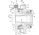
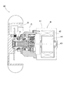
図35は、図1〜図13に示した第1の実施形態のセンサ付車輪用軸受Aを搭載したインホイール型モータ内蔵車輪用軸受装置の概要を示す断面図である。このインホイール型モータ内蔵車輪用軸受装置は、駆動輪40のハブを回転自在に支持する前記センサ付車輪用軸受Aと、回転駆動源としての電気モータBと、この電気モータBの回転を減速してハブに伝達する減速機Cと、ハブに制動力を与えるブレーキDとを、駆動輪40の中心軸上に配置したものである。電気モータBは、筒状のケーシング41に固定したステータ42と出力軸43に取付けたロータ44との間にラジアルギャップを設けたラジアルギャップ型のものである。減速機Cはサイクロイド減速機として構成されている。
なお、図35では、図1〜図13に示した実施形態のセンサ付車輪用軸受Aを搭載した例を示したが、これに限らずこの発明の他の実施形態のセンサ付車輪用軸受を用いた場合にも、同様の効果を上げることができる。
FIG. 35 is a cross-sectional view showing an outline of an in-wheel motor-equipped wheel bearing device equipped with the sensor-equipped wheel bearing A according to the first embodiment shown in FIGS. 1 to 13. This in-wheel type motor-integrated wheel bearing device includes a sensor-equipped wheel bearing A that rotatably supports a hub of the
In addition, in FIG. 35, although the example which mounts the wheel bearing A with a sensor of embodiment shown in FIGS. 1-13 was shown, not only this but the wheel bearing with sensor of other embodiment of this invention is shown. Similar effects can be achieved when used.
このように、この発明の前記いずれかの構成のセンサ付車輪用軸受Aをインホイール型モータ内蔵車輪用軸受装置の車輪用軸受として用いた場合には、外部環境の影響によるセンサの故障を防止して、車輪用軸受やタイヤ接地面に作用する荷重を長期にわたり正確に検出できるインホイール型モータ内蔵車輪用軸受装置とすることができる。 Thus, when the sensor-equipped wheel bearing A according to any one of the configurations of the present invention is used as a wheel bearing of a wheel bearing device with a built-in in-wheel motor, sensor failure due to the influence of the external environment is prevented. Thus, an in-wheel motor-equipped wheel bearing device that can accurately detect the load acting on the wheel bearing and the tire ground contact surface over a long period of time can be obtained.
上記各実施形態では第3世代型の車輪用軸受に適用した場合につき説明したが、この発明は、軸受部分とハブとが互いに独立した部品となる第1または第2世代型の車輪用軸受や、内方部材の一部が等速ジョイントの外輪で構成される第4世代型の車輪用軸受にも適用でき、さらに各世代形式のテーパころタイプの車輪用軸受にも適用することができる。また、外方部材が回転側部材となる車輪用軸受にも適用することができる。その場合、内方部材の外周にセンサユニットを設ける。 In each of the above embodiments, the case where the present invention is applied to a third generation type wheel bearing has been described. However, the present invention relates to a first or second generation type wheel bearing in which the bearing portion and the hub are independent parts. Further, the present invention can be applied to a fourth generation type wheel bearing in which a part of the inner member is constituted by an outer ring of a constant velocity joint, and can also be applied to a tapered roller type wheel bearing of each generation type. Further, the present invention can also be applied to a wheel bearing in which the outer member is a rotation side member. In that case, a sensor unit is provided on the outer periphery of the inner member.
1…外方部材
1a…車体取付用フランジ
2…内方部材
3,4…転走面
5…転動体
20…荷重検出用センサ部
21…歪み発生部材
21a…接触固定部21b…切欠き部
21d…屈曲部
22,22A,22B…歪みセンサ
29,29A…保護カバー
31…センサ組立品
32…推定手段
35,35A…リップ部〈シール部材〉
35B…Oリング(シール部材〉
38…表面処理層
39,39A…非接触シール隙間
DESCRIPTION OF
35B ... O-ring (seal member)
38 ... Surface treatment layers 39, 39A ... Non-contact seal gap
Claims (37)
上記外方部材および内方部材のうちの固定側部材に、この固定側部材に接触して固定される2つ以上の接触固定部を有する歪み発生部材、およびこの歪み発生部材に取付けられてこの歪み発生部材の歪みを検出する2つ以上のセンサからなる荷重検出用センサ部を複数設けてなるセンサ組立品を備えたセンサ付車輪用軸受であって、
前記2つ以上のセンサの出力信号により、車輪用軸受に作用する荷重を推定する推定手段を設け、
前記複数の荷重検出用センサ部の歪み発生部材を、これら複数の荷重検出用センサ部に渡って連続した1つの帯状の歪み発生部材とし、この帯状の歪み発生部材における前記2つ以上の接触固定部を、前記固定側部材の外径面の同一軸方向位置でかつ円周方向に互いに離間した位置となるように配置し、
複数の荷重検出用センサ部を固定側部材の外周を囲む筒状の保護カバーで覆い、この保護カバーの軸方向のいずれか一端で前記固定側部材の外周に嵌合させ、他端の開口縁に弾性体からなる環状のシール部材を設け、このシール部材を前記固定側部材の表面、または上記外方部材および内方部材のうちの回転側部材の表面に接触させた、
ことを特徴とするセンサ付車輪用軸受。 An outer member having a double row rolling surface formed on the inner periphery, an inner member having a rolling surface facing the rolling surface formed on the outer periphery, and interposed between the opposing rolling surfaces of both members A double row rolling element, and a wheel bearing for rotatably supporting the wheel with respect to the vehicle body,
A strain generating member having two or more contact fixing portions fixed to the fixed side member of the outer member and the inner member in contact with the fixed side member, and attached to the strain generating member. A sensor-equipped wheel bearing provided with a sensor assembly in which a plurality of load detection sensor portions including two or more sensors for detecting strain of a strain generating member are provided,
Estimating means for estimating a load acting on the wheel bearing is provided based on output signals of the two or more sensors,
The strain generating members of the plurality of load detecting sensor portions are used as one belt-like strain generating member continuous over the plurality of load detecting sensor portions, and the two or more contact fixings in the belt-shaped strain generating members are performed. The parts are arranged so as to be at the same axial position on the outer diameter surface of the fixed side member and at positions separated from each other in the circumferential direction,
A plurality of load detection sensors are covered with a cylindrical protective cover that surrounds the outer periphery of the fixed member, and is fitted to the outer periphery of the fixed member at one end in the axial direction of the protective cover. Provided with an annular sealing member made of an elastic body, and this sealing member was brought into contact with the surface of the stationary member, or the surface of the rotating member of the outer member and the inner member,
The wheel bearing with a sensor characterized by the above-mentioned.
前記帯状の歪み発生部材における前記3つの接触固定部を、前記固定側部材の外径面の同一軸方向位置でかつ円周方向に互いに離間した位置となるように配置し、隣り合う前記接触固定部の間隔または隣り合う前記センサの前記固定側部材の外径面の円周方向についての間隔を、転動体の配列ピッチの{1/2+n(n:整数)}倍またはこれらの値に近似した値とし、前記推定手段は、前記2つのセンサの出力信号の差分により、車輪用軸受に作用する荷重を推定するセンサ付車輪用軸受。 In any one of Claims 1 thru | or 28, the contact fixing | fixed part of the said distortion generation member in the said sensor part for load detection is three,
The three contact fixing portions of the belt-shaped strain generating member are arranged so as to be in the same axial direction position on the outer diameter surface of the fixed side member and spaced apart from each other in the circumferential direction, and the adjacent contact fixing portions. The interval in the circumferential direction of the outer diameter surface of the fixed side member of the sensor adjacent to each other or the adjacent sensor is {1/2 + n (n: integer)} times the arrangement pitch of the rolling elements or approximate to these values The sensor-equipped wheel bearing is configured to estimate a load acting on the wheel bearing based on a difference between output signals of the two sensors.
Priority Applications (5)
| Application Number | Priority Date | Filing Date | Title |
|---|---|---|---|
| JP2012104317A JP2012255544A (en) | 2011-05-16 | 2012-05-01 | Sensor-equipped wheel bearing |
| EP12782455.5A EP2708865B1 (en) | 2011-05-09 | 2012-05-08 | Sensor-equipped wheel bearing |
| CN201280022558.9A CN103502786B (en) | 2011-05-09 | 2012-05-08 | Sensor-equipped wheel bearing |
| US14/115,668 US9011013B2 (en) | 2011-05-09 | 2012-05-08 | Sensor-equipped wheel bearing |
| PCT/JP2012/061713 WO2012153721A1 (en) | 2011-05-09 | 2012-05-08 | Sensor-equipped wheel bearing |
Applications Claiming Priority (3)
| Application Number | Priority Date | Filing Date | Title |
|---|---|---|---|
| JP2011108949 | 2011-05-16 | ||
| JP2011108949 | 2011-05-16 | ||
| JP2012104317A JP2012255544A (en) | 2011-05-16 | 2012-05-01 | Sensor-equipped wheel bearing |
Publications (1)
| Publication Number | Publication Date |
|---|---|
| JP2012255544A true JP2012255544A (en) | 2012-12-27 |
Family
ID=47527275
Family Applications (1)
| Application Number | Title | Priority Date | Filing Date |
|---|---|---|---|
| JP2012104317A Pending JP2012255544A (en) | 2011-05-09 | 2012-05-01 | Sensor-equipped wheel bearing |
Country Status (1)
| Country | Link |
|---|---|
| JP (1) | JP2012255544A (en) |
Cited By (1)
| Publication number | Priority date | Publication date | Assignee | Title |
|---|---|---|---|---|
| JP2017145953A (en) * | 2016-02-19 | 2017-08-24 | Ntn株式会社 | Wheel bearing device |
Citations (7)
| Publication number | Priority date | Publication date | Assignee | Title |
|---|---|---|---|---|
| JPH0632735U (en) * | 1992-09-30 | 1994-04-28 | エヌティエヌ株式会社 | Rolling bearing with sensor |
| JP2007032705A (en) * | 2005-07-27 | 2007-02-08 | Jtekt Corp | Roller bearing device with sensor, and strain sensor |
| WO2009125583A1 (en) * | 2008-04-10 | 2009-10-15 | Ntn株式会社 | Wheel bearing with sensor |
| JP2010127744A (en) * | 2008-11-27 | 2010-06-10 | Jtekt Corp | Displacement sensor apparatus and roller bearing apparatus |
| JP2010139303A (en) * | 2008-12-10 | 2010-06-24 | Ntn Corp | Sensor-equipped bearing for wheel |
| JP2010180895A (en) * | 2009-02-03 | 2010-08-19 | Ntn Corp | Sensor-equipped bearing for wheel |
| WO2011046095A1 (en) * | 2009-10-14 | 2011-04-21 | Ntn株式会社 | Wheel bearing with sensor |
-
2012
- 2012-05-01 JP JP2012104317A patent/JP2012255544A/en active Pending
Patent Citations (7)
| Publication number | Priority date | Publication date | Assignee | Title |
|---|---|---|---|---|
| JPH0632735U (en) * | 1992-09-30 | 1994-04-28 | エヌティエヌ株式会社 | Rolling bearing with sensor |
| JP2007032705A (en) * | 2005-07-27 | 2007-02-08 | Jtekt Corp | Roller bearing device with sensor, and strain sensor |
| WO2009125583A1 (en) * | 2008-04-10 | 2009-10-15 | Ntn株式会社 | Wheel bearing with sensor |
| JP2010127744A (en) * | 2008-11-27 | 2010-06-10 | Jtekt Corp | Displacement sensor apparatus and roller bearing apparatus |
| JP2010139303A (en) * | 2008-12-10 | 2010-06-24 | Ntn Corp | Sensor-equipped bearing for wheel |
| JP2010180895A (en) * | 2009-02-03 | 2010-08-19 | Ntn Corp | Sensor-equipped bearing for wheel |
| WO2011046095A1 (en) * | 2009-10-14 | 2011-04-21 | Ntn株式会社 | Wheel bearing with sensor |
Cited By (1)
| Publication number | Priority date | Publication date | Assignee | Title |
|---|---|---|---|---|
| JP2017145953A (en) * | 2016-02-19 | 2017-08-24 | Ntn株式会社 | Wheel bearing device |
Similar Documents
| Publication | Publication Date | Title |
|---|---|---|
| WO2012153721A1 (en) | Sensor-equipped wheel bearing | |
| WO2011046095A1 (en) | Wheel bearing with sensor | |
| US7882752B2 (en) | Sensor-equipped bearing for wheel | |
| JP5274343B2 (en) | Wheel bearing with sensor | |
| US8596146B2 (en) | Sensor-equipped bearing for wheel | |
| US8439568B2 (en) | Wheel support bearing assembly equipped with sensor | |
| WO2010044228A1 (en) | Sensor-equipped bearing for wheel | |
| WO2011148846A1 (en) | Sensor-equipped wheel bearing | |
| EP1939598A1 (en) | Sensor-equipped bearing for wheel | |
| JP5171589B2 (en) | Wheel bearing with sensor | |
| JP5409336B2 (en) | Wheel bearing with sensor | |
| JP5153373B2 (en) | Wheel bearing with sensor | |
| JP5615033B2 (en) | In-wheel motor drive device | |
| JP2012255544A (en) | Sensor-equipped wheel bearing | |
| JP5511304B2 (en) | Wheel bearing with sensor | |
| JP5571460B2 (en) | Wheel bearing with sensor | |
| JP6067241B2 (en) | Wheel bearing with sensor | |
| JP5484204B2 (en) | Wheel bearing with sensor | |
| JP5571455B2 (en) | Wheel bearing with sensor | |
| JP2012242273A (en) | Wheel bearing with sensors | |
| JP2010242921A (en) | Wheel bearing with sensor | |
| JP2010180895A (en) | Sensor-equipped bearing for wheel | |
| JP2010138958A (en) | Bearing for wheel with sensor | |
| JP2011252791A (en) | Wheel bearing with sensor | |
| JP2014001822A (en) | Wheel bearing device with sensor |
Legal Events
| Date | Code | Title | Description |
|---|---|---|---|
| A621 | Written request for application examination |
Free format text: JAPANESE INTERMEDIATE CODE: A621 Effective date: 20150309 |
|
| A131 | Notification of reasons for refusal |
Free format text: JAPANESE INTERMEDIATE CODE: A131 Effective date: 20151222 |
|
| A521 | Written amendment |
Free format text: JAPANESE INTERMEDIATE CODE: A523 Effective date: 20160217 |
|
| A02 | Decision of refusal |
Free format text: JAPANESE INTERMEDIATE CODE: A02 Effective date: 20160719 |