JP2012255258A - Method for repairing existing lean-to roof and lean-to roof structure - Google Patents
Method for repairing existing lean-to roof and lean-to roof structure Download PDFInfo
- Publication number
- JP2012255258A JP2012255258A JP2011127605A JP2011127605A JP2012255258A JP 2012255258 A JP2012255258 A JP 2012255258A JP 2011127605 A JP2011127605 A JP 2011127605A JP 2011127605 A JP2011127605 A JP 2011127605A JP 2012255258 A JP2012255258 A JP 2012255258A
- Authority
- JP
- Japan
- Prior art keywords
- roof
- shed
- lean
- foundation
- column
- Prior art date
- Legal status (The legal status is an assumption and is not a legal conclusion. Google has not performed a legal analysis and makes no representation as to the accuracy of the status listed.)
- Granted
Links
Images


Abstract
Description
本発明は、既存下屋の改修方法および下屋構造に関する。 The present invention relates to a method for repairing an existing shed and a shed structure.
鉄骨造の工場や体育館などでは、母屋の脇に下屋が設けられている場合がある(例えば、特許文献1参照)。
このような下屋は、母屋から張り出された下屋屋根と、この下屋屋根を支持する下屋柱とを備えて構成されている。
In steel-frame factories, gymnasiums, and the like, there is a case where a lower house is provided beside the main building (see, for example, Patent Document 1).
Such a shed is configured to include a shed roof that protrudes from the main house and a shed pillar that supports the shed roof.
下屋は、軽量な付属施設として計画されているため、下屋の柱脚部の基礎は母屋(工場や体育館等の本体)の主フレームの基礎と一体化されておらず、また、水平耐力用のブレースは、比較的簡易な鉄筋ブレースで構成されていることが多い。 Because the lower house is planned as a lightweight accessory facility, the foundation of the base of the lower house is not integrated with the foundation of the main frame of the main building (the main body of the factory, gymnasium, etc.), and the horizontal strength The braces for use are often composed of relatively simple rebar braces.
そのため、下屋101は主フレーム102とは異なる変形挙動を示し、地震時等の大きな外力が作用した場合には、下屋101の外装材110が面外に変形するおそれがある(図5参照)。
Therefore, the
本発明は、前記の問題点を解決するものであり、母屋と下屋との地震時の変形挙動を概ね同一とすることを可能とした、既存下屋の改修方法および下屋構造を提案することを課題とする。 The present invention solves the above-described problems, and proposes a method for repairing an existing shed and a shed structure that can make the deformation behavior of the main shed and the shed at the time of an earthquake substantially the same. This is the issue.
前記課題を解決するために、本発明の既存下屋の改修方法は、母屋から張り出す下屋屋根と、前記下屋屋根の先端部を支持する下屋柱とを備える既存下屋の改修方法であって、前記下屋屋根の先端部と前記母屋の柱脚部とをつなぐブレースを配置するとともに、前記下屋柱の脚部を基礎から分離することを特徴としている。 In order to solve the above-mentioned problem, a method for renovating an existing shed according to the present invention is a method for renovating an existing shed comprising a shed roof protruding from a main building and a shed pillar that supports the tip of the shed roof. And the brace which connects the front-end | tip part of the said bottom roof and the column base part of the said main building is arrange | positioned, and the leg part of the said bottom column is isolate | separated from the foundation.
かかる既存下屋の改修方法によれば、下屋柱の水平移動が許容されるようになるので、母屋と下屋との変形挙動の差を少なくすることが可能となる。なお、ブレースにより下屋屋根の先端部が支持されるようになるので、下屋柱の脚部を基礎から分離しても、下屋屋根が不安定になることはない。 According to the method for renovating the existing shed, the horizontal movement of the shed column is allowed, so that the difference in deformation behavior between the main shed and the shed can be reduced. In addition, since the front-end | tip part of a lower house roof comes to be supported by a brace, even if the leg part of a lower house pillar is isolate | separated from a foundation, a lower house roof will not become unstable.
前記下屋柱の脚部と前記基礎との間に摺動部材を介設すれば、下屋柱の水平移動を許容するとともに、基礎への軸力の伝達が可能となる。 If a sliding member is interposed between the leg portion of the lower column and the foundation, the horizontal movement of the lower column is allowed and the axial force can be transmitted to the foundation.
また、本発明の下屋構造は、母屋から張り出す下屋屋根と、前記下屋屋根の先端部を支持する下屋柱と、前記下屋屋根の先端部と前記母屋の柱脚部とをつなぐブレースとを備え、前記下屋柱は基礎に対して水平方向に移動可能であることを特徴としている。 Further, the lower roof structure of the present invention includes a lower roof extending from the main roof, a lower pillar supporting the front end of the lower roof, a front end of the lower roof, and a column base of the main roof. The lower column is movable in the horizontal direction with respect to the foundation.
かかる下屋構造によれば、母屋との変形挙動の差が少ない下屋を構成することができる。また、下屋屋根は、ブレースにより先端部が支持されているため、安定している。 According to such a shed structure, a shed having a small difference in deformation behavior from the main shed can be configured. Moreover, since the front-end | tip part is supported by the brace, the lower roof is stable.
本発明の既存下屋の改修方法および下屋構造によれば、母屋の主フレームと下屋との地震時の変形挙動を概ね同一にすることが可能となる。 According to the repair method and the roof structure of the existing roof of the present invention, it is possible to make the deformation behavior of the main frame of the main roof and the roof at the time of an earthquake substantially the same.
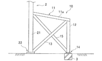
本発明の実施の形態に係る下屋構造10は、体育館や構造建物等である母屋2の付随施設として形成された下屋(既存下屋)1を改修したものであり、図1に示すように、下屋屋根11と、下屋柱12と、ブレース13とを備えている。
A
下屋1の規模や形状は限定されるものではなく、下屋1の使用目的等に応じて適宜設定されている。
また、母屋2の構造や使用目的等も限定されるものではない。
The scale and shape of the lower house 1 are not limited, and are appropriately set according to the purpose of use of the lower house 1.
Further, the structure and purpose of use of the
下屋屋根11は、母屋2から張り出した既存の部材である。
下屋屋根11の基端部は母屋2の構造体(母屋柱(母屋2の柱)21や梁等)に固定されているとともに、下屋屋根11の先端部は、下屋柱12に固定されている。
The
The base end of the
下屋屋根11の構成は限定されるものではないが、本実施形態では、枠状に形成された梁部材11aと、枠状の梁部材の開口部を覆う版状の屋根部材(図示省略)とにより構成されている。
なお、梁部材を構成する材料は限定されるものではなく、例えば、アングル材、チャンネル材、H形鋼等の形鋼の他、木材であってもよい。
Although the configuration of the
In addition, the material which comprises a beam member is not limited, For example, timber other than shape steel, such as an angle material, a channel material, H-section steel, may be sufficient.
下屋柱12は、摺動部材14を介して基礎3に立設されていて、下屋屋根11の先端部を支持している。基礎3は、下屋柱12の下方に設けられており、母屋2の基礎とは独立している。
The
本実施形態の下屋柱12は、基礎3に対して水平方向に移動可能であるとともに、基礎3への軸力の伝達が可能に構成されている。
下屋柱12を構成する材料は限定されるものではなく、例えば、アングル材、チャンネル材、H形鋼等の形鋼の他、木材であってもよい。
The
The material constituting the
本実施形態では、図2に示すように、下屋柱12と基礎3との間に摺動部材14が介設されている。
In the present embodiment, as shown in FIG. 2, a sliding
本実施形態の摺動部材14は、下屋柱12の下端面に固定された上低摩擦板材14aと、基礎3の上端面に固定された下低摩擦板材14bとを備えている。
低摩擦板材14a,14bは、すべり支承であり、上低摩擦板材14aの下面と下低摩擦板材14bの上面とは面接触している。
The sliding
The
低摩擦板材14a,14b同士が当接した摺動部材14によれば、水平方向への摺動が可能となる。なお、下低摩擦板材14bは、上低摩擦板材14aよりも大きな面積を有していて、下屋柱12が水平移動した際も、上低摩擦板材14aとの当接状態を維持し、基礎3への軸力の伝達が可能である。
According to the sliding
なお、摺動部材14の構成は限定されるものではなく、例えば、ローラー部材や球状部材等を備えたものであってもよい。
In addition, the structure of the sliding
ブレース13は、下屋屋根11の先端部と母屋柱21の柱脚部22とをつなぐように配設された斜材である。
The
ブレース13には、地震時等において作用する圧縮力に対して十分な剛性耐力を備えたものを使用するものとし、例えば、アングル材やチャンネル材(Cチャンネルやコ字状チャンネル等)等の形鋼により構成する。
The
本実施形態では、下屋屋根11と母屋2との接合部と、下屋柱12の脚部とをつなぐ補助ブレース15を配置しているが、補助ブレース15は必要に応じて配置すればよく、省略してもよい。
In this embodiment, although the
次に、下屋構造10を形成するための、既存下屋の改修方法について説明する。
Next, the repair method of the existing shed for forming the
改修前の既存の下屋1は、図3の(a)に示すように、母屋2から張り出す下屋屋根11と、下屋屋根11の先端部を支持する下屋柱12と、引張筋交としての鉄筋ブレース16とを備えている。
下屋柱12の脚部は、ボルト31を介して基礎3にピン接合されている。
As shown in FIG. 3A, the existing shed 1 before renovation includes a
The legs of the
下屋1の改修は、まず、鉄筋ブレース16を撤去し、次いで、図3の(b)に示すように、鉄筋ブレース16よりも圧縮耐力の大きいブレース13で、下屋屋根11の先端部と母屋2の柱脚部22とをつなぐ。また、鉄筋ブレース16よりも圧縮耐力の大きい補助ブレース15で、下屋屋根11と母屋2との接合部と、下屋柱12の脚部とをつなぐ。
The renovation of the lower house 1 is performed by first removing the reinforcing
次に、図3の(c)に示すように、下屋柱12と基礎3とをつなぐボルト31を切断するとともに、下屋柱12と基礎3との間に介設されたベースモルタル32を撤去する。これにより、下屋柱12の脚部が基礎3から分離される。
Next, as shown in FIG. 3 (c), the
その後、図2に示すように、下屋柱12と基礎3との間に、摺動部材14を介設する。
このとき、上低摩擦板材14aは、接着剤14cにより下屋柱12の脚部に固定すればよく、また、下低摩擦板材14bは、グラウト14dを介して基礎3の上面に固定すればよい。
なお、摺動部材14(上低摩擦板材14aおよび下低摩擦板材14b)の固定方法は限定されるものではない。
Thereafter, as shown in FIG. 2, a sliding
At this time, the upper and lower
In addition, the fixing method of the sliding member 14 (the upper low friction board |
本実施形態の下屋構造10および既存下屋の改修方法によれば、下屋柱12の水平移動が許容されるようになるので、母屋2と下屋1との変形挙動の差を少なくすることが可能となる(図4の(a)および(b)参照)。そのため、母屋2と下屋1との挙動の差により下屋部分の外装が面外に変形して破損することを防止できる。
According to the
下屋屋根11の梁部材11aとブレース13によりトラス構造を形成することで、下屋1の鉛直剛性および水平剛性を高めて母屋2との一体化を図ることが可能となる。
By forming a truss structure with the
また、下屋1の自重を、ブレース13を介して母屋2の主フレーム(母屋柱21)に伝達することが可能となり、下屋柱12の脚部を基礎3から分離しても、下屋屋根11が不安定になることはない。そのため、下屋柱12の軸力の仮受けのための仮設支保部材を要することなく、下屋柱12の基礎3からの分離作業および摺動部材14の設置作業を実施することができる。
Further, the weight of the lower house 1 can be transmitted to the main frame (the main house pillar 21) of the
下屋柱12と基礎3との間に摺動部材14が介設されているため、下屋柱12の水平移動を許容するとともに、基礎への軸力の伝達が可能となり、下屋1の安定性が保持される。
Since the sliding
以上、本発明について、好適な実施形態について説明した。しかし、本発明は、前述の実施形態に限られず、前記の各構成要素については、本発明の趣旨を逸脱しない範囲で、適宜変更が可能である。 The preferred embodiments of the present invention have been described above. However, the present invention is not limited to the above-described embodiment, and the above-described constituent elements can be appropriately changed without departing from the spirit of the present invention.
例えば、前記実施形態では、既存の下屋1を改修して下屋構造10を形成する場合について説明したが、新設の下屋に対して、本発明の下屋構造10を採用してもよい。
For example, in the above-described embodiment, the case where the existing shed 1 is modified to form the
また、前記実施形態では、下屋柱12と基礎3との間に摺動部材14を介設する場合について説明したが、摺動部材14は必要に応じて配設すればよく、下屋柱12の軸力を基礎3で負担する必要が無い場合には摺動部材14の設置を省略してもよい。
Moreover, although the said embodiment demonstrated the case where the sliding
また、前記実施形態では、ブレース13を配置した後に下屋柱12を基礎3から分離したが、下屋柱12を基礎3から分離した後にブレース13を配置してもよい。
Moreover, in the said embodiment, although the
1 下屋(既存下屋)
10 下屋構造
11 下屋屋根
12 下屋柱
13 ブレース
14 摺動部材
2 母屋
21 母屋柱
22 脚部(柱脚部)
3 基礎
1 hut (existing shed)
DESCRIPTION OF
3 basics
Claims (3)
前記下屋屋根の先端部と前記母屋の柱脚部とをつなぐブレースを配置するとともに、前記下屋柱の脚部を基礎から分離することを特徴とする既存下屋の改修方法。 A renovation method for an existing shed comprising a shed roof protruding from a main shed and a shed pillar supporting the tip of the shed roof,
A method for refurbishing an existing shed, wherein a brace for connecting a front end portion of the lower shed roof and a column base portion of the main building is disposed, and a leg portion of the lower shed column is separated from a foundation.
前記下屋屋根の先端部を支持する下屋柱と、
前記下屋屋根の先端部と前記母屋の柱脚部とをつなぐブレースと、を備え、
前記下屋柱は、基礎に対して水平方向に移動可能であることを特徴とする、下屋構造。 A lower roof that protrudes from the main house,
A lower pillar supporting the front end of the lower roof;
A brace connecting the tip of the lower roof and the column base of the main house,
A lower house structure, wherein the lower house pillar is movable in a horizontal direction with respect to a foundation.
Priority Applications (1)
| Application Number | Priority Date | Filing Date | Title |
|---|---|---|---|
| JP2011127605A JP5592310B2 (en) | 2011-06-07 | 2011-06-07 | Renovation method of existing shed and shed structure |
Applications Claiming Priority (1)
| Application Number | Priority Date | Filing Date | Title |
|---|---|---|---|
| JP2011127605A JP5592310B2 (en) | 2011-06-07 | 2011-06-07 | Renovation method of existing shed and shed structure |
Publications (2)
| Publication Number | Publication Date |
|---|---|
| JP2012255258A true JP2012255258A (en) | 2012-12-27 |
| JP5592310B2 JP5592310B2 (en) | 2014-09-17 |
Family
ID=47527058
Family Applications (1)
| Application Number | Title | Priority Date | Filing Date |
|---|---|---|---|
| JP2011127605A Expired - Fee Related JP5592310B2 (en) | 2011-06-07 | 2011-06-07 | Renovation method of existing shed and shed structure |
Country Status (1)
| Country | Link |
|---|---|
| JP (1) | JP5592310B2 (en) |
Citations (5)
| Publication number | Priority date | Publication date | Assignee | Title |
|---|---|---|---|---|
| JPH1150695A (en) * | 1997-08-01 | 1999-02-23 | Taisei Corp | Base isolating mechanism for stairs in base isolation structure |
| JP2000073619A (en) * | 1998-08-28 | 2000-03-07 | Hazama Gumi Ltd | Support structure of incidental part in base isolation building |
| JP2000352221A (en) * | 1999-06-10 | 2000-12-19 | Sekisui Chem Co Ltd | Support structure of overhang plate of base isolation building |
| JP2001073473A (en) * | 1999-03-09 | 2001-03-21 | Sekisui Chem Co Ltd | Doorway structure for base-isolated building, unit-type base-isolated building with the doorway structure, and building unit |
| JP2009174282A (en) * | 2008-01-28 | 2009-08-06 | Takenaka Komuten Co Ltd | Seismic strengthening method |
-
2011
- 2011-06-07 JP JP2011127605A patent/JP5592310B2/en not_active Expired - Fee Related
Patent Citations (5)
| Publication number | Priority date | Publication date | Assignee | Title |
|---|---|---|---|---|
| JPH1150695A (en) * | 1997-08-01 | 1999-02-23 | Taisei Corp | Base isolating mechanism for stairs in base isolation structure |
| JP2000073619A (en) * | 1998-08-28 | 2000-03-07 | Hazama Gumi Ltd | Support structure of incidental part in base isolation building |
| JP2001073473A (en) * | 1999-03-09 | 2001-03-21 | Sekisui Chem Co Ltd | Doorway structure for base-isolated building, unit-type base-isolated building with the doorway structure, and building unit |
| JP2000352221A (en) * | 1999-06-10 | 2000-12-19 | Sekisui Chem Co Ltd | Support structure of overhang plate of base isolation building |
| JP2009174282A (en) * | 2008-01-28 | 2009-08-06 | Takenaka Komuten Co Ltd | Seismic strengthening method |
Also Published As
| Publication number | Publication date |
|---|---|
| JP5592310B2 (en) | 2014-09-17 |
Similar Documents
| Publication | Publication Date | Title |
|---|---|---|
| CN104912190A (en) | Dry type joggle frame structure | |
| US10480172B2 (en) | Building structure, building, and building construction method | |
| JP6769549B2 (en) | Beam joining method, beam joining structure, and support members | |
| JP6052252B2 (en) | Cantilever beam support structure | |
| JP2008111331A (en) | Building with joint metal | |
| JP5645334B2 (en) | Structure dismantling system | |
| JP6128095B2 (en) | Carry-out beam support structure | |
| JP5592310B2 (en) | Renovation method of existing shed and shed structure | |
| JP2010100990A (en) | Earthquake-resisting wall | |
| JP5400283B2 (en) | Building unit connection structure and unit building | |
| JP5840914B2 (en) | New and old building thatched roof method | |
| KR20120042239A (en) | Steel plate shear wall which columns bear only gravity load | |
| JP2011214280A (en) | Seismatic strengthening construction method and seismic strengthening frame for existing building | |
| JP6634259B2 (en) | Column and beam frame | |
| KR101825580B1 (en) | Steel and precast concrete hybrid beam | |
| JP6441689B2 (en) | How to install seismic isolation structures | |
| JP2014177783A (en) | Structure demolition system | |
| JP2010084477A (en) | Seismic control structure | |
| JP3212924U (en) | Fiber sheet reinforcement structure for wood main structural members | |
| JP6783038B2 (en) | Building structure | |
| JP2015098780A (en) | Existing building earthquake strengthening method and earthquake strengthening frame | |
| JP2007231596A (en) | Column base fixture, column base fixing structure and column base fixing method | |
| CN105275113A (en) | Rhombus steel grid shear wall structure | |
| JP2015227588A (en) | Structure | |
| JP7188094B2 (en) | roof structure |
Legal Events
| Date | Code | Title | Description |
|---|---|---|---|
| A621 | Written request for application examination |
Free format text: JAPANESE INTERMEDIATE CODE: A621 Effective date: 20130918 |
|
| A977 | Report on retrieval |
Free format text: JAPANESE INTERMEDIATE CODE: A971007 Effective date: 20140522 |
|
| TRDD | Decision of grant or rejection written | ||
| A01 | Written decision to grant a patent or to grant a registration (utility model) |
Free format text: JAPANESE INTERMEDIATE CODE: A01 Effective date: 20140715 |
|
| A61 | First payment of annual fees (during grant procedure) |
Free format text: JAPANESE INTERMEDIATE CODE: A61 Effective date: 20140731 |
|
| R150 | Certificate of patent or registration of utility model |
Ref document number: 5592310 Country of ref document: JP Free format text: JAPANESE INTERMEDIATE CODE: R150 |
|
| LAPS | Cancellation because of no payment of annual fees |