JP2012254167A - Pot washer - Google Patents
Pot washer Download PDFInfo
- Publication number
- JP2012254167A JP2012254167A JP2011128520A JP2011128520A JP2012254167A JP 2012254167 A JP2012254167 A JP 2012254167A JP 2011128520 A JP2011128520 A JP 2011128520A JP 2011128520 A JP2011128520 A JP 2011128520A JP 2012254167 A JP2012254167 A JP 2012254167A
- Authority
- JP
- Japan
- Prior art keywords
- cleaning liquid
- pan
- pot
- cleaning
- mounting table
- Prior art date
- Legal status (The legal status is an assumption and is not a legal conclusion. Google has not performed a legal analysis and makes no representation as to the accuracy of the status listed.)
- Granted
Links
- 239000007788 liquid Substances 0.000 claims abstract description 107
- 238000004140 cleaning Methods 0.000 claims description 127
- 238000002347 injection Methods 0.000 claims description 23
- 239000007924 injection Substances 0.000 claims description 23
- XLYOFNOQVPJJNP-UHFFFAOYSA-N water Substances O XLYOFNOQVPJJNP-UHFFFAOYSA-N 0.000 claims description 22
- 238000005507 spraying Methods 0.000 claims description 6
- 238000005406 washing Methods 0.000 abstract description 20
- 239000007921 spray Substances 0.000 description 9
- 238000001514 detection method Methods 0.000 description 6
- 239000000428 dust Substances 0.000 description 5
- 238000005192 partition Methods 0.000 description 4
- 238000010521 absorption reaction Methods 0.000 description 3
- 238000010411 cooking Methods 0.000 description 1
- 230000003247 decreasing effect Effects 0.000 description 1
- 230000000694 effects Effects 0.000 description 1
- 238000010438 heat treatment Methods 0.000 description 1
Images


Abstract
Description
本発明は、鍋の内面に向けて洗浄液を噴射して鍋を洗浄するための鍋洗浄装置に関するものである。 The present invention relates to a pan cleaning apparatus for cleaning a pan by spraying a cleaning liquid toward the inner surface of the pan.
従来より、飲食物を提供する店舗においては、調理で使用した鍋を洗浄するために鍋洗浄装置が使用されている(たとえば、特許文献1参照。)。 2. Description of the Related Art Conventionally, in stores that provide food and drink, a pan cleaning device is used to clean the pan used in cooking (for example, see Patent Document 1).
この従来の鍋洗浄装置は、ケーシングの内部に鍋を立てた状態で載置するとともに、立てた状態の鍋の内面へ向けて洗浄液を噴射して、鍋を洗浄するように構成している。 This conventional pot cleaning apparatus is configured to be placed in a state where a pot is set up in a casing, and to wash the pot by spraying a cleaning liquid toward the inner surface of the set up pot.
ところが、上記従来の鍋洗浄装置では、鍋を立てた状態で洗浄するように構成しているために、鍋の内面全体をむらなく洗浄することが困難であった。 However, since the conventional pan cleaning apparatus is configured to clean the pan in a standing state, it has been difficult to clean the entire inner surface of the pan evenly.
また、従来の鍋洗浄装置では、常に新規の洗浄液を鍋の内面へ向けて噴射するように構成しているために、洗浄液の使用量が多くなり、鍋洗浄装置の使用に際して多大なランニングコストを要していた。 In addition, since the conventional pot cleaning device is configured to always inject new cleaning liquid toward the inner surface of the pot, the amount of cleaning liquid used is increased, and a large running cost is required when using the pot cleaning apparatus. It was necessary.
そこで、請求項1に係る本発明では、鍋の内面に向けて洗浄液を噴射して鍋を洗浄するための鍋洗浄装置において、鍋を伏せた状態で載置する鍋載置台と、鍋載置台に載置された鍋の内面へ向けて洗浄液を噴射する洗浄液噴射機構とを有し、洗浄液噴射機構は、洗浄液を貯留する貯留槽に循環ポンプを収容して洗浄液を循環させて鍋の洗浄を行うとともに、貯留槽にオーバーフロー管を配設して、洗浄済みの洗浄液をオーバーフロー管から排出するように構成することにした。
Therefore, in the present invention according to
また、請求項2に係る本発明では、前記請求項1に係る本発明において、前記貯留槽に新規の洗浄液を補充する洗浄液補充機構を設け、洗浄液補充機構は、鍋載置台に載置された鍋の内面及び外面へ向けて補充する新規の洗浄液を噴射するように構成することにした。
Further, in the present invention according to
また、請求項3に係る本発明では、前記請求項2に係る本発明において、前記洗浄液補充機構は、貯留槽の水位が所定水位以下となった場合に新規の洗浄液を補充するように構成することにした。
Further, in the present invention according to
そして、本発明では、以下に記載する効果を奏する。 And in this invention, there exists an effect described below.
すなわち、本発明では、鍋の内面に向けて洗浄液を噴射して鍋を洗浄するための鍋洗浄装置において、鍋を伏せた状態で載置する鍋載置台と、鍋載置台に載置された鍋の内面へ向けて洗浄液を噴射する洗浄液噴射機構とを有し、洗浄液噴射機構は、洗浄液を貯留する貯留槽に循環ポンプを収容して洗浄液を循環させて鍋の洗浄を行うとともに、貯留槽にオーバーフロー管を配設して、洗浄済みの洗浄液をオーバーフロー管から排出するように構成しているために、伏せた状態の鍋の内面へ向けて洗浄液を噴射することで鍋の内面をむらなく洗浄することができ、また、洗浄液を循環して利用することで洗浄液の使用量を少なくして鍋洗浄装置のランニングコストを低減することができる。 That is, in the present invention, in the pan cleaning apparatus for cleaning the pan by spraying the cleaning liquid toward the inner surface of the pan, the pan mounting table mounted in a state where the pan is turned down, and the pan mounting table mounted A cleaning liquid injection mechanism that injects the cleaning liquid toward the inner surface of the pan, and the cleaning liquid injection mechanism accommodates a circulation pump in a storage tank that stores the cleaning liquid, circulates the cleaning liquid, and cleans the pot. Since the overflow pipe is arranged on the top and the washed cleaning liquid is discharged from the overflow pipe, the cleaning liquid is sprayed toward the inner surface of the pan in the face down state, so that the inner surface of the pan is not evenly distributed. It can wash | clean and can reduce the usage amount of a washing | cleaning liquid by circulating and using a washing | cleaning liquid, and can reduce the running cost of a pan washing apparatus.
特に、貯留槽に新規の洗浄液を補充する洗浄液補充機構を設け、洗浄液補充機構は、鍋載置台に載置された鍋の内面及び外面へ向けて補充する新規の洗浄液を噴射するように構成した場合には、鍋の内面及び外面を新規の洗浄液で良好に洗浄することができる。 In particular, the storage tank is provided with a cleaning liquid replenishing mechanism for replenishing a new cleaning liquid, and the cleaning liquid replenishing mechanism is configured to inject a new cleaning liquid to be replenished toward the inner surface and the outer surface of the pan placed on the pan mounting table. In this case, the inner and outer surfaces of the pan can be cleaned well with a new cleaning liquid.
また、貯留槽の水位が所定水位以下となった場合に新規の洗浄液を補充するように洗浄液補充機構を構成した場合には、貯留槽に貯留した洗浄液で鍋の内面を洗浄した後に続けて新規の洗浄液で鍋の内面及び外面をすすぐことができ、鍋全体を良好に洗浄することができる。 In addition, when the cleaning liquid replenishment mechanism is configured to replenish a new cleaning liquid when the water level in the storage tank falls below the predetermined water level, the cleaning tank stored in the storage tank is cleaned with the inner surface of the pan. The inner and outer surfaces of the pan can be rinsed with the cleaning liquid, and the entire pan can be cleaned well.
以下に、本発明に係る鍋洗浄装置の具体的な構成について図面を参照しながら説明する。 Below, the specific structure of the pan washing apparatus which concerns on this invention is demonstrated, referring drawings.
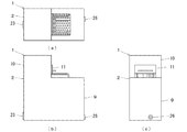
図1〜図4に示すように、鍋洗浄装置1は、ケーシング2の内部に、鍋3を伏せた状態で載置するための鍋載置台4と、鍋3に向けて洗浄液5を噴射するための洗浄液噴射機構6と、洗浄液5を補充するための洗浄液補充機構7と、これら洗浄液噴射機構6や洗浄液補充機構7を制御するための制御機構8とを収容している。
As shown in FIGS. 1 to 4, the
ケーシング2は、中空箱型状のケース本体9の後側上部にフード10を形成し、ケース本体9の前側上端部とフード10の前側部を開口するとともに、フード10の前側部に扉11を開閉自在に取付けている。
The
また、ケーシング2は、ケース本体9の内部に仕切壁12を取付けて、ケース本体9の内部を仕切壁12で前後に区画し、仕切壁12より後方側上部に洗浄液5を貯留するための貯留槽13を形成している。
In addition, the
鍋載置台4は、貯留槽13の開口部に左右一対の支持フレーム14,15を高さ調節可能に取付け、左右の支持フレーム14,15の上部に矩形枠状の枠フレーム16を取付け、枠フレーム16の上部に前後一対の門型の上部フレーム17,18を取付けるとともに、枠フレーム16の後側上部に左右一対のサイドフレーム19,20を取付けている。
The pan mounting table 4 has a pair of left and
そして、鍋載置台4は、支持フレーム14,15と枠フレーム16で鍋3を伏せた状態(上下反転させた状態)で保持するとともに、上部フレーム17,18とサイドフレーム19,20で鍋3の外方を覆うようにしている。
The pan mounting table 4 holds the
洗浄液噴射機構6は、ケーシング2の底部中央に貯留槽13に連通連結した循環ポンプ21を収容し、循環ポンプ21に上下に伸延する噴射ノズル22を連通連結し、噴射ノズル22の先端部を鍋載置台4の左右の支持フレーム14,15の間から上方へ向けて突出させている。
The cleaning
また、洗浄液噴射機構6は、ケーシング2の底部後方に排水口23を形成し、排水口23に貯留槽13の内部に収容したオーバーフロー管24を接続し、さらに、貯留槽13の内部に多孔板状の塵取り網25を水平に着脱可能に取付け、塵取り網25よりも上方にオーバーフロー管24の上端(吸入口)を位置させている。
Further, the cleaning
そして、洗浄液噴射機構6は、貯留槽13の内部の洗浄液5を循環ポンプ21で循環させながら噴射ノズル22から鍋載置台4に伏せた状態で載置した鍋3の内面へ向けて噴射して洗浄液5で鍋3の内面を洗浄するとともに、余剰の洗浄液5をオーバーフロー管24から廃棄し、また、鍋3から剥がれ落ちた塵を塵取り網25で捕捉するようにしている。
Then, the cleaning
洗浄液補充機構7は、ケーシング2の前側下部に吸水口26を形成し、吸水口26に上下に伸延する吸水管27の下端部を接続し、吸水管27の上端部に前後に伸延する下側吐出管28の前端部を接続し、下側吐出管28の後端部に上下に伸延する連結管29の下端部を接続し、連結管29の上端部に上側吐出管30を接続している。
The cleaning
また、洗浄液補充機構7は、吸水管27の中途部に開閉弁31を介設し、下側吐出管28の中途部に上方へ向けて噴射する下側噴射ノズル32,33を前後に間隔をあけて接続するとともに、上側吐出管30の中途部に下方へ向けて噴射する上側噴射ノズル34,35を前後に間隔をあけて接続している。
Further, the cleaning
そして、洗浄液補充機構7は、吸水源から供給される新規の洗浄液5を下側噴射ノズル32,33及び上側噴射ノズル34,35から噴射し、鍋載置台4に伏せた状態で載置した鍋3の内面へ向けて下側噴射ノズル32,33から洗浄液5を噴射するとともに、鍋3の外面へ向けて上側噴射ノズル34,35から洗浄液5を噴射し、洗浄液5を貯留槽13に補充するようにしている。
The cleaning
制御機構8は、洗浄液噴射機構6の循環ポンプ21や洗浄液補充機構7の開閉弁31を制御するとともに、ケーシング2に設けた扉11の開閉状態を検出する開閉検出センサー36や貯留槽13に設けた洗浄液5の水位を検出する水位検出センサー37や貯留槽13に設けた洗浄液5を温めるヒーター38が接続されている。
The
そして、制御機構8では、鍋載置台4に鍋3が伏せられた状態で載置されて扉11が閉じられたことを開閉検出センサー36で検出すると、洗浄液噴射機構6の循環ポンプ21を駆動して洗浄液5を噴射ノズル22から鍋3の内面へ向けて噴射し、これにより、鍋3の内面の洗浄を行う。
In the
また、制御機構8では、貯留槽13の水位が予め設定した水位よりも下がったことを水位検出センサー37で検出すると、洗浄液噴射機構6の循環ポンプ21の駆動を停止するとともに、洗浄液補充機構7の開閉弁31を予め設定した時間だけ開弁して新規の洗浄液5を下側噴射ノズル32,33及び上側噴射ノズル34,35から噴射し、これにより、鍋3の内面へ向けて下側噴射ノズル32,33から洗浄液5を噴射するとともに、鍋3の外面へ向けて上側噴射ノズル34,35から洗浄液5を噴射して、洗浄液5の補充を行う。
Further, when the
以上に説明したように、上記鍋洗浄装置1は、鍋3を伏せた状態で載置する鍋載置台4と、鍋載置台4に載置された鍋3の内面へ向けて洗浄液5を噴射する洗浄液噴射機構6とを有し、洗浄液噴射機構6は、洗浄液5を貯留する貯留槽13に循環ポンプ21を収容して洗浄液5を循環させて鍋3の洗浄を行うとともに、貯留槽13にオーバーフロー管24を配設して、洗浄済みの洗浄液5をオーバーフロー管24から排出するように構成している。
As described above, the
そのため、上記構成の鍋洗浄装置1では、伏せた状態の鍋3の内面へ向けて洗浄液5を噴射することで鍋3の内面をむらなく洗浄することができる。また、上記構成の鍋洗浄装置1では、洗浄液5を循環して利用することで洗浄液5の使用量を少なくして鍋洗浄装置1のランニングコストを低減することができる。
Therefore, in the
また、上記鍋洗浄装置1は、貯留槽13に新規の洗浄液5を補充する洗浄液補充機構7を設け、洗浄液補充機構7は、鍋載置台4に載置された鍋3の内面及び外面へ向けて補充する新規の洗浄液5を噴射するように構成している。
The
そのため、上記構成の鍋洗浄装置1では、鍋3の内面及び外面を新規の洗浄液5で良好に洗浄することができる。
Therefore, in the
さらに、上記鍋洗浄装置1は、貯留槽13の水位が所定水位以下となった場合に新規の洗浄液5を補充するように洗浄液補充機構7を構成している。
Furthermore, the
そのため、上記構成の鍋洗浄装置1では、貯留槽13に貯留した洗浄液5で鍋3の内面を洗浄した後に続けて新規の洗浄液5で鍋3の内面及び外面をすすぐことができ、鍋3の全体を良好に洗浄することができる。
Therefore, in the
1 鍋洗浄装置 2 ケーシング
3 鍋 4 鍋載置台
5 洗浄液 6 洗浄液噴射機構
7 洗浄液補充機構 8 制御機構
9 ケース本体 10 フード
11 扉 12 仕切壁
13 貯留槽 14,15 支持フレーム
16 枠フレーム 17,18 上部フレーム
19,20 サイドフレーム 21 循環ポンプ
22 噴射ノズル 23 排水口
24 オーバーフロー管 25 塵取り網
26 吸水口 27 吸水管
28 下側吐出管 29 連結管
30 上側吐出管 31 開閉弁
32,33 下側噴射ノズル 34,35 上側噴射ノズル
36 開閉検出センサー 37 水位検出センサー
38 ヒーター
DESCRIPTION OF
11
13
16
19,20
22
24
26
28
30
32,33
36 Open /
38 Heater
Claims (3)
鍋を伏せた状態で載置する鍋載置台と、鍋載置台に載置された鍋の内面へ向けて洗浄液を噴射する洗浄液噴射機構とを有し、洗浄液噴射機構は、洗浄液を貯留する貯留槽に循環ポンプを収容して洗浄液を循環させて鍋の洗浄を行うとともに、貯留槽にオーバーフロー管を配設して、洗浄済みの洗浄液をオーバーフロー管から排出するように構成したことを特徴とする鍋洗浄装置。 In the pot cleaning device for cleaning the pot by spraying the cleaning liquid toward the inner surface of the pot,
It has a pan mounting table placed in a state where the pan is faced down, and a cleaning liquid injection mechanism that injects cleaning liquid toward the inner surface of the pan mounted on the pan mounting table. A circulation pump is accommodated in the tank to wash the pot by circulating the cleaning liquid, and an overflow pipe is disposed in the storage tank so that the cleaned cleaning liquid is discharged from the overflow pipe. Pot cleaning device.
Priority Applications (1)
| Application Number | Priority Date | Filing Date | Title |
|---|---|---|---|
| JP2011128520A JP5848035B2 (en) | 2011-06-08 | 2011-06-08 | Pot cleaning device |
Applications Claiming Priority (1)
| Application Number | Priority Date | Filing Date | Title |
|---|---|---|---|
| JP2011128520A JP5848035B2 (en) | 2011-06-08 | 2011-06-08 | Pot cleaning device |
Publications (2)
| Publication Number | Publication Date |
|---|---|
| JP2012254167A true JP2012254167A (en) | 2012-12-27 |
| JP5848035B2 JP5848035B2 (en) | 2016-01-27 |
Family
ID=47526343
Family Applications (1)
| Application Number | Title | Priority Date | Filing Date |
|---|---|---|---|
| JP2011128520A Active JP5848035B2 (en) | 2011-06-08 | 2011-06-08 | Pot cleaning device |
Country Status (1)
| Country | Link |
|---|---|
| JP (1) | JP5848035B2 (en) |
Citations (4)
| Publication number | Priority date | Publication date | Assignee | Title |
|---|---|---|---|---|
| JPS61115178U (en) * | 1984-12-27 | 1986-07-21 | ||
| JPH11290261A (en) * | 1998-04-06 | 1999-10-26 | Sanyo Electric Co Ltd | Tableware basket for tableware washing machine |
| JP2005237405A (en) * | 2004-02-24 | 2005-09-08 | Matsushita Electric Ind Co Ltd | Dishwasher |
| JP2009165578A (en) * | 2008-01-15 | 2009-07-30 | Hoshizaki Electric Co Ltd | Dish washer |
-
2011
- 2011-06-08 JP JP2011128520A patent/JP5848035B2/en active Active
Patent Citations (4)
| Publication number | Priority date | Publication date | Assignee | Title |
|---|---|---|---|---|
| JPS61115178U (en) * | 1984-12-27 | 1986-07-21 | ||
| JPH11290261A (en) * | 1998-04-06 | 1999-10-26 | Sanyo Electric Co Ltd | Tableware basket for tableware washing machine |
| JP2005237405A (en) * | 2004-02-24 | 2005-09-08 | Matsushita Electric Ind Co Ltd | Dishwasher |
| JP2009165578A (en) * | 2008-01-15 | 2009-07-30 | Hoshizaki Electric Co Ltd | Dish washer |
Also Published As
| Publication number | Publication date |
|---|---|
| JP5848035B2 (en) | 2016-01-27 |
Similar Documents
| Publication | Publication Date | Title |
|---|---|---|
| US20080173338A1 (en) | Dishwasher | |
| JP4459505B2 (en) | Dishwasher | |
| JP4210646B2 (en) | Dishwasher with collecting means for receiving dishwashing liquid and rinsing liquid | |
| JP2000210243A (en) | Detergent feeding device of washer | |
| CN109402943B (en) | Control method of ultrasonic washing device | |
| JP5848035B2 (en) | Pot cleaning device | |
| US2764169A (en) | Dishwashing machine | |
| KR100607435B1 (en) | Dish washer | |
| CN201379535Y (en) | Tableware cleaning machine | |
| JP4605276B2 (en) | dishwasher | |
| JP4501774B2 (en) | dishwasher | |
| KR101816175B1 (en) | Dishwasher | |
| JP4799306B2 (en) | Dishwasher | |
| KR101268686B1 (en) | Dish washer | |
| JP7205759B2 (en) | Washing machine | |
| KR101054113B1 (en) | Fall prevention structure of the dishwasher | |
| KR20060082290A (en) | Driving apparatus of the dishwasher | |
| CN219183634U (en) | Automatic tray washing mechanism of control water level | |
| KR100857804B1 (en) | Steam generator and dish washer having the same | |
| JP5030987B2 (en) | dishwasher | |
| JP2007020928A (en) | Dishwasher | |
| KR20070113637A (en) | Dish washer | |
| JP4749261B2 (en) | Dishwasher | |
| JP3773637B2 (en) | Dishwasher | |
| JPH08206053A (en) | Method and device for supplying detergent to dishwasher |
Legal Events
| Date | Code | Title | Description |
|---|---|---|---|
| A621 | Written request for application examination |
Free format text: JAPANESE INTERMEDIATE CODE: A621 Effective date: 20140312 |
|
| RD02 | Notification of acceptance of power of attorney |
Free format text: JAPANESE INTERMEDIATE CODE: A7422 Effective date: 20140313 |
|
| RD05 | Notification of revocation of power of attorney |
Free format text: JAPANESE INTERMEDIATE CODE: A7425 Effective date: 20140411 |
|
| A977 | Report on retrieval |
Free format text: JAPANESE INTERMEDIATE CODE: A971007 Effective date: 20141120 |
|
| A131 | Notification of reasons for refusal |
Free format text: JAPANESE INTERMEDIATE CODE: A131 Effective date: 20150303 |
|
| A521 | Request for written amendment filed |
Free format text: JAPANESE INTERMEDIATE CODE: A523 Effective date: 20150430 |
|
| TRDD | Decision of grant or rejection written | ||
| A01 | Written decision to grant a patent or to grant a registration (utility model) |
Free format text: JAPANESE INTERMEDIATE CODE: A01 Effective date: 20151104 |
|
| A61 | First payment of annual fees (during grant procedure) |
Free format text: JAPANESE INTERMEDIATE CODE: A61 Effective date: 20151126 |
|
| R150 | Certificate of patent or registration of utility model |
Ref document number: 5848035 Country of ref document: JP Free format text: JAPANESE INTERMEDIATE CODE: R150 |
|
| R250 | Receipt of annual fees |
Free format text: JAPANESE INTERMEDIATE CODE: R250 |
|
| R250 | Receipt of annual fees |
Free format text: JAPANESE INTERMEDIATE CODE: R250 |
|
| R250 | Receipt of annual fees |
Free format text: JAPANESE INTERMEDIATE CODE: R250 |
|
| R250 | Receipt of annual fees |
Free format text: JAPANESE INTERMEDIATE CODE: R250 |
|
| R250 | Receipt of annual fees |
Free format text: JAPANESE INTERMEDIATE CODE: R250 |
|
| R250 | Receipt of annual fees |
Free format text: JAPANESE INTERMEDIATE CODE: R250 |