JP2012253167A - Thermally conductive insulation sheet, metal base substrate and circuit board - Google Patents
Thermally conductive insulation sheet, metal base substrate and circuit board Download PDFInfo
- Publication number
- JP2012253167A JP2012253167A JP2011123971A JP2011123971A JP2012253167A JP 2012253167 A JP2012253167 A JP 2012253167A JP 2011123971 A JP2011123971 A JP 2011123971A JP 2011123971 A JP2011123971 A JP 2011123971A JP 2012253167 A JP2012253167 A JP 2012253167A
- Authority
- JP
- Japan
- Prior art keywords
- sheet
- oriented
- metal base
- thermally conductive
- conductive insulating
- Prior art date
- Legal status (The legal status is an assumption and is not a legal conclusion. Google has not performed a legal analysis and makes no representation as to the accuracy of the status listed.)
- Pending
Links
Images


Abstract
Description
本発明は、熱伝導性絶縁シート、金属ベース基板及び回路基板に関する。より詳しくは、電子部品の放熱用に使用される熱伝導性絶縁シート、熱伝導性絶縁層を備えた金属ベース基板及び回路基板に関する。 The present invention relates to a heat conductive insulating sheet, a metal base substrate, and a circuit board. More specifically, the present invention relates to a heat conductive insulating sheet used for heat dissipation of electronic components, a metal base substrate provided with a heat conductive insulating layer, and a circuit board.
近年、半導体素子等の電子部品の高密化、高集積化及び高出力化等に伴い、これら電子部品からの発熱対策が重要となっており、放熱性に優れた金属ベース基板が注目されている。特に、LED(Light Emitting Diode)などのパワー半導体は、発熱量が多いことから、従来、金属ベース基板の放熱性能を向上させるための検討がなされている(例えば、特許文献1〜3参照)。 In recent years, with the increase in density, integration, and output of electronic components such as semiconductor elements, countermeasures for heat generation from these electronic components have become important, and metal base substrates having excellent heat dissipation have attracted attention. . In particular, since power semiconductors such as LEDs (Light Emitting Diodes) generate a large amount of heat, studies have been made to improve the heat dissipation performance of metal base substrates (see, for example, Patent Documents 1 to 3).
特許文献1に記載の絶縁基板では、金属板上に、樹脂に無機フィラーを分散した伝熱層を複数層形成し、その間に測定電極を設けることにより、絶縁性と放熱性の両立を図っている。また、特許文献2に記載の高熱伝導性絶縁基板では、六方晶窒化ホウ素で被覆されたマグネシウム及び/又はカルシウムのホウ酸塩粒子(無配向BN粉)を含有する有機系高分子化合物により、絶縁層を形成している。
In the insulating substrate described in Patent Document 1, a plurality of heat transfer layers in which an inorganic filler is dispersed in a resin are formed on a metal plate, and a measurement electrode is provided therebetween, thereby achieving both insulation and heat dissipation. Yes. In addition, in the high thermal conductive insulating substrate described in
更に、特許文献3には、金属ベース板上に、エポキシ樹脂と、硬化剤と、六方晶窒化ホウ素を含有する樹脂組成物からなる絶縁層を積層し、その上に金属箔を積層し、局所的に切り欠いて回路を形成した回路基板が開示されている。この特許文献3に記載の回路基板では、絶縁層中の六方晶窒化ホウ素を、一方向に配向させることにより、放熱方向を制御して、放熱特性を向上させている。
Furthermore, in
しかしながら、前述した従来の技術には、以下に示す問題点がある。即ち、特許文献1に記載の絶縁基板は、中間層に設けた電極が熱拡散の役割を担っているが、絶縁層自身の熱伝導率が低いため、十分な放熱性が得られないという問題点がある。また、特許文献2に記載の絶縁基板は、無機フィラーに無配向BN粉を使用しているため、BN粉が有する異方性熱伝導率の最大値(200W/mK)を活用できず、こちらも十分に高い放熱性が得られないという問題点がある。これに対して、特許文献3に記載の回路基板は、優れた熱伝導性を有し、かつ絶縁信頼性も優れているが、多様な用途に合わせた絶縁性及び放熱性の向上が求められている。
However, the conventional techniques described above have the following problems. That is, in the insulating substrate described in Patent Document 1, the electrode provided in the intermediate layer plays a role of heat diffusion, but the heat conductivity of the insulating layer itself is low, so that sufficient heat dissipation cannot be obtained. There is a point. In addition, since the insulating substrate described in
そこで、本発明は、絶縁性及び熱放散性に優れた熱伝導性絶縁シート、金属ベース基板及び回路基板を提供することを主目的とする。 Therefore, the main object of the present invention is to provide a thermally conductive insulating sheet, a metal base substrate, and a circuit board that are excellent in insulation and heat dissipation.
本発明に係る熱伝導性絶縁シートは、六方晶窒化ホウ素が厚さ方向に配向している1又は複数の縦配向シートと、該縦配向シート上に積層され、六方晶窒化ホウ素が幅方向又は長さ方向に配向している1又は横配向シートと、を有し、前記縦配向シートの総厚が、前記横配向シートの総厚よりも厚いものである。
この熱伝導性絶縁シートは、前記縦配向シート及び前記横配向シートを、少なくとも、エポキシ樹脂と、硬化剤と、六方晶窒化ホウ素を含有し、前記エポキシ樹脂及び前記硬化剤の少なくとも一方が多環芳香族構造を有する樹脂組成物の硬化物で形成することができる。
その場合、前記エポキシ樹脂及び前記硬化剤の少なくとも一方が、ナフタレン構造を有するものであってもよい。
また、前記縦配向シートは、前記横配向シートを積層し、その積層方向に切断して形成した角柱状配向体の集合体で構成することもできる。
更に、Bステージ状態の縦配向シートに、Bステージ状態の横配向シートを積層した後、加熱してCステージ状態にしてもよい。
更にまた、この熱伝導性絶縁シートは、例えば、横配向シートが発熱する部品側になるよう配置される。
The thermally conductive insulating sheet according to the present invention is laminated on one or a plurality of longitudinally oriented sheets in which hexagonal boron nitride is oriented in the thickness direction, and the hexagonal boron nitride is oriented in the width direction or 1 or a laterally oriented sheet oriented in the length direction, and the total thickness of the longitudinally oriented sheet is thicker than the total thickness of the laterally oriented sheet.
The thermally conductive insulating sheet includes the longitudinally oriented sheet and the laterally oriented sheet, at least containing an epoxy resin, a curing agent, and hexagonal boron nitride, and at least one of the epoxy resin and the curing agent is polycyclic. It can be formed of a cured product of a resin composition having an aromatic structure.
In that case, at least one of the epoxy resin and the curing agent may have a naphthalene structure.
Further, the longitudinally oriented sheet can be constituted by an aggregate of prismatic oriented bodies formed by laminating the laterally oriented sheets and cutting in the laminating direction.
Furthermore, after laminating a B-staged horizontally oriented sheet on a B-staged vertically oriented sheet, it may be heated to a C-staged state.
Furthermore, this heat conductive insulating sheet is arrange | positioned so that a horizontal orientation sheet | seat may become the component side which heat | fever-generates, for example.
本発明に係る金属ベース基板は、金属ベース材上に絶縁層と導体層とがこの順に積層された金属ベース基板であって、前記絶縁層が前述した熱伝導性絶縁シートであり、前記導体層は前記横配向シート上に形成されているものである。 The metal base substrate according to the present invention is a metal base substrate in which an insulating layer and a conductor layer are laminated in this order on a metal base material, wherein the insulating layer is the above-described thermally conductive insulating sheet, and the conductor layer Is formed on the laterally oriented sheet.
本発明に係る回路基板は、金属ベース材上に絶縁層が形成され、前記絶縁層上に導体回路が形成されている金属ベース回路基板であって、前記絶縁層が前述した伝導性絶縁シートであり、前記導体回路は前記横配向シート上に形成されているものである。 The circuit board according to the present invention is a metal base circuit board in which an insulating layer is formed on a metal base material and a conductor circuit is formed on the insulating layer, and the insulating layer is the conductive insulating sheet described above. And the conductor circuit is formed on the laterally oriented sheet.
本発明によれば、縦配向シートに横配向シートを積層した構造であるため、放熱効率が向上し、放熱特性に優れた熱伝導性絶縁シート、金属ベース基板及び回路基板を実現することができる。 According to the present invention, since it has a structure in which a horizontally oriented sheet is laminated on a vertically oriented sheet, it is possible to realize a heat conductive insulating sheet, a metal base substrate, and a circuit board that have improved heat dissipation efficiency and excellent heat dissipation characteristics. .
以下、本発明を実施するための形態について、詳細に説明する。なお、本発明は、以下に説明する実施形態に限定されるものではない。 Hereinafter, embodiments for carrying out the present invention will be described in detail. Note that the present invention is not limited to the embodiments described below.
(第1の実施形態)
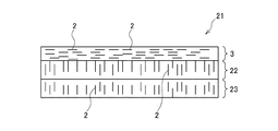
本発明の第1の実施形態に係る熱伝導性絶縁シートについて説明する。図1は本実施形態の熱伝導性絶縁シートの構成を模式的に示す図である。図1に示すように、本実施形態の熱伝導性絶縁シート1は、六方晶窒化ホウ素2が厚さ方向に配向している縦配向シート4の上に、六方晶窒化ホウ素2が幅方向又は長さ方向に配向している横配向シート3が積層された構成となっている。そして、この熱伝導性絶縁シート1は、横配向シート3が、発熱する部品側になるよう配置される。
(First embodiment)
The thermally conductive insulating sheet according to the first embodiment of the present invention will be described. FIG. 1 is a diagram schematically showing the configuration of the thermally conductive insulating sheet of the present embodiment. As shown in FIG. 1, the thermally conductive insulating sheet 1 of the present embodiment has a
[横配向シート3]
横配向シート3は、少なくとも、エポキシ樹脂と、硬化剤と、六方晶窒化ホウ素を有する樹脂組成物を硬化させて成形したものであり、その幅方向又は長さ方向に六方晶窒化ホウ素2が配向している。また、この横配向シート3を形成する樹脂組成物では、エポキシ樹脂及び硬化剤の少なくとも一方がナフタレン構造を有している。
[Horizontal orientation sheet 3]
The laterally oriented
(エポキシ樹脂)
本実施形態の熱伝導性絶縁シート1に使用されるエポキシ樹脂は、1分子中に2個以上のエポキシ基を有するエポキシ化合物であればよく、特に、分子中にナフタレン構造やアントラセン構造などの多環芳香族構造を有するものが好ましい。その中でも、ナフタレン構造は、常温で液状であり、六方晶窒化ホウ素2との濡れ性が良好であるため、分子中にナフタレン構造を有するエポキシ樹脂を使用することにより、六方晶窒化ホウ素2の充填率を高め、放熱性及び耐熱性を向上させることができる。
(Epoxy resin)
The epoxy resin used for the heat conductive insulating sheet 1 of the present embodiment may be an epoxy compound having two or more epoxy groups in one molecule, and in particular, there are many such as naphthalene structure and anthracene structure in the molecule. Those having a ring aromatic structure are preferred. Among them, the naphthalene structure is liquid at normal temperature and has good wettability with the
横配向シート3を形成する樹脂組成物に対するエポキシ樹脂の配合量は、特に限定するものではないが、得られる硬化体の特性、特に、絶縁性及び金属材との密着性の観点から、樹脂組成物全量あたり、7.5〜33.0質量%であることが好ましく、より好ましくは8.8〜31.7質量%である。
The compounding amount of the epoxy resin with respect to the resin composition forming the laterally oriented
(硬化剤)
本実施形態の熱伝導性絶縁シート1に使用される硬化剤は、前述したエポキシ樹脂の硬化剤であり、具体的には、フェノールノボラック樹脂、酸無水物樹脂、アミノ樹脂、イミダゾール類などを使用することができる。この硬化剤についても、多環芳香族構造を有するものが好ましく、特に、ナフタレン構造を有するものが好ましい。これにより、六方晶窒化ホウ素2の充填率を高め、放熱性及び耐熱性を向上させることができる。
(Curing agent)
The curing agent used in the thermally conductive insulating sheet 1 of the present embodiment is the epoxy resin curing agent described above, and specifically uses phenol novolac resin, acid anhydride resin, amino resin, imidazoles, and the like. can do. Also about this hardening | curing agent, what has a polycyclic aromatic structure is preferable, and what has a naphthalene structure is especially preferable. Thereby, the filling rate of the
横配向シート3を形成する樹脂組成物に対する硬化剤の配合量は、特に限定するものではないが、得られる硬化体の特性、特に絶縁性及び金属材との密着性の観点から、樹脂組成物全量あたり、0.5〜8.0質量%であることが好ましく、より好ましくは0.9〜6.55質量%である。特に、硬化剤がフェノールノボラック樹脂、酸無水物樹脂又はアミノ樹脂である場合は、エポキシ樹脂に対して当量比で0.75〜1.25であることが好ましく、より好ましくは当量比0.8〜1.2である。なお、イミダゾール類などのようにイオン重合により硬化するものについては、当量比は特に限定されない。
The blending amount of the curing agent with respect to the resin composition forming the laterally oriented
(六方晶窒化ホウ素2)
六方晶窒化ホウ素2は、黒鉛に似た燐片状結晶構造を有し、熱伝導性、耐熱性及び電気絶縁性に優れた平板状粒子である。このため、六方晶窒化ホウ素2を高充填することにより、放熱性に優れた熱伝導性絶縁シートが得られる。一方、六方晶窒化ホウ素2を高充填すると、成形性が低下するという問題点がある。そこで、本実施形態の熱伝導性絶縁シートでは、ナフタレン構造を有するエポキシ樹脂及び/又は硬化剤を使用することで、六方晶窒化ホウ素2の高充填化を実現している。
(Hexagonal boron nitride 2)
具体的には、横配向シート3における六方晶窒化ホウ素2の含有量は50〜85体積%である。六方晶窒化ホウ素2の含有量が50体積%未満の場合、熱伝導率が低下し、十分な放熱性能が得られない。また、六方晶窒化ホウ素2の含有量が85体積%を超えると、成形時に空隙が生じやすくなり、絶縁性や機械強度が低下する。なお、横配向シート3における六方晶窒化ホウ素2の含有量は、放熱性及び成形性の観点から、65〜83体積%であることが好ましい。
Specifically, the content of
また、六方晶窒化ホウ素2は、平均粒子径が10〜400μmの粗粉であることが望ましい。これにより、樹脂組成物の流動性を低下させることなく、高配向の配向シートを形成することができる。この場合、六方晶窒化ホウ素2のGI(Graphitization:黒鉛化指数)値は1.5以下であることが好ましい。
The
ここで、「GI値」とは、X線回折により測定した(002)回折線の面積[Area(002)]と、(100)回折線の面積[Area(100)]との比で表され、下記数式1により求められる値である。即ち、このGI値が低いものほど、結晶化が進んでいることになる。そして、結晶化度が低い六方晶窒化ホウ素は、粒子が十分に成長しておらず、熱伝導度が低いため、本実施形態の熱伝導性絶縁シート1では、GI値が1.5以下で、結晶化進んでいる六方晶窒化ホウ素を使用することが望ましい。 Here, the “GI value” is represented by a ratio of the area [Area (002)] of (002) diffraction lines measured by X-ray diffraction and the area [Area (100)] of (100) diffraction lines. , Which is a value obtained by the following mathematical formula 1. That is, the lower the GI value is, the more crystallization proceeds. The hexagonal boron nitride having a low degree of crystallinity does not have a sufficiently grown particle and has a low thermal conductivity. Therefore, in the thermally conductive insulating sheet 1 of the present embodiment, the GI value is 1.5 or less. It is desirable to use hexagonal boron nitride which has been crystallized.

更に、六方晶窒化ホウ素2は、タップ密度が0.5g/cm3以上であることが望ましい。これにより、配向シートにおける無機フィラーの充填率及び分散性を良好にすることができる。ここで、「タップ密度」とは、フィラーの嵩密度を表すもので、JIS Z 2500(2045)に規定されるように、振動させた容器内の粉末の単位体積当たりの質量である。
Furthermore, the
(無機フィラー)
更に、横配向シート3を形成する樹脂組成物には、前述した六方晶窒化ホウ素2と共に、平均粒子径が0.5〜4.0μmの無機フィラーの微粉が配合されていることが望ましい。六方晶窒化ホウ素2の粗粉と共に、無機フィラーの微粉を配合することにより、粗粉間に微粉が充填され、全体しての充填率を増加させることができる。
(Inorganic filler)
Furthermore, it is desirable that the resin composition forming the laterally oriented
この微粉の素材としては、例えば、酸化珪素、酸化アルミニウム、酸化マグネシウム、窒化ホウ素、窒化アルミニウム、窒化珪素、炭化窒素などが挙げられる。これらの中でも、特に、六方晶窒化ホウ素が好適であり、六方晶窒化ホウ素の微粉を配合することにより、低誘電率、高絶縁性、高熱伝導率の配向シートを得ることができる。また、球状アルミナを使用すると、高絶縁性で高熱伝導率の配向シートを得ることができる。 Examples of the fine powder material include silicon oxide, aluminum oxide, magnesium oxide, boron nitride, aluminum nitride, silicon nitride, and nitrogen carbide. Among these, hexagonal boron nitride is particularly suitable. By blending hexagonal boron nitride fine powder, an oriented sheet having low dielectric constant, high insulation, and high thermal conductivity can be obtained. Moreover, when spherical alumina is used, an oriented sheet having high insulation and high thermal conductivity can be obtained.
なお、六方晶窒化ホウ素2の粗粉と、無機フィラーの微粉とを併用する場合、これらの総量に対して、粗粉の配合比率を70質量%以上にすることが好ましく、75質量%以上にすることがより好ましい。これにより、空隙がなく、緻密に充填された配向性シートを形成することができる。
In addition, when using together the coarse powder of the
(その他の成分)
横配向シート3を形成する樹脂組成物には、前述した各成分に加えて、有機溶剤、カップリング剤及び界面活性剤などが配合されていてもよい。
(Other ingredients)
In addition to the components described above, an organic solvent, a coupling agent, a surfactant, and the like may be blended in the resin composition that forms the laterally oriented
(配向度)
横配向シート3は、下記数式2により求められる配向度(Orientation Index)がO.I<<1.0であることが好ましい。これにより、熱を広範囲に拡散させることができるため、伝熱面積が増加し、熱放散性能が更に向上する。また、BN粒子の遮蔽効果により、絶縁性も向上させることができる。
(Degree of orientation)
The laterally oriented
[縦配向シート4]
横配向シート4は、前述した横配向シート3と同様に、少なくとも、エポキシ樹脂と、硬化剤と、六方晶窒化ホウ素を有する樹脂組成物を硬化させて成形したものである。そして、その厚さ方向に、六方晶窒化ホウ素2が配向している。また、この縦配向シート4を形成する樹脂組成物でも、エポキシ樹脂及び硬化剤の少なくとも一方が、多環芳香族構造、特に、ナフタレン構造を有していることが望ましい。
[Vertical orientation sheet 4]
The laterally oriented
この縦配向シート4を形成する樹脂組成物の構成は、前述した横配向シート3と同様である。なお、横配向シート3と縦配向シート4とを組成が同じ樹脂組成物で形成してもよいが、組成が異なる樹脂組成物で形成することもできる。
The configuration of the resin composition forming the longitudinally oriented
(配向度)
縦配向シート4は、上記数式2により求められる配向度(Orientation Index)がO.I>0.5であることが好ましい。これにより、縦方向(厚さ方向)の伝熱性を高めることができるため、放熱効率が更に向上する。
(Degree of orientation)
The longitudinally oriented
[各シートの厚さ]
横配向シート3及び縦配向シート4の厚さは、特に限定するものではなく、用途に応じて適宜設定することができるが、縦配向シート4の厚さを、横配向シート3よりも厚くすることが望ましい。これにより、横方向シート3による熱を拡散させる効果と、縦配向シート4による熱をシート外、例えばヒートシンクや金属ベース材などに、効率よく伝達させる効果を、効率的にかつ相乗的に得ることができる。その結果、放熱性能を更に向上させることができる。
[Thickness of each sheet]
The thicknesses of the laterally oriented
なお、横配向シート3は、縦方向(厚さ方向)への熱伝達性能が低いため、放熱性向上の観点から、横配向シート3の厚さは20μm以下であることが好ましい。
In addition, since the
[製造方法]
次に、前述した構成の熱伝導性絶縁シート1の製造方法について、説明する。図2(a)〜(e)は本実施形態の熱伝導性絶縁シート1の製造方法の一例を、その工程順に示す模式図である。本実施形態の熱伝導性絶縁シート1は、六方晶窒化ホウ素2が幅方向又は長さ方向に配向している横配向シート3と、六方晶窒化ホウ素2が厚さ方向に配向している縦配向シート4とを個別に作製した後、積層することもできるが、1つの成形体から、横配向シート3及び縦配向シート4を切り出してもよい。
[Production method]
Next, the manufacturing method of the heat conductive insulating sheet 1 of the structure mentioned above is demonstrated. Drawing 2 (a)-(e) is a mimetic diagram showing an example of a manufacturing method of heat conductive insulating sheet 1 of this embodiment in the order of the process. The thermally conductive insulating sheet 1 of this embodiment includes a laterally oriented
その場合、横配向シート3及び縦配向シート4は、前述した樹脂組成物を用いて、押出成形やプレス成形などにより形成することができる。その際、積層前の横配向シート3a及び縦配向シート4aは、Bステージ状態であることが望ましい。ここで、「Bステージ状態」とは、樹脂組成物が室温で乾いた状態を示し、高温に加熱すると再び溶融する状態をいい、より厳密には、DSC(Differential Scanning Calorimetry:示差走査型熱量計)を用いて、硬化時に発生する熱量から計算した値で硬化度が70%未満の状態を示す。
In that case, the laterally oriented
そして、Bステージ状態の縦配向シート4a上に、Bステージ状態の横配向シート3aを配置し、例えば上下方向又は全周囲から加圧しながら加熱することにより、これらをCステージ状態にすることが望ましい。これにより、横配向シート3と縦配向シート4とを、容易に一体化することができる。ここで、「Cステージ状態」とは、樹脂組成物の硬化がほぼ終了した状態で、高温に加熱しても再度溶融することはない状態をいい、硬化度70%以上の状態をいう。
Then, it is desirable that the B-stage state
また、図2(a)〜(e)に示すように、押出成形装置10などにより成形して得た横配向シート3aを複数枚積層して成形体5とし、これを、破断刃11により、横配向シート3aの厚さ方向、即ち、六方晶窒化ホウ素2の配向方向に垂直な方向に切断することで、縦配向シート4aを形成してもよい。この場合、縦方向シート4aは、複数の角柱状配向体6が一方向に配列された構成となる。また、この図2に示す製造方法においても、積層前の横配向シート3a及び縦配向シート4aはBステージ状態で、積層後にCステージ状態とすることが望ましい。
Also, as shown in FIGS. 2 (a) to (e), a plurality of laterally oriented
本実施形態の熱伝導性絶縁シート1では、横配向シート3と縦配向シート4とが積層された構成であるため、横方向シート3において、電子部品などで発生した熱を横方向に拡散し、更に拡散した熱を、縦方向シート4によりシート外に逃がす。これにより、効率的に放熱することが可能となる。
The thermally conductive insulating sheet 1 of the present embodiment has a configuration in which the laterally oriented
なお、図1に示す熱伝導性絶縁シート1は、横配向シート3と縦配向シート4とが1枚ずつ積層された構成となっているが、本発明はこれに限定されるものではなく、横配向シート3及び/又は縦配向シート4とが、複数枚積層されていてもよい。図3は本実施形態の変形例に係る熱伝導性絶縁シートの構成を模式的に示す図である。なお、図3においては、図1に示す熱伝導性絶縁シート1の構成要素と同じものには、同じ符号を付し、その詳細な説明は省略する。
In addition, although the heat conductive insulating sheet 1 shown in FIG. 1 has a configuration in which the laterally oriented
図3に示すように、本変形例の熱伝導性絶縁シート21では、厚さが同一又は異なる2枚の縦配向シート22、23上に、横配向シート3が積層されている。このように、横配向シート及び/又は縦配向シートを複数枚積層することにより、横配向及び縦配向それぞれ単一のシート化プロセスで、シートの積層枚数や配向体の幅を変更することにより、任意のサイズ及び厚さの熱伝導性絶縁シートを得ることができる。なお、本変形例の熱伝導性絶縁シート21における上記以外の構成及び効果は、前述した第1の実施形態と同様である。
As shown in FIG. 3, in the heat conductive insulating
(第2の実施形態)
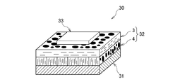
本発明の第2の実施形態に係る金属ベース基板について説明する。図4は本実施形態の金属ベース基板の構成を模式的に示す図である。なお、図4においては、図1に示す熱伝導性絶縁シート1の構成要素と同じものには、同じ符号を付し、その詳細な説明は省略する。図4に示すように、本実施形態の金属ベース基板30は、金属ベース材31上に、Cステージ状態の熱伝導性絶縁層32が形成されており、その上に導体箔33が積層されている。
(Second Embodiment)
A metal base substrate according to a second embodiment of the present invention will be described. FIG. 4 is a diagram schematically showing the configuration of the metal base substrate of the present embodiment. In FIG. 4, the same components as those of the thermally conductive insulating sheet 1 shown in FIG. 1 are denoted by the same reference numerals, and detailed description thereof is omitted. As shown in FIG. 4, the
[金属ベース材31]
金属ベース材31の材質は、特に限定されるものではないが、アルミニウム、鉄、銅、ステンレス又はこれらの合金が好ましく、特に、放熱性、価格、軽量性及び加工性の面でバランスが取れているという点で、アルミニウムが好ましい。また、金属ベース材31は、熱伝導性絶縁層32との密着性を向上させるため、熱伝導性絶縁層32との接着面に、アルマイト処理、脱脂処理、サンドブラスト、エッチング、各種メッキ処理、カップリング剤などを使用したプライマー処理などの各種表面処理が施されていることが望ましい。
[Metal base material 31]
The material of the
[熱伝導性絶縁層32]
熱伝導性絶縁層32は、前述した第1の実施形態又はその変形例の熱伝導性絶縁シートで構成されている。即ち、熱伝導性絶縁層32は、六方晶窒化ホウ素2が厚さ方向に配向している1又は2以上の縦配向シート4の上に、六方晶窒化ホウ素2が幅方向又は長さ方向に配向している1又は2以上の横配向シート3が積層された構成となっている。
[Thermal conductive insulating layer 32]
The heat conductive insulating
Cステージ状態の熱伝導性絶縁層32の厚さは、絶縁強度及び放熱特性の観点から、80〜300μmであることが好ましい。熱伝導性絶縁層32の厚さが80μm未満の場合、所望の絶縁強度を得ることが難しくなることがあり、また、絶縁接着層2bの厚さが300μmを超えると、熱抵抗が大きくなり、放熱特性が低下することがある。
The thickness of the thermally conductive insulating
一方、Cステージ状態の熱伝導性絶縁層32の絶縁強度は、30kV/mm以上であることが好ましく、より好ましくは35kV/mm以上である。これにより、より高品質で高放熱の金属ベース回路基板を実現することができる。
On the other hand, the insulation strength of the thermally conductive insulating
[導体箔33]
導体箔33には、例えば、アルミニウム、鉄、銅、ステンレス若しくはこれらの合金からなる箔材又はクラッド箔を使用することができ、特に、電気伝導度及び放熱性の観点から銅箔を使用することが好ましい。また、熱伝導性絶縁層32との密着性を向上させるために、熱伝導性絶縁層32との接着面に、脱脂処理、サンドブラスト、エッチング、各種メッキ処理、カップリング剤などを使用したプライマー処理などの各種表面処理が施されていることが望ましい。
[Conductor foil 33]
For the
[熱抵抗]
Cステージ状態の熱伝導性絶縁層32を含む金属ベース基板の熱抵抗は、1.0℃/W以下であることが好ましく、0.9℃/W以下であることがより好ましい。これにより、より高品質で高放熱の金属ベース回路基板を実現することができる。
[Thermal resistance]
The thermal resistance of the metal base substrate including the thermally conductive insulating
[製造方法]
次に、本実施形態の金属ベース基板30の製造方法について説明する。図5(a)〜(c)は本実施形態の金属ベース基板の製造方法の一例を、その工程順に示す模式図である。図5(a)に示すように、本実施形態の金属ベース基板30を製造する際は、先ず、金属ベース31上に縦配向シート4aを配置する。その際の縦配向性シート4aはBステージ状態であることが望ましい。また、縦配向シート4aは、図2(a)〜(d)に示す工程により製造された複数の角柱状配向体6が一方向に配列された構成のものでもよい。
[Production method]
Next, the manufacturing method of the
次に、図5(b)に示すように、縦配向シート4aの上に、六方晶窒化ホウ素2が幅方向又は長さ方向に配向している横配向シート3aを積層する。その際、横配向シート3aもBステージ状態であることが望ましい。
Next, as shown in FIG. 5B, a laterally oriented
次に、横配向シート3a上に導体箔33を積層し、加圧しながら加熱して、金属ベース基板30を得る。これにより、例えば横配向シート3a及び縦配向シート4aがBステージ状態である場合は、Cステージ状態の横配向シート3及び縦配向シート4からなる熱伝導性絶縁層32が形成される。
Next, the
以上詳述したように、本実施形態の金属ベース基板30では、熱伝導性絶縁層32が横配向シート3と縦配向シート4とが積層された構成となっており、半導体などの電子部品が搭載される側に横配向シート3が、放熱に寄与する金属ベース材31側に縦配向シート4がそれぞれ配置されている。この構成により、電子部品で発生した熱を横方向に拡散すると共に、拡散した熱を縦方向シート4により金属ベース材31に伝達することができるため、放熱効率が向上し、優れた放熱特性が得られる。また、横配向している粒子の遮蔽効果により、金属ベース基板30には、高い絶縁性能も付与することが可能となる。
As described in detail above, in the
(第3の実施形態)
本発明の第3の実施形態に係る金属ベース回路基板について説明する。本実施形態の回路基板は、前述した第2の実施形態の金属ベース基板30の導体箔33を加工して、熱伝導性絶縁層32上に所定の導体回路を形成したものである。
(Third embodiment)
A metal base circuit board according to a third embodiment of the present invention will be described. The circuit board of this embodiment is obtained by processing the
本実施形態の金属ベース回路基板における導体回路の形成方法は、特に限定されるものではなく、公知の方法を適用することができる。例えば、スクリーン印刷法又は写真現像法により、金属ベース基板30の導体箔33上にエッチングレジストを形成し、導体箔33の表面の所定位置をマスクする。その状態で、導体箔33の一部を、塩化第二鉄エッチング液、塩化第二銅エッチング液、過酸化水素/硫酸エッチング液、アルカリエッチング液等で腐食溶解した後、エッチングレジストを剥離する。これにより、熱伝導性絶縁層32に導体回路が形成される。
The formation method of the conductor circuit in the metal base circuit board of this embodiment is not specifically limited, A well-known method is applicable. For example, an etching resist is formed on the
本実施形態の金属ベース回路基板では、横配向シート3上に導体回路が形成されているため、パワー半導体などのように発熱量が大きい電子部品が搭載された場合でも、その熱を横方向に拡散することができる。そして、横方向に拡散した熱は、縦方向シート4を介して金属ベース材31に伝達されるため、放熱効率が向上し、優れた放熱特性が得られる。
In the metal base circuit board of the present embodiment, since the conductor circuit is formed on the laterally oriented
以下、本発明の実施例及び比較例を挙げて、本発明の効果について具体的に説明する。本実施例においては、下記表1に示す構成の熱伝導性絶縁シートを作製し、その特性を評価した。 Hereinafter, the effects of the present invention will be specifically described with reference to Examples and Comparative Examples of the present invention. In this example, a heat conductive insulating sheet having a configuration shown in Table 1 below was produced and its characteristics were evaluated.
<熱伝導性絶縁シートの製造方法>
下記表1,2に示す組成の樹脂組成物により、横配向樹脂シート及び縦配向樹脂シートを作製し、積層した。その際、エポキシ樹脂には、ナフタレン構造を含有するナフタレン型エポキシ樹脂(DIC社製、HP4032)、硬化剤にはイミダゾール類(四国化成社製、2E4MZ−CN)を使用した。また、カップリング剤には、シランカップリング剤(東レダウコーニング社製、Z−0640N)を使用した。更に、無機フィラーの微粉は、球状の酸化アルミニウム(電気化学工業社製、ASFP−20)を使用した。この酸化アルミニウムは、粒子径が3.0μm以下のものを90体積%含有し、平均粒子径は0.5μmであった。
<The manufacturing method of a heat conductive insulating sheet>
A laterally oriented resin sheet and a longitudinally oriented resin sheet were prepared and laminated using the resin compositions having the compositions shown in Tables 1 and 2 below. At that time, a naphthalene type epoxy resin (manufactured by DIC, HP4032) containing a naphthalene structure was used as the epoxy resin, and an imidazole (manufactured by Shikoku Kasei Co., Ltd., 2E4MZ-CN) was used as the curing agent. Moreover, the silane coupling agent (the Toray Dow Corning company make, Z-0640N) was used for the coupling agent. Further, spherical aluminum oxide (ASFP-20, manufactured by Denki Kagaku Kogyo Co., Ltd.) was used as the fine powder of the inorganic filler. This aluminum oxide contained 90% by volume of particles having a particle size of 3.0 μm or less, and the average particle size was 0.5 μm.
なお、下記表1,2における「BN」は、六方晶窒化ホウ素である。また、下記表1,2に示す六方晶窒化ホウ素(BN)及び無機フィラー微粉の平均粒子径は、島津製作所製「レーザー回折式粒度分布測定装置SALD−200」を用いて測定した。具体的には、先ず、ガラスビーカーに、純水:50ccと六方晶窒化ホウ素:5gとを投入し、スパチュラを用いて撹拌した後、超音波洗浄機で10分間、分散処理を行った。 In Tables 1 and 2 below, “BN” is hexagonal boron nitride. The average particle diameters of hexagonal boron nitride (BN) and inorganic filler fine powder shown in Tables 1 and 2 below were measured using “Laser Diffraction Particle Size Analyzer SALD-200” manufactured by Shimadzu Corporation. Specifically, first, pure water: 50 cc and hexagonal boron nitride: 5 g were put into a glass beaker, stirred with a spatula, and then subjected to dispersion treatment for 10 minutes with an ultrasonic cleaner.
次に、分散処理した六方晶窒化ホウ素の溶液を、スポイトを用いて、装置のサンプラ部に一滴ずつ添加し、吸光度が安定した時点で測定を行った。レーザー回折式粒度分布測定装置では、センサで検出した粒子による回折/散乱光の光強度分布のデータから粒度分布を計算した。平均粒子径は測定される粒子径の値に相対粒子量(差分%)を乗じて、相対粒子量の合計(100%)で割って求めた。平均粒子径は粒子の平均直径である。 Next, the dispersion-treated hexagonal boron nitride solution was added drop by drop to the sampler portion of the apparatus using a dropper, and measurement was performed when the absorbance was stabilized. In the laser diffraction particle size distribution analyzer, the particle size distribution is calculated from the data of the light intensity distribution of the diffracted / scattered light by the particles detected by the sensor. The average particle size was determined by multiplying the value of the measured particle size by the relative particle amount (difference%) and dividing by the total relative particle amount (100%). The average particle diameter is the average diameter of the particles.
また、実施例及び比較例の各熱伝導性絶縁シートは、下記表1に示す樹脂組成物を、押出成型装置を用いて1.0mm厚の薄板状に成形し、更に、10.0kgf/cm2(0.98MPa)の圧力で上下面間を押し付けた状態で、100℃で5分間の加熱により半硬化させて、Bステージ状態の横配向シート3aを得た。また、この押出成型後の板状体を50枚積層し、50.0kgf/cm2(4.90MPa)の圧力で上下横両面間を等方向的に押し付けた状態で、100℃で10分間の加熱により半硬化させた後、厚さ方向に切断してBステージ状態の縦配向シート4aを得た。
Moreover, each heat conductive insulating sheet of an Example and a comparative example shape | molds the resin composition shown in following Table 1 in the thin plate shape of 1.0 mm thickness using an extrusion molding apparatus, Furthermore, 10.0 kgf / cm In a state where the upper and lower surfaces were pressed with a pressure of 2 (0.98 MPa), it was semi-cured by heating at 100 ° C. for 5 minutes to obtain a B-staged horizontally oriented
そして、縦配向シート4a上に横配向シート3aを積層した後、1.0kgf/cm2(98.1kPa)の圧力で上下両面を押し付けた状態で、150℃の温度条件下で120分間加熱して硬化させ、Cステージ状態の熱伝導性絶縁シート1を得た。
And after laminating the
<放熱特性>
前述した方法によって作製した実施例及び比較例の熱伝導性絶縁シートを、厚さ1.5mmのアルミニウム板上に積層した後加熱して半硬化状態としたものに、更に、35mm厚の銅箔を貼り合わせた後、完全に硬化させて、金属ベース基板を作製した。次に、各基板を、縦3cm、横4cmの大きさに切り出すと共に、その銅箔を、15mm角を残して、その他の部分をエッチングにより除去して、放熱特性評価用試料とした。
<Heat dissipation characteristics>
The heat conductive insulating sheets of Examples and Comparative Examples prepared by the above-described method were laminated on an aluminum plate having a thickness of 1.5 mm and then heated to a semi-cured state. Were bonded together and completely cured to produce a metal base substrate. Next, each substrate was cut out to a size of 3 cm in length and 4 cm in width, and the copper foil was removed by etching except for a 15 mm square to obtain a sample for evaluating heat dissipation characteristics.
評価の際、各試料は、銅箔上にTO−220型トランジスターを半田付けした後、15℃に温調された放熱フィン上に、放熱グリースを介して固定した。そして、各試料に搭載されたトランジスターに通電して発熱(熱流W=20W)させ、トランジスターの表面温度(Tj)と放熱フィン上の温度(Ti=15℃)との差を測定した。 In the evaluation, each sample was soldered with a TO-220 type transistor on a copper foil, and then fixed on a heat radiation fin whose temperature was controlled at 15 ° C. via heat radiation grease. Then, the transistor mounted on each sample was energized to generate heat (heat flow W = 20 W), and the difference between the surface temperature (Tj) of the transistor and the temperature on the radiation fin (Ti = 15 ° C.) was measured.
その測定結果に基づき、下記数式3により、試験片の熱抵抗(A)を求めた。なお、トランジスターの表面温度(Tj)及び絶縁層(熱伝導性絶縁シート)の表面温度は、赤外線サーモグラフィ(NEC Avio赤外線テクノロジ株式会社製 H2640)を用いて測定した。
Based on the measurement result, the thermal resistance (A) of the test piece was obtained by the following
<絶縁強度>
前述した方法によって作製した実施例及び比較例の熱伝導性絶縁シートを、厚さ1.5mmのアルミニウム板上に積層したものに、厚さ0.1mmの銅箔を積層した後、150℃で2.0時間加熱して、熱伝導性絶縁シートを完全に硬化させて、絶縁強度評価用基板を作製した。
<Insulation strength>
After laminating the copper foil having a thickness of 0.1 mm on the aluminum conductive sheet having the thickness of 1.5 mm laminated on the heat conductive insulating sheet of the example and the comparative example prepared by the method described above, at 150 ° C. By heating for 2.0 hours, the thermally conductive insulating sheet was completely cured to produce a substrate for evaluating the insulation strength.
次に、この評価用基板の銅箔を、直径20mmの円形部分を残してエッチングしたものを、絶縁油中に浸漬し、室温下で、銅箔とアルミニウム板間に交流電圧を印加し、JIS C2110に基づいて、初期耐電圧を測定した。その際、測定器には、菊水電気工業株式会社製 TOS−8700を用いた。なお、初期耐電圧は、20kV/mm以上が必要である。 Next, the copper foil of this evaluation board, which was etched leaving a circular portion with a diameter of 20 mm, was immersed in insulating oil, and an AC voltage was applied between the copper foil and the aluminum plate at room temperature, and JIS The initial withstand voltage was measured based on C2110. At that time, TOS-8700 manufactured by Kikusui Electric Co., Ltd. was used as a measuring instrument. The initial withstand voltage is required to be 20 kV / mm or more.
<引き剥がし強さ>
前述した放熱特性評価用基板の銅箔を、幅10mmの帯状に残し、その他の部分はエッチングにより除去して、引き剥がし強さ測定用試料とした。そして、東洋ボールドウィン株式会社(株式会社オリエンテック)製 テンシロン試験機 U−1160を用いて、銅箔と基板の角度を90°、引張速度を50mm/分とし、それ以外の条件はJIS C6481に基づいて、試料を剥離したときの荷重を測定した。
<Stripping strength>
The copper foil of the substrate for evaluating heat radiation characteristics described above was left in a strip shape having a width of 10 mm, and the other portions were removed by etching to obtain a peel strength measurement sample. Then, using a Tensilon tester U-1160 manufactured by Toyo Baldwin Co., Ltd. (Orientec Co., Ltd.), the angle between the copper foil and the substrate was 90 °, the tensile speed was 50 mm / min, and other conditions were based on JIS C6481. Then, the load when the sample was peeled was measured.
以上の結果を、下記表1,2にまとめて示す。なお、下記表1,2に示す「判定」は、熱抵抗が0.9℃/W以下、絶縁強度が35kV/mm以下、引き剥がし強さが5.0N/cm以上のものを○、それ以外を×とした。 The above results are summarized in Tables 1 and 2 below. In addition, “determination” shown in Tables 1 and 2 below indicates that the thermal resistance is 0.9 ° C./W or less, the insulation strength is 35 kV / mm or less, and the peel strength is 5.0 N / cm or more. Except for x.
上記表2に示すように、横配向シートのみで構成された比較例2,3のシートは、放熱特性や絶縁特性に劣っていた。また、横配向シートと縦配向シートの厚さが同であった比較例1のシートも、放熱特性が劣っていた。 As shown in Table 2 above, the sheets of Comparative Examples 2 and 3 composed only of the laterally oriented sheet were inferior in heat dissipation characteristics and insulation characteristics. Moreover, the sheet | seat of the comparative example 1 whose thickness of the horizontal orientation sheet | seat and the longitudinal orientation sheet | seat was the same was also inferior in the thermal radiation characteristic.
これに対して、本発明の範囲内で作製した実施例1〜7のシートは、放熱特性及び絶縁特性の両方が優れていた。これにより、本発明によれば、放熱特性に優れた熱伝導性絶縁シート、金属ベース基板及び回路基板が実現できることが確認された。 On the other hand, the sheet | seat of Examples 1-7 produced within the scope of the present invention was excellent in both heat dissipation characteristics and insulation characteristics. Thereby, according to this invention, it was confirmed that the heat conductive insulating sheet, metal base board | substrate, and circuit board which were excellent in the thermal radiation characteristic are realizable.
1、21 熱伝導性絶縁シート
2 無機フィラー
3 Cステージ状態の横配向シート
3a Bステージ状態の横配向シート
4、22、23 Cステージ状態の縦配向シート
4a Bステージ状態の縦配向シート
5 積層体
6 角柱状配向体
10 押出成型機
11 切断刃
30 金属ベース基板
31 金属ベース材
32 熱伝導性絶縁層
33 導体箔
DESCRIPTION OF
Claims (8)
前記縦配向シートの総厚が、前記横配向シートの総厚よりも厚い熱伝導性絶縁シート。 One or a plurality of longitudinally oriented sheets in which hexagonal boron nitride is oriented in the thickness direction, and laminated on the longitudinally oriented sheet, the hexagonal boron nitride is oriented in the width direction or the length direction. An orientation sheet,
A thermally conductive insulating sheet in which the total thickness of the longitudinally oriented sheet is thicker than the total thickness of the laterally oriented sheet.
前記絶縁層が請求項1乃至6のいずれか1項に記載の熱伝導性絶縁シートであり、前記導体層は前記横配向シート上に形成されている金属ベース基板。 A metal base substrate in which an insulating layer and a conductor layer are laminated in this order on a metal base material,
The metal base substrate in which the said insulating layer is a heat conductive insulating sheet of any one of Claims 1 thru | or 6, and the said conductor layer is formed on the said horizontal orientation sheet | seat.
前記絶縁層が請求項1乃至6のいずれか1項に記載の熱伝導性絶縁シートであり、前記導体回路は前記横配向シート上に形成されている回路基板。 A metal base circuit board in which an insulating layer is formed on a metal base material, and a conductor circuit is formed on the insulating layer,
The circuit board in which the insulating layer is the thermally conductive insulating sheet according to any one of claims 1 to 6, and the conductor circuit is formed on the laterally oriented sheet.
Priority Applications (1)
| Application Number | Priority Date | Filing Date | Title |
|---|---|---|---|
| JP2011123971A JP2012253167A (en) | 2011-06-02 | 2011-06-02 | Thermally conductive insulation sheet, metal base substrate and circuit board |
Applications Claiming Priority (1)
| Application Number | Priority Date | Filing Date | Title |
|---|---|---|---|
| JP2011123971A JP2012253167A (en) | 2011-06-02 | 2011-06-02 | Thermally conductive insulation sheet, metal base substrate and circuit board |
Publications (1)
| Publication Number | Publication Date |
|---|---|
| JP2012253167A true JP2012253167A (en) | 2012-12-20 |
Family
ID=47525719
Family Applications (1)
| Application Number | Title | Priority Date | Filing Date |
|---|---|---|---|
| JP2011123971A Pending JP2012253167A (en) | 2011-06-02 | 2011-06-02 | Thermally conductive insulation sheet, metal base substrate and circuit board |
Country Status (1)
| Country | Link |
|---|---|
| JP (1) | JP2012253167A (en) |
Cited By (13)
| Publication number | Priority date | Publication date | Assignee | Title |
|---|---|---|---|---|
| KR101418706B1 (en) | 2012-07-10 | 2014-07-10 | 히타치 긴조쿠 가부시키가이샤 | Chassis and method for producing chassis |
| JP2014148094A (en) * | 2013-02-01 | 2014-08-21 | Sumitomo Bakelite Co Ltd | Thermal conductive sheet and production method of thermal conductive sheet |
| JP2015220300A (en) * | 2014-05-16 | 2015-12-07 | パナソニックIpマネジメント株式会社 | Thermal conductor |
| KR20160120481A (en) * | 2015-04-08 | 2016-10-18 | 삼성전기주식회사 | Circuit board |
| KR20160120486A (en) * | 2015-04-08 | 2016-10-18 | 삼성전기주식회사 | Circuit board and method of manufacturing the same |
| KR20160126290A (en) * | 2015-04-23 | 2016-11-02 | 삼성전기주식회사 | Printed circuit board, semiconductor package and method of manufacturing the same |
| US9558311B2 (en) | 2013-10-31 | 2017-01-31 | International Business Machines Corporation | Surface region selection for heat sink placement |
| JP2018022767A (en) * | 2016-08-03 | 2018-02-08 | 三菱瓦斯化学株式会社 | Method for producing heat conductive sheet |
| JP2019114755A (en) * | 2017-12-26 | 2019-07-11 | 京セラ株式会社 | Heat sink and electronic apparatus using the same |
| WO2019160004A1 (en) * | 2018-02-14 | 2019-08-22 | 積水ポリマテック株式会社 | Heat-conductive sheet |
| JP2021104672A (en) * | 2018-04-17 | 2021-07-26 | 積水化学工業株式会社 | Insulation sheet, laminate and substrate |
| CN114421143A (en) * | 2021-12-30 | 2022-04-29 | 哈尔滨工业大学(深圳) | Flexible antenna sensor and preparation method thereof |
| JP7446138B2 (en) | 2020-03-27 | 2024-03-08 | 株式会社ノリタケカンパニーリミテド | Ceramic sheet, method for manufacturing ceramic sheet, and green sheet |
Citations (7)
| Publication number | Priority date | Publication date | Assignee | Title |
|---|---|---|---|---|
| JPH01102988A (en) * | 1987-10-16 | 1989-04-20 | Tokyo Electric Co Ltd | Metal substrate for circuit |
| JPH05174623A (en) * | 1991-12-20 | 1993-07-13 | Matsushita Electric Works Ltd | Insulating sheet, metal wiring board using the same and manufacture therefor |
| JP2003060134A (en) * | 2001-08-17 | 2003-02-28 | Polymatech Co Ltd | Heat conductive sheet |
| JP2009094110A (en) * | 2007-10-03 | 2009-04-30 | Denki Kagaku Kogyo Kk | Heat dissipation member, its sheet, and its production method |
| JP2010044998A (en) * | 2008-08-18 | 2010-02-25 | Sekisui Chem Co Ltd | Insulating sheet, and laminated structural body |
| JP2010253730A (en) * | 2009-04-22 | 2010-11-11 | Sumitomo Electric Ind Ltd | Heat dissipation material, printed board, and method for manufacturing printed board |
| JP2011012193A (en) * | 2009-07-03 | 2011-01-20 | Denki Kagaku Kogyo Kk | Resin composition and use thereof |
-
2011
- 2011-06-02 JP JP2011123971A patent/JP2012253167A/en active Pending
Patent Citations (7)
| Publication number | Priority date | Publication date | Assignee | Title |
|---|---|---|---|---|
| JPH01102988A (en) * | 1987-10-16 | 1989-04-20 | Tokyo Electric Co Ltd | Metal substrate for circuit |
| JPH05174623A (en) * | 1991-12-20 | 1993-07-13 | Matsushita Electric Works Ltd | Insulating sheet, metal wiring board using the same and manufacture therefor |
| JP2003060134A (en) * | 2001-08-17 | 2003-02-28 | Polymatech Co Ltd | Heat conductive sheet |
| JP2009094110A (en) * | 2007-10-03 | 2009-04-30 | Denki Kagaku Kogyo Kk | Heat dissipation member, its sheet, and its production method |
| JP2010044998A (en) * | 2008-08-18 | 2010-02-25 | Sekisui Chem Co Ltd | Insulating sheet, and laminated structural body |
| JP2010253730A (en) * | 2009-04-22 | 2010-11-11 | Sumitomo Electric Ind Ltd | Heat dissipation material, printed board, and method for manufacturing printed board |
| JP2011012193A (en) * | 2009-07-03 | 2011-01-20 | Denki Kagaku Kogyo Kk | Resin composition and use thereof |
Cited By (21)
| Publication number | Priority date | Publication date | Assignee | Title |
|---|---|---|---|---|
| KR101418706B1 (en) | 2012-07-10 | 2014-07-10 | 히타치 긴조쿠 가부시키가이샤 | Chassis and method for producing chassis |
| JP2014148094A (en) * | 2013-02-01 | 2014-08-21 | Sumitomo Bakelite Co Ltd | Thermal conductive sheet and production method of thermal conductive sheet |
| US9558311B2 (en) | 2013-10-31 | 2017-01-31 | International Business Machines Corporation | Surface region selection for heat sink placement |
| JP2015220300A (en) * | 2014-05-16 | 2015-12-07 | パナソニックIpマネジメント株式会社 | Thermal conductor |
| KR102411997B1 (en) | 2015-04-08 | 2022-06-22 | 삼성전기주식회사 | Circuit board and method of manufacturing the same |
| KR20160120481A (en) * | 2015-04-08 | 2016-10-18 | 삼성전기주식회사 | Circuit board |
| KR20160120486A (en) * | 2015-04-08 | 2016-10-18 | 삼성전기주식회사 | Circuit board and method of manufacturing the same |
| JP2016201532A (en) * | 2015-04-08 | 2016-12-01 | サムソン エレクトロ−メカニックス カンパニーリミテッド. | Circuit board |
| KR102411999B1 (en) * | 2015-04-08 | 2022-06-22 | 삼성전기주식회사 | Circuit board |
| KR20160126290A (en) * | 2015-04-23 | 2016-11-02 | 삼성전기주식회사 | Printed circuit board, semiconductor package and method of manufacturing the same |
| KR102472945B1 (en) | 2015-04-23 | 2022-12-01 | 삼성전기주식회사 | Printed circuit board, semiconductor package and method of manufacturing the same |
| JP2018022767A (en) * | 2016-08-03 | 2018-02-08 | 三菱瓦斯化学株式会社 | Method for producing heat conductive sheet |
| JP7025204B2 (en) | 2017-12-26 | 2022-02-24 | 京セラ株式会社 | Heat sink and electronic device using it |
| JP2019114755A (en) * | 2017-12-26 | 2019-07-11 | 京セラ株式会社 | Heat sink and electronic apparatus using the same |
| WO2019160004A1 (en) * | 2018-02-14 | 2019-08-22 | 積水ポリマテック株式会社 | Heat-conductive sheet |
| JPWO2019160004A1 (en) * | 2018-02-14 | 2021-02-18 | 積水ポリマテック株式会社 | Thermal conductivity sheet |
| JP7221487B2 (en) | 2018-02-14 | 2023-02-14 | 積水ポリマテック株式会社 | thermally conductive sheet |
| US11610829B2 (en) | 2018-02-14 | 2023-03-21 | Sekisui Polymatech Co., Ltd. | Heat-conductive sheet |
| JP2021104672A (en) * | 2018-04-17 | 2021-07-26 | 積水化学工業株式会社 | Insulation sheet, laminate and substrate |
| JP7446138B2 (en) | 2020-03-27 | 2024-03-08 | 株式会社ノリタケカンパニーリミテド | Ceramic sheet, method for manufacturing ceramic sheet, and green sheet |
| CN114421143A (en) * | 2021-12-30 | 2022-04-29 | 哈尔滨工业大学(深圳) | Flexible antenna sensor and preparation method thereof |
Similar Documents
| Publication | Publication Date | Title |
|---|---|---|
| JP6023474B2 (en) | Thermally conductive insulating sheet, metal base substrate and circuit board, and manufacturing method thereof | |
| JP2012253167A (en) | Thermally conductive insulation sheet, metal base substrate and circuit board | |
| JP6313766B2 (en) | Boron nitride-resin composite circuit board, boron nitride-resin composite heat sink integrated circuit board | |
| WO2018181606A1 (en) | Heat-conducting member and heat-dissipating structure including said heat-conducting member | |
| JP2011012193A (en) | Resin composition and use thereof | |
| JP4893415B2 (en) | Heat dissipation film | |
| JP7271176B2 (en) | RESIN MATERIAL, RESIN MATERIAL MANUFACTURING METHOD AND LAMINATED PRODUCT | |
| TWI763868B (en) | Heat-dissipating sheet, method for producing heat-dissipating sheet, and laminate | |
| WO2012026012A1 (en) | Resin composition, molded object and substrate material both obtained from the resin composition, and circuit board including the substrate material | |
| KR101612596B1 (en) | Laminate and method for producing component for power semiconductor modules | |
| US20200216659A1 (en) | Resin material, method for producing resin material, and laminate | |
| JP7352173B2 (en) | Compositions, cured products, multilayer sheets, heat dissipation parts, and electronic parts | |
| JP2013098217A (en) | Method for manufacturing component for power semiconductor module | |
| TWI759481B (en) | Insulating sheet and laminate | |
| WO2019112048A1 (en) | Laminate and electronic device | |
| TWI772418B (en) | Insulating sheet and laminate | |
| KR102524427B1 (en) | Insulation Sheets and Laminates | |
| WO2022255450A1 (en) | Resin sheet, laminate, and semiconductor device | |
| JP2023107225A (en) | Laminate and semiconductor device | |
| JP2022088777A (en) | Thermally conductive resin composition, thermally conductive sheet, and metal-based substrate |
Legal Events
| Date | Code | Title | Description |
|---|---|---|---|
| A621 | Written request for application examination |
Free format text: JAPANESE INTERMEDIATE CODE: A621 Effective date: 20140424 |
|
| A131 | Notification of reasons for refusal |
Free format text: JAPANESE INTERMEDIATE CODE: A131 Effective date: 20141111 |
|
| A521 | Written amendment |
Free format text: JAPANESE INTERMEDIATE CODE: A523 Effective date: 20150107 |
|
| A131 | Notification of reasons for refusal |
Free format text: JAPANESE INTERMEDIATE CODE: A131 Effective date: 20150512 |
|
| A521 | Written amendment |
Free format text: JAPANESE INTERMEDIATE CODE: A523 Effective date: 20150707 |
|
| A02 | Decision of refusal |
Free format text: JAPANESE INTERMEDIATE CODE: A02 Effective date: 20150811 |