JP2012249928A - Ultrasonic diagnosis apparatus and ultrasonic image forming method - Google Patents
Ultrasonic diagnosis apparatus and ultrasonic image forming method Download PDFInfo
- Publication number
- JP2012249928A JP2012249928A JP2011126190A JP2011126190A JP2012249928A JP 2012249928 A JP2012249928 A JP 2012249928A JP 2011126190 A JP2011126190 A JP 2011126190A JP 2011126190 A JP2011126190 A JP 2011126190A JP 2012249928 A JP2012249928 A JP 2012249928A
- Authority
- JP
- Japan
- Prior art keywords
- ultrasonic
- measurement depth
- reception
- reception signal
- measurement
- Prior art date
- Legal status (The legal status is an assumption and is not a legal conclusion. Google has not performed a legal analysis and makes no representation as to the accuracy of the status listed.)
- Granted
Links
Images


Classifications
-
- G—PHYSICS
- G01—MEASURING; TESTING
- G01S—RADIO DIRECTION-FINDING; RADIO NAVIGATION; DETERMINING DISTANCE OR VELOCITY BY USE OF RADIO WAVES; LOCATING OR PRESENCE-DETECTING BY USE OF THE REFLECTION OR RERADIATION OF RADIO WAVES; ANALOGOUS ARRANGEMENTS USING OTHER WAVES
- G01S7/00—Details of systems according to groups G01S13/00, G01S15/00, G01S17/00
- G01S7/52—Details of systems according to groups G01S13/00, G01S15/00, G01S17/00 of systems according to group G01S15/00
- G01S7/52017—Details of systems according to groups G01S13/00, G01S15/00, G01S17/00 of systems according to group G01S15/00 particularly adapted to short-range imaging
- G01S7/52023—Details of receivers
- G01S7/52025—Details of receivers for pulse systems
- G01S7/52026—Extracting wanted echo signals
-
- G—PHYSICS
- G01—MEASURING; TESTING
- G01S—RADIO DIRECTION-FINDING; RADIO NAVIGATION; DETERMINING DISTANCE OR VELOCITY BY USE OF RADIO WAVES; LOCATING OR PRESENCE-DETECTING BY USE OF THE REFLECTION OR RERADIATION OF RADIO WAVES; ANALOGOUS ARRANGEMENTS USING OTHER WAVES
- G01S7/00—Details of systems according to groups G01S13/00, G01S15/00, G01S17/00
- G01S7/52—Details of systems according to groups G01S13/00, G01S15/00, G01S17/00 of systems according to group G01S15/00
- G01S7/52017—Details of systems according to groups G01S13/00, G01S15/00, G01S17/00 of systems according to group G01S15/00 particularly adapted to short-range imaging
- G01S7/52023—Details of receivers
- G01S7/52034—Data rate converters
-
- A—HUMAN NECESSITIES
- A61—MEDICAL OR VETERINARY SCIENCE; HYGIENE
- A61B—DIAGNOSIS; SURGERY; IDENTIFICATION
- A61B8/00—Diagnosis using ultrasonic, sonic or infrasonic waves
- A61B8/52—Devices using data or image processing specially adapted for diagnosis using ultrasonic, sonic or infrasonic waves
- A61B8/5207—Devices using data or image processing specially adapted for diagnosis using ultrasonic, sonic or infrasonic waves involving processing of raw data to produce diagnostic data, e.g. for generating an image
-
- G—PHYSICS
- G01—MEASURING; TESTING
- G01S—RADIO DIRECTION-FINDING; RADIO NAVIGATION; DETERMINING DISTANCE OR VELOCITY BY USE OF RADIO WAVES; LOCATING OR PRESENCE-DETECTING BY USE OF THE REFLECTION OR RERADIATION OF RADIO WAVES; ANALOGOUS ARRANGEMENTS USING OTHER WAVES
- G01S7/00—Details of systems according to groups G01S13/00, G01S15/00, G01S17/00
- G01S7/003—Transmission of data between radar, sonar or lidar systems and remote stations
Abstract
Description
この発明は、超音波診断装置および超音波画像生成方法に係り、特に、被検体による超音波エコーを受信したアレイトランスデューサから出力される受信信号を受信信号処理部で処理することで得られる受信データに基づいて超音波画像を生成する超音波診断装置に関する。 The present invention relates to an ultrasonic diagnostic apparatus and an ultrasonic image generation method, and in particular, received data obtained by processing a reception signal output from an array transducer that has received an ultrasonic echo from a subject with a reception signal processing unit. The present invention relates to an ultrasonic diagnostic apparatus that generates an ultrasonic image based on the above.
従来から、医療分野において、超音波画像を利用した超音波診断装置が実用化されている。一般に、この種の超音波診断装置は、超音波プローブのアレイトランスデューサから被検体内に向けて超音波ビームを送信し、被検体からの超音波エコーをアレイトランスデューサで受信して、その受信信号を装置本体で電気的に処理することにより超音波画像が生成される。 Conventionally, in the medical field, an ultrasonic diagnostic apparatus using an ultrasonic image has been put into practical use. In general, this type of ultrasonic diagnostic apparatus transmits an ultrasonic beam from an array transducer of an ultrasonic probe into a subject, receives an ultrasonic echo from the subject with the array transducer, and receives the received signal. An ultrasonic image is generated by electrical processing in the apparatus main body.
例えば、特許文献1には、超音波エコーを受信したアレイトランスデューサから出力された受信信号が、それぞれ、プリアンプで増幅され、A/DコンバータでA/D変換されてデジタルの受信データとされた後、適切な遅延を与えられることで互いに位相が合致した状態で加算され、これにより受信フォーカス処理を行う超音波診断装置が開示されている。
この受信フォーカス処理によって超音波エコーの焦点が絞り込まれた音線信号が生成され、このようにして生成された診断領域内の複数の音線信号に基づいて、被検体内の断層画像情報であるBモード画像信号が生成される。
For example,
A sound ray signal in which the focus of the ultrasonic echo is narrowed down by this reception focus processing is generated, and the tomographic image information in the subject is generated based on the plurality of sound ray signals in the diagnostic region thus generated. A B-mode image signal is generated.
このような超音波診断においては、超音波ビームが被検体内を進行するに従って減衰するので、深度が深くなるほど到達する超音波ビームの強度は小さくなる。また、被検体内の各部で反射されて超音波プローブに戻ってくる超音波エコーも、同様に進行するに従って減衰する。その結果、アレイトランスデューサから出力される受信信号の振幅は、測定深度に応じて変化することとなる。 In such an ultrasound diagnosis, since the ultrasound beam attenuates as it travels through the subject, the intensity of the reaching ultrasound beam decreases as the depth increases. In addition, the ultrasonic echoes reflected by the respective parts in the subject and returning to the ultrasonic probe are also attenuated as they proceed in the same manner. As a result, the amplitude of the reception signal output from the array transducer changes according to the measurement depth.
そこで、測定領域内の深度の浅い領域に対応する比較的大きな振幅の受信信号から深度の深い領域に対応する比較的小さな振幅の受信信号まで全域にわたる受信信号を良好な分解能でA/D変換するために、A/Dコンバータは大きなダイナミックレンジを有することが望まれるが、現存の超音波診断装置用のA/Dコンバータのダイナミックレンジは十分なものではなく、通常、プリアンプに可変利得アンプを組み合わせて、静的なプリアンプの利得の変更と、可変利得アンプにおける動的な利得の変化によって、ダイナミックレンジの不足分を補っている。 Therefore, A / D conversion is performed on the received signal over a wide range from a relatively large amplitude received signal corresponding to a shallow region in the measurement region to a relatively small amplitude received signal corresponding to a deep region with a good resolution. Therefore, it is desired that the A / D converter has a large dynamic range, but the dynamic range of the existing A / D converter for an ultrasonic diagnostic apparatus is not sufficient, and a variable gain amplifier is usually combined with a preamplifier. Thus, the shortage of the dynamic range is compensated by the change of the gain of the static preamplifier and the change of the dynamic gain of the variable gain amplifier.
しかしながら、プリアンプの利得を大きくし過ぎると、深度の浅い領域では、過大の受信信号がA/Dコンバータに入力されたり、送信直後の飽和からのリカバリーが低下することがある。また、可変利得アンプは、アッテネータで受信信号の振幅を減衰させてA/Dコンバータのダイナミックレンジに適合させているだけであり、雑音指数(NF)は必ずしも良好ではない。このため、A/DコンバータでA/D変換されることにより得られる受信データの精度が低下し、超音波画像の画質が低下するおそれがある。
また、プリアンプの利得を大きくすると、線形性を保つためにA級増幅のバイアスを大きくしなければならず、消費電力が大きくなるという問題もある。
However, if the gain of the preamplifier is increased too much, an excessive reception signal may be input to the A / D converter in a region where the depth is shallow, or recovery from saturation immediately after transmission may be reduced. In addition, the variable gain amplifier only attenuates the amplitude of the received signal with an attenuator and is adapted to the dynamic range of the A / D converter, and the noise figure (NF) is not always good. For this reason, the accuracy of the received data obtained by A / D conversion by the A / D converter may decrease, and the image quality of the ultrasonic image may decrease.
In addition, when the gain of the preamplifier is increased, the bias of class A amplification must be increased in order to maintain linearity, and there is a problem that power consumption increases.
この発明は、このような従来の問題点を解消するためになされたもので、A/Dコンバータのダイナミックレンジの不足分を補いながらも高画質の超音波画像の生成と省電力化を図ることができる超音波診断装置および超音波画像生成方法を提供することを目的とする。 The present invention has been made to solve such a conventional problem, and is intended to generate high-quality ultrasonic images and save power while compensating for the shortage of the dynamic range of the A / D converter. An object of the present invention is to provide an ultrasonic diagnostic apparatus and an ultrasonic image generation method capable of performing the above.
この発明に係る超音波診断装置は、送信駆動部から供給された駆動信号に基づいて超音波プローブのアレイトランスデューサから被検体に向けて超音波ビームが送信されると共に被検体による超音波エコーを受信したアレイトランスデューサから出力される受信信号を受信信号処理部で処理することで得られる受信データに基づいて超音波画像を生成する超音波診断装置であって、受信信号処理部は、測定領域内の深度方向の全域から得られる受信信号の振幅範囲より小さなA/D変換可能範囲を有し、測定領域をそれぞれ受信信号処理部のA/D変換可能範囲より小さい振幅範囲の受信信号が得られる複数の測定深度領域に分割し且つこれら複数の測定深度領域にそれぞれ対応してアレイトランスデューサから超音波ビームの送信が複数回行われるように送信駆動部を制御すると共に各測定深度領域に対応して送信された超音波ビームにより各測定深度領域に対する受信データが得られるように受信信号処理部を制御する制御部を備えたものである。 An ultrasonic diagnostic apparatus according to the present invention transmits an ultrasonic beam from an array transducer of an ultrasonic probe toward a subject and receives an ultrasonic echo from the subject based on a drive signal supplied from a transmission drive unit. An ultrasonic diagnostic apparatus that generates an ultrasonic image based on reception data obtained by processing a reception signal output from the array transducer by a reception signal processing unit, wherein the reception signal processing unit A plurality of reception signals having an A / D conversion possible range smaller than the amplitude range of the reception signal obtained from the entire region in the depth direction, and having an amplitude range smaller than the A / D conversion possible range of the reception signal processing unit, respectively. The ultrasonic transducer beam is transmitted multiple times from the array transducer corresponding to each of the plurality of measurement depth regions. And a control unit for controlling the reception signal processing unit so that reception data for each measurement depth region can be obtained by an ultrasonic beam transmitted corresponding to each measurement depth region. It is.
制御部は、複数の測定深度領域に応じて受信信号に対する増幅の利得が変化するように受信信号処理部を制御することができる。この場合、制御部は、深度が大きい測定深度領域ほど受信信号に対する増幅の利得が増加するように受信信号処理部を制御することが好ましい。
また、制御部は、複数の測定深度領域に対応して送信される超音波ビームの振幅が変化するように送信駆動部を制御することもできる。この場合、制御部は、深度が小さい測定深度領域ほど送信される超音波ビームの振幅が小さくなるように送信駆動部を制御することが好ましい。
さらに、制御部は、複数の測定深度領域に対応して送信される超音波ビームの焦点位置が変化するように送信駆動部を制御することもできる。
また、制御部は、複数の測定深度領域に対応して超音波ビームの送信に使用されるアレイトランスデューサの素子数が変化するように送信駆動部を制御してもよい。この場合、制御部は、深度が小さい測定深度領域ほど超音波ビームの送信に使用されるアレイトランスデューサの素子数が少なくなるように送信駆動部を制御することが好ましい。
The control unit can control the received signal processing unit so that the gain of amplification for the received signal changes according to a plurality of measurement depth regions. In this case, it is preferable that the control unit controls the reception signal processing unit so that the gain of amplification with respect to the reception signal increases in the measurement depth region where the depth is large.
The control unit can also control the transmission driving unit so that the amplitude of the ultrasonic beam transmitted corresponding to a plurality of measurement depth regions changes. In this case, it is preferable that the control unit controls the transmission driving unit so that the amplitude of the ultrasonic beam transmitted becomes smaller in the measurement depth region where the depth is smaller.
Furthermore, the control unit can also control the transmission drive unit so that the focal position of the ultrasonic beam transmitted corresponding to a plurality of measurement depth regions changes.
Further, the control unit may control the transmission driving unit so that the number of elements of the array transducer used for transmitting the ultrasonic beam changes corresponding to a plurality of measurement depth regions. In this case, it is preferable that the control unit controls the transmission driving unit so that the number of elements of the array transducer used for transmitting the ultrasonic beam is smaller in the measurement depth region where the depth is smaller.
この発明に係る超音波画像生成方法は、送信駆動部から供給された駆動信号に基づいて超音波プローブのアレイトランスデューサから被検体に向けて超音波ビームが送信されると共に被検体による超音波エコーを受信したアレイトランスデューサから出力される受信信号を受信信号処理部で処理することで得られる受信データに基づいて超音波画像を生成する超音波画像生成方法であって、受信信号処理部は、測定領域内の深度方向の全域から得られる受信信号の振幅範囲より小さなA/D変換可能範囲を有し、測定領域をそれぞれ受信信号処理部のA/D変換可能範囲より小さい振幅範囲の受信信号が得られる複数の測定深度領域に分割し、複数の測定深度領域にそれぞれ対応してアレイトランスデューサから超音波ビームの送信が複数回行われるように送信駆動部を制御し、各測定深度領域に対応して送信された超音波ビームにより各測定深度領域に対する受信データが得られるように受信信号処理部を制御する方法である。 In the ultrasonic image generation method according to the present invention, an ultrasonic beam is transmitted from an array transducer of an ultrasonic probe toward a subject based on a drive signal supplied from a transmission drive unit, and an ultrasonic echo by the subject is transmitted. An ultrasonic image generation method for generating an ultrasonic image based on reception data obtained by processing a reception signal output from a received array transducer by a reception signal processing unit, wherein the reception signal processing unit A reception signal having an A / D conversion range that is smaller than the amplitude range of the reception signal obtained from the entire area in the depth direction and having an amplitude range that is smaller than the A / D conversion range of the reception signal processing unit can be obtained. Divided into multiple measurement depth regions, and multiple transmissions of ultrasonic beams from the array transducer are performed for each of the multiple measurement depth regions. It controls the transmission driver to divide a method of controlling the reception signal processing section so that the received data is obtained for each measurement depth region by ultrasonic beam transmitted corresponding to each measurement depth region.
この発明によれば、測定領域をそれぞれ受信信号処理部のA/D変換可能範囲より小さい振幅範囲の受信信号が得られる複数の測定深度領域に分割し、複数の測定深度領域にそれぞれ対応して超音波ビームの送信を複数回行うと共に、各測定深度領域に対応して送信された超音波ビームにより各測定深度領域に対する受信データを得るので、A/Dコンバータのダイナミックレンジの不足分を補いながらも高画質の超音波画像の生成と省電力化を図ることが可能となる。 According to the present invention, the measurement region is divided into a plurality of measurement depth regions from which reception signals having amplitude ranges smaller than the A / D conversion possible range of the reception signal processing unit are obtained, and corresponding to the plurality of measurement depth regions, respectively. While the ultrasonic beam is transmitted a plurality of times and the reception data for each measurement depth region is obtained by the ultrasonic beam transmitted corresponding to each measurement depth region, the shortage of the dynamic range of the A / D converter is compensated. In addition, it is possible to generate high-quality ultrasonic images and save power.
以下、この発明の実施の形態を添付図面に基づいて説明する。
実施の形態1
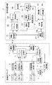
図1に、実施の形態1に係る超音波診断装置の構成を示す。超音波診断装置は、超音波プローブ1と、この超音波プローブ1と無線通信により接続された診断装置本体2とを備えている。
Embodiments of the present invention will be described below with reference to the accompanying drawings.
FIG. 1 shows the configuration of the ultrasonic diagnostic apparatus according to the first embodiment. The ultrasonic diagnostic apparatus includes an
超音波プローブ1は、1次元又は2次元のアレイ状に配列された複数の超音波トランスデューサ3を有し、これら超音波トランスデューサ3にそれぞれ対応して受信信号処理部4が接続され、さらに受信信号処理部4にパラレル/シリアル変換部5を介して無線通信部6が接続されている。また、複数の超音波トランスデューサ3に送信駆動部7を介して送信制御部8が接続され、複数の受信信号処理部4に受信制御部9が接続され、無線通信部6に通信制御部10が接続されている。そして、パラレル/シリアル変換部5、送信制御部8、受信制御部9および通信制御部10にプローブ制御部11が接続されている。
The
複数の超音波トランスデューサ3は、それぞれ送信駆動部7から供給される駆動信号に従って超音波を送信すると共に被検体からの超音波エコーを受信して受信信号を出力する。各超音波トランスデューサ3は、例えば、PZT(チタン酸ジルコン酸鉛)に代表される圧電セラミックや、PVDF(ポリフッ化ビニリデン)に代表される高分子圧電素子、PMN−PT(マグネシウムニオブ酸・チタン酸鉛固溶体)に代表される圧電単結晶等からなる圧電体の両端に電極を形成した振動子によって構成される。
そのような振動子の電極に、パルス状又は連続波の電圧を印加すると、圧電体が伸縮し、それぞれの振動子からパルス状又は連続波の超音波が発生して、それらの超音波の合成により超音波ビームが形成される。また、それぞれの振動子は、伝搬する超音波を受信することにより伸縮して電気信号を発生し、それらの電気信号は、超音波の受信信号として出力される。
Each of the plurality of
When a pulsed or continuous wave voltage is applied to the electrodes of such a vibrator, the piezoelectric body expands and contracts, and pulsed or continuous wave ultrasonic waves are generated from the respective vibrators, and the synthesis of those ultrasonic waves. As a result, an ultrasonic beam is formed. In addition, each transducer generates an electric signal by expanding and contracting by receiving propagating ultrasonic waves, and these electric signals are output as ultrasonic reception signals.
送信駆動部7は、例えば、複数のパルサを含んでおり、送信制御部8によって選択された送信遅延パターンに基づいて、複数の超音波トランスデューサ3から送信される超音波が被検体内の組織のエリアをカバーする幅広の超音波ビームを形成するようにそれぞれの駆動信号の遅延量を調節して複数の超音波トランスデューサ3に供給する。
各受信信号処理部4は、受信制御部9の制御の下で、対応する超音波トランスデューサ3から出力される受信信号に対して直交検波処理又は直交サンプリング処理を施すことにより複素ベースバンド信号を生成し、複素ベースバンド信号をサンプリングすることにより、組織のエリアの情報を含むサンプルデータを生成して、サンプルデータをパラレル/シリアル変換部5に供給する。受信信号処理部4は、複素ベースバンド信号をサンプリングして得られるデータに高能率符号化のためのデータ圧縮処理を施すことによりサンプルデータを生成してもよい。
パラレル/シリアル変換部5は、複数の受信信号処理部4によって生成されたパラレルのサンプルデータを、シリアルのサンプルデータに変換する。
The
Each reception
The parallel /
無線通信部6は、シリアルのサンプルデータに基づいてキャリアを変調して伝送信号を生成し、伝送信号をアンテナに供給してアンテナから電波を送信することにより、シリアルのサンプルデータを送信する。変調方式としては、例えば、ASK(Amplitude Shift Keying)、PSK(Phase Shift Keying)、QPSK(Quadrature Phase Shift Keying)、16QAM(16 Quadrature Amplitude Modulation)等が用いられる。
無線通信部6は、診断装置本体2との間で無線通信を行うことにより、サンプルデータを診断装置本体2に送信すると共に、診断装置本体2から各種の制御信号を受信して、受信された制御信号を通信制御部10に出力する。通信制御部10は、プローブ制御部11によって設定された送信電波強度でサンプルデータの送信が行われるように無線通信部6を制御すると共に、無線通信部6が受信した各種の制御信号をプローブ制御部11に出力する。
The wireless communication unit 6 modulates a carrier based on serial sample data to generate a transmission signal, supplies the transmission signal to the antenna, and transmits radio waves from the antenna, thereby transmitting serial sample data. As the modulation scheme, for example, ASK (Amplitude Shift Keying), PSK (Phase Shift Keying), QPSK (Quadrature Phase Shift Keying), 16QAM (16 Quadrature Amplitude Modulation), and the like are used.
The wireless communication unit 6 performs wireless communication with the diagnostic apparatus
プローブ制御部11は、診断装置本体2から送信される各種の制御信号に基づいて、超音波プローブ1の各部の制御を行う。
超音波プローブ1には、図示しないバッテリが内蔵され、このバッテリから超音波プローブ1内の各回路に電源供給が行われる。
なお、超音波プローブ1は、リニアスキャン方式、コンベックススキャン方式、セクタスキャン方式等の体外式プローブでもよいし、ラジアルスキャン方式等の超音波内視鏡用プローブでもよい。
The
The
The
一方、診断装置本体2は、無線通信部21を有し、この無線通信部21にシリアル/パラレル変換部22を介してデータ格納部23が接続され、データ格納部23に画像生成部24が接続されている。さらに、画像生成部24に表示制御部25を介して表示部26が接続されている。また、無線通信部21に通信制御部27が接続され、シリアル/パラレル変換部22、画像生成部24、表示制御部25および通信制御部27に本体制御部28が接続されている。さらに、本体制御部28には、オペレータが入力操作を行うための操作部29と、動作プログラムを格納する格納部30がそれぞれ接続されている。
On the other hand, the
無線通信部21は、超音波プローブ1との間で無線通信を行うことにより、各種の制御信号を超音波プローブ1に送信する。また、無線通信部21は、アンテナによって受信される信号を復調することにより、シリアルのサンプルデータを出力する。
通信制御部27は、本体制御部28によって設定された送信電波強度で各種の制御信号の送信が行われるように無線通信部21を制御する。
シリアル/パラレル変換部22は、無線通信部21から出力されるシリアルのサンプルデータを、パラレルのサンプルデータに変換する。データ格納部23は、メモリまたはハードディスク等によって構成され、シリアル/パラレル変換部22によって変換された少なくとも1フレーム分のサンプルデータを格納する。
画像生成部24は、データ格納部23から読み出される1フレーム毎のサンプルデータに受信フォーカス処理を施して、超音波診断画像を表す画像信号を生成する。画像生成部24は、整相加算部31と画像処理部32とを含んでいる。
The
The
The serial /
The
整相加算部31は、本体制御部28において設定された受信方向に応じて、予め記憶されている複数の受信遅延パターンの中から1つの受信遅延パターンを選択し、選択された受信遅延パターンに基づいて、サンプルデータによって表される複数の複素ベースバンド信号にそれぞれの遅延を与えて加算することにより、受信フォーカス処理を行う。この受信フォーカス処理により、超音波エコーの焦点が絞り込まれたベースバンド信号(音線信号)が生成される。
The
画像処理部32は、整相加算部31によって生成される音線信号に基づいて、被検体内の組織に関する断層画像情報であるBモード画像信号を生成する。画像処理部32は、STC(sensitivity time control)部と、DSC(digital scan converter:デジタル・スキャン・コンバータ)とを含んでいる。STC部は、音線信号に対して、超音波の反射位置の深度に応じて、距離による減衰の補正を施す。DSCは、STC部によって補正された音線信号を通常のテレビジョン信号の走査方式に従う画像信号に変換(ラスター変換)し、階調処理等の必要な画像処理を施すことにより、Bモード画像信号を生成する。
表示制御部25は、画像生成部24によって生成される画像信号に基づいて、表示部26に超音波診断画像を表示させる。表示部26は、例えば、LCD等のディスプレイ装置を含んでおり、表示制御部25の制御の下で、超音波診断画像を表示する。
本体制御部28は、操作者により操作部29から入力された各種の指令信号等に基づいて、診断装置本体2内の各部の制御を行うものである。
The
The
The main
このような診断装置本体2において、シリアル/パラレル変換部22、画像生成部24、表示制御部25、通信制御部27および本体制御部28は、CPUと、CPUに各種の処理を行わせるための動作プログラムから構成されるが、それらをデジタル回路で構成してもよい。上記の動作プログラムは、格納部30に格納される。格納部30における記録媒体としては、内蔵のハードディスクの他に、フレキシブルディスク、MO、MT、RAM、CD−ROMまたはDVD−ROM等を用いることができる。
In such a diagnostic apparatus
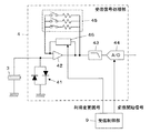
ここで、超音波プローブ1内における各受信信号処理部4の内部構成を図2に示す。受信信号処理部4は、対応する超音波トランスデューサ3に入力保護用のクリップ回路41を介して接続されたプリアンプ42と、このプリアンプ42の出力端にローパスフィルタ43を介して接続されたA/Dコンバータ44を有している。また、利得設定回路45と利得変更回路46がそれぞれプリアンプ42に並列に接続されている。
Here, FIG. 2 shows an internal configuration of each received
クリップ回路41は、超音波トランスデューサ3からプリアンプ42に設定値を超える電圧の信号が入力されることを防止する。プリアンプ42は、超音波トランスデューサ3から出力された受信信号を増幅する。利得設定回路45は、被検体およびその診断部位等に応じてプリアンプ42の利得を適宜設定するものである。
利得変更回路46は、受信制御部9から入力される利得変更信号に基づいて、利得設定回路45により設定されたプリアンプ42の利得の変更を行う。
ローパスフィルタ43は、プリアンプ42で増幅された受信信号から信号検出に用いられない高周波成分を除去する。A/Dコンバータ44は、受信制御部9から入力される変換開始信号に基づき、ローパスフィルタ43で高周波成分が除去されたアナログの受信信号をデジタル信号に変換する。
The
The
The low-
このような構成により受信信号処理部4による受信信号のA/D変換可能範囲が決定され、A/Dコンバータ44のダイナミックレンジに応じた分解能で受信信号のA/D変換が行われる。
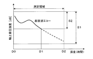
このとき、例えば図3に示されるように、深度D0からD2にまで及ぶ測定領域に対し、超音波ビームの送受信を行う際に、この測定領域内の深度方向の全域から戻ってくる超音波エコーの強度をすべてカバーするような広い強度範囲S1に対応して受信信号処理部4によるA/D変換可能範囲が設定されていれば、超音波エコーの受信に起因して超音波トランスデューサ3から出力される受信信号を受信信号処理部4のA/Dコンバータ44で一度にA/D変換することができる。ただし、受信信号処理部4のA/Dコンバータ44のダイナミックレンジを一定とした場合には、広い強度範囲に対応してA/D変換可能範囲を設定するほど、A/D変換の分解能は低くなってしまう。
With this configuration, the A / D conversion possible range of the received signal by the received
At this time, for example, as shown in FIG. 3, when an ultrasonic beam is transmitted / received to / from a measurement region extending from a depth D0 to D2, an ultrasonic echo returned from the entire depth direction in the measurement region. If the A / D conversion possible range by the received
これに対し、測定領域内の各部から戻ってくる超音波エコーの強度の一部のみの強度範囲S2に対応して受信信号処理部4によるA/D変換可能範囲が設定されると、A/D変換可能範囲外の強度を有する、深度D1からD2までの点線で描かれた部分の超音波エコーに対して受信信号のA/D変換を行うことができなくなるが、深度D0からD1までの実線で描かれた部分の超音波エコーに対しては、広い強度範囲S1に対応してA/D変換可能範囲が設定された場合に比べ、より高い分解能で受信信号のA/D変換を行うことが可能となる。
On the other hand, when the A / D conversion possible range by the reception
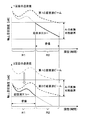
そこで、この実施の形態1においては、図4に示されるように、受信信号処理部4によるA/D変換可能範囲が、測定領域内の深度方向の全域から戻ってくる超音波エコーの強度をすべてカバーする強度範囲に対して1/2程度の強度範囲に対応するように設定されると共に、測定領域が、それぞれ受信信号処理部4によるA/D変換可能範囲より小さい振幅範囲の受信信号が得られるような第1の測定深度領域R1と第2の測定深度領域R2に分割される。そして、1回の超音波ビームの送受信では、超音波エコーに対して受信信号のすべてをA/D変換することができないので、第1の測定深度領域R1と第2の測定深度領域R2に対して同一の超音波ビームを2回送信し、受信信号処理部4によるA/D変換可能範囲をずらして、第1の測定深度領域R1に対する超音波エコーの受信と第2の測定深度領域R2に対する超音波エコーの受信を行うことで、超音波エコーに対する受信信号のすべてのA/D変換が行われる。
Therefore, in the first embodiment, as shown in FIG. 4, the A / D conversion possible range by the received
すなわち、1回目の超音波ビームの送受信においては、測定領域内の深度方向の全域からの超音波エコーの強度をすべてカバーするような強度範囲に対して1/2程度の強度範囲で且つ第1の測定深度領域R1からの超音波エコーの強度範囲に対応する第1のA/D変換可能範囲が設定され、2回目の超音波ビームの送受信においては、利得変更回路46でプリアンプ42の利得を変更することにより第1のA/D変換可能範囲と同様のビット幅を有しながらも第2の測定深度領域R2からの超音波エコーの強度範囲に対応する第2のA/D変換可能範囲が設定される。
That is, in the first transmission / reception of the ultrasonic beam, the first intensity range is about ½ of the intensity range that covers all the intensity of the ultrasonic echoes from the entire depth direction in the measurement area. A first A / D conversion possible range corresponding to the intensity range of the ultrasonic echo from the measurement depth region R1 is set, and in the second transmission / reception of the ultrasonic beam, the
そして、1回目の超音波ビームの送受信により、第1のA/D変換可能範囲でもって第1の測定深度領域R1に対応する受信信号のA/D変換が行われ、2回目の超音波ビームの送受信により、第2のA/D変換可能範囲でもって第2の測定深度領域R2に対応する受信信号のA/D変換が行われる。
なお、第1のA/D変換可能範囲と第2のA/D変換可能範囲は、互いに一部が重複するように設定されている。
また、図4では、第1のA/D変換可能範囲および第2のA/D変換可能範囲がそれぞれ超音波エコーの強度レベルに換算されたものとして示されている。
Then, by the first transmission / reception of the ultrasonic beam, the A / D conversion of the reception signal corresponding to the first measurement depth region R1 is performed within the first A / D conversion possible range, and the second ultrasonic beam The A / D conversion of the received signal corresponding to the second measurement depth region R2 is performed with the second A / D conversion possible range by the transmission / reception of.
Note that the first A / D convertible range and the second A / D convertible range are set to partially overlap each other.
Further, in FIG. 4, the first A / D convertible range and the second A / D convertible range are shown as being converted into ultrasonic echo intensity levels.
次に、実施の形態1の動作について説明する。
まず、操作者により診断装置本体2の操作部29から超音波診断に係る測定領域が入力されると、本体制御部28は、測定領域を深度の浅い第1の測定深度領域R1と深度の深い第2の測定深度領域R2に分割し、第1の測定深度領域R1から戻ってくる超音波エコーの強度範囲に対応する第1のA/D変換可能範囲が設定されるように、無線通信により超音波プローブ1の受信制御部9を介して各受信信号処理部4を制御する。第1のA/D変換可能範囲は、各受信信号処理部4の利得変更回路46でプリアンプ42の利得を調整することにより設定することができる。
なお、第1の測定深度領域R1からの超音波エコーの強度範囲および第2の測定深度領域R2からの超音波エコーの強度範囲を認識するために、診断に先立って被検体に対し超音波ビームによるプレスキャンを行い、実際に超音波エコーを受信することもできる。
Next, the operation of the first embodiment will be described.
First, when an operator inputs a measurement region related to ultrasonic diagnosis from the
In addition, in order to recognize the intensity range of the ultrasonic echo from the first measurement depth region R1 and the intensity range of the ultrasonic echo from the second measurement depth region R2, an ultrasonic beam is applied to the subject prior to diagnosis. It is also possible to perform pre-scanning and actually receive ultrasonic echoes.
そして、超音波診断が開始されると、超音波プローブ1の送信駆動部7から供給される駆動信号に従って複数の超音波トランスデューサ3から第1の超音波ビームが送信され、被検体の第1の測定深度領域R1からの超音波エコーを受信した各超音波トランスデューサ3から出力された受信信号がそれぞれ対応する受信信号処理部4に供給される。
受信信号は、受信信号処理部4内のプリアンプ42で増幅され、ローパスフィルタ43で高周波成分が除去された後にA/Dコンバータ44に入力される。このとき、利得変更回路46によりプリアンプ42の利得が調整されることで第1のA/D変換可能範囲が設定されているので、第1の測定深度領域R1からの超音波エコーに対応する受信信号はA/Dコンバータ44のダイナミックレンジに応じた分解能でA/D変換される。
When the ultrasound diagnosis is started, the first ultrasound beam is transmitted from the plurality of
The received signal is amplified by the
このようにしてA/Dコンバータ44で受信信号にA/D変換を施すことによりサンプルデータが生成され、このサンプルデータがパラレル/シリアル変換部5でシリアル化された後に無線通信部6から診断装置本体2へ無線伝送される。診断装置本体2の無線通信部21で受信されたサンプルデータは、シリアル/パラレル変換部22でパラレルのデータに変換され、データ格納部23に格納される。
In this way, sample data is generated by performing A / D conversion on the received signal by the A /
次に、診断装置本体2の本体制御部28からの指令に基づき、超音波プローブ1の受信制御部9により各受信信号処理部4の利得変更回路46でプリアンプ42の利得が増加され、各受信信号処理部4に、深度の深い第2の測定深度領域R2から戻ってくる超音波エコーの強度範囲に対応する第2のA/D変換可能範囲が設定される。
Next, based on a command from the main
そして、超音波プローブ1の送信駆動部7から供給される駆動信号に従って複数の超音波トランスデューサ3から第1の超音波ビームと同一の第2の超音波ビームが同一の音線上に送信され、今度は第2の測定深度領域R2からの超音波エコーを受信した各超音波トランスデューサ3から出力された受信信号がそれぞれ対応する受信信号処理部4に供給される。
受信信号は、受信信号処理部4内のプリアンプ42で増幅され、ローパスフィルタ43で高周波成分が除去された後にA/Dコンバータ44に入力される。このとき、利得変更回路46によりプリアンプ42の利得が変更されることで第2のA/D変換可能範囲が設定されているので、第2の測定深度領域R2からの超音波エコーに対応する受信信号はA/Dコンバータ44のダイナミックレンジに応じた分解能でA/D変換される。
Then, in accordance with the drive signal supplied from the
The received signal is amplified by the
A/Dコンバータ44で受信信号にA/D変換を施すことにより生成されたサンプルデータがパラレル/シリアル変換部5でシリアル化された後に無線通信部6から診断装置本体2へ無線伝送され、診断装置本体2のシリアル/パラレル変換部22でパラレルのデータに変換され、データ格納部23に格納される。
Sample data generated by performing A / D conversion on the received signal by the A /
このようにして各音線上の第1の測定深度領域R1に対応するサンプルデータおよび第2の測定深度領域R2に対応するサンプルデータが順次データ格納部23に格納される。1フレーム分のサンプルデータがデータ格納部23に格納されると、これら第1の測定深度領域R1に対応するサンプルデータおよび第2の測定深度領域R2に対応するサンプルデータを用いて画像生成部24で画像信号が生成され、この画像信号に基づき表示制御部25により超音波診断画像が表示部26に表示される。
In this way, the sample data corresponding to the first measurement depth region R1 and the sample data corresponding to the second measurement depth region R2 on each sound ray are sequentially stored in the
以上のように、測定領域を第1の測定深度領域R1と第2の測定深度領域R2に分割し、1回目の超音波ビームの送受信により、第1のA/D変換可能範囲で第1の測定深度領域R1に対応する受信信号のA/D変換を行い、2回目の超音波ビームの送受信により、第2のA/D変換可能範囲で第2の測定深度領域R2に対応する受信信号のA/D変換を行うので、各受信信号処理部4内のA/Dコンバータ44のダイナミックレンジを有効に活用することができ、高画質の超音波画像の生成と省電力化を図ることが可能となる。
As described above, the measurement region is divided into the first measurement depth region R1 and the second measurement depth region R2, and the first A / D conversion possible range is obtained by the first transmission / reception of the ultrasonic beam. A / D conversion of the reception signal corresponding to the measurement depth region R1 is performed, and the reception signal corresponding to the second measurement depth region R2 is within the second A / D conversion possible range by the second transmission / reception of the ultrasonic beam. Since A / D conversion is performed, the dynamic range of the A /
この実施の形態1においては、第1の測定深度領域R1と第2の測定深度領域R2に対応して同一の音線上に2回の超音波ビームの送信が行われるが、例えば第1の超音波ビームおよび第2の超音波ビームを、それぞれ2本の音線領域にまたがる幅狭部を有するような幅広の超音波ビームとして2本の音線毎に送受信を行うことにより、フレームレートの低下を来すことなく、超音波画像を生成することができる。 In the first embodiment, the ultrasonic beam is transmitted twice on the same sound ray corresponding to the first measurement depth region R1 and the second measurement depth region R2. The frame rate is reduced by transmitting / receiving the acoustic beam and the second ultrasonic beam as a wide ultrasonic beam having a narrow portion that extends over each of the two acoustic ray regions, for every two acoustic rays. An ultrasonic image can be generated without bringing
実施の形態2
上記の実施の形態1では、1回目の超音波ビームの送受信と2回目の超音波ビームの送受信において、同一の超音波ビームを送信し、第1の測定深度領域R1に対する第1のA/D変換可能範囲と第2の測定深度領域R2に対する第2のA/D変換可能範囲とを互いにずらすことで、測定領域内の深度方向の全域からの超音波エコーに対応する受信信号のA/D変換を行った。これに対し、実施の形態2は、図5に示されるように、1回目の超音波ビームの送受信と2回目の超音波ビームの送受信において、各受信信号処理部4によるA/D変換可能範囲を同一とし、送信する超音波ビームの振幅を変化させることで、超音波ビームの強度を変化させ、測定領域内の深度方向の全域からの超音波エコーに対応する受信信号のA/D変換を行うようにしたものである。
In the first embodiment, in the first transmission / reception of the ultrasonic beam and the second transmission / reception of the ultrasonic beam, the same ultrasonic beam is transmitted, and the first A / D for the first measurement depth region R1 is transmitted. By shifting the convertible range and the second A / D convertible range for the second measurement depth region R2 from each other, the A / D of the received signal corresponding to the ultrasonic echoes from the entire depth direction in the measurement region Conversion was performed. On the other hand, in the second embodiment, as shown in FIG. 5, in the first transmission / reception of the ultrasonic beam and the second transmission / reception of the ultrasonic beam, the A / D conversion possible range by each reception
実施の形態1と同様に、本体制御部28により、測定領域が深度の小さい第1の測定深度領域R1と深度の大きい第2の測定深度領域R2に分割され、1回目の第1の超音波ビームの送受信により、各受信信号処理部4に設定されたA/D変換可能範囲で深度の大きい第2の測定深度領域R2に対応する受信信号のA/D変換が行われ、第2の測定深度領域R2に対応するサンプルデータが診断装置本体2のデータ格納部23に格納される。
Similarly to the first embodiment, the main
次に、診断装置本体2の本体制御部28からの指令に基づき、超音波プローブ1の送信制御部8の制御の下で、送信駆動部7から供給される駆動信号に従って複数の超音波トランスデューサ3から第1の超音波ビームより振幅の小さな第2の超音波ビームが送信される。これにより、1回目の第1の超音波ビームの送受信のときよりも強度の小さな超音波エコーが得られ、深度の小さい第1の測定深度領域R1からの超音波エコーを受信した各超音波トランスデューサ3から出力された受信信号がそれぞれ対応する受信信号処理部4に供給され、A/Dコンバータ44のダイナミックレンジに応じた分解能でA/D変換されて、第1の測定深度領域R1に対応するサンプルデータが診断装置本体2のデータ格納部23に格納される。
Next, based on a command from the main
このようにしてデータ格納部23に格納された第1の測定深度領域R1に対応するサンプルデータおよび第2の測定深度領域R2に対応するサンプルデータを用いて画像生成部24で画像信号が生成され、この画像信号に基づき表示制御部25により超音波診断画像が表示部26に表示される。
In this way, an image signal is generated by the
この実施の形態2においても、実施の形態1と同様に、各受信信号処理部4内のA/Dコンバータ44のダイナミックレンジを有効に活用することができ、高画質の超音波画像の生成と省電力化を図ることが可能となる。
なお、送信駆動部7から供給される駆動信号に従って複数の超音波トランスデューサ3から送信される超音波ビームの振幅の代わりに、あるいは、振幅と共に、超音波ビームの波数および中心周波数の少なくとも一方を変化させても、送信する超音波ビームの強度を変化させることができる。
In the second embodiment, as in the first embodiment, the dynamic range of the A /
It should be noted that at least one of the wave number and the center frequency of the ultrasonic beam is changed in place of or together with the amplitude of the ultrasonic beam transmitted from the plurality of
実施の形態3
上記の実施の形態2では、1回目の超音波ビームの送受信と2回目の超音波ビームの送受信において、各受信信号処理部4によるA/D変換可能範囲を同一とし、送信する超音波ビームの振幅を変化させることで、測定領域内の深度方向の全域からの超音波エコーに対応する受信信号のA/D変換を行ったが、送信する超音波ビームの振幅を変化させる代わりに、図6に示されるように、送信する超音波ビームの焦点位置を変化させてもよい。
In the second embodiment, the A / D conversion possible range by each received
実施の形態1および2と同様に、本体制御部28により、測定領域が第1の測定深度領域R1と第2の測定深度領域R2に分割され、1回目の第1の超音波ビームの送受信により、各受信信号処理部4に設定されたA/D変換可能範囲で第1の測定深度領域R1に対応する受信信号のA/D変換が行われ、第1の測定深度領域R1に対応するサンプルデータが診断装置本体2のデータ格納部23に格納される。
As in the first and second embodiments, the main
次に、診断装置本体2の本体制御部28からの指令に基づき、超音波プローブ1の送信制御部8の制御の下で、第1の超音波ビームにおける焦点位置とは異なる焦点位置を有するように、送信駆動部7から供給される駆動信号に従って複数の超音波トランスデューサ3から第2の超音波ビームが送信される。これにより、第1の超音波ビームに対する超音波エコーとは異なる波形の超音波エコーが得られ、第2の測定深度領域R2からの超音波エコーを受信した各超音波トランスデューサ3から出力された受信信号がそれぞれ対応する受信信号処理部4に供給され、A/Dコンバータ44のダイナミックレンジに応じた分解能でA/D変換されて、第2の測定深度領域R2に対応するサンプルデータが診断装置本体2のデータ格納部23に格納される。
Next, under the control of the
このようにしてデータ格納部23に格納された第1の測定深度領域R1に対応するサンプルデータおよび第2の測定深度領域R2に対応するサンプルデータを用いて画像生成部24で画像信号が生成され、この画像信号に基づき表示制御部25により超音波診断画像が表示部26に表示される。
なお、第2の測定深度領域R2からの超音波エコーが受信信号処理部4によるA/D変換可能範囲に対応した強度を有するように第2の超音波ビームの焦点位置を形成する必要がある。
In this way, an image signal is generated by the
Note that it is necessary to form the focal position of the second ultrasonic beam so that the ultrasonic echo from the second measurement depth region R2 has an intensity corresponding to the A / D convertible range by the reception
この実施の形態3においても、実施の形態1および2と同様に、各受信信号処理部4内のA/Dコンバータ44のダイナミックレンジを有効に活用することができ、高画質の超音波画像の生成と省電力化を図ることが可能となる。
In the third embodiment, as in the first and second embodiments, the dynamic range of the A /
上記の実施の形態2では、送信する超音波ビームの振幅を変化させることにより、また、実施の形態3では、送信する超音波ビームの焦点位置を変化させることにより、それぞれ1回目と2回目とで送信される超音波ビームの強度を制御したが、これに限るものではなく、超音波ビームの送信に使用されるアレイトランスデューサの素子数すなわち開口幅を変化させることによっても、送信される超音波ビームの強度を制御することができる。このため、複数の測定深度領域に対応して超音波ビームの送信に使用される超音波トランスデューサ3の数が変化するように送信駆動部7を制御しても、同様の効果が得られる。具体的には、深度が小さい測定深度領域ほど超音波ビームの送信に使用される超音波トランスデューサ3の数が少なくなるように送信駆動部7が制御される。
さらに、1回目と2回目とで、送信する超音波ビームの振幅、焦点位置、および使用される超音波トランスデューサ3の数のうち2つ以上を同時に変化させることもできる。
In the second embodiment, by changing the amplitude of the ultrasonic beam to be transmitted, and in the third embodiment, by changing the focal position of the ultrasonic beam to be transmitted, the first time and the second time respectively. Although the intensity of the ultrasonic beam transmitted in (1) was controlled, the present invention is not limited to this, but the transmitted ultrasonic wave can also be changed by changing the number of elements of the array transducer used for transmitting the ultrasonic beam, that is, the aperture width. The intensity of the beam can be controlled. For this reason, even if the
Furthermore, two or more of the amplitude of the ultrasonic beam to be transmitted, the focal position, and the number of
上記の実施の形態1〜3では、測定領域を第1の測定深度領域R1と第2の測定深度領域R2に2分割したが、これに限るものではなく、それぞれ受信信号処理部4による受信信号のA/D変換可能範囲より小さい振幅範囲の受信信号が得られる3つ以上の測定深度領域に分割し、分割された複数の測定深度領域にそれぞれ対応して超音波ビームの送信を複数回行うことで、測定領域内の深度方向の全域からの超音波エコーに対応する受信信号をA/D変換することもできる。
この場合、複数の測定深度領域に対応して同一の音線上に順次送信される複数の超音波ビームを、それぞれ複数の音線領域にまたがる幅狭部を有するような幅広の超音波ビームとし、複数の音線毎に送受信を行うことにより、フレームレートの低下を抑制しつつ超音波画像を生成することができる。
In the above first to third embodiments, the measurement region is divided into the first measurement depth region R1 and the second measurement depth region R2. However, the present invention is not limited to this, and the reception signal by the reception
In this case, a plurality of ultrasonic beams that are sequentially transmitted on the same sound ray corresponding to a plurality of measurement depth regions, and a wide ultrasonic beam having a narrow portion that spans each of the plurality of sound ray regions, By performing transmission / reception for each of the plurality of sound rays, it is possible to generate an ultrasonic image while suppressing a decrease in the frame rate.
上記の実施の形態2および3では、1回目の超音波ビームの送受信と2回目の超音波ビームの送受信において、各受信信号処理部4によるA/D変換可能範囲を変化させることなく、同一のA/D変換可能範囲を用いるので、図2に示した利得変更回路46は不要となる。
In the above-described second and third embodiments, the same transmission / reception of the first ultrasonic beam and the second transmission / reception of the ultrasonic beam are performed without changing the A / D conversion possible range by each reception
上記の実施の形態1〜3では、超音波プローブ1と診断装置本体2とが互いに無線通信により接続されていたが、これに限るものではなく、接続ケーブルを介して超音波プローブ1が診断装置本体2に接続されていてもよい。この場合には、超音波プローブ1の無線通信部6および通信制御部10、診断装置本体2の無線通信部21および通信制御部27等は不要となる。
In the first to third embodiments, the
1 超音波プローブ、2 診断装置本体、3 超音波トランスデューサ、4 受信信号処理部、5 パラレル/シリアル変換部、6 無線通信部、7 送信駆動部、8 送信制御部、9 受信制御部、10 通信制御部、11 プローブ制御部、21 無線通信部、22 シリアル/パラレル変換部、23 データ格納部、24 画像生成部、25 表示制御部、26 表示部、27 通信制御部、28 本体制御部、29 操作部、30 格納部、31 整相加算部、32 画像処理部、41 クリップ回路、42 プリアンプ、43 ローパスフィルタ、44 A/Dコンバータ、45 利得設定回路、46 利得変更回路、R1 第1の測定深度領域、R2 第2の測定深度領域。
DESCRIPTION OF
Claims (9)
前記受信信号処理部は、測定領域内の深度方向の全域から得られる受信信号の振幅範囲より小さなA/D変換可能範囲を有し、
前記測定領域をそれぞれ前記受信信号処理部のA/D変換可能範囲より小さい振幅範囲の受信信号が得られる複数の測定深度領域に分割し且つこれら複数の測定深度領域にそれぞれ対応して前記アレイトランスデューサから超音波ビームの送信が複数回行われるように前記送信駆動部を制御すると共に各測定深度領域に対応して送信された超音波ビームにより各測定深度領域に対する受信データが得られるように前記受信信号処理部を制御する制御部を備えたことを特徴とする超音波診断装置。 Based on the drive signal supplied from the transmission drive unit, an ultrasonic beam is transmitted from the array transducer of the ultrasonic probe toward the subject, and a reception signal output from the array transducer that has received the ultrasonic echo from the subject. An ultrasonic diagnostic apparatus that generates an ultrasonic image based on reception data obtained by processing the received signal processing unit,
The reception signal processing unit has an A / D conversion possible range smaller than the amplitude range of the reception signal obtained from the entire depth direction in the measurement region,
Each of the array transducers is divided into a plurality of measurement depth regions from which a reception signal having an amplitude range smaller than the A / D convertible range of the reception signal processing unit can be obtained, and the array transducer corresponding to each of the plurality of measurement depth regions. The transmission driving unit is controlled so that transmission of the ultrasonic beam is performed a plurality of times, and the reception data for each measurement depth region is obtained by the ultrasonic beam transmitted corresponding to each measurement depth region. An ultrasonic diagnostic apparatus comprising a control unit for controlling a signal processing unit.
前記受信信号処理部は、測定領域内の深度方向の全域から得られる受信信号の振幅範囲より小さなA/D変換可能範囲を有し、
前記測定領域をそれぞれ前記受信信号処理部のA/D変換可能範囲より小さい振幅範囲の受信信号が得られる複数の測定深度領域に分割し、
前記複数の測定深度領域にそれぞれ対応して前記アレイトランスデューサから超音波ビームの送信が複数回行われるように前記送信駆動部を制御し、
各測定深度領域に対応して送信された超音波ビームにより各測定深度領域に対する受信データが得られるように前記受信信号処理部を制御する
ことを特徴とする超音波画像生成方法。 Based on the drive signal supplied from the transmission drive unit, an ultrasonic beam is transmitted from the array transducer of the ultrasonic probe toward the subject, and a reception signal output from the array transducer that has received the ultrasonic echo from the subject. An ultrasonic image generation method for generating an ultrasonic image based on reception data obtained by processing a received signal processing unit,
The reception signal processing unit has an A / D conversion possible range smaller than the amplitude range of the reception signal obtained from the entire depth direction in the measurement region,
The measurement area is divided into a plurality of measurement depth areas in which a reception signal having an amplitude range smaller than the A / D convertible range of the reception signal processing unit is obtained,
Controlling the transmission driving unit so that transmission of an ultrasonic beam from the array transducer is performed a plurality of times corresponding to each of the plurality of measurement depth regions,
An ultrasonic image generation method, wherein the reception signal processing unit is controlled so that reception data for each measurement depth region is obtained by an ultrasonic beam transmitted corresponding to each measurement depth region.
Priority Applications (3)
| Application Number | Priority Date | Filing Date | Title |
|---|---|---|---|
| JP2011126190A JP5518790B2 (en) | 2011-06-06 | 2011-06-06 | Ultrasonic diagnostic apparatus and ultrasonic image generation method |
| US13/466,424 US20120310095A1 (en) | 2011-06-06 | 2012-05-08 | Ultrasound diagnostic apparatus and ultrasound image producing method |
| CN2012101647753A CN102813529A (en) | 2011-06-06 | 2012-05-24 | Ultrasound diagnostic apparatus and ultrasound image producing method |
Applications Claiming Priority (1)
| Application Number | Priority Date | Filing Date | Title |
|---|---|---|---|
| JP2011126190A JP5518790B2 (en) | 2011-06-06 | 2011-06-06 | Ultrasonic diagnostic apparatus and ultrasonic image generation method |
Publications (2)
| Publication Number | Publication Date |
|---|---|
| JP2012249928A true JP2012249928A (en) | 2012-12-20 |
| JP5518790B2 JP5518790B2 (en) | 2014-06-11 |
Family
ID=47262199
Family Applications (1)
| Application Number | Title | Priority Date | Filing Date |
|---|---|---|---|
| JP2011126190A Expired - Fee Related JP5518790B2 (en) | 2011-06-06 | 2011-06-06 | Ultrasonic diagnostic apparatus and ultrasonic image generation method |
Country Status (3)
| Country | Link |
|---|---|
| US (1) | US20120310095A1 (en) |
| JP (1) | JP5518790B2 (en) |
| CN (1) | CN102813529A (en) |
Cited By (2)
| Publication number | Priority date | Publication date | Assignee | Title |
|---|---|---|---|---|
| JP2016209452A (en) * | 2015-05-13 | 2016-12-15 | キヤノン株式会社 | Subject information acquisition device |
| JP2019041831A (en) * | 2017-08-30 | 2019-03-22 | キヤノン株式会社 | Ultrasonic probe and photoacoustic apparatus equipped with the same |
Families Citing this family (7)
| Publication number | Priority date | Publication date | Assignee | Title |
|---|---|---|---|---|
| US20120123270A1 (en) * | 2009-07-29 | 2012-05-17 | Koninklijke Philips Electronics N.V. | Device with integrated ultrasound transducers and flow sensor |
| JP5769677B2 (en) * | 2011-11-10 | 2015-08-26 | 富士フイルム株式会社 | Ultrasonic diagnostic apparatus and ultrasonic image generation method |
| JP5769678B2 (en) | 2011-11-10 | 2015-08-26 | 富士フイルム株式会社 | Ultrasonic diagnostic apparatus and ultrasonic image generation method |
| US20140206968A1 (en) * | 2013-01-24 | 2014-07-24 | Flextronics Ap, Llc | Ultrasonic Sensor and Method of Operating the Same |
| KR101496167B1 (en) * | 2014-07-08 | 2015-02-26 | 주식회사 힐세리온 | Portable Ultrasonic Diagnostic apparatus and power efficiency improvement method thereof |
| CN107390163B (en) * | 2016-05-16 | 2020-10-20 | 株式会社理光 | Mobile device, positioning device and method thereof, and area defining system and method |
| US10946193B2 (en) * | 2017-02-28 | 2021-03-16 | Pulse Biosciences, Inc. | Pulse generator with independent panel triggering |
Citations (5)
| Publication number | Priority date | Publication date | Assignee | Title |
|---|---|---|---|---|
| JPS53142071A (en) * | 1977-05-17 | 1978-12-11 | Aloka Co Ltd | Ultrasonic diagnosing device |
| JPH01195845A (en) * | 1988-02-01 | 1989-08-07 | Hitachi Medical Corp | Ultrasonic diagnoser |
| JPH11313823A (en) * | 1998-03-06 | 1999-11-16 | Hitachi Medical Corp | Ultrasonic image device |
| JP2001161686A (en) * | 1999-12-10 | 2001-06-19 | Hitachi Medical Corp | Ultrasonic imaging apparatus |
| JP2003010187A (en) * | 2001-07-04 | 2003-01-14 | Hitachi Medical Corp | Ultrasonograph |
Family Cites Families (5)
| Publication number | Priority date | Publication date | Assignee | Title |
|---|---|---|---|---|
| US5113706A (en) * | 1990-07-03 | 1992-05-19 | Hewlett-Packard Company | Ultrasound system with dynamic transmit focus |
| WO1999044504A1 (en) * | 1998-03-06 | 1999-09-10 | Hitachi Medical Corporation | Ultrasonic video apparatus |
| US9040016B2 (en) * | 2004-01-13 | 2015-05-26 | Biosensors International Group, Ltd. | Diagnostic kit and methods for radioimaging myocardial perfusion |
| US20100286520A1 (en) * | 2009-05-11 | 2010-11-11 | General Electric Company | Ultrasound system and method to determine mechanical properties of a target region |
| JP2011072586A (en) * | 2009-09-30 | 2011-04-14 | Fujifilm Corp | Ultrasonic diagnostic apparatus and method of controlling the same |
-
2011
- 2011-06-06 JP JP2011126190A patent/JP5518790B2/en not_active Expired - Fee Related
-
2012
- 2012-05-08 US US13/466,424 patent/US20120310095A1/en not_active Abandoned
- 2012-05-24 CN CN2012101647753A patent/CN102813529A/en active Pending
Patent Citations (5)
| Publication number | Priority date | Publication date | Assignee | Title |
|---|---|---|---|---|
| JPS53142071A (en) * | 1977-05-17 | 1978-12-11 | Aloka Co Ltd | Ultrasonic diagnosing device |
| JPH01195845A (en) * | 1988-02-01 | 1989-08-07 | Hitachi Medical Corp | Ultrasonic diagnoser |
| JPH11313823A (en) * | 1998-03-06 | 1999-11-16 | Hitachi Medical Corp | Ultrasonic image device |
| JP2001161686A (en) * | 1999-12-10 | 2001-06-19 | Hitachi Medical Corp | Ultrasonic imaging apparatus |
| JP2003010187A (en) * | 2001-07-04 | 2003-01-14 | Hitachi Medical Corp | Ultrasonograph |
Cited By (2)
| Publication number | Priority date | Publication date | Assignee | Title |
|---|---|---|---|---|
| JP2016209452A (en) * | 2015-05-13 | 2016-12-15 | キヤノン株式会社 | Subject information acquisition device |
| JP2019041831A (en) * | 2017-08-30 | 2019-03-22 | キヤノン株式会社 | Ultrasonic probe and photoacoustic apparatus equipped with the same |
Also Published As
| Publication number | Publication date |
|---|---|
| JP5518790B2 (en) | 2014-06-11 |
| US20120310095A1 (en) | 2012-12-06 |
| CN102813529A (en) | 2012-12-12 |
Similar Documents
| Publication | Publication Date | Title |
|---|---|---|
| JP5518790B2 (en) | Ultrasonic diagnostic apparatus and ultrasonic image generation method | |
| US9826962B2 (en) | Ultrasound diagnostic apparatus | |
| JP5443309B2 (en) | Ultrasonic diagnostic apparatus and method | |
| JP5656520B2 (en) | Ultrasonic diagnostic equipment | |
| JP2012228424A (en) | Ultrasound diagnostic apparatus | |
| JP2012050603A (en) | Ultrasonic diagnostic apparatus and method | |
| JP2012165893A (en) | Ultrasonic diagnostic apparatus and ultrasonic image generation method | |
| JP2012161555A (en) | Ultrasound diagnostic apparatus and method | |
| JP2012161562A (en) | Ultrasound diagnostic apparatus and ultrasound image producing method | |
| JP5468589B2 (en) | Ultrasonic diagnostic apparatus and ultrasonic image generation method | |
| JP5274615B2 (en) | Ultrasonic diagnostic apparatus and ultrasonic image generation method | |
| JP5476002B2 (en) | Ultrasonic diagnostic equipment | |
| JP2013063157A (en) | Ultrasound diagnostic apparatus and ultrasound image generating method | |
| JP5283725B2 (en) | Ultrasonic diagnostic equipment | |
| JP5669631B2 (en) | Ultrasonic diagnostic apparatus and method for operating ultrasonic diagnostic apparatus | |
| JP2013063159A (en) | Ultrasonograph and ultrasonic image generation method | |
| JP5579102B2 (en) | Ultrasonic diagnostic apparatus and ultrasonic image generation method | |
| JP2012217618A (en) | Ultrasound diagnostic apparatus | |
| JP5367746B2 (en) | Ultrasonic diagnostic equipment | |
| JP5756377B2 (en) | Ultrasonic diagnostic apparatus and ultrasonic image generation method | |
| JP5414717B2 (en) | Ultrasonic diagnostic equipment | |
| JP2012183103A (en) | Ultrasonic diagnostic apparatus and ultrasonic image generating method | |
| JP5215426B2 (en) | Ultrasonic diagnostic equipment | |
| JP4579632B2 (en) | Ultrasonic transceiver | |
| JP2006000287A (en) | Ultrasonic transmitting and receiving apparatus |
Legal Events
| Date | Code | Title | Description |
|---|---|---|---|
| A621 | Written request for application examination |
Free format text: JAPANESE INTERMEDIATE CODE: A621 Effective date: 20121221 |
|
| A977 | Report on retrieval |
Free format text: JAPANESE INTERMEDIATE CODE: A971007 Effective date: 20130403 |
|
| A131 | Notification of reasons for refusal |
Free format text: JAPANESE INTERMEDIATE CODE: A131 Effective date: 20130409 |
|
| A131 | Notification of reasons for refusal |
Free format text: JAPANESE INTERMEDIATE CODE: A131 Effective date: 20131008 |
|
| A521 | Request for written amendment filed |
Free format text: JAPANESE INTERMEDIATE CODE: A523 Effective date: 20131209 |
|
| TRDD | Decision of grant or rejection written | ||
| A01 | Written decision to grant a patent or to grant a registration (utility model) |
Free format text: JAPANESE INTERMEDIATE CODE: A01 Effective date: 20140325 |
|
| A61 | First payment of annual fees (during grant procedure) |
Free format text: JAPANESE INTERMEDIATE CODE: A61 Effective date: 20140402 |
|
| R150 | Certificate of patent or registration of utility model |
Ref document number: 5518790 Country of ref document: JP Free format text: JAPANESE INTERMEDIATE CODE: R150 |
|
| LAPS | Cancellation because of no payment of annual fees |