JP2012248564A - Substrate cleaning method and roll cleaning member - Google Patents
Substrate cleaning method and roll cleaning member Download PDFInfo
- Publication number
- JP2012248564A JP2012248564A JP2011116690A JP2011116690A JP2012248564A JP 2012248564 A JP2012248564 A JP 2012248564A JP 2011116690 A JP2011116690 A JP 2011116690A JP 2011116690 A JP2011116690 A JP 2011116690A JP 2012248564 A JP2012248564 A JP 2012248564A
- Authority
- JP
- Japan
- Prior art keywords
- substrate
- cleaning
- roll
- area
- cleaning member
- Prior art date
- Legal status (The legal status is an assumption and is not a legal conclusion. Google has not performed a legal analysis and makes no representation as to the accuracy of the status listed.)
- Granted
Links
Images
Classifications
-
- H—ELECTRICITY
- H10—SEMICONDUCTOR DEVICES; ELECTRIC SOLID-STATE DEVICES NOT OTHERWISE PROVIDED FOR
- H10P—GENERIC PROCESSES OR APPARATUS FOR THE MANUFACTURE OR TREATMENT OF DEVICES COVERED BY CLASS H10
- H10P50/00—Etching of wafers, substrates or parts of devices
-
- H—ELECTRICITY
- H10—SEMICONDUCTOR DEVICES; ELECTRIC SOLID-STATE DEVICES NOT OTHERWISE PROVIDED FOR
- H10P—GENERIC PROCESSES OR APPARATUS FOR THE MANUFACTURE OR TREATMENT OF DEVICES COVERED BY CLASS H10
- H10P72/00—Handling or holding of wafers, substrates or devices during manufacture or treatment thereof
- H10P72/70—Handling or holding of wafers, substrates or devices during manufacture or treatment thereof for supporting or gripping
- H10P72/76—Handling or holding of wafers, substrates or devices during manufacture or treatment thereof for supporting or gripping using mechanical means, e.g. clamps or pinches
- H10P72/7604—Handling or holding of wafers, substrates or devices during manufacture or treatment thereof for supporting or gripping using mechanical means, e.g. clamps or pinches the wafers being placed on a susceptor, stage or support
- H10P72/7608—Handling or holding of wafers, substrates or devices during manufacture or treatment thereof for supporting or gripping using mechanical means, e.g. clamps or pinches the wafers being placed on a susceptor, stage or support characterised by a plurality of separate clamping members, e.g. clamping fingers
-
- H—ELECTRICITY
- H10—SEMICONDUCTOR DEVICES; ELECTRIC SOLID-STATE DEVICES NOT OTHERWISE PROVIDED FOR
- H10P—GENERIC PROCESSES OR APPARATUS FOR THE MANUFACTURE OR TREATMENT OF DEVICES COVERED BY CLASS H10
- H10P72/00—Handling or holding of wafers, substrates or devices during manufacture or treatment thereof
- H10P72/04—Apparatus for manufacture or treatment
- H10P72/0402—Apparatus for fluid treatment
- H10P72/0406—Apparatus for fluid treatment for cleaning followed by drying, rinsing, stripping, blasting or the like
- H10P72/0411—Apparatus for fluid treatment for cleaning followed by drying, rinsing, stripping, blasting or the like for wet cleaning or washing
- H10P72/0412—Apparatus for fluid treatment for cleaning followed by drying, rinsing, stripping, blasting or the like for wet cleaning or washing using mainly scrubbing means, e.g. brushes
-
- H—ELECTRICITY
- H10—SEMICONDUCTOR DEVICES; ELECTRIC SOLID-STATE DEVICES NOT OTHERWISE PROVIDED FOR
- H10P—GENERIC PROCESSES OR APPARATUS FOR THE MANUFACTURE OR TREATMENT OF DEVICES COVERED BY CLASS H10
- H10P70/00—Cleaning of wafers, substrates or parts of devices
- H10P70/20—Cleaning during device manufacture
- H10P70/27—Cleaning during device manufacture during, before or after processing of conductive materials, e.g. polysilicon or amorphous silicon layers
- H10P70/277—Cleaning during device manufacture during, before or after processing of conductive materials, e.g. polysilicon or amorphous silicon layers the processing being a planarisation of conductive layers
Landscapes
- Cleaning Or Drying Semiconductors (AREA)
- Cleaning In General (AREA)
Abstract
【課題】ロール洗浄部材の形状の最適化を図り、基板表面を高い洗浄度で効率的に洗浄して、基板表面に残存するディフェクト数を低減できるようにする。
【解決手段】表面に多数のノジュールを有し基板の直径のほぼ全長に亘って直線状に延びて基板表面との間に洗浄エリアを形成するロール洗浄部材と基板とを共に一方向に回転させつつ、ノジュールと基板表面とを互いに接触させて該表面をスクラブ洗浄する基板洗浄方法において、洗浄エリア(長さL)上のロール洗浄部材16と基板Wの相対回転速度が相対的に低い順方向洗浄エリア(長さLf)では、洗浄エリア上のロール洗浄部材と基板の相対回転速度が相対的に高い逆方向洗浄エリア(長さLi)よりも少ない面積でノジュール16aと基板Wの表面とを互いに接触させる。
【選択図】図6The shape of a roll cleaning member is optimized, the substrate surface is efficiently cleaned with a high degree of cleaning, and the number of defects remaining on the substrate surface can be reduced.
A roll cleaning member having a large number of nodules on a surface and extending linearly over substantially the entire length of the substrate to form a cleaning area between the substrate surface and the substrate are rotated together in one direction. However, in the substrate cleaning method in which the nodule and the substrate surface are brought into contact with each other and the surface is scrubbed, the forward direction in which the relative rotational speed of the roll cleaning member 16 and the substrate W on the cleaning area (length L) is relatively low. In the cleaning area (length L f ), the surface of the nodule 16a and the substrate W is smaller than the reverse cleaning area (length L i ) where the relative rotational speed of the roll cleaning member and the substrate on the cleaning area is relatively high. Are brought into contact with each other.
[Selection] Figure 6
Description
本発明は、洗浄液の存在下で、半導体ウエハ等の基板の表面に円柱状で長尺状に延びるロール洗浄部材を接触させながら、基板及びロール洗浄部材を共に一方向に回転させて基板の表面をスクラブ洗浄する基板洗浄方法、及び該基板洗浄方法に使用されるロール洗浄部材に関する。 In the present invention, in the presence of a cleaning liquid, a substrate and a roll cleaning member are rotated in one direction while contacting a cylindrical and long roll cleaning member in contact with the surface of a substrate such as a semiconductor wafer. The present invention relates to a substrate cleaning method for scrub cleaning, and a roll cleaning member used in the substrate cleaning method.
本発明の基板洗浄方法は、半導体ウエハ表面の洗浄や、LCD(液晶ディスプレイ)装置、PDP(プラズマディスプレイ)装置及びCMOSイメージセンサ等を製造する時の基板表面の洗浄にも適用される。 The substrate cleaning method of the present invention is also applied to cleaning of the surface of a semiconductor wafer, and cleaning of the surface of a substrate when manufacturing an LCD (liquid crystal display) device, a PDP (plasma display) device, a CMOS image sensor, or the like.
近年の半導体デバイスの微細化に伴い、基板上に物性の異なる様々な材料の膜を形成してこれを洗浄することが広く行われている。例えば、基板表面の絶縁膜内に形成した配線溝を金属で埋めて配線を形成するダマシン配線形成工程においては、ダマシン配線形成後に化学機械的研磨(CMP)で基板表面の余分な金属を研磨除去するようにしており、CMP後の基板表面には、金属膜、バリア膜及び絶縁膜などの水に対する濡れ性の異なる複数種の膜が露出する。 With the recent miniaturization of semiconductor devices, it is widely performed to form films of various materials having different physical properties on a substrate and to clean them. For example, in a damascene wiring formation process in which wiring grooves are formed by filling the wiring grooves formed in the insulating film on the substrate surface with metal, the excess metal on the substrate surface is removed by chemical mechanical polishing (CMP) after the damascene wiring is formed. A plurality of types of films having different wettability with respect to water, such as metal films, barrier films, and insulating films, are exposed on the surface of the substrate after CMP.
CMPによって、金属膜、バリア膜及び絶縁膜などが露出した基板表面には、CMPに使用されたスラリの残渣(スラリ残渣)や金属研磨屑などが存在し、基板表面の洗浄が不十分となって基板表面に残渣物が残ると、基板表面の残渣物が残った部分からリークが発生したり、密着性不良の原因になるなど信頼性の点で問題となる。このため、金属膜、バリア膜及び絶縁膜などの水に対する濡れ性の異なる膜が露出した基板表面を高い洗浄度で洗浄する必要がある。 The substrate surface where the metal film, the barrier film, the insulating film, etc. are exposed by CMP contains the residue of the slurry used in CMP (slurry residue), metal polishing debris, etc., and the cleaning of the substrate surface becomes insufficient. If residues remain on the surface of the substrate, there is a problem in terms of reliability, such as leakage from the portion where the residues on the surface of the substrate remain or the cause of poor adhesion. For this reason, it is necessary to clean the surface of the substrate on which a film having different wettability to water such as a metal film, a barrier film, and an insulating film is exposed with a high degree of cleaning.
CMP後の基板表面を洗浄する洗浄方法として、洗浄液の存在下で、半導体ウエハ等の基板の表面に円柱状の長尺状に延びるロール洗浄部材(ロールスポンジまたはロールブラシ)を接触させながら、基板及びロール洗浄部材を共に一方向に回転させて基板の表面を洗浄するスクラブ洗浄が知られている(特許文献1参照)。この種のスクラブ洗浄において、ロール洗浄部材は、一般に、基板の直径よりもやや長い長さを有しており、その中心軸(回転軸)が基板の回転軸と直交する位置に位置するように配置される。そして、基板表面を、その直径方向の全長に亘ってロール洗浄部材に接触させながら、回転軸を中心に基板を回転させてロール洗浄部材に擦り付けることで洗浄特性を得るようにしている。 As a cleaning method for cleaning the surface of a substrate after CMP, in the presence of a cleaning liquid, a substrate having a cylindrically long roll cleaning member (roll sponge or roll brush) is brought into contact with the surface of the substrate such as a semiconductor wafer. In addition, scrub cleaning is known in which the surface of the substrate is cleaned by rotating the roll cleaning member in one direction (see Patent Document 1). In this type of scrub cleaning, the roll cleaning member generally has a length slightly longer than the diameter of the substrate, and its central axis (rotation axis) is positioned at a position orthogonal to the rotation axis of the substrate. Be placed. Then, while the substrate surface is in contact with the roll cleaning member over the entire length in the diameter direction, the substrate is rotated around the rotation axis and rubbed against the roll cleaning member to obtain cleaning characteristics.
回転ブラシのスポンジブラシ(洗浄部材)の表面から液体または気体を吹き出させながら回転ブラシを回転させて基板を洗浄することで、洗浄むらを解消し、またブラシの目詰まりを防止できるようにした基板洗浄方法が提案されている(特許文献2参照)。この基板洗浄方法で使用されるスポンジブラシの一例として、回転ブラシの回転に伴って、基板の中央から外周に向かう薬液(洗浄液)の流れが形成される螺旋状溝を外周面に設けたものが挙げられている。 A substrate that cleans the substrate by rotating the rotating brush while blowing liquid or gas from the surface of the sponge brush (cleaning member) of the rotating brush, thereby eliminating uneven cleaning and preventing clogging of the brush. A cleaning method has been proposed (see Patent Document 2). As an example of the sponge brush used in this substrate cleaning method, a spiral groove in which a flow of a chemical solution (cleaning solution) from the center of the substrate toward the outer periphery is formed on the outer peripheral surface as the rotating brush rotates. Are listed.
出願人は、基板の直径の約半分の領域で、基板とロール(ロール洗浄部材)とを互いに摺接させて基板を洗浄するようにした基板処理装置を提案している(特許文献3参照)。この基板処理装置において、ロールと基板との摺動部における摺動方向は、互いに反対方向にあることが好ましい。また、出願人は、基板の外周部のみで基板とロール(ロール洗浄部材)とを互いに摺接させて基板の外周部を洗浄するようにした基板処理装置を提案している(特許文献4参照)。 The applicant has proposed a substrate processing apparatus in which a substrate and a roll (roll cleaning member) are brought into sliding contact with each other in a region about half the diameter of the substrate to clean the substrate (see Patent Document 3). . In this substrate processing apparatus, the sliding directions at the sliding portion between the roll and the substrate are preferably opposite to each other. Further, the applicant has proposed a substrate processing apparatus in which the substrate and a roll (roll cleaning member) are brought into sliding contact with each other only at the outer peripheral portion of the substrate to clean the outer peripheral portion of the substrate (see Patent Document 4). ).
また、ロール体(ロール洗浄部材)の外周部分を、被洗浄面の内側領域に接触する中央領域と被洗浄面の外側領域に接触する外端領域に区分し、ロール体の外周部分の被洗浄面に対する接触強さが、前記中央領域の方が前記外端領域よりも低く設定されるようにした洗浄用スポンジローラが提案されている(特許文献5参照)。 In addition, the outer peripheral portion of the roll body (roll cleaning member) is divided into a central region that contacts the inner region of the surface to be cleaned and an outer end region that contacts the outer region of the surface to be cleaned, and the outer peripheral portion of the roll body is cleaned. A cleaning sponge roller has been proposed in which the contact strength with respect to the surface is set lower in the central region than in the outer end region (see Patent Document 5).
基板の直径のほぼ全長に亘って延びるロール洗浄部材と基板とを共に一方向に回転させながら、基板表面にロール洗浄部材を擦り付けて該表面をスクラブ洗浄すると、基板表面は、ロール洗浄部材と接触して直線状に延びる洗浄エリアで洗浄され、この洗浄エリアは、基板とロール洗浄部材の相対回転速度が相対的に高く高い物理洗浄性が得られる逆方向洗浄エリアと、基板とロール洗浄部材の相対回転速度が相対的に低く低い物理洗浄性しか得られない順方向洗浄エリアに分けられる。そして、順方向洗浄エリアには、洗浄条件によって、基板とロール洗浄部材の相対回転速度がゼロとなる領域が生じ、この相対回転速度がゼロとなる領域及びその周辺等では、ロール洗浄部材を基板に対して単純に押し付けている(スタンプしている)だけのような状況にある。このためロール洗浄部材との接触によって基板表面が逆汚染されてしまうことがある。 When the roll cleaning member and the substrate extending over almost the entire length of the substrate are rotated in one direction, the surface of the substrate comes into contact with the roll cleaning member by rubbing the roll cleaning member against the substrate surface and scrubbing the surface. Then, the cleaning is performed in a linearly extending cleaning area. The cleaning area includes a reverse cleaning area in which the relative rotation speed of the substrate and the roll cleaning member is relatively high and high physical cleaning performance is obtained, and the substrate and the roll cleaning member. The relative rotation speed is relatively low, and it is divided into forward cleaning areas where only low physical cleaning properties can be obtained. In the forward cleaning area, there is a region where the relative rotational speed of the substrate and the roll cleaning member becomes zero depending on the cleaning conditions. In the region where the relative rotational speed is zero and the periphery thereof, the roll cleaning member is placed on the substrate. It is in a situation where it is simply pressed against (stamped). For this reason, the substrate surface may be back-contaminated by contact with the roll cleaning member.
特許文献1〜5に記載の発明は、上記のようなロール洗浄部材を使用したスクラブ洗浄における物理洗浄性の違いを考慮して、ロール洗浄部材の形状の最適化を図るようにしたものではない。このため、洗浄処理によって、基板がロール洗浄部材によって逆汚染され、本来の洗浄能力以上の洗浄能力が必要となる場合があると考えられる。 The inventions described in Patent Documents 1 to 5 are not intended to optimize the shape of the roll cleaning member in consideration of the difference in physical cleaning properties in scrub cleaning using the roll cleaning member as described above. . For this reason, it is considered that the substrate may be back-contaminated by the roll cleaning member due to the cleaning process, and a cleaning capability higher than the original cleaning capability may be required.
本発明は上記事情に鑑みて為されたもので、ロール洗浄部材の形状の最適化を図り、基板の逆汚染を防止しつつ、基板表面を高い洗浄度で効率的に洗浄して、基板表面に残存するディフェクト数を低減できるようにした基板洗浄方法及び該基板洗浄方法に使用されるロール洗浄部材を提供することを目的とする。 The present invention has been made in view of the above circumstances, and by optimizing the shape of the roll cleaning member and preventing back contamination of the substrate, the substrate surface is efficiently cleaned with a high degree of cleaning. An object of the present invention is to provide a substrate cleaning method and a roll cleaning member used in the substrate cleaning method, which can reduce the number of defects remaining in the substrate.
本発明の基板洗浄方法は、表面に多数のノジュールを有し基板の直径のほぼ全長に亘って直線状に延びて基板表面との間に洗浄エリアを形成するロール洗浄部材と基板とを共に一方向に回転させつつ、前記ノジュールと基板表面とを互いに接触させて該表面をスクラブ洗浄する基板洗浄方法において、前記洗浄エリア上の前記ロール洗浄部材と基板の相対回転速度が相対的に低い順方向洗浄エリアでは、前記洗浄エリア上の前記ロール洗浄部材と基板の相対回転速度が相対的に高い逆方向洗浄エリアよりも少ない面積で前記ノジュールと基板表面とを互いに接触させる。 According to the substrate cleaning method of the present invention, a roll cleaning member that has a large number of nodules on the surface and extends linearly over substantially the entire length of the substrate to form a cleaning area between the substrate surface and the substrate are combined together. In the substrate cleaning method in which the nodule and the substrate surface are brought into contact with each other while being rotated in the direction, and the surface is scrubbed, the forward direction in which the relative rotational speed of the roll cleaning member and the substrate on the cleaning area is relatively low In the cleaning area, the nodule and the substrate surface are brought into contact with each other in a smaller area than the reverse cleaning area in which the relative rotational speed of the roll cleaning member and the substrate on the cleaning area is relatively high.
洗浄エリア上のロール洗浄部材と基板の相対回転速度が相対的に低い順方向洗浄エリアでは低い物理洗浄性しか得られないばかりでなく、ロール洗浄部材と基板の相対回転速度がゼロの領域及びその周辺等では基板表面がロール洗浄部材との接触で逆汚染される恐れがあり、洗浄エリア上のロール洗浄材と基板の相対回転速度が相対的に高い逆方向洗浄エリアでは高い物理洗浄性が得られる。このため、順方向洗浄エリアでは逆方向洗浄エリアよりも少ない面積でロール洗浄部材の表面に設けたノジュールと基板表面とを互に接触させることで、逆汚染に伴う洗浄負荷を低減させながら、基板表面の洗浄度を高め、更に洗浄プロセスウェイドウを拡大することができる。 In the forward cleaning area where the relative rotational speed of the roll cleaning member and the substrate on the cleaning area is relatively low, not only a low physical cleaning property can be obtained, but also the region where the relative rotational speed of the roll cleaning member and the substrate is zero and There is a risk that the substrate surface may be back-contaminated by contact with the roll cleaning member in the periphery, etc., and high physical cleaning performance is obtained in the reverse cleaning area where the relative rotation speed of the roll cleaning material and the substrate on the cleaning area is relatively high. It is done. For this reason, in the forward cleaning area, the nodule provided on the surface of the roll cleaning member and the substrate surface are brought into contact with each other in a smaller area than in the reverse cleaning area, thereby reducing the cleaning load caused by the reverse contamination. The degree of cleaning of the surface can be increased, and the cleaning process window can be expanded.
前記ロール洗浄部材の回転に伴って、基板上の前記順方向洗浄エリアに存在する洗浄液を基板の中心部から外周部に向かって掻き出すことが好ましい。 As the roll cleaning member rotates, it is preferable that the cleaning liquid existing in the forward cleaning area on the substrate is scraped from the central portion of the substrate toward the outer peripheral portion.
これにより、基板上の順方向洗浄エリアに存在する洗浄液を、洗浄中に基板の中心部から外周部に向かってスムーズに移動させて、基板の外周部から外部に排出することで、洗浄効率を高めることができる。 As a result, the cleaning liquid existing in the forward cleaning area on the substrate is smoothly moved from the central portion of the substrate to the outer peripheral portion during cleaning, and discharged from the outer peripheral portion of the substrate to the outside. Can be increased.
本発明の他の基板洗浄方法は、表面に多数のノジュールを有し基板の直径のほぼ全長に亘って直線状に延びて基板表面との間に洗浄エリアを形成するロール洗浄部材と基板とを共に一方向に回転させつつ、前記ノジュールと基板表面とを互いに接触させて該表面をスクラブ洗浄する基板洗浄方法において、前記洗浄エリア上の前記ロール洗浄部材と基板の相対回転速度が相対的に高い逆方向洗浄エリア、及び前記洗浄エリア上の前記ロール洗浄部材と基板の相対回転速度が相対的に低い順方向洗浄エリアの反逆方向洗浄エリア側端部のみで前記ノジュールと基板表面とを互いに接触させる。 According to another substrate cleaning method of the present invention, there is provided a roll cleaning member and a substrate having a large number of nodules on the surface and extending linearly over substantially the entire length of the substrate to form a cleaning area between the substrate surface and the substrate. In the substrate cleaning method in which the nodule and the substrate surface are brought into contact with each other while being rotated in one direction, and the surface is scrubbed, the relative rotational speed of the roll cleaning member on the cleaning area and the substrate is relatively high The nodule and the substrate surface are brought into contact with each other only at the reverse cleaning area side end portion of the reverse cleaning area, and the roll cleaning member on the cleaning area and the forward cleaning area where the relative rotational speed of the substrate is relatively low. .
これにより、順方向洗浄エリアの反逆方向洗浄エリア側端部以外の領域でロール洗浄部材と基板表面とが互いに接触しないようにして、ロール洗浄部材の基板表面への接触による逆汚染を防止することができる。しかも、相対回転速度が比較的高い順方向洗浄エリアの反逆方向洗浄エリア側端部を洗浄に有効に利用しつつ、ロール洗浄部材を、基板の直径方向に沿った外周部で、いわゆる両端支持とすることで、基板の中心部に応力集中が生じて洗浄能力が低下してしまうことを回避することができる。 This prevents the roll cleaning member and the substrate surface from coming into contact with each other in the region other than the end portion on the anti-reverse direction cleaning area side of the forward cleaning area, thereby preventing back contamination due to the contact of the roll cleaning member with the substrate surface. Can do. In addition, while effectively utilizing the end of the reverse cleaning area side of the forward cleaning area having a relatively high relative rotational speed for cleaning, the roll cleaning member is supported at the outer periphery along the diametrical direction of the substrate, so-called both-end support. By doing so, it is possible to avoid a situation where stress concentration occurs in the central portion of the substrate and the cleaning ability decreases.
本発明のロール洗浄部材は、表面に多数のノジュールを有し、基板の直径のほぼ全長に亘って直線状に延びて基板表面との間に洗浄エリアを形成し、基板と共に一方向に回転させつつ前記ノジュールと基板表面とを互いに接触させて該表面をスクラブ洗浄するロール洗浄部材であって、前記洗浄エリア上の基板との相対回転速度が相対的に低い順方向洗浄エリアに対応する領域に設けられる前記ノジュールの分布密度を、前記洗浄エリア上の基板との相対回転速度が相対的に高い逆方向洗浄エリアに対応する領域に設けられる前記ノジュールの分布密度より低くしている。 The roll cleaning member of the present invention has a large number of nodules on the surface, extends linearly over almost the entire length of the substrate, forms a cleaning area with the substrate surface, and rotates in one direction together with the substrate. A roll cleaning member that scrubs and cleans the surface by bringing the nodule and the substrate surface into contact with each other in a region corresponding to a forward cleaning area having a relatively low relative rotational speed with the substrate on the cleaning area. The distribution density of the nodules provided is lower than the distribution density of the nodules provided in a region corresponding to the reverse cleaning area where the relative rotation speed with the substrate on the cleaning area is relatively high.
前記順方向洗浄エリアに対応する領域には、回転に伴って、洗浄液を基板の中心部から外周部に向かって掻き出す方向に螺旋状に連続した螺旋溝がノジュール間に形成されるように、前記ノジュールが設けられていることが好ましい。 In the region corresponding to the forward cleaning area, the spiral groove that spirally continues in the direction of scraping the cleaning liquid from the center portion of the substrate toward the outer peripheral portion with rotation is formed between the nodules. Preferably, nodules are provided.
本発明の他のロール洗浄部材は、表面に多数のノジュールを有し、基板の直径のほぼ全長に亘って直線状に延びて基板表面との間に洗浄エリアを形成し、基板とを共に一方向に回転させつつ前記ノジュールと基板表面とを互いに接触させて該表面をスクラブ洗浄するロール洗浄部材であって、前記洗浄エリア上の基板との相対回転速度が相対的に高い逆方向洗浄エリアに対応する領域、及び前記洗浄エリア上の基板との相対回転速度が相対的に低い順方向洗浄エリアの反逆方向洗浄エリア側端部に対応する領域のみに前記ノジュールが設けられている。 Another roll cleaning member of the present invention has a large number of nodules on the surface, extends linearly over almost the entire diameter of the substrate, forms a cleaning area between the substrate surface, and the substrate together. A roll cleaning member that scrubs the surface by bringing the nodule and the substrate surface into contact with each other while rotating in a direction, and in a reverse cleaning area having a relatively high relative rotational speed with the substrate on the cleaning area The nodule is provided only in the corresponding region and the region corresponding to the end portion on the reversal direction cleaning area side of the forward direction cleaning area having a relatively low relative rotational speed with the substrate on the cleaning area.
本発明の基板洗浄方法によれば、ロール洗浄部材を使用したスクラブ洗浄における物理洗浄性の違いを考慮して、ロール洗浄部材の形状を最適化することで、半導体ウエハ等の基板の表面を高い洗浄度で効率的に洗浄して、基板表面に残存するディフェクト数を低減することができる。 According to the substrate cleaning method of the present invention, the surface of a substrate such as a semiconductor wafer is made high by optimizing the shape of the roll cleaning member in consideration of the difference in physical cleaning properties in scrub cleaning using the roll cleaning member. The number of defects remaining on the substrate surface can be reduced by efficiently cleaning with the degree of cleaning.
以下、本発明の実施形態を、図面を参照して説明する。
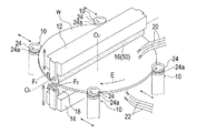
図1は、本発明の基板洗浄方法に使用されるスクラブ洗浄装置の一例を示す概要図である。図1に示すように、このスクラブ洗浄装置は、表面を上にして半導体ウエハ等の基板Wの周縁部を支持し基板Wを水平回転させる、水平方向に移動自在な複数本(図では4本)のスピンドル10と、スピンドル10で支持して回転させる基板Wの上方に昇降自在に配置される上部ロールホルダ12と、スピンドル10で支持して回転させる基板Wの下方に昇降自在に配置される下部ロールホルダ14を備えている。
Embodiments of the present invention will be described below with reference to the drawings.
FIG. 1 is a schematic view showing an example of a scrub cleaning apparatus used in the substrate cleaning method of the present invention. As shown in FIG. 1, this scrub cleaning apparatus supports a peripheral portion of a substrate W such as a semiconductor wafer with its surface facing upward, and horizontally rotates the substrate W (four in the figure are movable in the horizontal direction). ), An
上部ロールホルダ12には、円柱状で長尺状に延びる、例えばPVAからなる上部ロール洗浄部材(ロールスポンジ)16が回転自在に支承されている。下部ロールホルダ14には、円柱状で長尺状に延びる、例えばPVAからなる下部ロール洗浄部材(ロールスポンジ)18が回転自在に支承されている。
An upper roll cleaning member (roll sponge) 16 made of, for example, PVA, is rotatably supported on the
上部ロールホルダ12は、上部ロールホルダ12を昇降させ、上部ロールホルダ12で回転自在に支承した上部ロール洗浄部材16を矢印F1に示すように回転させる、図示しない駆動機構に連結されている。下部ロールホルダ14は、下部ロールホルダ14を昇降させ、下部ロールホルダ14で回転自在に支承した下部ロール洗浄部材18を矢印F2に示すように回転させる、図示しない駆動機構に連結されている。
スピンドル10で支持して回転させる基板Wの上方に位置して、基板Wの表面(上面)に洗浄液を供給する上部洗浄液供給ノズル20が配置され、スピンドル10で支持して回転させる基板Wの下方に位置して、基板Wの裏面(下面)に洗浄液を供給する下部洗浄液供給ノズル22が配置されている。
An upper cleaning
上記構成のスクラブ洗浄装置において、スピンドル10の上部に設けたコマ24の外周側面に形成した嵌合溝24a内に基板Wの周縁部を位置させて内方に押し付けてコマ24を回転(自転)させることにより、基板Wを矢印Eで示すように水平に回転させる。この例では、4個のうち2個のコマ24が基板Wに回転力を与え、他の2個のコマ24は、基板Wの回転を受けるベアリングの働きをしている。なお、全てのコマ24を駆動機構に連結して、基板Wに回転力を付与するようにしてもよい。
In the scrub cleaning apparatus having the above configuration, the peripheral edge of the substrate W is positioned in the
このように基板Wを水平に回転させた状態で、上部洗浄液供給ノズル20から基板Wの表面(上面)に洗浄液(薬液)を供給しつつ、上部ロール洗浄部材16を回転させながら下降させて回転中の基板Wの表面に接触させ、これによって、洗浄液の存在下で、基板Wの表面を上部ロール洗浄部材16でスクラブ洗浄する。上部ロール洗浄部材16の長さは、基板Wの直径より僅かに長く設定されている。そして、上部ロール洗浄部材16は、その中心軸(回転軸)O1が、基板Wの回転軸O2とほぼ直交する位置に位置して、基板Wの直径の全長に亘って延びるように配置され、これによって、基板Wの全表面が同時に洗浄される。
While the substrate W is rotated horizontally in this way, the upper
同時に、下部洗浄液供給ノズル22から基板Wの裏面(下面)に洗浄液を供給しつつ、下部ロール洗浄部材18を回転させながら上昇させて回転中の基板Wの裏面に接触させ、これによって、洗浄液の存在下で、基板Wの裏面を下部ロール洗浄部材18でスクラブ洗浄する。上部ロール洗浄部材16の長さは、基板Wの直径より僅かに長く設定されていて、前述の基板Wの表面とほぼ同様に、基板Wの全裏面が同時に洗浄される。
At the same time, while supplying the cleaning liquid from the lower cleaning
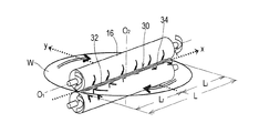
上記のようにして、基板Wの表面を上部ロール洗浄部材(以下、単にロール洗浄部材という)16で洗浄する時、図2に示すように、基板Wとロール洗浄部材16は、ロール洗浄部材16の軸方向に沿って基板Wの直径方向の全長に亘って直線状に延びる、長さLの洗浄エリア30で互いに接触し、この洗浄エリア30に沿った位置で基板Wの表面がスクラブ洗浄される。
When the surface of the substrate W is cleaned with the upper roll cleaning member (hereinafter simply referred to as roll cleaning member) 16 as described above, the substrate W and the
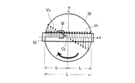
ここに、図3に示すように、基板Wの回転軸O2を中心とした回転に伴う洗浄エリア30に沿った基板の回転速度VWの大きさは、基板Wの回転軸O2上でゼロとなり、回転軸O2を挟んで基板Wの回転速度VWの向き(洗浄方向)が互いに逆となる。一方、ロール洗浄部材16の回転に伴う洗浄エリア30に沿ったロール洗浄部材16の回転速度VRの大きさは、洗浄エリア30の全長に亘って一定で、回転速度VRの向き(洗浄方向)も同じとなる。
Here, as shown in FIG. 3, the magnitude of the rotational velocity V W of the substrate along the
なお、図3は、図2に示すように、洗浄エリア30に沿ってx軸を、基板Wの表面の該x軸に直交する方向にy軸を取り、x−y平面の原点を、基板Wの回転軸O2が通るようにしている。
3, as shown in FIG. 2, the x-axis is taken along the
このため、洗浄エリア30は、基板Wの回転軸O2を挟んで、基板Wの回転速度VWの向きとロール洗浄部材16の回転速度VRの向きが同じとなる、長さLfの順方向洗浄エリア32と、基板Wの回転速度VWの向きとロール洗浄部材16の回転速度VRの向きが互いに逆向きとなる、長さLiの逆方向洗浄エリア34に分けられる。
Therefore, cleaning
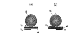
順方向洗浄エリア32では、図4(a)に示すように、基板Wの回転速度VWとロール洗浄部材16の回転速度VRの相対回転速度の大きさが、両者の回転速度の大きさの差の絶対値となって、相対的に低くなる。一方、逆方向洗浄エリア34では、図4(b)に示すように、基板Wの回転速度VWとロール洗浄部材16の回転速度VRの相対回転速度の大きさが、両者の回転速度の大きさの和となって、相対的に高くなる。このため、基板Wの回転速度VWとロール洗浄部材16の回転速度VRの大きさによっては、図3に示すように、両者の相対回転速度の大きさがゼロ(VW=VR)となって、基板Wが洗浄されない領域Mが生じることがある。
In the forward cleaning area 32, as shown in FIG. 4 (a), the rotational speed V W and the rotational speed V magnitude of the relative rotational speed of the R of the
この基板Wが洗浄されない領域Mは、基板Wとロール洗浄部材16とが単に接触しているだけで、基板Wの表面のロール洗浄部材16によるスクラブ洗浄が行われず、逆にロール洗浄部材16に付着した残渣等が基板Wの表面に押し付けられて再付着し、基板Wの表面の汚染の原因となると考えられる。
In the region M where the substrate W is not cleaned, the substrate W and the
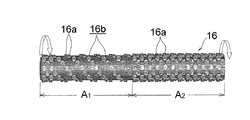
図5は、図1に示すスクラブ洗浄処置に備えられている、本発明の実施形態のロール洗浄部材16を示す正面図である。図5に示すように、ロール洗浄部材16は、表面に多数のノジュール(突起)16aを有しており、このノジュール16aの表面(外端面)を基板Wの表面に接触させて該表面を洗浄するように構成されている。
FIG. 5 is a front view showing the
図2に示すように、ロール洗浄部材16と基板Wの表面とは、長さLの洗浄エリア30で互いに接触するのであるが、ロール洗浄部材16の表面には、多数のノジュール16aが設けられており、このため、洗浄エリア30でロール洗浄部材16に設けられたノジュール16aの表面のみと基板Wの表面とが互いに接触する。そして、長さLの洗浄エリア30は、ロール洗浄部材16と基板Wの相対回転速度が相対的に低い順方向洗浄エリア32(長さLf)と、ロール洗浄部材16と基板Wの相対回転速度が相対的に高い逆方向洗浄エリア34(長さLi)に分けられる。
As shown in FIG. 2, the
そこで、この例では、ロール洗浄部材16を、その長手方向に沿って、順方向洗浄エリアに対応する領域A1と、逆方向洗浄エリアに対応する領域A2の2つの領域に分け、ロール洗浄部材16の順方向洗浄エリアに対応する領域A1の表面に設けられるノジュール16aの分布密度が、逆方向洗浄エリアに対応する領域A2の表面に設けられるノジュール16aの分布密度よりも低くなるようにしている。
Therefore, in this example, the
この例では、ロール洗浄部材16の逆方向洗浄エリアに対応する領域A2の表面に設けられるノジュール16aの分布密度を1(100%)とした時、順方向洗浄エリアに対応する領域A1の表面に設けられるノジュール16aの分布密度が0.5(50%)となるようにしている。このロール洗浄部材16の順方向洗浄エリアに対応する領域A1の表面に設けられるノジュール16aの、逆方向洗浄エリアに対応する領域A2の表面に設けられるノジュール16aに対する分布密度を、洗浄条件等の合わせて任意に設定できることは勿論である。
In this example, when the distribution density of
更に、この例では、ロール洗浄部材16の順方向洗浄エリアに対応する領域A1の表面には、ロール洗浄部材16の回転に伴って、順方向洗浄エリアに存在する洗浄液を基板Wの中心部から外周部に掻き出す方向に螺旋状に連続した螺旋溝16bが長手方向に沿って互いに隣接するノジュール16a間に形成されるように、ノジュール16aが設けられている。
Further, in this example, on the surface of the area A 1 corresponding to the forward cleaning area of the
これにより、基板W上の順方向洗浄エリア32に存在する洗浄液を、ロール洗浄部材16の回転に伴って、洗浄中に基板Wの中心部から外周部に向かってスムーズに移動させて、基板Wの外周部から外部に排出することで、洗浄効率を高めることができる。
As a result, the cleaning liquid existing in the forward cleaning area 32 on the substrate W is smoothly moved from the center of the substrate W toward the outer periphery during the cleaning in accordance with the rotation of the
本発明の基板洗浄方法は、図5に示すロール洗浄部材16を備えた、図1に示すスクラブ洗浄装置を使用し、スピンドル10で水平に保持して回転させた基板Wの表面に、ロール洗浄部材16を回転させながらロール洗浄部材16のノジュール16aを接触させて該表面をスクラブ洗浄する。このスクラブ洗浄時に、基板Wの表面に上部洗浄液供給ノズル20から洗浄液を供給する。このスクラブ洗浄時の概要を図6に示す。
The substrate cleaning method of the present invention uses the scrub cleaning apparatus shown in FIG. 1 provided with the
図6に示すように、基板Wとロール洗浄部材16とが互いに接触する長さLの洗浄エリア30(図2参照)上のロール洗浄部材16と基板Wの相対回転速度が相対的に低い、長さLfの順方向洗浄エリア32(図2参照)では、洗浄エリア30上のロール洗浄部材16と基板Wの相対回転速度が相対的に高い、長さLiの逆方向洗浄エリア34(図2参照)よりも少ない面積で、ロール洗浄部材16に設けたノジュール16aと基板Wの表面とが互いに接触する。
As shown in FIG. 6, the relative rotational speed of the
このように、順方向洗浄エリア32では逆方向洗浄エリア34よりも少ない面積でロール洗浄部材16の表面に設けたノジュール16aと基板Wの表面とを互に接触させることで、逆汚染に伴う洗浄負荷を低減させながら、基板表面の洗浄度を高め、更に洗浄プロセスウェイドウを拡大することができる。
In this way, the
このスクラブ洗浄時に、順方向洗浄エリア32に存在する洗浄液は、ロール洗浄部材16の回転に伴って、ノジュール16a間に形成された螺旋溝16bに沿って、基板Wの中心部から外周部に向けてスムーズに流れて外部に排出される。
During this scrub cleaning, the cleaning liquid present in the forward cleaning area 32 moves from the center of the substrate W toward the outer periphery along the
なお、上記は基板の表面の洗浄について説明しているが、基板の裏面にあっても、基板の表面とほぼ同様に洗浄しても良いことは勿論である。このことは、以下の例においても同様である。 Although the above describes the cleaning of the surface of the substrate, it is needless to say that the cleaning may be performed on the back surface of the substrate in substantially the same manner as the surface of the substrate. The same applies to the following examples.
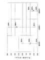
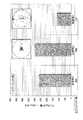
図5に示すロール洗浄部材16を備えた、図1に示すスクラブ洗浄装置を使用して、基板表面を、洗浄条件a,b及びcで洗浄した時の基板表面に残存するディフェクト数を計測した結果を図7に実施例1として示す。
The scrub cleaning apparatus shown in FIG. 1 equipped with the
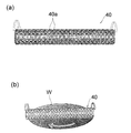
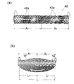
なお、図8(a)に示す、ノジュール40aが全表面にほぼ均等に設けられている従来の一般的なロール洗浄部材40を備えた、図1に示すスクラブ洗浄装置を使用して、基板表面を、実施例1と同じ洗浄条件a,b及びcで洗浄した時の基板表面に残存するディフェクト数を計測した結果を図7に従来例1として示している。図8(b)は、このロール洗浄部材40で基板Wの表面を洗浄している時の概要を示している。
The scrub cleaning apparatus shown in FIG. 1 provided with a conventional general
また、図9(a)に示す、順方向洗浄エリアに対応する領域A2に設けられるノジュール42aの分布密度が、逆方向洗浄エリアに対応する領域A1に設けられるノジュール42aの分布密度よりも低く(この例では50%)なるようにしたロール洗浄部材42を備えた、図1に示すスクラブ洗浄装置を使用して、基板表面を、実施例1と同じ洗浄条件a,b及びcで洗浄した時の基板表面に残存するディフェクト数を計測した結果を図7に比較例1として示している。図9(b)は、このロール洗浄部材42を使用して基板Wの表面を洗浄している時の概要を示している。
Also, shown in FIG. 9 (a), the distribution density of
なお、図7の縦軸は、従来例1において、条件aで基板表面を洗浄した時の基板表面に残存ずるディフェクト数を1.0とした時のディフェクト数の比率(任意単位)を示している。 The vertical axis in FIG. 7 indicates the ratio (arbitrary unit) of the number of defects when the number of defects remaining on the substrate surface when the substrate surface is cleaned under condition a in the conventional example 1 is 1.0. Yes.
図7から、比較例1にあっては、従来例1に比較して、基板表面に残存するディフェクト数が増加しており、このことから、図2に示す逆方向洗浄エリア34で基板とロール洗浄部材の表面に設けられるノジュールとが接触する接触面積を減らすと、洗浄能力が落ちることが判る。そして、実施例1にあっては、比較例1、更には従来例1に比較して、基板表面に残存するディフェクト数が減少しており、このことから、図2に示す順方向洗浄エリア32で基板とロール洗浄部材の表面に設けられるノジュールとが接触する接触面積を減らすことで、高い洗浄度で基板表面を効率的に洗浄して、基板表面に残存するディフェクト数を低減できることが判る。
From FIG. 7, in Comparative Example 1, the number of defects remaining on the surface of the substrate is increased as compared with Conventional Example 1, and from this, the substrate and roll are removed in the
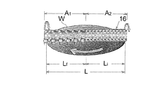
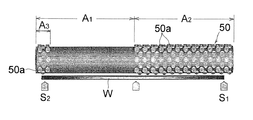
図10は、本発明の他の実施形態のロール洗浄部材50を基板Wと共に示す正面図である。この例のロール洗浄部材50の図5に示すロール洗浄部材16と異なる点は、以下の通りである。つまり、ロール洗浄部材50は、その長手方向に沿って、長さLfの順方向洗浄エリア32(図2参照)に対応する領域A1と、長さLiの逆方向洗浄エリア34(図2参照)に対応する領域A2の2つの領域に分けられている。そして、ロール洗浄部材50の逆方向洗浄エリアに対応する領域A2の表面にはノジュール50aが均等に設けられている。一方、ロール洗浄部材50の順方向洗浄エリアに対応する領域A1には、反逆方向洗浄エリア側端部A3の表面にのみノジュール50aが設けられている。つまり、ロール洗浄部材50の順方向洗浄エリアに対応する領域A1の反逆方向洗浄エリア側端部A3を除く表面にはノジュールが設けられていない。
FIG. 10 is a front view showing a
これにより、ロール洗浄部材50は、ロール洗浄部材50の逆方向洗浄エリアに対応する領域A2の表面に設けられたノジュール50aの表面と、順方向洗浄エリアに対応する領域A1の反逆方向洗浄エリア側端部A3の表面に設けられたノジュール50aの表面のみで基板Wと接触し、あたかも基板Wの直径方向に沿った外周部の支点S1,S2の両端で支持される如く構成されている。
Thus, the
この例のロール洗浄部材50は、例えば、図1に示すスクラブ洗浄装置のロール洗浄部材16の代わりに使用される。そして、このロール洗浄部材50を備えた、図1に示すスクラブ洗浄装置を使用し、スピンドル10で水平に保持して回転させた基板Wの表面に、ロール洗浄部材50を回転させながらロール洗浄部材50のノジュール50aを接触させて該表面をスクラブ洗浄する。このスクラブ洗浄時に、基板Wの表面に上部洗浄液供給ノズル20から洗浄液を供給する。
The
このスクラブ洗浄時に、ロール洗浄部材50の、図2に示す洗浄エリア30上のロール洗浄部材と基板の相対回転速度が相対的に高い逆方向洗浄エリア32に相当する領域A2、及び洗浄エリア30上のロール洗浄部材と基板の相対回転速度が相対的に低い順方向洗浄エリア34に相当する領域A1の反逆方向洗浄エリア側端部A3のみでノジュール50aと基板Wの表面とが互いに接触する。
At the time of scrub cleaning, the area A 2 corresponding to the reverse cleaning area 32 of the
このように、ロール洗浄部材50の順方向洗浄エリアに相当する領域A1の反逆方向洗浄エリア側端部A3以外の領域でロール洗浄部材50と基板Wの表面とが互いに接触しないようにすることで、ロール洗浄部材50の基板Wの表面への接触による逆汚染を防止することができる。しかも、相対回転速度が比較的高い、順方向洗浄エリアに相当する領域A1の反逆方向洗浄エリア側端部A3を洗浄に有効に利用しつつ、ロール洗浄部材50を、基板Wの直径方向に沿った外周部の支点S1,S2で、いわゆる両端支持とすることで、基板Wの中心部に応力集中が生じて洗浄能力が低下してしまうことを回避することができる。
In this way, the
図10に示すロール洗浄部材50を備えた、図1に示すスクラブ洗浄装置を使用して、親水性の基板表面を、所定の洗浄条件で洗浄した時の基板表面に残存するディフェクト数を計測した結果を、基板表面のディフェクトの分布状態と共に、図11に実施例2として示す。
The scrub cleaning apparatus shown in FIG. 1 equipped with the
なお、図8(a)に示す、ノジュール40aが全表面にほぼ均等に設けられている従来の一般的なロール洗浄部材40を備えた、図1に示すスクラブ洗浄装置を使用して、親水性の基板表面を、実施例2と同じ洗浄条件で洗浄した時の基板表面に残存するディフェクト数を計測した結果を図11に従来例2として示している。
In addition, it is hydrophilic using the scrub cleaning apparatus shown in FIG. 1 provided with the conventional general
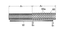
また、図12に示す、逆方向洗浄エリアに対応する領域A2の表面にのみノジュール60aを設け、順方向洗浄エリアに対応する領域A1の表面にノジュールを有さないロール洗浄部材60を備えた、図1に示すスクラブ洗浄装置を使用して、親水性の基板表面を、実施例2と同じ洗浄条件で洗浄した時の基板表面に残存するディフェクト数を計測した結果を、基板表面のディフェクトの分布状態と共に、図11に比較例2として示している。
Also, shown in FIG. 12, the
図11から、比較例2にあっては、従来例2に比較して、洗浄条件によっては、洗浄能力が却って悪くなってしまうことあるばかりでなく、基板表面の中心部にディフェクトが集中して残存することが判る。これは、図12に示すように、ロール洗浄部材60の逆方向洗浄エリアに対応する領域A2は、基板Wの外周部と中心部を支点S1,S3とした、いわゆる両端支持の如く支持されているが、順方向洗浄エリアに対応する領域A1は、基板Wの中心部を支点S3とした、いわゆる片持ち支持の状態となり、この支点S3を通して基板Wの中心部に応力集中が起こるためであると考えられる。
From FIG. 11, in Comparative Example 2, compared with Conventional Example 2, depending on the cleaning conditions, the cleaning ability may be deteriorated, and defects are concentrated at the center of the substrate surface. It can be seen that it remains. As shown in FIG. 12, the region A 2 corresponding to the reverse cleaning area of the
これに対して、実施例2にあっては、前述のように、ロール洗浄部材50は、基板Wの直径方向に沿った外周部の支点S1,S2で、あたかも両端支持の如く支持されており、基板Wの中心部に応力集中が起こらずに、このため、比較例2に比較して、洗浄度を高めることができる。
On the other hand, in the second embodiment, as described above, the
これまで本発明の一実施形態について説明したが、本発明は上述の実施形態に限定されず、その技術的思想の範囲内において種々異なる形態にて実施されてよいことは言うまでもない。 Although one embodiment of the present invention has been described so far, it is needless to say that the present invention is not limited to the above-described embodiment, and may be implemented in various forms within the scope of the technical idea.
10 スピンドル
12 上部ロールホルダ
14 下部ロールホルダ
16 上部ロール洗浄部材(ロールスポンジ)
16a ノジュール
16b 螺旋溝
18 下部ロール洗浄部材(ロールスポンジ)
24 コマ
30 洗浄エリア
32 順方向洗浄エリア
34 逆方向洗浄エリア
Lf 順方向洗浄エリアの長さ
Li 逆方向洗浄エリアの長さ
A1 順方向洗浄エリアに対応する領域
A2 逆方向洗浄エリアに対応する領域
10
24
Claims (6)
前記洗浄エリア上の前記ロール洗浄部材と基板の相対回転速度が相対的に低い順方向洗浄エリアでは、前記洗浄エリア上の前記ロール洗浄部材と基板の相対回転速度が相対的に高い逆方向洗浄エリアよりも少ない面積で前記ノジュールと基板表面とを互いに接触させることを特徴とする基板洗浄方法。 A roll cleaning member that has a large number of nodules on the surface and extends linearly over the entire length of the substrate diameter to form a cleaning area between the substrate surface and the substrate, while rotating the nodule together in one direction. In the substrate cleaning method of scrubbing the surface by bringing the substrate surface and the substrate surface into contact with each other,
In the forward cleaning area where the relative rotational speed of the roll cleaning member and the substrate on the cleaning area is relatively low, the reverse cleaning area where the relative rotational speed of the roll cleaning member and the substrate on the cleaning area is relatively high A substrate cleaning method, wherein the nodule and the substrate surface are brought into contact with each other with a smaller area.
前記洗浄エリア上の前記ロール洗浄部材と基板の相対回転速度が相対的に高い逆方向洗浄エリア、及び前記洗浄エリア上の前記ロール洗浄部材と基板の相対回転速度が相対的に低い順方向洗浄エリアの反逆方向洗浄エリア側端部のみで前記ノジュールと基板表面とを互いに接触させることを特徴とする基板洗浄方法。 A roll cleaning member that has a large number of nodules on the surface and extends linearly over the entire length of the substrate diameter to form a cleaning area between the substrate surface and the substrate, while rotating the nodule together in one direction. In the substrate cleaning method of scrubbing the surface by bringing the substrate surface and the substrate surface into contact with each other,
A reverse cleaning area in which the relative rotational speed of the roll cleaning member and the substrate on the cleaning area is relatively high, and a forward cleaning area in which the relative rotational speed of the roll cleaning member and the substrate on the cleaning area is relatively low. A substrate cleaning method, wherein the nodule and the substrate surface are brought into contact with each other only at the end portion on the side opposite to the reverse cleaning area.
前記洗浄エリア上の基板との相対回転速度が相対的に低い順方向洗浄エリアに対応する領域に設けられる前記ノジュールの分布密度を、前記洗浄エリア上の基板との相対回転速度が相対的に高い逆方向洗浄エリアに対応する領域に設けられる前記ノジュールの分布密度より低くしたことを特徴とするロール洗浄部材。 It has a large number of nodules on the surface, extends linearly over almost the entire length of the diameter of the substrate, forms a cleaning area between the substrate surface, and rotates the nodule and the substrate surface while rotating in one direction together with the substrate. A roll cleaning member that scrubs the surface in contact with each other,
The distribution density of the nodules provided in the region corresponding to the forward cleaning area where the relative rotational speed with the substrate on the cleaning area is relatively low is relatively high with the relative rotational speed with the substrate on the cleaning area. A roll cleaning member, wherein the roll cleaning member has a distribution density lower than that of the nodules provided in a region corresponding to the reverse direction cleaning area.
前記洗浄エリア上の基板との相対回転速度が相対的に高い逆方向洗浄エリアに対応する領域、及び前記洗浄エリア上の基板との相対回転速度が相対的に低い順方向洗浄エリアの反逆方向洗浄エリア側端部に対応する領域のみに前記ノジュールが設けられていることを特徴とするロール洗浄部材。 It has a large number of nodules on the surface, extends linearly over almost the entire length of the substrate, forms a cleaning area with the substrate surface, and rotates the substrate in one direction while rotating the nodule and the substrate surface together. A roll cleaning member for scrubbing the surface by bringing them into contact with each other,
The region corresponding to the reverse cleaning area having a relatively high relative rotational speed with the substrate on the cleaning area, and the reverse cleaning of the forward cleaning area having a relatively low relative rotational speed with the substrate on the cleaning area. The roll cleaning member, wherein the nodule is provided only in a region corresponding to an end portion on the area side.
Priority Applications (4)
| Application Number | Priority Date | Filing Date | Title |
|---|---|---|---|
| JP2011116690A JP5645752B2 (en) | 2011-05-25 | 2011-05-25 | Substrate cleaning method and roll cleaning member |
| US13/478,373 US9011605B2 (en) | 2011-05-25 | 2012-05-23 | Substrate cleaning method and roll cleaning member |
| KR1020120055161A KR101554767B1 (en) | 2011-05-25 | 2012-05-24 | Substrate cleaning method and roll cleaning member |
| TW101118532A TWI512808B (en) | 2011-05-25 | 2012-05-24 | Substrate cleaning method and roller cleaning components |
Applications Claiming Priority (1)
| Application Number | Priority Date | Filing Date | Title |
|---|---|---|---|
| JP2011116690A JP5645752B2 (en) | 2011-05-25 | 2011-05-25 | Substrate cleaning method and roll cleaning member |
Publications (2)
| Publication Number | Publication Date |
|---|---|
| JP2012248564A true JP2012248564A (en) | 2012-12-13 |
| JP5645752B2 JP5645752B2 (en) | 2014-12-24 |
Family
ID=47292094
Family Applications (1)
| Application Number | Title | Priority Date | Filing Date |
|---|---|---|---|
| JP2011116690A Active JP5645752B2 (en) | 2011-05-25 | 2011-05-25 | Substrate cleaning method and roll cleaning member |
Country Status (4)
| Country | Link |
|---|---|
| US (1) | US9011605B2 (en) |
| JP (1) | JP5645752B2 (en) |
| KR (1) | KR101554767B1 (en) |
| TW (1) | TWI512808B (en) |
Cited By (2)
| Publication number | Priority date | Publication date | Assignee | Title |
|---|---|---|---|---|
| KR20150061773A (en) * | 2013-11-28 | 2015-06-05 | 주식회사 케이씨텍 | Substrate cleaning apparatus |
| JP2025065128A (en) * | 2019-09-10 | 2025-04-17 | イリノイ トゥール ワークス インコーポレイティド | Brushes with non-uniform nodule density |
Families Citing this family (7)
| Publication number | Priority date | Publication date | Assignee | Title |
|---|---|---|---|---|
| TW201235155A (en) * | 2011-02-25 | 2012-09-01 | Hon Hai Prec Ind Co Ltd | Cleaning scrap device for grinding plate |
| TWI636518B (en) * | 2013-04-23 | 2018-09-21 | 荏原製作所股份有限公司 | Substrate processing apparatus and method of manufacturing the same |
| CN107078046B (en) * | 2014-10-31 | 2020-11-27 | 株式会社荏原制作所 | Substrate cleaning roller, substrate cleaning device and substrate cleaning method |
| KR102573572B1 (en) * | 2017-12-20 | 2023-09-01 | 삼성전자주식회사 | Wafer cleaning apparatus |
| JP7166132B2 (en) * | 2018-10-12 | 2022-11-07 | 株式会社荏原製作所 | SUBSTRATE CLEANING MEMBER AND SUBSTRATE CLEANING APPARATUS |
| JP2022134658A (en) * | 2021-03-03 | 2022-09-15 | アイオン株式会社 | brush roller |
| WO2025111537A1 (en) * | 2023-11-22 | 2025-05-30 | Tech Core Pva, Llc | Cylindrical brush with varying brush nodule length |
Citations (4)
| Publication number | Priority date | Publication date | Assignee | Title |
|---|---|---|---|---|
| JP2001358110A (en) * | 2000-06-13 | 2001-12-26 | Hitachi Ltd | Scrub cleaning apparatus and semiconductor device manufacturing method using the same |
| JP2002280344A (en) * | 2001-03-16 | 2002-09-27 | Ebara Corp | Substrate processor |
| JP2009066527A (en) * | 2007-09-13 | 2009-04-02 | Nec Electronics Corp | Washing roller and washing apparatus |
| JP2009117765A (en) * | 2007-11-09 | 2009-05-28 | Aion Kk | Sponge roller for cleaning |
Family Cites Families (10)
| Publication number | Priority date | Publication date | Assignee | Title |
|---|---|---|---|---|
| JPH10308374A (en) | 1997-03-06 | 1998-11-17 | Ebara Corp | Method and equipment for cleaning |
| JP2000015190A (en) | 1998-07-03 | 2000-01-18 | Matsushita Electric Ind Co Ltd | Substrate cleaning method and apparatus |
| US6299698B1 (en) * | 1998-07-10 | 2001-10-09 | Applied Materials, Inc. | Wafer edge scrubber and method |
| JP2002043267A (en) | 2000-07-21 | 2002-02-08 | Ebara Corp | Substrate cleaning apparatus, substrate cleaning method, and substrate processing apparatus |
| JP2002313767A (en) | 2001-04-17 | 2002-10-25 | Ebara Corp | Substrate processor |
| US6616516B1 (en) * | 2001-12-13 | 2003-09-09 | Lam Research Corporation | Method and apparatus for asymmetric processing of front side and back side of semiconductor substrates |
| US6733596B1 (en) * | 2002-12-23 | 2004-05-11 | Lam Research Corporation | Substrate cleaning brush preparation sequence, method, and system |
| US20050109371A1 (en) * | 2003-10-27 | 2005-05-26 | Applied Materials, Inc. | Post CMP scrubbing of substrates |
| JP2008282865A (en) | 2007-05-08 | 2008-11-20 | Fuji Electric Device Technology Co Ltd | Scrub cleaning device and roll sponge assembly used therefor |
| TWM362051U (en) * | 2009-02-26 | 2009-08-01 | Tung An Dev Ltd | Structure for cleaning |
-
2011
- 2011-05-25 JP JP2011116690A patent/JP5645752B2/en active Active
-
2012
- 2012-05-23 US US13/478,373 patent/US9011605B2/en active Active
- 2012-05-24 TW TW101118532A patent/TWI512808B/en active
- 2012-05-24 KR KR1020120055161A patent/KR101554767B1/en active Active
Patent Citations (4)
| Publication number | Priority date | Publication date | Assignee | Title |
|---|---|---|---|---|
| JP2001358110A (en) * | 2000-06-13 | 2001-12-26 | Hitachi Ltd | Scrub cleaning apparatus and semiconductor device manufacturing method using the same |
| JP2002280344A (en) * | 2001-03-16 | 2002-09-27 | Ebara Corp | Substrate processor |
| JP2009066527A (en) * | 2007-09-13 | 2009-04-02 | Nec Electronics Corp | Washing roller and washing apparatus |
| JP2009117765A (en) * | 2007-11-09 | 2009-05-28 | Aion Kk | Sponge roller for cleaning |
Cited By (3)
| Publication number | Priority date | Publication date | Assignee | Title |
|---|---|---|---|---|
| KR20150061773A (en) * | 2013-11-28 | 2015-06-05 | 주식회사 케이씨텍 | Substrate cleaning apparatus |
| KR102063464B1 (en) | 2013-11-28 | 2020-01-08 | 주식회사 케이씨텍 | Substrate cleaning apparatus |
| JP2025065128A (en) * | 2019-09-10 | 2025-04-17 | イリノイ トゥール ワークス インコーポレイティド | Brushes with non-uniform nodule density |
Also Published As
| Publication number | Publication date |
|---|---|
| KR20120132380A (en) | 2012-12-05 |
| KR101554767B1 (en) | 2015-09-21 |
| US9011605B2 (en) | 2015-04-21 |
| TW201301373A (en) | 2013-01-01 |
| US20120312323A1 (en) | 2012-12-13 |
| TWI512808B (en) | 2015-12-11 |
| JP5645752B2 (en) | 2014-12-24 |
Similar Documents
| Publication | Publication Date | Title |
|---|---|---|
| JP5645752B2 (en) | Substrate cleaning method and roll cleaning member | |
| JP5886224B2 (en) | Substrate cleaning method | |
| JP5775383B2 (en) | Substrate cleaning method | |
| JP6366544B2 (en) | Cleaning device and roll cleaning member | |
| CN107078046B (en) | Substrate cleaning roller, substrate cleaning device and substrate cleaning method | |
| JP6901277B2 (en) | Scrub cleaning method and scrub cleaning device | |
| TWI590319B (en) | Chemical mechanical polishing and equipment | |
| KR20160052343A (en) | Roll-type processing member, pencil-type processing member, and substrate processing apparatus including any one of these | |
| JP5661564B2 (en) | Cleaning performance prediction method and substrate cleaning method | |
| KR20230047021A (en) | Cleaning apparatus |
Legal Events
| Date | Code | Title | Description |
|---|---|---|---|
| A621 | Written request for application examination |
Free format text: JAPANESE INTERMEDIATE CODE: A621 Effective date: 20130911 |
|
| A977 | Report on retrieval |
Free format text: JAPANESE INTERMEDIATE CODE: A971007 Effective date: 20140709 |
|
| A131 | Notification of reasons for refusal |
Free format text: JAPANESE INTERMEDIATE CODE: A131 Effective date: 20140715 |
|
| A521 | Request for written amendment filed |
Free format text: JAPANESE INTERMEDIATE CODE: A523 Effective date: 20140911 |
|
| TRDD | Decision of grant or rejection written | ||
| A01 | Written decision to grant a patent or to grant a registration (utility model) |
Free format text: JAPANESE INTERMEDIATE CODE: A01 Effective date: 20141014 |
|
| A61 | First payment of annual fees (during grant procedure) |
Free format text: JAPANESE INTERMEDIATE CODE: A61 Effective date: 20141104 |
|
| R150 | Certificate of patent or registration of utility model |
Ref document number: 5645752 Country of ref document: JP Free format text: JAPANESE INTERMEDIATE CODE: R150 |
|
| R250 | Receipt of annual fees |
Free format text: JAPANESE INTERMEDIATE CODE: R250 |
|
| R250 | Receipt of annual fees |
Free format text: JAPANESE INTERMEDIATE CODE: R250 |
|
| R250 | Receipt of annual fees |
Free format text: JAPANESE INTERMEDIATE CODE: R250 |
|
| R250 | Receipt of annual fees |
Free format text: JAPANESE INTERMEDIATE CODE: R250 |
|
| R250 | Receipt of annual fees |
Free format text: JAPANESE INTERMEDIATE CODE: R250 |
|
| R250 | Receipt of annual fees |
Free format text: JAPANESE INTERMEDIATE CODE: R250 |
|
| R250 | Receipt of annual fees |
Free format text: JAPANESE INTERMEDIATE CODE: R250 |
|
| R250 | Receipt of annual fees |
Free format text: JAPANESE INTERMEDIATE CODE: R250 |
|
| R250 | Receipt of annual fees |
Free format text: JAPANESE INTERMEDIATE CODE: R250 |