JP2012248472A - Fuel cell separator plate, fuel cell separator, fuel cell, and manufacturing method of fuel cell separator plate - Google Patents
Fuel cell separator plate, fuel cell separator, fuel cell, and manufacturing method of fuel cell separator plate Download PDFInfo
- Publication number
- JP2012248472A JP2012248472A JP2011120582A JP2011120582A JP2012248472A JP 2012248472 A JP2012248472 A JP 2012248472A JP 2011120582 A JP2011120582 A JP 2011120582A JP 2011120582 A JP2011120582 A JP 2011120582A JP 2012248472 A JP2012248472 A JP 2012248472A
- Authority
- JP
- Japan
- Prior art keywords
- fuel cell
- flow path
- plate
- separator
- electrode body
- Prior art date
- Legal status (The legal status is an assumption and is not a legal conclusion. Google has not performed a legal analysis and makes no representation as to the accuracy of the status listed.)
- Granted
Links
- 239000000446 fuel Substances 0.000 title claims abstract description 77
- 238000004519 manufacturing process Methods 0.000 title claims description 16
- 238000007789 sealing Methods 0.000 claims abstract description 26
- 230000015572 biosynthetic process Effects 0.000 claims abstract description 12
- 239000007789 gas Substances 0.000 claims description 91
- 239000012495 reaction gas Substances 0.000 claims description 23
- 239000002184 metal Substances 0.000 claims description 21
- 229910052751 metal Inorganic materials 0.000 claims description 21
- 238000000465 moulding Methods 0.000 claims description 19
- 239000003507 refrigerant Substances 0.000 claims description 10
- 238000010008 shearing Methods 0.000 claims description 7
- 230000002093 peripheral effect Effects 0.000 claims description 5
- 238000000034 method Methods 0.000 abstract description 23
- 230000001590 oxidative effect Effects 0.000 description 12
- 238000009792 diffusion process Methods 0.000 description 10
- 239000002737 fuel gas Substances 0.000 description 10
- 239000012528 membrane Substances 0.000 description 10
- 239000003054 catalyst Substances 0.000 description 8
- 239000003792 electrolyte Substances 0.000 description 7
- 238000003487 electrochemical reaction Methods 0.000 description 6
- 238000004080 punching Methods 0.000 description 6
- 239000000498 cooling water Substances 0.000 description 5
- 238000005452 bending Methods 0.000 description 4
- 230000000694 effects Effects 0.000 description 4
- 229920001971 elastomer Polymers 0.000 description 4
- OKTJSMMVPCPJKN-UHFFFAOYSA-N Carbon Chemical group [C] OKTJSMMVPCPJKN-UHFFFAOYSA-N 0.000 description 3
- 229910052799 carbon Inorganic materials 0.000 description 3
- 238000007599 discharging Methods 0.000 description 3
- 239000005518 polymer electrolyte Substances 0.000 description 3
- 239000007787 solid Substances 0.000 description 3
- YCKRFDGAMUMZLT-UHFFFAOYSA-N Fluorine atom Chemical compound [F] YCKRFDGAMUMZLT-UHFFFAOYSA-N 0.000 description 2
- UFHFLCQGNIYNRP-UHFFFAOYSA-N Hydrogen Chemical compound [H][H] UFHFLCQGNIYNRP-UHFFFAOYSA-N 0.000 description 2
- 229920005549 butyl rubber Polymers 0.000 description 2
- 238000005553 drilling Methods 0.000 description 2
- 230000005611 electricity Effects 0.000 description 2
- 229910052731 fluorine Inorganic materials 0.000 description 2
- 239000011737 fluorine Substances 0.000 description 2
- 239000001257 hydrogen Substances 0.000 description 2
- 229910052739 hydrogen Inorganic materials 0.000 description 2
- 238000010030 laminating Methods 0.000 description 2
- 239000000463 material Substances 0.000 description 2
- BASFCYQUMIYNBI-UHFFFAOYSA-N platinum Chemical compound [Pt] BASFCYQUMIYNBI-UHFFFAOYSA-N 0.000 description 2
- 238000003825 pressing Methods 0.000 description 2
- 230000002265 prevention Effects 0.000 description 2
- 239000011347 resin Substances 0.000 description 2
- 229920005989 resin Polymers 0.000 description 2
- 238000007086 side reaction Methods 0.000 description 2
- 229920002379 silicone rubber Polymers 0.000 description 2
- 229920000557 Nafion® Polymers 0.000 description 1
- 229910001069 Ti alloy Inorganic materials 0.000 description 1
- RTAQQCXQSZGOHL-UHFFFAOYSA-N Titanium Chemical compound [Ti] RTAQQCXQSZGOHL-UHFFFAOYSA-N 0.000 description 1
- QVGXLLKOCUKJST-UHFFFAOYSA-N atomic oxygen Chemical compound [O] QVGXLLKOCUKJST-UHFFFAOYSA-N 0.000 description 1
- 230000006835 compression Effects 0.000 description 1
- 238000007906 compression Methods 0.000 description 1
- 238000007796 conventional method Methods 0.000 description 1
- 238000001816 cooling Methods 0.000 description 1
- 238000009826 distribution Methods 0.000 description 1
- 239000010411 electrocatalyst Substances 0.000 description 1
- 239000004744 fabric Substances 0.000 description 1
- 239000012530 fluid Substances 0.000 description 1
- 238000005304 joining Methods 0.000 description 1
- 239000007769 metal material Substances 0.000 description 1
- 239000007800 oxidant agent Substances 0.000 description 1
- 239000001301 oxygen Substances 0.000 description 1
- 229910052760 oxygen Inorganic materials 0.000 description 1
- 229910052697 platinum Inorganic materials 0.000 description 1
- 239000002861 polymer material Substances 0.000 description 1
- 230000000630 rising effect Effects 0.000 description 1
- 239000010935 stainless steel Substances 0.000 description 1
- 229910001220 stainless steel Inorganic materials 0.000 description 1
- 239000010409 thin film Substances 0.000 description 1
- 239000010936 titanium Substances 0.000 description 1
- 229910052719 titanium Inorganic materials 0.000 description 1
- XLYOFNOQVPJJNP-UHFFFAOYSA-N water Substances O XLYOFNOQVPJJNP-UHFFFAOYSA-N 0.000 description 1
Images


Classifications
-
- H—ELECTRICITY
- H01—ELECTRIC ELEMENTS
- H01M—PROCESSES OR MEANS, e.g. BATTERIES, FOR THE DIRECT CONVERSION OF CHEMICAL ENERGY INTO ELECTRICAL ENERGY
- H01M8/00—Fuel cells; Manufacture thereof
- H01M8/02—Details
- H01M8/0271—Sealing or supporting means around electrodes, matrices or membranes
-
- H—ELECTRICITY
- H01—ELECTRIC ELEMENTS
- H01M—PROCESSES OR MEANS, e.g. BATTERIES, FOR THE DIRECT CONVERSION OF CHEMICAL ENERGY INTO ELECTRICAL ENERGY
- H01M8/00—Fuel cells; Manufacture thereof
- H01M8/02—Details
- H01M8/0202—Collectors; Separators, e.g. bipolar separators; Interconnectors
- H01M8/0258—Collectors; Separators, e.g. bipolar separators; Interconnectors characterised by the configuration of channels, e.g. by the flow field of the reactant or coolant
-
- H—ELECTRICITY
- H01—ELECTRIC ELEMENTS
- H01M—PROCESSES OR MEANS, e.g. BATTERIES, FOR THE DIRECT CONVERSION OF CHEMICAL ENERGY INTO ELECTRICAL ENERGY
- H01M8/00—Fuel cells; Manufacture thereof
- H01M8/02—Details
- H01M8/0202—Collectors; Separators, e.g. bipolar separators; Interconnectors
- H01M8/0267—Collectors; Separators, e.g. bipolar separators; Interconnectors having heating or cooling means, e.g. heaters or coolant flow channels
-
- H—ELECTRICITY
- H01—ELECTRIC ELEMENTS
- H01M—PROCESSES OR MEANS, e.g. BATTERIES, FOR THE DIRECT CONVERSION OF CHEMICAL ENERGY INTO ELECTRICAL ENERGY
- H01M8/00—Fuel cells; Manufacture thereof
- H01M8/02—Details
- H01M8/0297—Arrangements for joining electrodes, reservoir layers, heat exchange units or bipolar separators to each other
-
- H—ELECTRICITY
- H01—ELECTRIC ELEMENTS
- H01M—PROCESSES OR MEANS, e.g. BATTERIES, FOR THE DIRECT CONVERSION OF CHEMICAL ENERGY INTO ELECTRICAL ENERGY
- H01M8/00—Fuel cells; Manufacture thereof
- H01M8/24—Grouping of fuel cells, e.g. stacking of fuel cells
- H01M8/241—Grouping of fuel cells, e.g. stacking of fuel cells with solid or matrix-supported electrolytes
- H01M8/242—Grouping of fuel cells, e.g. stacking of fuel cells with solid or matrix-supported electrolytes comprising framed electrodes or intermediary frame-like gaskets
-
- H—ELECTRICITY
- H01—ELECTRIC ELEMENTS
- H01M—PROCESSES OR MEANS, e.g. BATTERIES, FOR THE DIRECT CONVERSION OF CHEMICAL ENERGY INTO ELECTRICAL ENERGY
- H01M8/00—Fuel cells; Manufacture thereof
- H01M8/24—Grouping of fuel cells, e.g. stacking of fuel cells
- H01M8/2457—Grouping of fuel cells, e.g. stacking of fuel cells with both reactants being gaseous or vaporised
-
- H—ELECTRICITY
- H01—ELECTRIC ELEMENTS
- H01M—PROCESSES OR MEANS, e.g. BATTERIES, FOR THE DIRECT CONVERSION OF CHEMICAL ENERGY INTO ELECTRICAL ENERGY
- H01M8/00—Fuel cells; Manufacture thereof
- H01M8/24—Grouping of fuel cells, e.g. stacking of fuel cells
- H01M8/2465—Details of groupings of fuel cells
- H01M8/2483—Details of groupings of fuel cells characterised by internal manifolds
-
- H—ELECTRICITY
- H01—ELECTRIC ELEMENTS
- H01M—PROCESSES OR MEANS, e.g. BATTERIES, FOR THE DIRECT CONVERSION OF CHEMICAL ENERGY INTO ELECTRICAL ENERGY
- H01M8/00—Fuel cells; Manufacture thereof
- H01M8/10—Fuel cells with solid electrolytes
- H01M2008/1095—Fuel cells with polymeric electrolytes
-
- Y—GENERAL TAGGING OF NEW TECHNOLOGICAL DEVELOPMENTS; GENERAL TAGGING OF CROSS-SECTIONAL TECHNOLOGIES SPANNING OVER SEVERAL SECTIONS OF THE IPC; TECHNICAL SUBJECTS COVERED BY FORMER USPC CROSS-REFERENCE ART COLLECTIONS [XRACs] AND DIGESTS
- Y02—TECHNOLOGIES OR APPLICATIONS FOR MITIGATION OR ADAPTATION AGAINST CLIMATE CHANGE
- Y02E—REDUCTION OF GREENHOUSE GAS [GHG] EMISSIONS, RELATED TO ENERGY GENERATION, TRANSMISSION OR DISTRIBUTION
- Y02E60/00—Enabling technologies; Technologies with a potential or indirect contribution to GHG emissions mitigation
- Y02E60/30—Hydrogen technology
- Y02E60/50—Fuel cells
-
- Y—GENERAL TAGGING OF NEW TECHNOLOGICAL DEVELOPMENTS; GENERAL TAGGING OF CROSS-SECTIONAL TECHNOLOGIES SPANNING OVER SEVERAL SECTIONS OF THE IPC; TECHNICAL SUBJECTS COVERED BY FORMER USPC CROSS-REFERENCE ART COLLECTIONS [XRACs] AND DIGESTS
- Y02—TECHNOLOGIES OR APPLICATIONS FOR MITIGATION OR ADAPTATION AGAINST CLIMATE CHANGE
- Y02P—CLIMATE CHANGE MITIGATION TECHNOLOGIES IN THE PRODUCTION OR PROCESSING OF GOODS
- Y02P70/00—Climate change mitigation technologies in the production process for final industrial or consumer products
- Y02P70/50—Manufacturing or production processes characterised by the final manufactured product
Abstract
Description
本発明は、燃料電池用セパレータプレート、燃料電池用セパレータ、燃料電池及び燃料電池用セパレータプレートの製造方法に関する。 The present invention relates to a separator plate for a fuel cell, a separator for a fuel cell, a fuel cell, and a method for manufacturing a separator plate for a fuel cell.
固体高分子電解質形燃料電池セルは、イオン透過性の電解質膜と、該電解質膜を挟持するアノード側及びカソード側の触媒層とから膜電極接合体(MEA:Membrane Electrode Assembly)が形成されている。又、前記膜電極接合体に対して燃料ガスもしくは酸化ガスを提供するとともに電気化学反応によって生じた電気を集電するためのアノード側及びカソード側のガス拡散層(GDL:Gas Diffusion Layer)が挟持するように配置されて電極体(MEGA)が形成されている。そして、この電極体を直線状もしくは蛇行状のガス流路を有するセパレータが挟持するように配置されることにより固体高分子電解質形燃料電池セルが構成されている。そして、燃料電池は前記MEGAとセパレータからなる電池セルの積層体を締め付けて一体化したスタックからなる。 In a solid polymer electrolyte fuel cell, a membrane electrode assembly (MEA) is formed from an ion-permeable electrolyte membrane and an anode-side and cathode-side catalyst layer sandwiching the electrolyte membrane. . In addition, a gas diffusion layer (GDL: Gas Diffusion Layer) for supplying fuel gas or oxidizing gas to the membrane electrode assembly and collecting electricity generated by electrochemical reaction is sandwiched. Thus, an electrode body (MEGA) is formed. A solid polymer electrolyte fuel cell is constructed by arranging the electrode body so as to sandwich a separator having a linear or meandering gas flow path. The fuel cell comprises a stack in which the battery cell stack composed of the MEGA and the separator is fastened and integrated.
なお、セパレータには、ガス流路をエキスパンドメタル等の金属多孔体から形成してセパレータから分離させた、いわゆるフラットタイプ型のセパレータもある。
前記セパレータを金属板で構成する場合、前記金属板の中央部に流路溝(或いは突起)などの加工を施すことにより、反応ガスを通すためのガス流路を形成することが多い。
In addition, as the separator, there is also a so-called flat type separator in which a gas flow path is formed from a porous metal such as expanded metal and separated from the separator.
When the separator is made of a metal plate, a gas channel for allowing a reaction gas to pass is often formed by processing a channel groove (or protrusion) or the like at the center of the metal plate.
上記のようにして形成されたセパレータは流路溝(或いは突起)を押し出した分、厚さが大きくなる一方、流路溝の周辺部は板のままである。このため、流路溝を作り出した分に相当する肉厚を有する枠状のシール手段を周辺部に被せて、厚みを調整することが行われている。この場合、セパレータの端部に貫通されて反応ガスを導入又は導出のために設けられたマニホールド孔から流路溝までガスを通すための通路を設けることが必要となる。 The separator formed as described above has a thickness that is increased by pushing out the channel groove (or protrusion), while the peripheral portion of the channel groove remains a plate. For this reason, the thickness is adjusted by covering the peripheral portion with a frame-shaped sealing means having a thickness corresponding to the amount of the flow path groove. In this case, it is necessary to provide a passage for passing the gas from the manifold hole provided for introducing or discharging the reaction gas through the end of the separator.
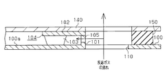
特許文献1では、前記通路の構成及びその製造方法が開示されている。特許文献1の通路について図11、図12を参照して説明する。図11に示すように、金属板からなるセパレータ100には、反応ガス(すなわち、燃料ガス、酸化ガス)及び冷媒を流通させるためのマニホールド孔110,120,130が形成されている。マニホールド孔110の開口周縁部には、セパレータ100のセパレータ表面100aを切り起こして立ち上がり形成したMEGA140(図12参照)の支えとなる支持台104が、セパレータ100の一部として一体的に形成されている。
In patent document 1, the structure of the said channel | path and its manufacturing method are disclosed. The passage of Patent Document 1 will be described with reference to FIGS. 11 and 12. As shown in FIG. 11, the
支持台104は、セパレータ100から垂直に立ち上がる垂直片101と、この垂直片101の先端に水平に設けられる支持片102と、流路108とマニホールド孔110間の流路溝高さを確保すると共にセパレータ表面100aに接して支持台104の支えとなる突部103と、流路108とマニホールド孔110との間を流通する燃料ガス、酸化ガス及び冷媒の流通路となる複数の流通孔105とを有する。前記流通孔105及び支持台104の突部103間がマニホールド孔110から流路108までガスを通すための通路となる。
The
そして、図12に示すように前記支持台104が電極体(MEGA)140の支えとなる。このことにより、電極体140の撓みが防止され、電極体140及びセパレータ100とシール部材150間の密着性が高められて、MEGA140とセパレータ100間のシール部材150のシール性能を向上させる利点がある。
As shown in FIG. 12, the
ところが、特許文献1の場合、上記構成のセパレータは、金属板を単純に打ち抜くだけでは製造できない。すなわち、セパレータ100自身にマニホールド孔110から流路108までのガスを通すための通路を設ける必要があり、そのため、セパレータにガスを通すための通路を形成するために多くの工程が必要となる。具体的には、セパレータのマニホールド孔110の形成予定領域に突部103を形成する工程、マニホールド孔110の形成予定領域に流通孔105を形成する工程、マニホールド孔110の形成予定領域の一辺を残して略コ字状の切り込み孔を入れる工程、マニホールド孔の形成予定領域部分を垂直に立ち上げる工程、その後に行われてマニホールド孔の形成予定領域部分の先端側をマニホールド孔110とは反対側に水平となるように折り曲げる工程が必要となる。
However, in the case of Patent Document 1, the separator configured as described above cannot be manufactured by simply punching a metal plate. That is, it is necessary to provide a passage for passing gas from the
このように、従来、前記支持台は、電極体(MEGA)の撓み防止ができるとともに、電極体及びセパレータとシール部材との間の密着性を高め、シール性能の向上を図ることができるが、一方では支持台にガスを通すための通路を設けるための工程が多く、又、複雑な工程が必要であるため、コスト高となる問題がある。 Thus, conventionally, the support base can prevent the deflection of the electrode body (MEGA) and can improve the adhesion between the electrode body and the separator and the seal member, thereby improving the sealing performance. On the other hand, there are many processes for providing a passage for allowing gas to pass through the support base, and there is a problem that the cost is high because a complicated process is required.
本発明の目的は、上記課題を解決して、電極体(MEGA)の撓み防止のための電極体を支持する構成を備えることにより、電極体及びセパレータとシール部材との間の密着性を高め、シール性能の向上を図ることができるとともに、電極体を支持する構成に対してガスを通すための通路を設けるための工程を従来と比較して大幅に低減でき、コストを抑制できる燃料電池用セパレータプレート、燃料電池用セパレータ、及び燃料電池を提供することにある。 The object of the present invention is to improve the adhesion between the electrode body, the separator and the seal member by providing a structure for supporting the electrode body for preventing the deflection of the electrode body (MEGA) by solving the above-mentioned problems. For fuel cells, which can improve the sealing performance and can significantly reduce the process for providing a passage for passing gas to the structure supporting the electrode body compared to the conventional one, and can suppress the cost. It is providing a separator plate, a separator for fuel cells, and a fuel cell.
又、本発明の他の目的は、電極体及びセパレータとシール部材との間の密着性を高め、シール性能の向上を図ることができるとともに、電極体を支持する構成にガスを通すための通路を設けるための工程を従来と比較して大幅に低減でき、コストを抑制できる燃料電池用セパレータプレートの製造方法を提供することにある。 Another object of the present invention is to increase the adhesion between the electrode body and the separator and the seal member, improve the sealing performance, and pass the gas through the structure supporting the electrode body. It is an object of the present invention to provide a method of manufacturing a separator plate for a fuel cell, which can significantly reduce the steps for providing the fuel cell and can reduce the cost.
上記問題点を解決するために、請求項1の発明は、燃料電池に使用される反応ガス及び冷媒を流通させる各流路と、前記各流路に前記反応ガス及び冷媒を流通させるためのマニホールド孔を備えた金属製の燃料電池用セパレータプレートにおいて、前記マニホールド孔と前記流路との間には、前記各流路が形成された流路形成領域よりも高く形成されて膨出するとともに燃料電池の電極体を支持する膨出部が形成され、前記膨出部の前記流路側の側面には、前記マニホールド孔と前記流路に連通するガス流通孔が形成されていることを特徴とする燃料電池用セパレータプレートを要旨としている。 In order to solve the above-described problems, the invention of claim 1 includes a flow path for flowing a reaction gas and a refrigerant used in a fuel cell, and a manifold for flowing the reaction gas and the refrigerant through each flow path. In a metal fuel cell separator plate having holes, a fuel plate is formed between the manifold hole and the flow path so as to be higher than a flow path forming region in which the flow paths are formed and swell. A bulging portion for supporting an electrode body of the battery is formed, and a gas flow hole communicating with the manifold hole and the flow channel is formed on a side surface of the bulging portion on the flow path side. The gist is a separator plate for a fuel cell.
請求項1の燃料電池用セパレータプレートは、マニホールド孔と流路との間に、流路形成領域よりも高く形成された膨出部により電極体を支持し、電極体(MEGA)の撓み防止が図られる。このため、電極体・セパレータ間に配置されたシール部材と、電極体及びセパレータのそれぞれの間の密着性が高められ、シール性能の向上が図ることができる。又、膨出部の形成は、プレス成形により簡単に行えるとともに、ガスを通すための通路を設けるための工程が従来と比較して大幅に低減できる。 The separator plate for a fuel cell according to claim 1 supports the electrode body by a bulging portion formed higher than the flow path formation region between the manifold hole and the flow path, and prevents the deflection of the electrode body (MEGA). Figured. For this reason, the adhesion between the seal member disposed between the electrode body / separator and each of the electrode body and the separator is enhanced, and the sealing performance can be improved. In addition, the formation of the bulging portion can be easily performed by press molding, and the process for providing a passage for passing gas can be significantly reduced as compared with the conventional case.
請求項2の発明は、請求項1において、前記ガス流通孔は、前記膨出部が膨出加工された際の剪断により形成されていることを特徴とする。
請求項2の燃料電池用セパレータプレートのガス流通孔は、膨出加工された際の剪断により、簡単に形成され、セパレータプレートの加工が容易となる。
The invention of
The gas flow holes of the separator plate for a fuel cell according to
請求項3の発明は、請求項1又は請求項2において、平板部を備え、前記平板部には、前記マニホールド孔が形成されるとともに前記流路が形成され、前記膨出部は、前記平板部から膨出形成されていることを特徴とする。 According to a third aspect of the present invention, the flat plate portion according to the first or second aspect includes the flat plate portion, the manifold hole is formed in the flat plate portion, the flow path is formed, and the bulge portion is formed of the flat plate portion. It is characterized by bulging from the part.
請求項3では、平板部から膨出形成された膨出部を有する燃料電池用セパレータプレートにおいて、請求項1又は請求項2の作用を容易に実現する。
請求項4の発明は、請求項1又は請求項2において、凹状に形成された中央部と、前記中央部の周囲を囲む額縁部が前記中央部の周縁から膨出形成され、前記中央部が流路形成領域として前記流路を備え、前記額縁部に、前記マニホールド孔が形成され、前記マニホールド孔に隣接する前記額縁部の一部が前記膨出部とされ、前記膨出部の流路側の側面には、前記マニホールド孔と前記流路に連通するガス流通孔が形成されていることを特徴とする。
According to the third aspect of the present invention, the operation of the first or second aspect can be easily realized in the separator plate for a fuel cell having the bulging portion formed by bulging from the flat plate portion.
According to a fourth aspect of the present invention, in the first or second aspect, a concave central portion and a frame portion surrounding the periphery of the central portion bulge out from the periphery of the central portion, and the central portion is The flow path forming region includes the flow path, the manifold hole is formed in the frame portion, a part of the frame portion adjacent to the manifold hole is the bulge portion, and the flow channel side of the bulge portion A gas flow hole communicating with the manifold hole and the flow path is formed on the side surface of the gas.
請求項4では、額縁部にマニホールド孔を有するとともに、マニホールド孔に隣接する額縁部の一部が膨出部としている燃料電池用セパレータプレートにおいて、請求項1又は請求項2の作用を容易に実現する。 According to a fourth aspect of the present invention, the operation of the first or second aspect can be easily realized in a fuel cell separator plate having a manifold hole in the frame portion and a part of the frame portion adjacent to the manifold hole being a bulging portion. To do.
請求項5の発明は、請求項1乃至請求項4のいずれか1項に記載の燃料電池用セパレータプレートを第1セパレータプレートとし、第1セパレータプレートに対して枠状のシール手段を介して前記膨出部が支持する電極体とは反対側において第2セパレータプレートとが積層された燃料電池用セパレータであって、前記第1セパレータ又は第2セパレータプレートのいずれか一方のセパレータプレートには、前記膨出部の前記電極体の反対側から前記膨出部を支持する支持手段が他方のセパレータプレートまで延出形成されていることを特徴とする燃料電池用セパレータを要旨としている。 According to a fifth aspect of the present invention, the separator plate for a fuel cell according to any one of the first to fourth aspects is used as a first separator plate, and the first separator plate is provided with a frame-like sealing means via the frame-like sealing means. A separator for a fuel cell in which a second separator plate is laminated on the side opposite to the electrode body supported by the bulging portion, and the separator plate of either the first separator or the second separator plate includes The gist of the fuel cell separator is characterized in that a support means for supporting the bulging portion extends from the opposite side of the bulging portion to the electrode body to the other separator plate.
請求項5の燃料電池用セパレータの一方のセパレータプレートから他方のセパレータプレートに支持手段が延出形成されていることにより、膨出部とともに電極体を支持し、電極体(MEGA)の撓み防止が図られる。このため、電極体・第1セパレータプレート間に配置されたシール部材と、電極体及び第1セパレータプレートのそれぞれの間の密着性が高められ、シール性能の向上が図ることができる。又、第1セパレータプレートの膨出部の形成は、プレス成形により簡単に行えるとともに、ガスを通すための通路を設けるための工程が従来と比較して大幅に低減できる。 The support means is formed so as to extend from one separator plate of the fuel cell separator to the other separator plate, thereby supporting the electrode body together with the bulging portion and preventing the electrode body (MEGA) from being bent. Figured. For this reason, the adhesion between the seal member disposed between the electrode body and the first separator plate and each of the electrode body and the first separator plate is enhanced, and the sealing performance can be improved. Further, the formation of the bulging portion of the first separator plate can be easily performed by press molding, and the process for providing a passage for passing gas can be greatly reduced as compared with the conventional case.
請求項6の発明は、請求項5に記載の燃料電池用セパレータと前記電極体とが交互に積層されていることを特徴とする燃料電池を要旨としている。
請求項6の発明の構成により、請求項5の作用を容易に実現できる燃料電池が得られる。
The gist of a sixth aspect of the invention is a fuel cell characterized in that the fuel cell separator according to the fifth aspect and the electrode body are alternately laminated.
According to the configuration of the invention of claim 6, a fuel cell capable of easily realizing the operation of claim 5 is obtained.
請求項7の発明は、燃料電池に使用される反応ガス及び冷媒を流通させる各流路と、前記各流路に前記反応ガス及び冷媒を流通させるためのマニホールド孔を備えた金属製の燃料電池用セパレータプレートの製造方法であって、金属板の前記マニホールド孔と前記流路間の領域に対して、燃料電池の電極体を支持する膨出部を、前記各流路が形成された又は流路が形成される流路形成領域よりも高くなるようにプレス成形で膨出するとともに、前記プレス成形時に、前記膨出部の前記流路側の側面に、前記マニホールド孔と前記流路に連通されるガス流通孔を形成することを特徴とする燃料電池用セパレータプレートの製造方法を要旨としている。 The invention according to claim 7 is a metal fuel cell comprising each flow path for flowing a reaction gas and a refrigerant used in a fuel cell, and a manifold hole for flowing the reaction gas and the refrigerant in each flow path. A separator plate manufacturing method, wherein a bulging portion that supports an electrode body of a fuel cell is formed in a region between the manifold hole and the flow path of a metal plate, and each flow path is formed or flowed. The bulge is formed by press molding so as to be higher than the flow path forming region where the path is formed, and at the time of the press molding, the side surface of the bulging portion on the flow path side is communicated with the manifold hole and the flow path. The present invention is summarized as a method for producing a separator plate for a fuel cell, characterized in that a gas flow hole is formed.
請求項7の発明の構成により、金属板の前記マニホールド孔と前記流路間の領域に対して、燃料電池の電極体を支持する膨出部を、前記各流路が形成された又は流路が形成される流路形成領域よりも高くなるようにプレス成形で膨出するだけで、膨出部が得られる。そして、膨出部のプレス成形時に、マニホールド孔と前記流路に連通されるガス流通孔が形成される。 According to the configuration of the invention of claim 7, the bulging portion that supports the electrode body of the fuel cell is formed in the region between the manifold hole and the flow path of the metal plate, or each flow path is formed. The swollen portion is obtained simply by swollen by press molding so as to be higher than the flow path forming region in which is formed. And the gas distribution hole connected to a manifold hole and the said flow path is formed at the time of press molding of the bulging portion.
請求項1の発明によれば、電極体(MEGA)の撓み防止のための電極体を支持する構成を備えることにより、電極体及びセパレータとシール部材との間の密着性を高め、シール性能の向上を図ることができるとともに、電極体を支持する構成に対してガスを通すための通路を設けるための工程を従来と比較して大幅に低減でき、コストを抑制できる燃料電池用セパレータプレートを提供できる。 According to the first aspect of the invention, by providing a structure for supporting the electrode body (MEGA) for preventing the deflection of the electrode body (MEGA), the adhesion between the electrode body and the separator and the seal member is improved, and the sealing performance is improved. Providing a separator plate for a fuel cell that can be improved and can significantly reduce the process for providing a gas passage for the structure that supports the electrode body as compared to the conventional method, thereby reducing costs. it can.
請求項2の発明によれば、膨出部の膨出加工時に、ガス流通孔が剪断により、簡単に形成すればよいため、セパレータプレートの加工を容易にすることができる。
請求項3の発明によれば、平板部から膨出形成された膨出部を有する燃料電池用セパレータプレートにおいて、請求項1又は請求項2の効果を容易に実現できる。
According to the second aspect of the present invention, since the gas flow hole may be simply formed by shearing at the time of the bulging process of the bulging portion, the processing of the separator plate can be facilitated.
According to the invention of claim 3, the effect of claim 1 or
請求項4の発明によれば、額縁部にマニホールド孔を有するとともに、マニホールド孔に隣接する額縁部の一部が膨出部としている燃料電池用セパレータプレートにおいて、請求項1又は請求項2の効果を容易に実現できる。
According to the invention of claim 4, in the separator plate for a fuel cell, which has a manifold hole in the frame portion and a part of the frame portion adjacent to the manifold hole is a bulging portion, the effect of claim 1 or
請求項5の発明によれば、電極体(MEGA)の撓み防止のための電極体を支持する構成を備えることにより、電極体及びセパレータとシール部材との間の密着性を高め、シール性能の向上を図ることができるとともに、電極体を支持する構成に対してガスを通すための通路を設けるための工程を従来と比較して大幅に低減でき、コストを抑制できる燃料電池用セパレータ組立体を提供することにある。 According to invention of Claim 5, by providing the structure which supports the electrode body for the bending prevention of an electrode body (MEGA), the adhesiveness between an electrode body and a separator, and a sealing member is improved, and sealing performance is improved. A separator assembly for a fuel cell that can be improved and can significantly reduce the process for providing a passage for passing gas to the configuration that supports the electrode body compared to the conventional one, and can suppress the cost. It is to provide.
請求項6の発明によれば、電極体(MEGA)の撓み防止のための電極体を支持する構成を備えることにより、電極体及びセパレータとシール部材との間の密着性を高め、シール性能の向上を図ることができるとともに、電極体を支持する構成に対してガスを通すための通路を設けるための工程を従来と比較して大幅に低減でき、コストを抑制できる燃料電池を提供できる。 According to invention of Claim 6, by providing the structure which supports the electrode body for bending prevention of an electrode body (MEGA), the adhesiveness between an electrode body and a separator, and a sealing member is improved, and sealing performance is improved. It is possible to provide a fuel cell that can be improved, and that a process for providing a passage for allowing gas to pass through the configuration that supports the electrode body can be significantly reduced as compared with the conventional case, and the cost can be suppressed.
請求項7の発明によれば、電極体及びセパレータプレートとシール部材との間の密着性を高め、シール性能の向上を図ることができるとともに、電極体を支持する構成にガスを通すための通路を設けるための工程を従来と比較して大幅に低減でき、コストを抑制できる燃料電池用セパレータプレートの製造方法を提供できる。 According to the seventh aspect of the present invention, it is possible to improve the adhesion between the electrode body and the separator plate and the seal member, to improve the sealing performance, and to pass the gas through the structure that supports the electrode body. The manufacturing method of the separator plate for fuel cells which can reduce significantly the process for providing this compared with the past, and can suppress cost can be provided.
(第1実施形態)
以下、本発明の燃料電池、燃料電池用セパレータ、燃料電池用セパレータ組立体を具体化した第1実施形態の燃料電池を図1〜図4を参照して説明する。
(First embodiment)
A fuel cell according to a first embodiment that embodies a fuel cell, a fuel cell separator, and a fuel cell separator assembly according to the present invention will be described below with reference to FIGS.
本実施形態では、セパレータ30を構成しているアノードプレート34に膨出部が設けられるとともに、カソードプレート35に支持手段が設けられたものである。
図1に示す本実施形態の燃料電池10は、水素を含有する燃料ガスと酸素を含有する酸化ガスとの供給を受け、燃料ガスと酸化ガス(以下、必要に応じてまとめて反応ガスと呼ぶ)との電気化学反応により発電する固体高分子型の燃料電池である。
In this embodiment, the
A fuel cell 10 of the present embodiment shown in FIG. 1 is supplied with a fuel gas containing hydrogen and an oxidizing gas containing oxygen, and referred to as a fuel gas and an oxidizing gas (hereinafter collectively referred to as a reactive gas as necessary). ) And a polymer electrolyte fuel cell that generates electric power through an electrochemical reaction.
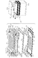
図1に示すように、燃料電池10は、燃料電池セル20が複数積層され、その両端から図示しない一対のエンドプレート80A,80Bにより狭持されている。エンドプレート80Aには、反応ガス等を供給あるいは排出する図示しない貫通孔が形成されており、この貫通孔を介して図示しない外部の水素タンクやコンプレッサ等から、燃料電池10の内部に反応ガスが滞りなく供給される。
As shown in FIG. 1, the fuel cell 10 includes a plurality of stacked
図1、図3に示すように、燃料電池セル20は、電極体(MEGA)21、及び枠状のシールガスケット31,32を介して電極体21を挟むように位置する一対のセパレータ30を備える。
As shown in FIGS. 1 and 3, the
図3に示すように、電極体21は、図示はしないが膜電極接合体(MEA:Membrane Electrode Assembly)と、該MEAの両側面に設けられたガス拡散層を備える。又、MEAは、イオン透過性の電解質膜と、該電解質膜を挟持するアノード側及びカソード側の電極触媒層とからなる。本実施形態では、電極体21は、図1に示すように略長方形状に形成されている。
As shown in FIG. 3, the
前記電解質膜は、プロトン伝導性を備え、湿潤状態で良好な電気伝導性を示す固体高分子材料の薄膜である。電解質膜としては、例えば、ナフィオンを挙げることができる。電解質膜の表面上に形成されたアノード側電極触媒層,カソード側電極触媒層は、電気化学反応を促進する触媒、例えば、白金が担持されている。 The electrolyte membrane is a solid polymer material thin film having proton conductivity and good electrical conductivity in a wet state. Examples of the electrolyte membrane include Nafion. The anode side electrode catalyst layer and the cathode side electrode catalyst layer formed on the surface of the electrolyte membrane carry a catalyst that promotes an electrochemical reaction, for example, platinum.
前記ガス拡散層は、カーボン製の多孔体であり、例えば、カーボンクロスやカーボンペーパによって形成されている。ガス拡散層は、接合によりMEAのアノード側側面及びカソード側側面と一体化されて電極体21となる。
The gas diffusion layer is a carbon porous body, and is formed of, for example, carbon cloth or carbon paper. The gas diffusion layer is integrated with the anode side surface and the cathode side surface of the MEA by bonding to form the
アノード側のガス拡散層は、アノード側の反応ガス(すなわち、燃料ガス)をその厚み方向に拡散して、アノード側電極触媒層の全面に供給する。カソード側のガス拡散層は、カソード側の反応ガス(すなわち、酸化ガス)をその厚み方向に拡散して、カソード側電極触媒層の全面に供給する。 The anode-side gas diffusion layer diffuses the anode-side reaction gas (that is, fuel gas) in the thickness direction and supplies it to the entire surface of the anode-side electrode catalyst layer. The cathode-side gas diffusion layer diffuses the cathode-side reaction gas (that is, oxidizing gas) in the thickness direction and supplies it to the entire surface of the cathode-side electrode catalyst layer.
前記シールガスケット31,32の枠部31a,32aが、電極体21の両側面の周縁に沿って配置されることにより、電極体21とセパレータ30との間に、反応ガスが流れる空間が形成されている。
Since the
シールガスケット31,32は、シリコンゴム、ブチルゴム、フッ素ゴムなど、弾性を有するゴム製の絶縁性樹脂材料からなる。シールガスケット31,32は、セパレータ30と同様の大きさの略長方形に形成されている。図1に示すように、シールガスケット31,32の長手方向の両端側には、前記各流路に連通するとともに反応ガス及び冷却水のマニホールドを形成する貫通孔が設けられている。シールガスケット32は、シール部材に相当する。
The seal gaskets 31 and 32 are made of an insulating resin material made of rubber having elasticity, such as silicon rubber, butyl rubber, and fluorine rubber. The seal gaskets 31 and 32 are formed in a substantially rectangular shape having the same size as the
又、電極体21においても、長手方向の両端側には、前記各流路に連通するとともに反応ガス及び冷却水のマニホールドを形成する貫通孔が設けられている。
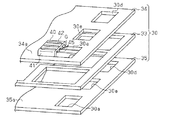
次に電気化学反応により生ずる電気を集電するセパレータ30について説明する。セパレータ30は、金属の薄板(金属板)からなるアノード側に配置されるアノードプレート34と、カソード側に配置されるカソードプレート35が、シール部材としてのシールガスケット33を介して積層されて構成されている。シールガスケット33はシール手段に相当する。
Also in the
Next, the
アノードプレート34,及びカソードプレート35は、例えば、ステンレス鋼やチタン,チタン合金など、導電性の金属材料から構成されている。
アノードプレート34は第1セパレータプレートに相当し、カソードプレート35は第2セパレータプレートに相当する。
The
The
アノードプレート34は、略長方形状に形成された平坦な平板部34aからなる。平板部34aの中央部には複数の突部からなる流路(或いは断面が波形に形成された流路)37が形成されて、該流路37により、電極体21のアノード側のガス拡散層を介してアノード側電極触媒層と接触する。流路37は、図1に示すようにシールガスケット32の枠部32aにより囲われており、電極体21とセパレータ30との間の反応ガスが流れる空間内に位置する。流路37が形成された領域は、流路形成領域に相当する。
The
又、カソードプレート35は、略長方形に形成された平坦な平板部35aからなる。平板部35aの中央部には複数の突部からなる流路(或いは断面が波形に形成された流路)38が形成されて、該流路38により、電極体21のアノード側のガス拡散層を介してカソード側電極触媒層と接触する。なお、図1では説明の便宜上、流路38の符号の引き出し線は、流路が形成された部分の裏側(図面上では上側)を指している。
The
前記流路38は、シールガスケット31の枠部31aにより囲われており、電極体21とセパレータ30との間の反ガスが流れる空間内に位置する。
アノードプレート34と、カソードプレート35の間はシールガスケット33が挟まれ、シールガスケット33と両プレート間で形成される空間に位置するように前記流路37,38の裏側の形状によって、主に冷却水の流路が設けられている。
The
A
アノードプレート34、及びカソードプレート35の平板部34a,35aには、マニホールド孔が貫通形成されている。
具体的には、図1に示すように、各プレート34,35の両短辺側にはそれぞれ燃料ガス供給用のマニホールド孔30a、燃料ガス排出用のマニホールド孔30bが設けられている。又、各プレート34,35の両短辺側にはそれぞれ酸化ガス供給用のマニホールド孔30c、酸化ガス排出用のマニホールド孔30dが設けられている。又、各プレート34,35の両短辺側において、マニホールド孔30a,30d間、及びマニホールド孔30b,30c間には、冷却水供給用のマニホールド孔30e及び冷却水排出用のマニホールド孔30fが、それぞれ設けられている。
Manifold holes are formed through the
Specifically, as shown in FIG. 1, a fuel gas
なお、説明の便宜上、図1では、アノードプレート34のマニホールド孔30a〜30fは全部図示しているが、カソードプレート35のマニホールド孔の中で、マニホールド孔30bのみは、隠れているため図示されていない。
For convenience of explanation, FIG. 1 shows all the manifold holes 30 a to 30 f of the
シールガスケット33は、シリコンゴム、ブチルゴム、フッ素ゴムなど、弾性を有するゴム製の絶縁性樹脂材料からなる。シールガスケット33は、アノードプレート34,及びカソードプレート35と略同じ大きさであって、略長方形に形成されている。図1に示すように、シールガスケット33の長手方向の両端側には、前記各流路に連通するとともに反応ガス及び冷却水のマニホールドを形成する貫通孔が設けられている。
The
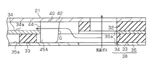
アノードプレート34のマニホールド孔30a,30bにおいて、流路37側には、平板部34aからアノード側に流路形成領域の高さよりも高くなるように膨出形成された膨出部としての支持部40が設けられている。なお、流路37が形成された領域は、流路形成領域に相当する。支持部40は、平板部34aに連結された一対の脚部41と、脚部41の先端間を連結する頂部42とからなる。支持部40の断面形状は、限定するものではないが、好ましくは、頂部42のアノード側の表面は平坦面を有することが好ましい。支持部40は、平板部34aから膨出成形される際に、流路37側が剪断されて、図3に示すように平板部34aとの間らガス流通孔44が形成されている。
In the
そして、両支持部40は、頂部42が電極体21のアノード側側面に当接することにより、電極体21を支持している。
一方、カソードプレート35において、前記支持部40に相対した部位の平板部35aには、平板部35aからアノード側に突出形成された支持手段としての単数又は複数の柱部43が設けられている。柱部43は、図3に示すように、平板部35aのカソード側からアノード側へプレス成型されて袋状に形成されるとともに、支持部40側に延出形成されたものである。
The two
On the other hand, in the
柱部43の先端面は平坦に形成されて、支持部40の内面に当接されている。各柱部43は、短辺に沿って並ぶように配置され、柱部43間及び柱部43と脚部41間は、マニホールド孔30aと、アノードプレート34の流路37間を流れる反応ガスのガス流路Gとなっている。柱部43の先端面は平坦面を有することが好ましい。
The front end surface of the
そして、各柱部43は、頂部42の内面に当接することにより、支持部40を支持し、支持部40の電極体21の支持をサポートしている。
なお、図1に示すカソードプレート35のマニホールド孔30bの近位の部位には、アノードプレート34のマニホールド孔30bの支持部40を支持する単数又は複数の柱部43(図示はしない)が、マニホールド孔30aに近位に設けられた柱部43と同様に設けられている。
Each
A single or a plurality of column parts 43 (not shown) that support the
さらに、図4に示すように、カソードプレート35のマニホールド孔30cにおいて、流路37側には、平板部35aからカソード側に流路形成領域の高さよりも高くなるように膨出形成された膨出部としての支持部40Aが設けられている。支持部40Aは、平板部35aに連結された一対の脚部41Aと、脚部41Aの先端間を連結する頂部42Aとからなる。支持部40Aの断面形状は、支持部40と同様に限定するものではないが、好ましくは、頂部42Aのアノード側の表面は平坦面を有することが好ましい。支持部40Aは、平板部35aから膨出成形される際に、流路37側が剪断されて、図4に示すように平板部35aとの間に流通孔44Aが形成されている。
Further, as shown in FIG. 4, in the
そして、両支持部40Aは、頂部42Aが電極体21のカソード側側面に当接することにより、電極体21を支持している。
なお、図4では、マニホールド孔30c側を図示しているが、カソードプレート35のマニホールド孔30dにおいても、図示はしないが同様に支持部40Aが形成されている。
Both
Although FIG. 4 shows the
一方、図4に示すようにアノードプレート34において、前記支持部40Aに相対した部位の平板部34aには、平板部34aからカソード側に突出形成された支持手段としての単数又は複数の柱部43Aが設けられている。柱部43Aは、図4に示すように、平板部34aのアノード側からカソード側へプレス成型されて袋状に形成されるとともに、支持部40A側に延出形成されたものである。
On the other hand, as shown in FIG. 4, in the
柱部43Aの先端面は平坦に形成されて、支持部40Aの内面に当接されている。各柱部43Aは、短辺に沿って並ぶように配置され、柱部43A間及び柱部43Aと脚部41A間は、マニホールド孔30cと、カソードプレート35の流路間を流れる酸化ガスのガス流路GAとなっている。柱部43Aの先端面は平坦面を有することが好ましい。
The front end surface of the
そして、各柱部43Aは、頂部42Aの内面に当接することにより、支持部40Aを支持し、支持部40Aの電極体21の支持をサポートしている。
なお、アノードプレート34のマニホールド孔30dの近位の部位には、カソードプレート35のマニホールド孔30dの支持部40Aを支持する単数又は複数の柱部43A(図示はしない)が、マニホールド孔30cに近位に設けられた柱部43Aと同様に、設けられている。 (アノードプレート34、カソードプレート35の製造方法について)
ここで、アノードプレート34及びカソードプレート35の製造方法について説明する。
And each
In addition, at a portion proximal to the
Here, a manufacturing method of the
金属板に対して、マニホールド孔30a〜30f、流路37のプレス成形と同時に支持部40、40Aを金型にプレス加工する。
このプレス成形時において、金型によりマニホールド孔30a〜30fを抜き加工する。この抜き加工の際に、マニホールド孔30aと流路37間の領域、マニホールド孔30bと流路37間の領域、マニホールド孔30cと流路37間の領域、及びマニホールド孔30dと流路37間の領域に対応した部位(すなわち、支持部40,40Aとなる領域)に対して、マニホールド孔30a〜30fの抜き加工後も、金型により、曲げ成形して膨出させる。支持部40,40Aが平板部34aからトンネル状に膨出形成される際、支持部40,40Aの流路37が剪断されてガス流通孔44,44Aが形成される。
The
At the time of the press molding, the
又、前記抜き加工と同時、或いは後の工程において柱部43,43Aをプレス成形により曲げ加工する。 こうして形成されたアノードプレート34及びカソードプレート35を積層して接合することにより、セパレータ30の内部には各種流体の流路が形成される。
In addition, the
(実施形態の作用)
次に、本実施形態の作用を説明する。
図3に示すように、セパレータ30及びシールガスケット31,32の積層により形成されるマニホールド(マニホールド孔を含む)内を流れる燃料ガスの一部は、カソードプレート35のマニホールド孔30aを通ってガス流路Gへ供給される。そして、ガス流路Gに流れた反応ガス(本実施形態では燃料ガス)は、ガス流通孔44を介して流路37に流れて、電極体21での電気化学反応に供される。
(Operation of the embodiment)
Next, the operation of this embodiment will be described.
As shown in FIG. 3, a part of the fuel gas flowing in the manifold (including the manifold hole) formed by stacking the
又、流路37を通過した反応ガスは、図示しないもう一方の支持部のガス流通孔、ガス流通路を介して、マニホールド孔30bへ導出される。
又、セパレータ30及びシールガスケット31,32の積層により形成されるマニホールド(マニホールド孔を含む)内を流れる酸化ガスの一部は、カソードプレート35のマニホールド孔30cを通ってガス流路GAへ供給される。そして、ガス流路GAに流れた酸化ガスは、ガス流通孔44Aを介して流路37に流れて、電極体21での電気化学反応に供される。
Further, the reaction gas that has passed through the
Part of the oxidizing gas flowing in the manifold (including the manifold hole) formed by stacking the
又、流路37を通過した酸化ガスは、図示しないもう一方の支持部のガス流通孔、ガス流通路を介して、マニホールド孔30dへ導出される。 又、本実施形態では、電極体21は、アノードプレート34の支持部40,40A及び柱部43,43Aにより支持されて撓みが防止され、電極体21を保持することができる。このため、電極体21及びセパレータ30とシールガスケット32(シール部材)との間の密着性を高め、シール性能の向上を図ることができる。
The oxidizing gas that has passed through the
又、本実施形態のアノードプレート34の支持部40,40Aを、複雑な工程を経ることなくプレス加工により容易に得ることができるとともに、ガス流路G,GAの形成において、プレス加工の際に、剪断によりガス流路Gが形成されるため、特別な穴開け工程が必要でなくなる。
In addition, the
本実施形態では、下記の特徴を有する。
(1) 本実施形態のアノードプレート34及びカソードプレート35は、マニホールド孔30a(30b)と流路37との間及びマニホールド孔30c(30d)と流路37との間には、流路37が形成された流路形成領域よりも高く形成されて膨出するとともに燃料電池の電極体21を支持する支持部40,40A(膨出部)が形成されている。又、支持部40,40Aの流路37側の側面には、マニホールド孔30a(30b),30c(30d)と流路37に連通するガス流通孔44,44Aが形成されている。
This embodiment has the following features.
(1) In the
このため、マニホールド孔30a(30b)と流路37との間及びマニホールド孔30c(30d)と流路37との間に、流路形成領域よりも高く形成された支持部40,40Aにより電極体21を支持し、電極体(MEGA)の撓み防止が図られる。このため、電極体・セパレータ間に配置されたシールガスケット32(シール部材)と、電極体21及びセパレータ30のそれぞれの間の密着性が高められ、シール性能の向上が図ることができる。又、支持部40,40Aの形成は、プレス成形により簡単に行えるとともに、ガスを通すための通路を設けるための工程が従来と比較して大幅に低減できる。
For this reason, the electrode body is formed by the
(2) 本実施形態のアノードプレート34及びカソードプレート35は、ガス流通孔44,44Aが、支持部40,40Aが膨出加工された際の剪断により形成されているため、簡単に形成でき、アノードプレート34及びカソードプレート35の加工が容易となる。
(2) The
(3) 本実施形態のアノードプレート34及びカソードプレート35の平板部34a,35aには、マニホールド孔30a(30b),30c(30d)が形成されるとともに流路37が形成され、支持部40,40Aは、平板部34a,35aから膨出形成されている。この結果、平板部34a,35aから膨出形成された支持部40,40Aを有するアノードプレート34及びカソードプレート35において、上記(1)、及び(2)の効果を容易に実現できる。
(3) Manifold holes 30a (30b) and 30c (30d) are formed in the
(4) 本実施形態の燃料電池において、セパレータ30のアノードプレート34及びカソードプレート35には、支持部40,40Aの電極体21の反対側から支持部40を支持する柱部43,43A(支持手段)がカソードプレート35及びアノードプレート34に延出形成されていることにより、支持部40,40Aとともに電極体21を支持し、電極体21(MEGA)の撓み防止が図られる。このため、電極体・アノードプレート34間及び電極体・カソードプレート35間に配置されたシールガスケット32,31(シール部材)と、電極体21及びアノードプレート34並びに電極体21及びカソードプレート35のそれぞれの間の密着性が高められ、シール性能の向上ができる。又、アノードプレート34及びカソードプレート35の支持部40,40Aの形成は、プレス成形により簡単に行えるとともに、ガスを通すための通路を設けるための工程が従来と比較して大幅に低減できる。
(4) In the fuel cell of the present embodiment, the
(5) 本実施形態のアノードプレート34及びカソードプレート35の製造方法では、金属板のマニホールド孔30a(30b)、30c(30d)と流路37間の領域に対して、電極体21を支持する支持部40,40Aを、流路37が形成される流路形成領域よりも高くなるようにプレス成形で膨出するとともに、該プレス成形時に、支持部40,40Aの流路37側の側面に、マニホールド孔30a(30b),30c(30d)と流路37に連通されるガス流通孔44を形成する。
(5) In the manufacturing method of the
このため、金属板のマニホールド孔30a(30b),30c(30d)と流路37間の領域に対して、電極体21を支持する支持部40を、流路37の流路形成領域よりも高くなるようにプレス成形で膨出するだけで、支持部40,40Aが得られる。そして、支持部40,40Aのプレス成形と同時に、マニホールド孔30a〜30fと流路37に連通されるガス流通孔44が形成される。
For this reason, with respect to the area between the
この結果、電極体21及びアノードプレート34間,並びに電極体21及びカソードプレート35間に介在配置するシールガスケット32,33(シール部材)との間の密着性を高め、シール性能の向上を図ることができるとともに、電極体21を支持する構成にガスを通すための通路を設けるための工程を従来と比較して大幅に低減でき、コストを抑制できる。
As a result, the adhesiveness between the
(第2実施形態)
次に、第2実施形態を、図5及び図6を参照して説明する。なお、本実施形態を含めた以下の実施形態では、既に説明した実施形態と異なる構成を中心に説明し、既に説明した実施形態と同一又は相当する構成については同一符号を付す。
(Second Embodiment)
Next, a second embodiment will be described with reference to FIGS. In the following embodiments including the present embodiment, a description will be given centering on configurations that are different from the embodiments already described, and the same or equivalent configurations as those of the embodiments already described are denoted by the same reference numerals.
なお、本実施形態を含め、以下の実施形態の説明では、アノードプレート34において、第1実施形態と異なる構成を中心にして説明し、カソードプレート35については説明の簡略のために省略するが、第1実施形態とは異なる構成が同様にあるものと理解されたい。
In the following description of the embodiment including this embodiment, the
本実施形態では、柱部43をカソードプレート35に設ける代わりに、支持部40の頂部42からカソードプレート35側に向けて複数の柱部45が設けられているところが第1実施形態と異なっている。すなわち、柱部45は、図6に示すように、支持部40の平坦な頂部42からカソード側へプレス成型されて袋状に形成されるとともに、カソードプレート35側に延出形成されたものである。本実施形態では柱部45は、後述するガス流路Gにより反応ガスが流れる方向(図6では左右方向)において、支持部40の両端にかからないように形成されている。
The present embodiment is different from the first embodiment in that a plurality of
柱部45の先端面は平坦に形成されて、カソードプレート35の平板部35aに当接されている。各柱部45は、短辺に沿って並ぶように配置され、柱部45間及び柱部45と脚部41間は、マニホールド孔30aと、アノードプレート34の流路37間を流れる反応ガスのガス流路Gとなっている。柱部45の先端面は平坦面を有することが好ましい。
The front end surface of the
そして、各柱部45は、カソードプレート35の平板部35ai当接することにより、支持部40を支持し、支持部40の電極体21の支持をサポートしている。本実施形態では、柱部45が、支持手段に相当する。
Each
(アノードプレート34の製造方法について)
第2実施形態のアノードプレート34の製造方法について説明する。
金属板に対して、マニホールド孔30a〜30f、流路37のプレス成形と同時に支持部40を金型にプレス加工する。このプレス成形時において、金型によりマニホールド孔30a〜30fを抜き加工する。この抜き加工の際に、マニホールド孔30aと流路37間の領域に対応した部位(すなわち、支持部40となる領域)に対して、マニホールド孔30a〜30fの抜き加工後も、金型により、曲げ成形して膨出させる。この膨出成形時に同時に金型により、柱部45を支持部40の膨出方向とは反対側に向かって凹設する。前記支持部40が平板部34aからトンネル状に膨出形成される際、支持部40の流路37が剪断加工されてガス流通孔44が形成される。
(About the manufacturing method of the anode plate 34)
A method for manufacturing the
The
(第2実施形態の作用)
本実施形態では、電極体21は、アノードプレート34の支持部40及び柱部45により支持されて撓みが防止され、電極体21を保持することができる。このため、電極体21及びセパレータ30とシールガスケット32(シール部材)との間の密着性を高め、シール性能の向上を図ることができる。
(Operation of Second Embodiment)
In the present embodiment, the
本実施形態では、下記の特徴を有する。
(1) 本実施形態の燃料電池10のセパレータ30は、アノードプレート34(第1セパレータプレート)には、支持部40の電極体21の反対側から支持部40を支持する柱部45(支持手段)がカソードプレート35まで延出形成されていることにより、支持部40とともに電極体21を支持し、電極体21(MEGA)の撓み防止が図られる。このため、電極体・アノードプレート34間に配置されたシールガスケット32(シール部材)と、電極体21及びアノードプレート34のそれぞれの間の密着性が高められ、シール性能の向上ができる。又、アノードプレート34の支持部40の形成は、プレス成形により簡単に行えるとともに、ガスを通すための通路を設けるための工程が従来と比較して大幅に低減できる。
This embodiment has the following features.
(1) In the
(第3実施形態)
次に、第3実施形態を、図7及び図8を参照して説明する。第2実施形態では、ガス流路Gにより反応ガスが流れる方向(図6では左右方向)において、支持部40の両端にかからないように形成したが、本実施形では、図に示すように支持部40のガス流通孔44側にかかるように複数の柱部45Aが形成されているところが第2実施形態と異なっている。
(Third embodiment)
Next, a third embodiment will be described with reference to FIGS. In the second embodiment, it is formed so as not to reach both ends of the
本実施形態においても、第2実施形態と同様の製造方法により、プレス成形と同時にガス流通孔44の剪断加工が可能である。
第3実施形態の構成によれば、ガス流通孔44側に柱部45Aが設けられているため、燃料電池セル20がスタックされて圧縮状態で積層された際に、ガス流通孔44(開口)に掛かる圧縮荷重をより剛直受けることができる。このため、ガス流通孔44(開口)近傍、すなわち、アノードプレート34とカソードプレート35の間に位置するシールガスケット33(シール手段)へ確実に締結荷重を伝えることができ、この結果、さらに、シール信頼性が増す構成とすることができる。
Also in the present embodiment, the gas flow holes 44 can be sheared simultaneously with press molding by the same manufacturing method as in the second embodiment.
According to the configuration of the third embodiment, since the
(第4実施形態)
次に、第4実施形態を図9、図10を参照して説明する。
第4実施形態では、アノードプレート34の四角形状をなす中央部36が凹状になるように周縁が額縁部39が膨出形成されて額縁部39により中央部36が囲まれているところが、第2実施形態及び第3実施形態と異なっている。
(Fourth embodiment)
Next, a fourth embodiment will be described with reference to FIGS.
In the fourth embodiment, the
中央部36には、流路37が形成されて、流路形成領域とされている。
又、額縁部39には、マニホールド孔30a〜30fが形成されている。なお、図9では、説明の便宜上、マニホールド孔30a、30dのみが図示されている。他のマニホールド孔30b,30c,30e,30fの位置関係は、第1実施形態と同様であるので省略している。マニホールド孔30aに隣接した額縁部39の一部が、膨出部46としている。
A
Manifold holes 30 a to 30 f are formed in the
膨出部46の流路37側(すなわち、中央部36)の側面には、前記マニホールド孔30aと流路37に連通するガス流通孔44が形成されている。又、膨出部46には、第2及び第3実施形態と同様に複数の柱部45、45Aがそれぞれ設けられている。柱部45,45Aは図示しないカソードプレートの平板部に対して当接されている。
A
又、額縁部39の周囲には、段部を介してフランジ部48が形成され、図示しない枠状のシールガスケットが配置されている。
このアノードプレート34の中央部36が額縁部39から凹状に形成された空間域に、図示しない電極体21が架け渡された状態で配置され、電極体21のガス拡散層(GDL)が中央部36の流路37と接触するようにされている。
Further, a
A
上記の第4実施形態では、柱部45A,45により、第2実施形態、第3実施形態と同様の効果を奏することができる。
なお、本発明の実施形態は前記実施形態に限定されるものではなく、下記のように変更しても良い。
In said 4th Embodiment, there can exist an effect similar to 2nd Embodiment and 3rd Embodiment by
In addition, embodiment of this invention is not limited to the said embodiment, You may change as follows.
・ 第1実施形態、第2実施形態でのアノードプレート34(カソードプレート35)の製造方法において、マニホールド孔30a等と、流路37のプレス成形と同時に支持部40を形成するようにしたが、マニホールド孔30a等と、流路37のプレス成形を先に行い、後に、支持部40をプレス成形するとともに、ガス流通孔44を形成するようにしてもよい。
In the manufacturing method of the anode plate 34 (cathode plate 35) in the first embodiment and the second embodiment, the
・ 前記実施形態では、ガス流通孔44を支持部40の形成と同時に、剪断により形成するようにしたが、マニホールド孔30a〜30fを形成する際にマニホールド孔30a〜30fを抜き加工とともに絞り加工で支持部40を形成した後、流路37側の側面に穴加工によりガス流通孔44を形成するようにしてもよい。
In the above embodiment, the
・ 前記各実施形態では、柱部43,43A,45,45Aを設けたが、柱部43,43A,45、45Aを省略してもよい。
・ マニホールド孔30a(30b)、30c(30d)に支持部(40等)を設けることに限定されるものではなく、マニホールド孔30a,30b以外の他のマニホールド孔に支持部(40等)を設けてもよい。この場合、その支持部40をサポートする柱部を前記実施形態と同様にもうけるようにしてもよい。
In each of the above embodiments, the
-It is not limited to providing support parts (40 etc.) in
10…燃料電池、20…燃料電池セル、21…電極体、30…セパレータ、
31…シールガスケット、32…シールガスケット、33…シールガスケット、
34…アノードプレート(第1セパレータプレート)、
34a…平板部、35…カソードプレート(第2セパレータプレート)、
35a…平板部、36…中央部、37…流路、38…流路、
40,40A…支持部(膨出部)、41,41A…脚部、42,42A…頂部、
43,43A…柱部、44…ガス流通孔。
DESCRIPTION OF SYMBOLS 10 ... Fuel cell, 20 ... Fuel cell, 21 ... Electrode body, 30 ... Separator,
31 ... Seal gasket, 32 ... Seal gasket, 33 ... Seal gasket,
34 ... anode plate (first separator plate),
34a ... Flat plate portion, 35 ... Cathode plate (second separator plate),
35a ... Flat plate part, 36 ... Center part, 37 ... Channel, 38 ... Channel,
40, 40A ... support part (bulging part), 41, 41A ... leg part, 42, 42A ... top part,
43, 43A ... pillar portion, 44 ... gas flow hole.
Claims (7)
前記マニホールド孔と前記流路との間には、前記各流路が形成された流路形成領域よりも高く形成されて膨出するとともに燃料電池の電極体を支持する膨出部が形成され、前記膨出部の前記流路側の側面には、前記マニホールド孔と前記流路に連通するガス流通孔が形成されていることを特徴とする燃料電池用セパレータプレート。 In each separator plate for a fuel cell made of metal, each channel having a reaction gas and a refrigerant used in the fuel cell and a manifold hole for allowing the reaction gas and the refrigerant to flow in each channel,
Between the manifold hole and the flow path, a bulge portion is formed that is formed higher than the flow path formation region in which each flow path is formed and bulges, and supports the electrode body of the fuel cell, A fuel cell separator plate, wherein a gas flow hole communicating with the manifold hole and the flow path is formed on a side surface of the bulge portion on the flow path side.
前記平板部には、前記マニホールド孔が形成されるとともに前記流路が形成され、
前記膨出部は、前記平板部から膨出形成されていることを特徴とする請求項1又は請求項2に記載の燃料電池用セパレータプレート。 With a flat plate,
In the flat plate portion, the manifold hole is formed and the flow path is formed,
3. The fuel cell separator plate according to claim 1, wherein the bulging portion is formed to bulge from the flat plate portion.
前記中央部を流路形成領域として前記流路を備え、
前記額縁部に、前記マニホールド孔が形成され、
前記マニホールド孔に隣接する前記額縁部の一部が前記膨出部とされ、
前記膨出部の流路側の側面には、前記マニホールド孔と前記流路に連通するガス流通孔が形成されていることを特徴とする請求項1又は請求項2に記載の燃料電池用セパレータプレート。 A central portion formed in a concave shape and a frame portion surrounding the periphery of the central portion are formed to bulge from the peripheral edge of the central portion,
The flow path is provided with the central portion as a flow path forming region,
The manifold hole is formed in the frame portion,
A part of the frame portion adjacent to the manifold hole is the bulging portion,
3. The fuel cell separator plate according to claim 1, wherein a gas flow hole communicating with the manifold hole and the flow path is formed on a side surface of the bulge portion on the flow path side. .
前記第1セパレータプレート又は第2セパレータプレートのいずれか一方のセパレータプレートには、前記膨出部の前記電極体の反対側から前記膨出部を支持する支持手段が他方のセパレータプレートまで延出形成されていることを特徴とする燃料電池用セパレータ。 5. The electrode supported by the bulging portion with respect to the first separator plate via a frame-shaped sealing means, wherein the fuel cell separator plate according to claim 1 is a first separator plate. A separator for a fuel cell in which a second separator plate is laminated on the opposite side of the body,
In either one of the first separator plate and the second separator plate, support means for supporting the bulging portion extends from the opposite side of the electrode body to the other separator plate. A fuel cell separator characterized by the above.
金属板の前記マニホールド孔と前記流路間の領域に対して、燃料電池の電極体を支持する膨出部を、前記各流路が形成された又は流路が形成される流路形成領域よりも高くなるようにプレス成形で膨出するとともに、前記プレス成形時に、前記膨出部の前記流路側の側面に、前記マニホールド孔と前記流路に連通されるガス流通孔を形成することを特徴とする燃料電池用セパレータプレートの製造方法。 A method of manufacturing a metal fuel cell separator plate having a flow path for flowing a reaction gas and a refrigerant used in a fuel cell and a manifold hole for flowing the reaction gas and a refrigerant in each flow path. There,
With respect to the area between the manifold hole and the flow path of the metal plate, the bulging portion that supports the electrode body of the fuel cell is formed from the flow path forming area where the flow paths are formed or where the flow paths are formed. Swelled by press molding so as to be higher, and at the time of press molding, a gas flow hole communicating with the manifold hole and the flow path is formed on a side surface of the bulging portion on the flow path side. A method for producing a separator plate for a fuel cell.
Priority Applications (2)
| Application Number | Priority Date | Filing Date | Title |
|---|---|---|---|
| JP2011120582A JP5664457B2 (en) | 2011-05-30 | 2011-05-30 | FUEL CELL SEPARATOR PLATE, FUEL CELL SEPARATOR, FUEL CELL, AND METHOD FOR PRODUCING FUEL CELL SEPARATOR PLATE |
| PCT/JP2012/063164 WO2012165257A1 (en) | 2011-05-30 | 2012-05-23 | Fuel cell separator plate, fuel cell separator, fuel cell, and method for manufacturing fuel cell separator plate |
Applications Claiming Priority (1)
| Application Number | Priority Date | Filing Date | Title |
|---|---|---|---|
| JP2011120582A JP5664457B2 (en) | 2011-05-30 | 2011-05-30 | FUEL CELL SEPARATOR PLATE, FUEL CELL SEPARATOR, FUEL CELL, AND METHOD FOR PRODUCING FUEL CELL SEPARATOR PLATE |
Publications (2)
| Publication Number | Publication Date |
|---|---|
| JP2012248472A true JP2012248472A (en) | 2012-12-13 |
| JP5664457B2 JP5664457B2 (en) | 2015-02-04 |
Family
ID=47259116
Family Applications (1)
| Application Number | Title | Priority Date | Filing Date |
|---|---|---|---|
| JP2011120582A Active JP5664457B2 (en) | 2011-05-30 | 2011-05-30 | FUEL CELL SEPARATOR PLATE, FUEL CELL SEPARATOR, FUEL CELL, AND METHOD FOR PRODUCING FUEL CELL SEPARATOR PLATE |
Country Status (2)
| Country | Link |
|---|---|
| JP (1) | JP5664457B2 (en) |
| WO (1) | WO2012165257A1 (en) |
Cited By (4)
| Publication number | Priority date | Publication date | Assignee | Title |
|---|---|---|---|---|
| JP2016058156A (en) * | 2014-09-05 | 2016-04-21 | トヨタ車体株式会社 | Fuel cell stack |
| WO2016147799A1 (en) * | 2015-03-17 | 2016-09-22 | 住友精密工業株式会社 | Fuel cell |
| WO2020008387A1 (en) | 2018-07-05 | 2020-01-09 | Eh Group Engineering Ag | Fuel cells |
| EP4273973A3 (en) * | 2022-04-12 | 2024-01-10 | Hyundai Mobis Co., Ltd. | Separator for fuel cell and fuel cell stack |
Citations (4)
| Publication number | Priority date | Publication date | Assignee | Title |
|---|---|---|---|---|
| JPH08180883A (en) * | 1994-12-26 | 1996-07-12 | Fuji Electric Co Ltd | Solid polymer electrolytic fuel cell |
| JP2007035296A (en) * | 2005-07-22 | 2007-02-08 | Nissan Motor Co Ltd | Electrolyte membrane/electrode assembly and cell of fuel cell |
| WO2007105740A1 (en) * | 2006-03-08 | 2007-09-20 | Toyota Jidosha Kabushiki Kaisha | Cell stack and fuel cell with the same |
| JP2009259780A (en) * | 2008-03-19 | 2009-11-05 | Hitachi Cable Ltd | Metal separator for fuel cell |
Family Cites Families (1)
| Publication number | Priority date | Publication date | Assignee | Title |
|---|---|---|---|---|
| JP4900541B2 (en) * | 2009-12-01 | 2012-03-21 | トヨタ自動車株式会社 | Fuel cell |
-
2011
- 2011-05-30 JP JP2011120582A patent/JP5664457B2/en active Active
-
2012
- 2012-05-23 WO PCT/JP2012/063164 patent/WO2012165257A1/en active Application Filing
Patent Citations (4)
| Publication number | Priority date | Publication date | Assignee | Title |
|---|---|---|---|---|
| JPH08180883A (en) * | 1994-12-26 | 1996-07-12 | Fuji Electric Co Ltd | Solid polymer electrolytic fuel cell |
| JP2007035296A (en) * | 2005-07-22 | 2007-02-08 | Nissan Motor Co Ltd | Electrolyte membrane/electrode assembly and cell of fuel cell |
| WO2007105740A1 (en) * | 2006-03-08 | 2007-09-20 | Toyota Jidosha Kabushiki Kaisha | Cell stack and fuel cell with the same |
| JP2009259780A (en) * | 2008-03-19 | 2009-11-05 | Hitachi Cable Ltd | Metal separator for fuel cell |
Cited By (5)
| Publication number | Priority date | Publication date | Assignee | Title |
|---|---|---|---|---|
| JP2016058156A (en) * | 2014-09-05 | 2016-04-21 | トヨタ車体株式会社 | Fuel cell stack |
| WO2016147799A1 (en) * | 2015-03-17 | 2016-09-22 | 住友精密工業株式会社 | Fuel cell |
| JP6018347B1 (en) * | 2015-03-17 | 2016-11-02 | 住友精密工業株式会社 | Fuel cell |
| WO2020008387A1 (en) | 2018-07-05 | 2020-01-09 | Eh Group Engineering Ag | Fuel cells |
| EP4273973A3 (en) * | 2022-04-12 | 2024-01-10 | Hyundai Mobis Co., Ltd. | Separator for fuel cell and fuel cell stack |
Also Published As
| Publication number | Publication date |
|---|---|
| WO2012165257A1 (en) | 2012-12-06 |
| JP5664457B2 (en) | 2015-02-04 |
Similar Documents
| Publication | Publication Date | Title |
|---|---|---|
| JP4305568B2 (en) | POLYMER ELECTROLYTE FUEL CELL AND FUEL CELL | |
| JP5564623B1 (en) | Solid polymer electrolyte fuel cell and electrolyte membrane-electrode-frame assembly | |
| US20140017590A1 (en) | Electrolyte membrane-electrode assembly for fuel cells, and method for producing same | |
| US8790843B2 (en) | Fuel cell stack | |
| US7396609B2 (en) | Fuel cell and metal separator for fuel cell | |
| KR101416390B1 (en) | Metal separator for fuel cell, fuel cell stack having the same and gasket assembly with the fuel cell stack | |
| JP2017139218A (en) | Method of producing fuel cell stack and method of producing metal separator for fuel cell | |
| JP5011627B2 (en) | Fuel cell | |
| US20150072265A1 (en) | Fuel cell | |
| JP2018129174A (en) | Metal separator for fuel cell and manufacturing method therefor, and power generation cell | |
| KR20090089844A (en) | Electrode-membrane-frame assembly for polyelectrolyte fuel cell, manufacturing method therefor, and polyelectrolyte fuel cell | |
| EP2830130B1 (en) | Fuel cell | |
| JP5664457B2 (en) | FUEL CELL SEPARATOR PLATE, FUEL CELL SEPARATOR, FUEL CELL, AND METHOD FOR PRODUCING FUEL CELL SEPARATOR PLATE | |
| US9490487B2 (en) | Fuel cell | |
| JP5343532B2 (en) | Fuel cell and fuel cell stack manufacturing method | |
| JP2011018540A (en) | Fuel cell | |
| JP2012195128A (en) | Gasket for polymer electrolyte fuel cell and polymer electrolyte fuel cell | |
| EP2736108B1 (en) | Gasket for fuel cell | |
| JP5109570B2 (en) | Fuel cell stack | |
| JP5141281B2 (en) | Method for producing fuel cell electrode assembly | |
| JP2006024404A (en) | Fuel cell | |
| JP2013084352A (en) | Electrolyte membrane with resin frame/electrode structure for fuel cell, and manufacturing method therefor | |
| JP2009211977A (en) | Fuel cell and cell unit | |
| JP5286896B2 (en) | FUEL CELL MANUFACTURING METHOD, FUEL CELL, AND SEPARATOR | |
| JP2008243799A (en) | Fuel cell |
Legal Events
| Date | Code | Title | Description |
|---|---|---|---|
| A711 | Notification of change in applicant |
Free format text: JAPANESE INTERMEDIATE CODE: A711 Effective date: 20130522 |
|
| A621 | Written request for application examination |
Free format text: JAPANESE INTERMEDIATE CODE: A621 Effective date: 20130530 |
|
| A521 | Request for written amendment filed |
Free format text: JAPANESE INTERMEDIATE CODE: A821 Effective date: 20130524 |
|
| A131 | Notification of reasons for refusal |
Free format text: JAPANESE INTERMEDIATE CODE: A131 Effective date: 20140729 |
|
| A521 | Request for written amendment filed |
Free format text: JAPANESE INTERMEDIATE CODE: A523 Effective date: 20140919 |
|
| TRDD | Decision of grant or rejection written | ||
| A01 | Written decision to grant a patent or to grant a registration (utility model) |
Free format text: JAPANESE INTERMEDIATE CODE: A01 Effective date: 20141111 |
|
| A61 | First payment of annual fees (during grant procedure) |
Free format text: JAPANESE INTERMEDIATE CODE: A61 Effective date: 20141124 |
|
| R150 | Certificate of patent or registration of utility model |
Ref document number: 5664457 Country of ref document: JP Free format text: JAPANESE INTERMEDIATE CODE: R150 |
|
| R250 | Receipt of annual fees |
Free format text: JAPANESE INTERMEDIATE CODE: R250 |
|
| R250 | Receipt of annual fees |
Free format text: JAPANESE INTERMEDIATE CODE: R250 |
|
| R250 | Receipt of annual fees |
Free format text: JAPANESE INTERMEDIATE CODE: R250 |
|
| R250 | Receipt of annual fees |
Free format text: JAPANESE INTERMEDIATE CODE: R250 |
|
| R250 | Receipt of annual fees |
Free format text: JAPANESE INTERMEDIATE CODE: R250 |
|
| R250 | Receipt of annual fees |
Free format text: JAPANESE INTERMEDIATE CODE: R250 |
|
| R250 | Receipt of annual fees |
Free format text: JAPANESE INTERMEDIATE CODE: R250 |