JP2012246145A - Elevator for large load - Google Patents
Elevator for large load Download PDFInfo
- Publication number
- JP2012246145A JP2012246145A JP2012179701A JP2012179701A JP2012246145A JP 2012246145 A JP2012246145 A JP 2012246145A JP 2012179701 A JP2012179701 A JP 2012179701A JP 2012179701 A JP2012179701 A JP 2012179701A JP 2012246145 A JP2012246145 A JP 2012246145A
- Authority
- JP
- Japan
- Prior art keywords
- elevator
- deflection roller
- counterweight
- cable
- drive pulley
- Prior art date
- Legal status (The legal status is an assumption and is not a legal conclusion. Google has not performed a legal analysis and makes no representation as to the accuracy of the status listed.)
- Ceased
Links
Images


Classifications
-
- B—PERFORMING OPERATIONS; TRANSPORTING
- B66—HOISTING; LIFTING; HAULING
- B66B—ELEVATORS; ESCALATORS OR MOVING WALKWAYS
- B66B11/00—Main component parts of lifts in, or associated with, buildings or other structures
- B66B11/0035—Arrangement of driving gear, e.g. location or support
- B66B11/0045—Arrangement of driving gear, e.g. location or support in the hoistway
-
- B—PERFORMING OPERATIONS; TRANSPORTING
- B66—HOISTING; LIFTING; HAULING
- B66B—ELEVATORS; ESCALATORS OR MOVING WALKWAYS
- B66B11/00—Main component parts of lifts in, or associated with, buildings or other structures
- B66B11/0065—Roping
- B66B11/008—Roping with hoisting rope or cable operated by frictional engagement with a winding drum or sheave
-
- B—PERFORMING OPERATIONS; TRANSPORTING
- B66—HOISTING; LIFTING; HAULING
- B66B—ELEVATORS; ESCALATORS OR MOVING WALKWAYS
- B66B7/00—Other common features of elevators
- B66B7/02—Guideways; Guides
- B66B7/021—Guideways; Guides with a particular position in the shaft
Abstract
Description
本発明は、エレベータケージと釣合い重りとからなる大荷重用エレベータであって、ガイドレールに沿って移動可能なエレベータケージは、駆動プーリの上をガイドされるケーブルによってガイドレールに沿って移動可能である釣合い重りに連結されており、ケーブルは、第1のケーブル固定点から釣合い重りの第1の偏向ローラに、更に第1の偏向ローラに、更に釣合い重りの第2の偏向ローラに、更に駆動ユニットによって駆動可能な駆動プーリに、更に駆動プーリからエレベータケージの下方に配置された第1の偏向ローラ対に、更に第2の偏向ローラに、更にエレベータケージの下方に配置された第2の偏向ローラ対に、そして更に第2のケーブル固定点に導かれる、大荷重用エレベータに関する。 The present invention is an elevator for heavy loads composed of an elevator car and a counterweight, and the elevator car movable along the guide rail is movable along the guide rail by a cable guided on a drive pulley. Connected to a counterweight, the cable is further driven from the first cable fixing point to the first deflection roller of the counterweight, further to the first deflection roller, and further to the second deflection roller of the counterweight. A drive pulley drivable by the unit, a first deflection roller pair arranged below the elevator car from the drive pulley, a second deflection roller, and a second deflection arranged further below the elevator car. It relates to a heavy duty elevator which is led to a roller pair and further to a second cable fixing point.
エレベータケージと釣合い重りとを有するエレベータ装置は、国際公開第99/43593号パンフレットから知られており、ここではエレベータケージは駆動プーリ上をガイドされるケーブルによって釣合い重りに連結される。エレベータケージのアンダールーピング(減速巻付け)(under−looping)を有する4:1ケーブルガイダンスが設けられており、ここでは駆動プーリにおけるケーブルの動き1メートルにつき、エレベータケージまたは釣合い重りは1メートルの1/4だけ垂直方向に移動する。 An elevator apparatus having an elevator car and a counterweight is known from WO 99/43593, where the elevator car is connected to the counterweight by a cable guided on a drive pulley. A 4: 1 cable guidance with an under-looping of the elevator car is provided, where for every meter of cable movement in the drive pulley, the elevator car or counterweight is 1 meter. Move vertically by / 4.
駆動ユニットがエレベータケージのガイドレール上と、釣合い重りのガイドレール上と、支柱上とに支持されるエレベータ装置は、国際公開第03/010081号パンフレットから知られている。更に、釣合い重りの第2のガイドレールの一方の端と駆動ユニットのブラケットの他方の端とで支持される十字部材が設けられる。一方のケーブル固定点は、この十字部材に配置される。 An elevator device in which the drive unit is supported on the guide rails of the elevator car, on the guide rails of the counterweights and on the columns is known from WO 03/010081. Furthermore, a cross member is provided which is supported by one end of the second guide rail of the counterweight and the other end of the bracket of the drive unit. One cable fixing point is disposed on the cross member.
支柱上の駆動ユニットの支持のための高価な解決策は、この装置の場合には不利である。 Expensive solutions for the support of the drive unit on the column are disadvantageous in the case of this device.
ここで本発明は、改善方法を提供する。本発明は請求項1で特徴付けられるように、既知の装置の欠点を避けて、構造的に単純な4:1ケーブルガイダンスを有するエレベータを創出するという目的を満足させる。
The present invention now provides an improvement method. The invention satisfies the object of creating an elevator with a structurally simple 4: 1 cable guidance, avoiding the disadvantages of the known devices, as characterized in
本発明の有利な展開は、従属の特許請求項に示されている。本発明によって達成される利点は本質的に、昇降路天井にも昇降路壁にも垂直力が伝わらないことに見られる筈である。垂直力を発生させるすべての構成要素は、既存のガイドレールに低コストで取り付けることができる。エンジンルーム(機関室)を持たないエレベータは、大荷重用でも単純な構造で作ることができ、この場合、発生する力は最適な仕方で分散され得る。 Advantageous developments of the invention are indicated in the dependent patent claims. The advantage achieved by the present invention should be seen that essentially no vertical force is transmitted to the hoistway ceiling or hoistway wall. All components that generate normal force can be attached to existing guide rails at low cost. An elevator without an engine room (engine room) can be made with a simple structure even for heavy loads, in which case the forces generated can be distributed in an optimal manner.
本発明は、添付の図面に基づいて更に詳細に説明される。 The invention will be described in more detail on the basis of the accompanying drawings.
図1は、エレベータケージ1と釣合い重り2とを有する、最新技術から知られるエレベータを示しており、エレベータケージ1は駆動プーリ3の上をガイドされるケーブル4によって釣合い重り2に連結されている。駆動プーリ3は、駆動ユニット5によって駆動される。エレベータケージ1のアンダールーピングを有する4:1ケーブルガイダンスが設けられており、ここでは駆動プーリ3におけるケーブルの動き1メートルにつき、エレベータケージ1または釣合い重り2は1メートルの1/4だけ垂直方向に移動する。
FIG. 1 shows an elevator known from the state of the art with an
ケーブル4は、第1の上部ケーブル固定点6から釣合い重り2の第1の偏向ローラ7に、更に第1の上部偏向ローラ8に、更に釣合い重り2の第2の偏向ローラ9に、更に最上部に配置されていて駆動ユニット5によって駆動可能な駆動プーリ3に、更に駆動プーリ3からエレベータケージ1の下方に配置された第1の偏向ローラ対10に、更に第2の上部偏向ローラ11に、更にエレベータケージ1の下方に配置された第2の偏向ローラ対12に、そして更に第2の上部ケーブル固定点13に導かれる。
The
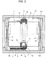
図2は、4:1ケーブルガイダンスを有する本発明によるエレベータの平面図を示す。第1のケージガイドレール15と第2のケージガイドレール16とに沿ってエレベータ昇降路14内を移動可能なエレベータケージ1は、ドア駆動装置(図示せず)によって階ドア18と協働する少なくとも一つのケージ引戸(滑動ドア)17を有する。釣合い重り2は、第1の釣合い重りガイドレール19と第2の釣合い重りガイドレール20とに沿ってエレベータ昇降路14内を移動可能であり、この昇降路は昇降路壁14.1と昇降路天井14.2とによって境界が決められている。エレベータ昇降路14の最上部は、昇降路ヘッド14.3と呼ばれる。ケーブル4は、平行にガイドされる数本のケーブルを有するケーブルランとして構成される。簡略化のために用語「ケーブル」は、引き続き使用される。ケーブル4の代わりに平ベルトを設けることもできる。偏向ローラ7、8、9、10、11、12と駆動プーリ3は、ケーブルまたは平ベルトの本数に対応して溝を持っている。駆動ユニット5は、例えば永久磁石を有する非同期モータまたは同期モータを備えることができる。
FIG. 2 shows a plan view of an elevator according to the invention with 4: 1 cable guidance. The
偏向ローラ7、8、9、10、11、12と駆動プーリ3と駆動ユニット5との配置は、図2の平面図から明らかであるが、駆動プーリ3を有する駆動ユニット5の長手方向の軸は、少なくとも釣合い重り2のガイドレール19、20が配置される昇降路壁に垂直に延びている。
The arrangement of the
図3と図4は、本発明によるエレベータの駆動ユニット5と第1の上部偏向ローラ8との配置の詳細を示す。キャリヤ21は、第1のケージガイドレール15と第1の釣合い重りガイドレール19との一方の端と、第2の釣合い重りガイドレール20の他方の端とに支持されている。これらのガイドレールは、ヨーク22によって昇降路壁14.1に連結されており、これによって垂直レール力は、昇降路ピットに伝えられる。キャリヤ21に配置された駆動ブラケット23は、駆動ユニット5と駆動プーリ3とを支持する。キャリヤ21に配置されたローラブラケット24は、第1の上部偏向ローラ8を支持する。更に第1の上部ケーブル固定点6と第2の上部ケーブル固定点13とがキャリヤ21に配置されている。
3 and 4 show details of the arrangement of the
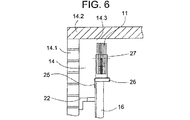
図5と図6は、本発明によるエレベータの第2の上部偏向ローラ11の配置の詳細を示す。ローラブラケット25は、第2のケージガイドレール16上に支持され、第2の上部偏向ローラ11を支持する。ローラブラケット25は、速度制限器27が搭載され得るアーム26を備える。ガイドレール11は、ヨーク22によって昇降路壁14.1に連結され、それによって垂直レール力は昇降路ピットに伝えられる。
5 and 6 show details of the arrangement of the second
図7は、駆動プーリ3を有する駆動ユニット5の配置の構造的変形を示す。駆動プーリ3を有する駆動ユニット5の長手方向の軸は、少なくとも釣合い重り2のガイドレール19、20が配置される昇降路壁に平行に延びる。釣合い重り2の偏向ローラ7、9とキャリヤ21の偏向ローラ8は、傾けて配置される。再び、ケーブル固定点6、13はキャリヤ21に配置される。
FIG. 7 shows a structural variant of the arrangement of the
1 エレベータケージ
2 釣合い重り
3 駆動プーリ
4 ケーブル
5 駆動ユニット
6 第1のケーブル固定点
7、8 第1の偏向ローラ
9、11 第2の偏向ローラ
10 第1の偏向ローラ対
12 第2の偏向ローラ対
13 第2のケーブル固定点
14 エレベータ昇降路
14.1 昇降路壁
14.2 昇降路天井
14.3 昇降路ヘッド
15 第1のケージガイドレール
16 ガイドレール
17 ケージ引戸
18 階ドア
19 第1の釣合い重りガイドレール
20 第2の釣合い重りガイドレール
21 キャリヤ
22 ヨーク
23 駆動装置ブラケット
24、25 ローラブラケット
26 アーム
27 速度制限器
DESCRIPTION OF
Claims (5)
Applications Claiming Priority (2)
| Application Number | Priority Date | Filing Date | Title |
|---|---|---|---|
| EP04006065.9 | 2004-03-15 | ||
| EP04006065 | 2004-03-15 |
Related Parent Applications (1)
| Application Number | Title | Priority Date | Filing Date |
|---|---|---|---|
| JP2005066649A Division JP2005263490A (en) | 2004-03-15 | 2005-03-10 | Elevator for large load |
Publications (1)
| Publication Number | Publication Date |
|---|---|
| JP2012246145A true JP2012246145A (en) | 2012-12-13 |
Family
ID=34924490
Family Applications (2)
| Application Number | Title | Priority Date | Filing Date |
|---|---|---|---|
| JP2005066649A Withdrawn JP2005263490A (en) | 2004-03-15 | 2005-03-10 | Elevator for large load |
| JP2012179701A Ceased JP2012246145A (en) | 2004-03-15 | 2012-08-14 | Elevator for large load |
Family Applications Before (1)
| Application Number | Title | Priority Date | Filing Date |
|---|---|---|---|
| JP2005066649A Withdrawn JP2005263490A (en) | 2004-03-15 | 2005-03-10 | Elevator for large load |
Country Status (4)
| Country | Link |
|---|---|
| US (1) | US7549514B2 (en) |
| JP (2) | JP2005263490A (en) |
| BR (1) | BRPI0500858B1 (en) |
| CA (1) | CA2500616C (en) |
Families Citing this family (27)
| Publication number | Priority date | Publication date | Assignee | Title |
|---|---|---|---|---|
| EP1510493A1 (en) * | 2003-08-12 | 2005-03-02 | Inventio Ag | Elevator system with load-related cable hitch |
| PL1768923T3 (en) * | 2004-07-12 | 2009-04-30 | Inventio Ag | Lift and pulley assembly for use in a lift |
| WO2007149079A1 (en) * | 2006-06-21 | 2007-12-27 | Otis Elevator Company | Governor for an elevator system |
| JP4940823B2 (en) * | 2006-08-18 | 2012-05-30 | フジテック株式会社 | Elevator equipment |
| JP4900971B2 (en) * | 2008-11-05 | 2012-03-21 | 東芝エレベータ株式会社 | Elevator system |
| JP2010184791A (en) * | 2009-02-13 | 2010-08-26 | Toshiba Elevator Co Ltd | Elevator |
| WO2010148102A1 (en) * | 2009-06-16 | 2010-12-23 | Wei Tian | Machine-room-less elevator system and method thereof |
| WO2012115632A1 (en) | 2011-02-23 | 2012-08-30 | Otis Elevator Company | Elevator system including a 4:1 roping arrangement |
| WO2012138335A1 (en) * | 2011-04-06 | 2012-10-11 | Otis Elevator Company | Elevator system including a 4:1 roping arrangement |
| CN102134037A (en) * | 2011-04-14 | 2011-07-27 | 广东菱王电梯有限公司 | Counterweight distribution mode of goods lift of 4:1 small machine room |
| US8757327B2 (en) * | 2011-04-15 | 2014-06-24 | L-3 Communications Integrated Systems Lp | Vehicle elevator systems and methods |
| JP5693723B2 (en) * | 2011-06-27 | 2015-04-01 | 三菱電機株式会社 | Double deck elevator |
| US9815665B2 (en) * | 2012-01-06 | 2017-11-14 | Otis Elevator Company | Battery mounting in elevator hoistway |
| FI125124B (en) * | 2012-05-23 | 2015-06-15 | Kone Corp | Lift arrangement and method |
| WO2014070208A1 (en) | 2012-11-05 | 2014-05-08 | Otis Elevator Company | System including structurally independent elevator machine guiderail mounts |
| CN103086228A (en) * | 2013-01-28 | 2013-05-08 | 舒马克电梯(张家港)有限公司 | Counter-weight rope head structure of elevator with machine room |
| ES2624221T3 (en) * | 2013-02-14 | 2017-07-13 | Kone Corporation | An elevator |
| JP5951104B2 (en) * | 2013-03-04 | 2016-07-13 | 三菱電機株式会社 | Elevator repair method |
| ES2564378T3 (en) * | 2013-08-26 | 2016-03-22 | Kone Corporation | An elevator |
| WO2016024347A1 (en) * | 2014-08-13 | 2016-02-18 | 三菱電機株式会社 | Machine base attaching device for elevator hoisting machine |
| CN106687406B (en) * | 2014-08-28 | 2021-09-07 | 奥的斯电梯公司 | Counterweight for elevator system |
| CN104773634B (en) * | 2015-04-09 | 2017-08-15 | 日立电梯(中国)有限公司 | A kind of elevator traction system |
| US10745246B2 (en) * | 2015-04-17 | 2020-08-18 | Otis Elevator Company | Elevator system |
| EP3235770B1 (en) * | 2016-04-18 | 2019-02-20 | Ziehl-Abegg SE | Method for retrofitting an elevator and corresponding elevator |
| CN110709344B (en) * | 2017-06-06 | 2021-03-26 | 株式会社日立制作所 | Elevator with a movable elevator car |
| CN109720964A (en) | 2017-10-27 | 2019-05-07 | 奥的斯电梯公司 | Elevator traction system and elevator device |
| JP6690766B1 (en) * | 2019-09-04 | 2020-04-28 | フジテック株式会社 | Elevators and fixtures |
Citations (4)
| Publication number | Priority date | Publication date | Assignee | Title |
|---|---|---|---|---|
| JPH08208152A (en) * | 1994-11-03 | 1996-08-13 | Kone Oy | Traction sheave elevator |
| JP2000153975A (en) * | 1998-11-05 | 2000-06-06 | Kone Corp | Elevator with tow sheave |
| JP2002179355A (en) * | 2000-12-19 | 2002-06-26 | Toshiba Corp | Elevator |
| WO2003064309A1 (en) * | 2002-01-30 | 2003-08-07 | Mitsubishi Denki Kabushiki Kaisha | Elevator device |
Family Cites Families (14)
| Publication number | Priority date | Publication date | Assignee | Title |
|---|---|---|---|---|
| FI100516B (en) * | 1994-09-27 | 1997-12-31 | Kone Oy | Arrangement for attaching a carrier line to an elevator and for using a guide as a carrier for an elevator |
| US5833031A (en) * | 1995-06-02 | 1998-11-10 | Inventio Ag | Appendable elevator system |
| DE59711827D1 (en) * | 1996-12-03 | 2004-09-09 | Inventio Ag | Modular elevator |
| US5899300A (en) * | 1996-12-20 | 1999-05-04 | Otis Elevator Company | Mounting for an elevator traction machine |
| WO1999016694A2 (en) * | 1997-10-01 | 1999-04-08 | Wittur Aufzugteile Gmbh & Co. | Preassembled elevator shaft |
| BR9814357A (en) * | 1997-12-23 | 2000-10-17 | Inventio Ag | Cable lifter with motor disc |
| DE29924745U1 (en) | 1998-02-26 | 2005-06-09 | Otis Elevator Co., Farmington | Directional match of flat ropes for elevators |
| JP4047462B2 (en) * | 1998-09-03 | 2008-02-13 | 東芝エレベータ株式会社 | Elevator governor |
| FI111622B (en) * | 1999-01-27 | 2003-08-29 | Kone Corp | Drive wheel lift and flywheel operation |
| DE60045199D1 (en) * | 2000-09-20 | 2010-12-16 | Mitsubishi Electric Corp | elevator |
| WO2002026611A1 (en) * | 2000-09-27 | 2002-04-04 | Inventio Ag | Elevator with drive unit mounted in a superior lateral section of the elevator hoistway |
| JP2002167137A (en) * | 2000-11-29 | 2002-06-11 | Toshiba Corp | Elevator |
| ATE317368T1 (en) | 2001-07-26 | 2006-02-15 | Inventio Ag | INSTALLATION ARRANGEMENT OF AN ELEVATOR DRIVE IN AN ELEVATOR SHAFT |
| JP3991657B2 (en) * | 2001-11-15 | 2007-10-17 | 株式会社日立製作所 | elevator |
-
2005
- 2005-03-10 JP JP2005066649A patent/JP2005263490A/en not_active Withdrawn
- 2005-03-11 CA CA2500616A patent/CA2500616C/en not_active Expired - Fee Related
- 2005-03-14 BR BRPI0500858-1A patent/BRPI0500858B1/en not_active IP Right Cessation
- 2005-03-15 US US11/080,157 patent/US7549514B2/en active Active
-
2012
- 2012-08-14 JP JP2012179701A patent/JP2012246145A/en not_active Ceased
Patent Citations (4)
| Publication number | Priority date | Publication date | Assignee | Title |
|---|---|---|---|---|
| JPH08208152A (en) * | 1994-11-03 | 1996-08-13 | Kone Oy | Traction sheave elevator |
| JP2000153975A (en) * | 1998-11-05 | 2000-06-06 | Kone Corp | Elevator with tow sheave |
| JP2002179355A (en) * | 2000-12-19 | 2002-06-26 | Toshiba Corp | Elevator |
| WO2003064309A1 (en) * | 2002-01-30 | 2003-08-07 | Mitsubishi Denki Kabushiki Kaisha | Elevator device |
Also Published As
| Publication number | Publication date |
|---|---|
| JP2005263490A (en) | 2005-09-29 |
| BRPI0500858A (en) | 2006-11-14 |
| US7549514B2 (en) | 2009-06-23 |
| CA2500616A1 (en) | 2005-09-15 |
| CA2500616C (en) | 2013-01-08 |
| BRPI0500858B1 (en) | 2017-11-14 |
| US20050217943A1 (en) | 2005-10-06 |
Similar Documents
| Publication | Publication Date | Title |
|---|---|---|
| JP2012246145A (en) | Elevator for large load | |
| JP5044102B2 (en) | A device for accurately positioning each cage of an elevator multistage cage | |
| JP4823079B2 (en) | Drive machine for elevator apparatus and method for mounting drive machine | |
| JP4629963B2 (en) | Elevator apparatus and method for arranging drive machine of elevator apparatus | |
| EP2576408B1 (en) | Elevator with roller-pinion drive | |
| US6848543B2 (en) | Single wall interface traction elevator | |
| JP2005509580A (en) | Elevator system | |
| JP2005509580A5 (en) | ||
| CN100347070C (en) | Elevator installation, a method of operating this elevator installation, and method of modernizing an elevator installation | |
| JP2008156116A (en) | Elevator with two elevator cars disposed one above the other in shaft | |
| US10035682B2 (en) | Apparatus for fixing a hoisting machine of an elevator and a fixing arrangement | |
| JP4657612B2 (en) | elevator | |
| JP2006519742A (en) | elevator | |
| KR101335800B1 (en) | Elevator device | |
| JP5800916B2 (en) | Elevator equipment with 4: 1 roping | |
| EP1754680A1 (en) | Elevator apparatus | |
| CN1833981B (en) | Elevator system | |
| JP6318022B2 (en) | Elevator | |
| JP4866849B2 (en) | Machine roomless elevator car guide device | |
| EP3274285B1 (en) | Elevator system suspension member termination | |
| JP2011001153A (en) | Elevator device | |
| JPH02310278A (en) | Linear motor driven elevator | |
| KR20060005999A (en) | Elevator apparatus | |
| US20150122586A1 (en) | Elevator system incorporating a traveling motor | |
| JPH05155561A (en) | Linear-mot0r driven elevator device |
Legal Events
| Date | Code | Title | Description |
|---|---|---|---|
| A521 | Request for written amendment filed |
Free format text: JAPANESE INTERMEDIATE CODE: A523 Effective date: 20120912 |
|
| A621 | Written request for application examination |
Free format text: JAPANESE INTERMEDIATE CODE: A621 Effective date: 20120912 |
|
| A977 | Report on retrieval |
Free format text: JAPANESE INTERMEDIATE CODE: A971007 Effective date: 20131127 |
|
| A131 | Notification of reasons for refusal |
Free format text: JAPANESE INTERMEDIATE CODE: A131 Effective date: 20131203 |
|
| A601 | Written request for extension of time |
Free format text: JAPANESE INTERMEDIATE CODE: A601 Effective date: 20140228 |
|
| A602 | Written permission of extension of time |
Free format text: JAPANESE INTERMEDIATE CODE: A602 Effective date: 20140305 |
|
| A521 | Request for written amendment filed |
Free format text: JAPANESE INTERMEDIATE CODE: A523 Effective date: 20140403 |
|
| A131 | Notification of reasons for refusal |
Free format text: JAPANESE INTERMEDIATE CODE: A131 Effective date: 20140930 |
|
| A601 | Written request for extension of time |
Free format text: JAPANESE INTERMEDIATE CODE: A601 Effective date: 20141226 |
|
| A521 | Request for written amendment filed |
Free format text: JAPANESE INTERMEDIATE CODE: A523 Effective date: 20150130 |
|
| A01 | Written decision to grant a patent or to grant a registration (utility model) |
Free format text: JAPANESE INTERMEDIATE CODE: A01 Effective date: 20150818 |
|
| A045 | Written measure of dismissal of application [lapsed due to lack of payment] |
Free format text: JAPANESE INTERMEDIATE CODE: A045 Effective date: 20151222 |