JP2012244726A - Armature for rotary electric machine and rotary electric machine - Google Patents
Armature for rotary electric machine and rotary electric machine Download PDFInfo
- Publication number
- JP2012244726A JP2012244726A JP2011111372A JP2011111372A JP2012244726A JP 2012244726 A JP2012244726 A JP 2012244726A JP 2011111372 A JP2011111372 A JP 2011111372A JP 2011111372 A JP2011111372 A JP 2011111372A JP 2012244726 A JP2012244726 A JP 2012244726A
- Authority
- JP
- Japan
- Prior art keywords
- winding
- armature
- stator
- slot
- speed
- Prior art date
- Legal status (The legal status is an assumption and is not a legal conclusion. Google has not performed a legal analysis and makes no representation as to the accuracy of the status listed.)
- Pending
Links
Images


Abstract
Description
本発明は、回転電機の電機子および回転電機に関する。 The present invention relates to an armature of a rotating electrical machine and a rotating electrical machine.
従来、電動機や発電機などの回転電機の一つとして、巻線切替型の回転電機が知られている。巻線切替型の回転電機は、各相ごとに複数の巻線を備え、これら複数の巻線の接続状態を切り替えることにより、低速領域から高速領域までの広い範囲において効率的な駆動を可能とする回転電機である(特許文献1参照)。 2. Description of the Related Art Conventionally, a winding switching type rotating electrical machine is known as one of rotating electrical machines such as an electric motor and a generator. The winding switching type rotating electrical machine has a plurality of windings for each phase, and by switching the connection state of the plurality of windings, it is possible to drive efficiently in a wide range from a low speed region to a high speed region. (See Patent Document 1).
たとえば、かかる巻線切替型の回転電機は、各相ごとに2つの電機子巻線を備える場合には、両方の電機子巻線を用いることで低速駆動に対応し、一方の電機子巻線のみを用いることで高速駆動に対応する。 For example, when the winding-switching type rotating electric machine includes two armature windings for each phase, both armature windings are used to support low-speed driving. High speed drive is supported by using only.
しかしながら、上述した従来技術には、高速駆動状態における効率を向上させるという点でさらなる改善の余地がある。 However, the above-described conventional technology has room for further improvement in terms of improving efficiency in a high-speed driving state.
開示の技術は、上記に鑑みてなされたものであって、高速駆動状態における効率を向上させることができる回転電機の電機子および回転電機を提供することを目的とする。 The disclosed technique has been made in view of the above, and an object thereof is to provide an armature of a rotating electrical machine and a rotating electrical machine that can improve efficiency in a high-speed driving state.
本願の開示する回転電機の電機子は、周方向に沿って複数のスロットが形成された電機子コアと、前記電機子コアのスロットへ設けられ、第1速度状態および該第1速度状態よりも低速な第2速度状態の両状態において用いられる第1の電機子巻線と、前記第1の電機子巻線が設けられたスロットと同一のスロットへ設けられ、前記第2速度状態において用いられる第2の電機子巻線とを備え、前記第1の電機子巻線の巻数が前記第2の電機子巻線の巻数よりも多い。 An armature of a rotating electrical machine disclosed in the present application is provided in an armature core in which a plurality of slots are formed along a circumferential direction, and in the slot of the armature core, and the first speed state and the first speed state The first armature winding used in both the low-speed second speed state and the same slot as the slot in which the first armature winding is provided are used in the second speed state. A second armature winding, wherein the number of turns of the first armature winding is greater than the number of turns of the second armature winding.
また、本願の開示する回転電機は、電機子および界磁を備える回転電機であって、前記電機子は、周方向に沿って複数のスロットが形成された電機子コアと、前記電機子コアのスロットへ設けられ、第1速度状態および該第1速度状態よりも低速な第2速度状態の両状態において用いられる第1の電機子巻線と、前記電機子コアのスロットへ設けられ、前記第2速度状態において用いられる第2の電機子巻線とを備え、前記第1の電機子巻線の巻数が前記第2の電機子巻線の巻数よりも多い。 A rotating electrical machine disclosed in the present application is a rotating electrical machine including an armature and a field, and the armature includes: an armature core having a plurality of slots formed along a circumferential direction; and the armature core. A first armature winding provided in a slot and used in both a first speed state and a second speed state lower than the first speed state; and provided in a slot of the armature core; A second armature winding used in a two-speed state, wherein the number of turns of the first armature winding is larger than the number of turns of the second armature winding.
本願の開示する回転電機の電機子および回転電機の一つの態様によれば、高速駆動状態における効率を向上させることができる。 According to one aspect of the armature of a rotating electrical machine and the rotating electrical machine disclosed in the present application, the efficiency in a high-speed driving state can be improved.
以下に添付図面を参照して、本願の開示する回転電機の電機子および回転電機のいくつかの実施例を詳細に説明する。 DESCRIPTION OF EMBODIMENTS Hereinafter, an embodiment of a rotating electrical machine armature and a rotating electrical machine disclosed in the present application will be described in detail with reference to the accompanying drawings.
なお、以下に示す各実施例では、本願の開示する回転電機を電動機であるモータに対して適用した場合の例について説明する。また、以下に示す各実施例では、本願の開示する電機子が固定子である場合、すなわち、電機子巻線が固定子側へ設けられる場合の例について説明する。ただし、これらの例示によって本発明が限定されるものではない。 In each embodiment described below, an example in which the rotating electrical machine disclosed in the present application is applied to a motor that is an electric motor will be described. In each of the following embodiments, an example in which the armature disclosed in the present application is a stator, that is, an armature winding is provided on the stator side will be described. However, the present invention is not limited to these examples.
まず、本実施例1に係るモータの構成について図1を用いて説明する。図1は、実施例1に係るモータをシャフトの軸方向から見た図である。図1に示すように、実施例1に係るモータ1は、固定子10と、回転子20と、シャフト30とを備える。
First, the configuration of the motor according to the first embodiment will be described with reference to FIG. FIG. 1 is a diagram of the motor according to the first embodiment when viewed from the axial direction of the shaft. As shown in FIG. 1, the motor 1 according to the first embodiment includes a
固定子10は、固定子コア11と、固定子巻線12とを備え、回転子20の外周面と所定の空隙を介して対向配置される。
The
固定子コア11は、電磁鋼板などの薄板材を多数枚積層して形成される円筒状の部材である。かかる固定子コア11の内周側には、径方向内側へ突出したティース111が周方向に沿って多数形成される。これらティース111間の空間は、スロット112と呼ばれる。
The
スロット112の内周面は絶縁材で覆われており、かかるスロット112内に絶縁被覆電線を用いて巻装された固定子巻線12が収められる。なお、固定子巻線12は、集中巻線方式で巻装されるものとするが、これに限ったものではなく、分布巻線方式で巻装されてもよい。
The inner peripheral surface of the
回転子20は、回転子コア21と、永久磁石22とを備える。回転子コア21は、筒状に形成され、内部には複数の永久磁石22が周方向に沿って配設される。かかる回転子20は、シャフト30に取り付けられており、かかるシャフト30を中心軸として回転する。
The
なお、ここでは、回転子20の構成として、永久磁石22が回転子コア21の内部に配設されたIPM(Interior Permanent Magnet)を例に挙げて説明するが、これに限ったものではなく、回転子の構成は、回転子コアの外周面に永久磁石が配設されたSPM(Surface Permanent Magnet)であってもよい。
Here, as an example of the configuration of the
また、ここでは、永久磁石式のモータを例に挙げたが、これに限ったものではなく、モータ1は、たとえば電磁石式などの永久磁石式以外のモータであってもよい。 In addition, here, a permanent magnet type motor is described as an example, but the present invention is not limited to this, and the motor 1 may be a motor other than a permanent magnet type such as an electromagnet type.
また、図1では、モータが、6個の回転子20および40個のスロット112を備える6極40スロットのモータである場合の例について示したが、回転子20やスロット112の数は、これに限ったものではない。たとえば、モータは、6個の回転子20および36個のスロット112を備える6極36スロットのモータであってもよい。
Further, FIG. 1 shows an example in which the motor is a 6-pole 40-slot motor including six
モータ1では、固定子10の固定子巻線12に電流を流すことによって固定子10の内側に回転磁界が発生する。そして、この回転磁界と回転子20の永久磁石22が発生する磁界との相互作用によって回転子20が回転し、この回転子20の回転に伴ってシャフト30が回転する。
In the motor 1, a rotating magnetic field is generated inside the
ここで、本実施例1に係るモータ1は、巻線切替型のモータである。具体的には、モータ1は、固定子巻線12として、第1巻線121および第2巻線122の2つの固定子巻線を備える。モータ1は、第1巻線121および第2巻線122の接続状態を切り替えることで、低速領域から高速領域までの広い範囲において効率的な駆動を可能とする。
Here, the motor 1 according to the first embodiment is a winding switching type motor. Specifically, the motor 1 includes two stator windings of a first winding 121 and a second winding 122 as the stator winding 12. The motor 1 enables efficient driving in a wide range from the low speed region to the high speed region by switching the connection state of the
特に、本実施例1に係るモータ1は、高速駆動状態における効率を向上させるために、第1巻線121の巻数と第2巻線122の巻数とを異ならせることとした。
In particular, in the motor 1 according to the first embodiment, the number of turns of the
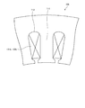
以下では、固定子10の構成について図2を用いて具体的に説明する。図2は、実施例1に係る固定子10の構成を示す図である。ここで、図2には、図1に示す固定子10のティース111周辺を拡大した図を示している。
Below, the structure of the
なお、以下では、モータ1の回転速度が所定の閾値以上である第1速度状態を「高速駆動状態」と呼び、回転速度が所定の閾値未満である第2速度状態を「低速駆動状態」と呼ぶこととする。 Hereinafter, the first speed state in which the rotational speed of the motor 1 is equal to or higher than a predetermined threshold is referred to as a “high-speed driving state”, and the second speed state in which the rotational speed is lower than the predetermined threshold is referred to as a “low-speed driving state”. I will call it.
図2に示すように、固定子10のスロット112には、第1巻線121および第2巻線122が収められる。第1巻線121は、高速駆動状態および低速駆動状態の両状態において用いられる固定子巻線であり、第2巻線122は、低速駆動状態においてのみ用いられる固定子巻線である。
As shown in FIG. 2, the
これら第1巻線121および第2巻線122は、直列に接続され、同一のスロット112へ設けられる。なお、第1巻線121および第2巻線122は、並列に接続されてもよい。
The first winding 121 and the
モータ1の回転速度が閾値未満である場合、すなわち、低速駆動状態である場合には、第1巻線121および第2巻線122に対して通電される。これにより、固定子巻線12のインピーダンスが最大の状態となる。かかる状態では、高トルクを得やすい反面、高い回転速度を出すことが難しい。
When the rotation speed of the motor 1 is less than the threshold value, that is, when the motor 1 is in a low-speed driving state, the
一方、モータ1の回転速度が閾値以上である場合、すなわち、高速駆動状態である場合には、第1巻線121のみに対して通電される。これにより、低速駆動状態と比較して固定子巻線12のインピーダンスが小さくなるため、高い回転速度を得やすくなる。
On the other hand, when the rotation speed of the motor 1 is equal to or higher than the threshold value, that is, when the motor 1 is in a high-speed driving state, only the
このように、モータ1は、低速駆動状態では第1巻線121および第2巻線122が通電され、高速駆動状態では第1巻線121のみが通電されるように第1巻線121および第2巻線122の接続状態を切り替える。
Thus, in the motor 1, the first winding 121 and the second winding 122 are energized in the low speed driving state, and only the first winding 121 is energized in the high speed driving state. The connection state of the two
なお、第1巻線121および第2巻線122の接続状態の切り替えは、モータ1の駆動を制御する制御装置によって行われることとなるが、かかる点については、図3および図4を用いて後述する。 Note that the switching of the connection state of the first winding 121 and the second winding 122 is performed by a control device that controls the driving of the motor 1, but this point will be described with reference to FIG. 3 and FIG. It will be described later.
本実施例1では、第1巻線121の巻数を第2巻線122の巻数よりも多くしている。これにより、たとえば第1巻線の巻数および第2巻線の巻数を同一とした場合と比較して、高速駆動状態、すなわち、第1巻線121のみが使用される状態における占積率を向上させることができる。占積率が高くなるほど銅損等の損失が少なくなるため、第1巻線121の巻数を第2巻線122の巻数よりも多くすることで、高速駆動状態における効率を向上させることができる。 In the first embodiment, the number of turns of the first winding 121 is larger than the number of turns of the second winding 122. This improves the space factor in a high-speed driving state, that is, in a state where only the first winding 121 is used, for example, compared to the case where the number of turns of the first winding and the number of turns of the second winding are the same. Can be made. Since the loss such as copper loss decreases as the space factor increases, the efficiency in the high-speed driving state can be improved by increasing the number of turns of the first winding 121 than the number of turns of the second winding 122.
また、本実施例1では、スロット112の領域のうち固定子10の外周側の領域に対して第1巻線121を設け、内周側の領域に対して第2巻線122を設けることとした。これにより、固定子10の外周側の領域に対して第2巻線122を設け、内周側の領域に対して第1巻線121を設けた場合と比較して、スロット112と固定子巻線12との接触面積を増やすことができるため、固定子巻線12において発生した熱のスロット112への放熱効果を高めることができる。
In the first embodiment, the first winding 121 is provided in the outer peripheral side region of the
なお、第1巻線121および第2巻線122の巻数比は、1.2:0.8であることが好ましいが、第1巻線121の巻数が第2巻線122の巻数よりも多ければ、他の比率であっても構わない。 Note that the turn ratio of the first winding 121 and the second winding 122 is preferably 1.2: 0.8, but the number of turns of the first winding 121 is larger than the number of turns of the second winding 122. For example, other ratios may be used.
次に、モータ1を含む駆動システムの構成例について図3を用いて説明する。図3は、駆動システムの構成を示すブロック図である。なお、本実施例に係る駆動システムは、たとえば、電気自動車や産業用ロボット等の駆動システムに対して適用することができる。 Next, a configuration example of a drive system including the motor 1 will be described with reference to FIG. FIG. 3 is a block diagram showing the configuration of the drive system. The drive system according to the present embodiment can be applied to a drive system such as an electric vehicle or an industrial robot.
図3に示すように、本実施例に係る駆動システムは、モータ1と、速度検出部2と、電源部3と、切替器4a,4bと、制御部5とを含んで構成される。なお、図3では、駆動システムの特徴を説明するために必要な構成要素のみを示しており、一般的な構成要素についての記載を省略している。
As shown in FIG. 3, the drive system according to this embodiment includes a motor 1, a
速度検出部2は、モータ1の回転速度を検出する検出部である。かかる速度検出部2によって検出された回転速度は、制御部5へ出力される。なお、速度検出部2としては、たとえば、エンコーダやレゾルバ等を用いることができる。
The
電源部3は、モータ1に対して駆動電力を供給する。切替器4aは、制御部5からの指示に従い、第1巻線121に対する通電状態のオン/オフを切り替える。また、切替器4bは、制御部5からの指示に従い、第2巻線122に対する通電状態のオン/オフを切り替える切替器である。
The power supply unit 3 supplies driving power to the motor 1. The
制御部5は、速度検出部2によって検出されるモータ1の回転速度に基づいて切替器4a,4bの切り替えを行う制御部である。
The
ここで、制御部5が実行する処理手順について図4を用いて説明する。図4は、制御部5が実行する処理手順を示すフローチャートである。なお、図4においては、制御部5が、速度検出部2から回転速度を取得してから切替器4a,4bの切り替えを行うまでの処理手順について示している。
Here, a processing procedure executed by the
図4に示すように、制御部5は、速度検出部2からモータ1の回転速度を取得し(ステップS101)、モータ1の現在の駆動状態が低速駆動状態であるか否かを判定する(ステップS102)。具体的には、制御部5は、取得した回転速度が所定の閾値未満であれば低速駆動状態であると判定し、所定の閾値以上であれば高速駆動状態であると判定する。
As shown in FIG. 4, the
なお、制御部5は、たとえば、所定の閾値を図示しない記憶部にあらかじめ記憶しており、かかる記憶部から所定の閾値を読み出し、速度検出部2から取得した回転速度と比較するものとする。
The
かかる処理においてモータ1の現在の駆動状態が低速駆動状態であると判定した場合(ステップS102,Yes)、制御部5は、第1巻線121および第2巻線122に対して通電を行う(ステップS103)。すなわち、制御部5は、切替器4aおよび切替器4bを共にオンに切り替えて、処理を終了する。
When it determines with the present drive state of the motor 1 being a low speed drive state in this process (step S102, Yes), the
一方、モータ1の現在の駆動状態が低速駆動状態ではない場合(ステップS102,No)、すなわち、高速駆動状態である場合には、第1巻線121のみに対して通電を行う(ステップS104)。すなわち、制御部5は、切替器4aをオンに切り替えるとともに、切替器4bをオフに切り替えて、処理を終了する。
On the other hand, when the current drive state of the motor 1 is not the low-speed drive state (No at Step S102), that is, when it is the high-speed drive state, only the first winding 121 is energized (Step S104). . That is, the
上述してきたように、本実施例1では、モータ1が、周方向に沿って複数のスロット112が形成された固定子コア11と、固定子コア11のスロット112へ設けられ、高速駆動状態および低速駆動状態の両状態において用いられる第1巻線121と、スロット112へ設けられ、低速駆動状態において用いられる第2巻線122とを備え、第1巻線121の巻数を第2巻線122の巻数よりも多くした。したがって、第1巻線の巻数および第2巻線の巻数を同一とした場合と比較して、高速駆動状態における占積率が向上し、損失が低下するため、高速駆動状態における効率を向上させることができる。
As described above, in the first embodiment, the motor 1 is provided in the
また、本実施例1では、第1巻線121を、スロット112の領域のうち、第2巻線122よりも回転子20から遠い側の領域へ設けることとした。したがって、固定子巻線12において発生した熱のスロット112への放熱効果を高めることができる。
In the first embodiment, the first winding 121 is provided in a region of the
ところで、上述してきた実施例1では、スロット112の領域のうち固定子10の外周側の領域に対して第1巻線121を設け、内周側の領域に対して第2巻線122を設けることとした。しかし、第1巻線および第2巻線の配置関係は、これに限ったものではない。
In the first embodiment described above, the first winding 121 is provided in the outer peripheral side region of the
以下では、第1巻線および第2巻線の配置関係の他の例について図5を用いて説明する。図5は、実施例2に係る固定子の構成を示す図である。なお、以下では、既に説明した部分と同様の部分については、既に説明した部分と同一の符号を付し、重複する説明を省略する。 Hereinafter, another example of the arrangement relationship between the first winding and the second winding will be described with reference to FIG. FIG. 5 is a diagram illustrating the configuration of the stator according to the second embodiment. In the following description, the same parts as those already described are denoted by the same reference numerals as those already described, and redundant description is omitted.
図5に示すように、実施例2に係る固定子10aでは、実施例1に係る固定子10とは異なり、高速駆動状態および低速駆動状態の両状態において用いる第1巻線121aが、スロット112の領域のうち固定子10aの内周側の領域に対して設けられる。また、固定子10aでは、低速駆動状態において用いる第2巻線122aが、スロット112の領域のうち固定子10aの外周側の領域に対して設けられる。
As shown in FIG. 5, in the
すなわち、実施例2では、隣接するティース111間の距離が短い領域に対して、巻数がより多い第1巻線121aを設けることとした。これにより、実施例1のように固定子10の外周側の領域に対して第1巻線121を設け、内周側の領域に対して第2巻線122を設けた場合と比較して、漏れインダクタンスの発生を抑えることができる。なお、実施例1と同様、第1巻線121aの巻数は、第2巻線122aの巻数よりも多い。
That is, in Example 2, the first winding 121a having a larger number of turns is provided in a region where the distance between
上述したように実施例2では、第1巻線121aを、スロット112の領域のうち、第2巻線122aよりも回転子20に近い側の領域へ設けることとしたため、漏れインダクタンスの発生を低減することができる。
As described above, in the second embodiment, since the first winding 121a is provided in the region closer to the
また、第1巻線および第2巻線は、スロット112の同一の領域に設けることとしてもよい。以下では、かかる場合の例について図6を用いて説明する。図6は、実施例3に係る固定子の構成を示す図である。
The first winding and the second winding may be provided in the same region of the
図6に示すように、実施例3に係る固定子10bでは、実施例1に係る固定子10および実施例2に係る固定子10aとは異なり、第1巻線121bおよび第2巻線122bが、スロット112の同一の領域へ設けられる。
As shown in FIG. 6, in the
具体的には、たとえば、第1巻線121bを巻装したのち第2巻線122bを第1巻線121bの上から巻装すればよい。なお、これに限らず、第2巻線122bを巻装したのち第1巻線121bを第2巻線122bの上から巻装してもよいし、第1巻線121bおよび第2巻線122bを同時に巻装させてもよい。 Specifically, for example, after winding the first winding 121b, the second winding 122b may be wound from above the first winding 121b. Not limited to this, the first winding 121b may be wound from above the second winding 122b after the second winding 122b is wound, or the first winding 121b and the second winding 122b may be wound. May be wound simultaneously.
また、第1巻線121bおよび第2巻線122bは、巻き始めおよび巻き終わりの位置が同一位置となるように、異なる巻回ピッチで巻装されるものとする。ただし、第1巻線121bの巻き始めの位置または巻き終わりの位置は、第2巻線122bの巻き始めの位置または巻き終わりの位置と必ずしも同一位置とする必要はない。すなわち、第1巻線121bの巻装領域および第2巻線122bの巻装領域は完全に重複する必要はなく、第1巻線121bまたは第2巻線122bの巻装領域の一部が、他方の巻装領域の一部と重複していればよい。 The first winding 121b and the second winding 122b are wound at different winding pitches so that the winding start position and winding end position are the same. However, the winding start position or winding end position of the first winding 121b is not necessarily the same position as the winding start position or winding end position of the second winding 122b. That is, the winding region of the first winding 121b and the winding region of the second winding 122b do not have to overlap completely, and a part of the winding region of the first winding 121b or the second winding 122b It only needs to overlap with a part of the other winding area.
このように、第1巻線121bと第2巻線122bとを、スロット112の同一の領域へ設けることとすれば、実施例1に係る固定子10のように固定子巻線12において発生した熱のスロット112への放熱効果を高めることができるとともに、実施例2に係る固定子10aのように漏れインダクタンスの発生も抑えることができる。
As described above, if the first winding 121b and the second winding 122b are provided in the same region of the
なお、上述してきた各実施例では、図1に示すような所謂インナーロータ型のモータに対して本願の開示する回転電機を適用した場合の例について説明してきたが、これに限ったものではなく、本願の開示する回転電機は、固定子の外周側に回転子を配置した所謂アウターロータ型のモータに対して適用することもできる。また、本願の開示する回転電機は、モータのような電動機に限らず、発電機に対して適用することも可能である。 In each of the embodiments described above, an example in which the rotating electrical machine disclosed in the present application is applied to a so-called inner rotor type motor as shown in FIG. 1 has been described. However, the present invention is not limited to this. The rotating electrical machine disclosed in the present application can also be applied to a so-called outer rotor type motor in which a rotor is arranged on the outer peripheral side of the stator. In addition, the rotating electrical machine disclosed in the present application is not limited to an electric motor such as a motor, but can also be applied to a generator.
また、上述してきた各実施例では、本願の開示する電機子が固定子である場合、すなわち、電機子巻線が固定子側へ設けられる場合の例について説明したが、これに限ったものではなく、本願の開示する電機子は、回転子であってもよい。 Further, in each of the embodiments described above, the case where the armature disclosed in the present application is a stator, that is, the case where the armature winding is provided on the stator side has been described, but the present invention is not limited thereto. Instead, the armature disclosed in the present application may be a rotor.
また、上述した各実施例では、第1巻線および第2巻線が、同一のスロットへ設けられる場合の例について説明したが、第1巻線および第2巻線は、実施例3のように同一のスロットの同一の領域へ設ける場合を除き、異なるスロットへ設けてもよい。たとえば、各スロットに対して第1巻線および第2巻線を交互に設けることとしてもよい。 In each of the above-described embodiments, an example in which the first winding and the second winding are provided in the same slot has been described. However, the first winding and the second winding are as in the third embodiment. However, they may be provided in different slots, except when they are provided in the same region of the same slot. For example, the first winding and the second winding may be alternately provided for each slot.
さらなる効果や変形例は、当業者によって容易に導き出すことができる。このため、本発明のより広範な態様は、以上のように表しかつ記述した特定の詳細および代表的な実施の形態に限定されるものではない。したがって、添付の特許請求の範囲およびその均等物によって定義される総括的な発明の概念の精神または範囲から逸脱することなく、様々な変更が可能である。 Further effects and modifications can be easily derived by those skilled in the art. Thus, the broader aspects of the present invention are not limited to the specific details and representative embodiments shown and described above. Accordingly, various modifications can be made without departing from the spirit or scope of the general inventive concept as defined by the appended claims and their equivalents.
1 モータ
2 速度検出部
3 電源部
4a,4b 切替器
5 制御部
10,10a,10b 固定子
11 固定子コア
12 固定子巻線
20 回転子
21 回転子コア
22 永久磁石
30 シャフト
111 ティース
112 スロット
121,121a,121b 第1巻線
122,122a,122b 第2巻線
DESCRIPTION OF SYMBOLS 1
Claims (5)
前記電機子コアのスロットへ設けられ、第1速度状態および該第1速度状態よりも低速な第2速度状態の両状態において用いられる第1の電機子巻線と、
前記電機子コアのスロットへ設けられ、前記第2速度状態において用いられる第2の電機子巻線と
を備え、
前記第1の電機子巻線の巻数が前記第2の電機子巻線の巻数よりも多いことを特徴とする回転電機の電機子。 An armature core having a plurality of slots formed along the circumferential direction;
A first armature winding provided in a slot of the armature core and used in both a first speed state and a second speed state that is slower than the first speed state;
A second armature winding provided in a slot of the armature core and used in the second speed state;
An armature for a rotating electrical machine, wherein the number of turns of the first armature winding is larger than the number of turns of the second armature winding.
前記電機子は、
周方向に沿って複数のスロットが形成された電機子コアと、
前記電機子コアのスロットへ設けられ、第1速度状態および該第1速度状態よりも低速な第2速度状態の両状態において用いられる第1の電機子巻線と、
前記電機子コアのスロットへ設けられ、前記第2速度状態において用いられる第2の電機子巻線と
を備え、
前記第1の電機子巻線の巻数が前記第2の電機子巻線の巻数よりも多いことを特徴とする回転電機。 A rotating electric machine having an armature and a field,
The armature is
An armature core having a plurality of slots formed along the circumferential direction;
A first armature winding provided in a slot of the armature core and used in both a first speed state and a second speed state that is slower than the first speed state;
A second armature winding provided in a slot of the armature core and used in the second speed state;
The rotating electrical machine characterized in that the number of turns of the first armature winding is larger than the number of turns of the second armature winding.
Priority Applications (1)
| Application Number | Priority Date | Filing Date | Title |
|---|---|---|---|
| JP2011111372A JP2012244726A (en) | 2011-05-18 | 2011-05-18 | Armature for rotary electric machine and rotary electric machine |
Applications Claiming Priority (1)
| Application Number | Priority Date | Filing Date | Title |
|---|---|---|---|
| JP2011111372A JP2012244726A (en) | 2011-05-18 | 2011-05-18 | Armature for rotary electric machine and rotary electric machine |
Publications (1)
| Publication Number | Publication Date |
|---|---|
| JP2012244726A true JP2012244726A (en) | 2012-12-10 |
Family
ID=47465856
Family Applications (1)
| Application Number | Title | Priority Date | Filing Date |
|---|---|---|---|
| JP2011111372A Pending JP2012244726A (en) | 2011-05-18 | 2011-05-18 | Armature for rotary electric machine and rotary electric machine |
Country Status (1)
| Country | Link |
|---|---|
| JP (1) | JP2012244726A (en) |
Cited By (4)
| Publication number | Priority date | Publication date | Assignee | Title |
|---|---|---|---|---|
| JP2020174497A (en) * | 2019-04-12 | 2020-10-22 | 株式会社kaisei | Three-phase alternator |
| WO2021019703A1 (en) * | 2019-07-30 | 2021-02-04 | 株式会社kaisei | Three-phase ac generator |
| WO2021024645A1 (en) * | 2019-08-06 | 2021-02-11 | 株式会社日立産機システム | Rotary electric machine |
| CN113472113A (en) * | 2020-03-31 | 2021-10-01 | 日本电产株式会社 | Motor |
Citations (4)
| Publication number | Priority date | Publication date | Assignee | Title |
|---|---|---|---|---|
| JPH0522990A (en) * | 1991-07-05 | 1993-01-29 | Fanuc Ltd | Winding switching driving system for induction motor |
| JPH06113517A (en) * | 1992-09-30 | 1994-04-22 | Daikin Ind Ltd | Dc brushless motor |
| JPH10126993A (en) * | 1996-10-21 | 1998-05-15 | Yaskawa Electric Corp | Switching device of winding for motor in machine tool |
| JP2005307867A (en) * | 2004-04-22 | 2005-11-04 | Matsushita Electric Ind Co Ltd | Compressor, compressor drive control device, and drive control method for compressor |
-
2011
- 2011-05-18 JP JP2011111372A patent/JP2012244726A/en active Pending
Patent Citations (4)
| Publication number | Priority date | Publication date | Assignee | Title |
|---|---|---|---|---|
| JPH0522990A (en) * | 1991-07-05 | 1993-01-29 | Fanuc Ltd | Winding switching driving system for induction motor |
| JPH06113517A (en) * | 1992-09-30 | 1994-04-22 | Daikin Ind Ltd | Dc brushless motor |
| JPH10126993A (en) * | 1996-10-21 | 1998-05-15 | Yaskawa Electric Corp | Switching device of winding for motor in machine tool |
| JP2005307867A (en) * | 2004-04-22 | 2005-11-04 | Matsushita Electric Ind Co Ltd | Compressor, compressor drive control device, and drive control method for compressor |
Cited By (7)
| Publication number | Priority date | Publication date | Assignee | Title |
|---|---|---|---|---|
| JP2020174497A (en) * | 2019-04-12 | 2020-10-22 | 株式会社kaisei | Three-phase alternator |
| JP7288337B2 (en) | 2019-04-12 | 2023-06-07 | 株式会社kaisei | three phase alternator |
| WO2021019703A1 (en) * | 2019-07-30 | 2021-02-04 | 株式会社kaisei | Three-phase ac generator |
| WO2021024645A1 (en) * | 2019-08-06 | 2021-02-11 | 株式会社日立産機システム | Rotary electric machine |
| TWI772833B (en) * | 2019-08-06 | 2022-08-01 | 日商日立產機系統股份有限公司 | Rotary motor |
| CN113472113A (en) * | 2020-03-31 | 2021-10-01 | 日本电产株式会社 | Motor |
| CN113472113B (en) * | 2020-03-31 | 2024-04-12 | 日本电产株式会社 | Motor |
Similar Documents
| Publication | Publication Date | Title |
|---|---|---|
| KR101730525B1 (en) | Brushless synchronous motor | |
| US9124161B2 (en) | Double-stator/double-rotor type motor and direct drive apparatus for washer using same | |
| US20130093276A1 (en) | Double-stator/double-rotor type motor and direct drive apparatus for washer using same | |
| JP2010531130A (en) | Synchronous motor having 12 stator teeth and 10 rotor poles | |
| JP2016214070A (en) | Single-phase motor and electric apparatus having the same | |
| US20110018384A1 (en) | Motor | |
| JP5542849B2 (en) | Switched reluctance motor | |
| JP2012517209A (en) | Synchronous machine | |
| JP2015192553A (en) | Insulator and brushless dc motor employing the same | |
| CN104426315B (en) | Three-phase electromagnetic motor | |
| JP2011120465A (en) | Two-phase bldc motor | |
| CN103023264A (en) | Mechanically commutated switched reluctance motor | |
| KR20130021210A (en) | Mechanically commutated switched reluctance motor | |
| JP2013066251A (en) | Rotary electric machine | |
| US20110248582A1 (en) | Switched reluctance machine | |
| JP2012244726A (en) | Armature for rotary electric machine and rotary electric machine | |
| WO2011099567A1 (en) | Stator of rotating electrical machine, and rotating electrical machine | |
| JP2014176284A (en) | Double stator type switched reluctance rotating machine | |
| US20170271930A1 (en) | Rotor having flux filtering function and synchronous motor comprising same | |
| JP2012182942A (en) | Rotary electric machine | |
| JP4927226B1 (en) | High efficiency generator | |
| JP5301905B2 (en) | Multi-phase rotating electrical machine drive device, multi-phase generator converter, multi-phase rotating electrical machine, and rotating electrical machine drive system | |
| JP2006238679A (en) | Single-phase permanent magnet motor | |
| JP2011172369A (en) | Synchronous rotating machine | |
| JP2018148675A (en) | Stator for rotary electric machine |
Legal Events
| Date | Code | Title | Description |
|---|---|---|---|
| A621 | Written request for application examination |
Free format text: JAPANESE INTERMEDIATE CODE: A621 Effective date: 20130201 |
|
| A977 | Report on retrieval |
Free format text: JAPANESE INTERMEDIATE CODE: A971007 Effective date: 20140219 |
|
| A131 | Notification of reasons for refusal |
Free format text: JAPANESE INTERMEDIATE CODE: A131 Effective date: 20140225 |
|
| A521 | Written amendment |
Free format text: JAPANESE INTERMEDIATE CODE: A523 Effective date: 20140421 |
|
| A02 | Decision of refusal |
Free format text: JAPANESE INTERMEDIATE CODE: A02 Effective date: 20141111 |