JP2012242554A - Image forming apparatus - Google Patents
Image forming apparatus Download PDFInfo
- Publication number
- JP2012242554A JP2012242554A JP2011111680A JP2011111680A JP2012242554A JP 2012242554 A JP2012242554 A JP 2012242554A JP 2011111680 A JP2011111680 A JP 2011111680A JP 2011111680 A JP2011111680 A JP 2011111680A JP 2012242554 A JP2012242554 A JP 2012242554A
- Authority
- JP
- Japan
- Prior art keywords
- cam
- intermediate transfer
- transfer belt
- image formation
- forming apparatus
- Prior art date
- Legal status (The legal status is an assumption and is not a legal conclusion. Google has not performed a legal analysis and makes no representation as to the accuracy of the status listed.)
- Withdrawn
Links
Images

Landscapes
- Electrophotography Configuration And Component (AREA)
- Electrostatic Charge, Transfer And Separation In Electrography (AREA)
Abstract
【課題】 停止状態にあるステアリングローラの支持手段の当接部がカムから離間する向きに誤って支持手段が押されると、支持手段の当接部がカムに突き当たる向きに戻る際にカムにショックがかかる。
【解決手段】 カムの画像形成に使用されない領域に、当接部がカムから離間する方向に動くのを規制する規制部を設けた。
【選択図】 図8PROBLEM TO BE SOLVED: To shock a cam when a contact portion of a support means of a steering roller in a stopped state is erroneously pushed in a direction away from the cam and the contact portion of the support means returns to a direction to abut against the cam. It takes.
A restricting portion for restricting a contact portion from moving in a direction away from the cam is provided in an area not used for image formation of the cam.
[Selection] Figure 8
Description
本発明は、電子写真方式或いは静電記録方式を用いた複写機、プリンタ等の画像形成装置に関するものである。 The present invention relates to an image forming apparatus such as a copying machine or a printer using an electrophotographic system or an electrostatic recording system.
多様な記録材に対応するために、感光ドラム等の像担持体に形成されたトナー像を中間転写体に転写し、その後中間転写体に形成されたトナー像を記録材に転写する転写部を有する画像形成装置が採用されている。 In order to cope with various recording materials, a transfer unit for transferring a toner image formed on an image carrier such as a photosensitive drum to an intermediate transfer member and then transferring the toner image formed on the intermediate transfer member to the recording material is provided. The image forming apparatus is employed.
特許文献1には、走行中の中間転写ベルトが幅方向に寄るのを抑制するために、中間転写ベルトを張架するローラが中間転写ベルトをステアリングするステアリング機構を設けた構成が記載されている。特許文献1にはステアリング機構として、当接部を備えてステアリングローラの端部を回動可能に支持する支持手段と、支持手段に設けられた当接部に当接して支持手段を回動するためのカムと、カムを駆動する駆動源とを設けた構成が記載されている。中間転写ベルト交換の作業性向上のために、ステアリングローラの自重がカムと支持手段の当接部とをつき当てる向きにかかることで支持手段を安定させる構成となっている。 Patent Document 1 describes a configuration in which a roller that stretches the intermediate transfer belt is provided with a steering mechanism that steers the intermediate transfer belt in order to prevent the running intermediate transfer belt from moving in the width direction. . In Patent Document 1, as a steering mechanism, a support unit that includes a contact portion and rotatably supports an end portion of the steering roller, and contacts the contact portion provided in the support means to rotate the support means. The structure which provided the cam for this and the drive source which drives a cam is described. In order to improve the workability of replacement of the intermediate transfer belt, the support means is stabilized by the weight of the steering roller being applied in the direction in which the cam and the contact portion of the support means come into contact with each other.
しかしこのような構成では、ステアリングローラの自重により支持手段はカムを押し込んだ状態で停止する。そのため中間転写ベルトの交換を行う際に支持手段が誤ってカムから離間する方向に押されると、支持手段の当接部がカムから瞬間的に離間して突き当たる方向に戻る際にカムや駆動源にショックを与えるおそれがある。すなわちステアリングローラの自重により支持手段がカムを押し込んで停止した位置で、支持手段がカムから離間する向きに動くのを規制するのが望ましい。 However, in such a configuration, the support means stops with the cam pushed in by the weight of the steering roller. For this reason, if the support means is accidentally pushed away from the cam when the intermediate transfer belt is replaced, the cam or drive source will return when the abutment portion of the support means returns to the direction in which it abuts away from the cam. There is a risk of shock. That is, it is desirable to restrict the movement of the support means in the direction away from the cam at the position where the support means has pushed the cam and stopped by the weight of the steering roller.
上記課題を解決するための本発明は、移動可能なベルト部材と、前記ベルト部材を張架する張架部材と、前記ベルト部材を張架して、前記ベルト部材を幅方向にステアリングするステアリングローラと、前記ステアリングローラを回転可能に支持する支持手段と、画像形成に使用される領域と、画像形成に使用されない領域とを備えて、前記支持手段を回動させるために回転可能なカムと、前記支持手段に設けられて前記カムに当接する当接部と、前記カムの回転を駆動する駆動源とを備える画像形成装置において、前記カムの画像形成に使用されない領域に設けられて、前記当接部が前記カムから離間する方向に動くのを規制する規制部を備えることを特徴とする。 The present invention for solving the above-described problems includes a movable belt member, a tension member that stretches the belt member, and a steering roller that stretches the belt member and steers the belt member in the width direction. And a support means for rotatably supporting the steering roller, an area used for image formation, and an area not used for image formation, and a cam rotatable to rotate the support means, In an image forming apparatus comprising an abutting portion provided on the support means and contacting the cam, and a drive source for driving rotation of the cam, the image forming apparatus is provided in an area not used for image formation of the cam. It has a restricting part that restricts the contact part from moving in a direction away from the cam.
本願発明により、停止状態にあるステアリングローラの支持手段の当接部がカムから離間する向きに誤って支持手段が押されても、支持手段の当接部がカムに突き当たる向きに戻る際にカムにかかるショックを和らげることができる。 According to the present invention, even if the support means is pushed in the direction in which the contact portion of the steering roller support means in a stopped state is separated from the cam, the cam is returned when the contact means of the support means comes into contact with the cam. It can relieve shock.
[画像形成装置の全体構成及び動作について]
本発明に係る搬送手段の実施形態を図1から図11によって詳細に説明する。
[Overall Configuration and Operation of Image Forming Apparatus]
An embodiment of the conveying means according to the present invention will be described in detail with reference to FIGS.
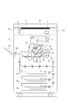
図1は本実施例を用いた画像形成装置の概略構成図である。
このシート搬送装置は、電子写真フルカラーシート搬送装置であり、上部にデジタルカラー画像リーダー部R、下部にデジタルカラー画像プリンタ部Pを有する。
FIG. 1 is a schematic configuration diagram of an image forming apparatus using the present embodiment.
This sheet conveying apparatus is an electrophotographic full color sheet conveying apparatus, and has a digital color image reader unit R in the upper part and a digital color image printer part P in the lower part.
リーダー部Rにおいて、31は原稿台ガラス、32はそのガラス31に対して開閉可能な原稿圧着板である。ガラス31上にカラー原稿Oを画像面下向きで所定の載置基準に従って載置し、その上に原稿圧着板32を被せることで原稿Oをセットする。
In the reader unit R,
原稿圧着板32を原稿自動送り装置(ADF、RDF)にして、ガラス31上にシート状原稿を自動的に送る構成にすることもできる。
33はガラス31の下面に沿って移動駆動される移動光学系である。この移動光学系33によりガラス31上の原稿Oの下向き画像面が光学的に走査される。その原稿走査光が光電変換素子(固体撮像素子)であるCCD34に結像されてRGB(レッド・グリーン・ブルー)の三原色で色分解読取りされる。
The
A moving
読取られたRGBの各信号が(図中明記しない)画像処理部に入力される。
プリンタ部Pは、1ドラム、ロータリー現像構成、及び中間転写構成を有する電子写真画像形成機構である。
The read RGB signals are input to an image processing unit (not shown in the figure).
The printer unit P is an electrophotographic image forming mechanism having one drum, a rotary development configuration, and an intermediate transfer configuration.
このプリンタ部Pの動作概略は次の通りである。
像担持体としての電子写真感光体ドラム(以下、感光ドラムという)1上に、画像信号に基づいて、レーザースキャナ2が、静電潜像を形成する。
The outline of the operation of the printer unit P is as follows.
A laser scanner 2 forms an electrostatic latent image on an electrophotographic photosensitive drum (hereinafter referred to as a photosensitive drum) 1 as an image carrier based on an image signal.
感光ドラム上に形成された静電潜像は複数の現像器により現像される。現像器は、所望の色の現像剤を収容し、(図中明記しない)トナーカートリッジ部より現像剤としてのトナーを必要時随時補給されるための補給パイプ400を備え、現像ロータリー内部に配置される。
The electrostatic latent image formed on the photosensitive drum is developed by a plurality of developing devices. The developing device contains a developer of a desired color, and includes a
この感光ドラム1上の各色のトナー像を更に中間転写ベルト51上に1色毎に1次転写することを繰り返して、中間転写ベルト51上に未定着の必要色のトナー像を形成する。その後、このトナー像を一括で記録材S上に2次転写し、次いで定着してフルカラー画像形成物を出力するものである。
The toner image of each color on the photosensitive drum 1 is further primary transferred for each color on the
以下に、更に詳しく説明する。
トナー像を担持する像担持体としての感光ドラム1は矢印の反時計方向に所定の速度で回転駆動され、その表面が帯電手段としての帯電器2により所定の極性・電位に一様に帯電される。その帯電処理面が露光手段としてのレーザースキャナ3によりレーザー走査露光される。
This will be described in more detail below.
A photosensitive drum 1 as an image carrier for carrying a toner image is rotationally driven in a counterclockwise direction indicated by an arrow at a predetermined speed, and its surface is uniformly charged to a predetermined polarity and potential by a charger 2 as a charging means. The The charged surface is subjected to laser scanning exposure by a laser scanner 3 as exposure means.
レーザースキャナ3は、レーザー出力部、ポリゴンミラー、結像レンズ、折り返しミラー等を有し、画像処理部35から入力される画像情報信号に対応して変調されたレーザー光(光信号)を出力して、回転する感光ドラム1の帯電処理面を走査露光する。これにより、感光ドラム1の面に走査露光パターンに対応した静電潜像が形成される。 The laser scanner 3 includes a laser output unit, a polygon mirror, an imaging lens, a folding mirror, and the like, and outputs a laser beam (optical signal) modulated in accordance with an image information signal input from the image processing unit 35. Then, the charged surface of the rotating photosensitive drum 1 is scanned and exposed. As a result, an electrostatic latent image corresponding to the scanning exposure pattern is formed on the surface of the photosensitive drum 1.
尚、上記画像情報信号は、前述のリーダー部Rから読み込まれた画像情報以外にも、パソコンなどの外部機器より電送される画像情報より合成、形成されたものでももちろん構わない。 In addition to the image information read from the reader unit R, the image information signal may be synthesized and formed from image information transmitted from an external device such as a personal computer.
その静電潜像がロータリー現像装置4によりトナー像として現像される。
ロータリー現像装置4は、ロータリー41に、各々の色現像剤(トナー)を収容させた複数の現像器4を装着したものである。
The electrostatic latent image is developed as a toner image by the rotary developing device 4.
The rotary developing device 4 includes a rotary 41 and a plurality of developing devices 4 each containing a color developer (toner).
ロータリー41が所定の制御タイミングにて所定の角度、図示矢印方向に回転されることによって、各々の現像器が感光ドラム1と対向する現像位置に切り換えられて配置される。現像位置において、感光ドラム1と、現像器側の現像スリーブとの距離(SD距離)がある決められた範囲内に保たれる。
When the
トナー像が転写される中間転写ベルト51は可撓性を有する誘電材製のエンドレスベルトであり、張架部材としての複数のローラ5a〜5g間に懸回張設されている。中間転写ベルト51の外面はローラ5b・5c間において感光ドラム1に接触して、1次転写ニップ部T1を形成する。
The
この1次転写ニップ部T1において、ベルト5の感光ドラム1側と反対側に1次転写ローラ6が配設されていて、中間転写ベルト51の内面に接している。
この1次転写ローラ6には、所定の制御タイミングにて、トナーと逆極性の1次転写電圧が印加される。中間転写ベルト51は、例えばローラ5aを駆動ローラとして、感光ドラム1の回転速度とほぼ同じ速度で矢印の時計方向に移動可能なベルト部材として構成される。
In the primary transfer nip T 1, a primary transfer roller 6 is disposed on the opposite side of the belt 5 from the photosensitive drum 1 side and is in contact with the inner surface of the
A primary transfer voltage having a polarity opposite to that of the toner is applied to the primary transfer roller 6 at a predetermined control timing. The
まず、感光ドラム1に対して、1色目のトナー像が、上記の帯電・露光・現像の画像形成工程により形成される。そして、その感光ドラム1上のトナー像が1次転写ニップ部T1において中間転写ベルト51上に転写される。
中間転写ベルト51に転写されないで感光ドラム1の面に残った1次転写残トナーはドラムクリーニング装置7により感光ドラム面から除去される。クリーニング装置7により清掃された感光ドラム1は繰り返して画像形成に供される。
First, a toner image of the first color is formed on the photosensitive drum 1 by the above-described image forming process of charging / exposure / development. Then, the toner image on the photosensitive drum 1 is transferred onto the
The primary transfer residual toner that is not transferred to the
上記と同様の画像形成工程が、2色目〜N色目について、同様に随時繰り返される。これにより、中間転写ベルト51上に、各現像色のトナー像の順次重畳転写からなる未定着のトナー画像が合成形成される。
The same image forming process as described above is repeated as necessary for the second to Nth colors. As a result, an unfixed toner image is formed and synthesized on the
一方、所定の制御タイミングで、第1〜第3の給紙カセット81〜83の複数の給紙部のうち、予め選択された給紙部の給紙ローラ11が駆動される。これにより、その給紙部に収容された記録材Sが1枚分離されて送り出され、シートパス13からレジストローラ対14へ送られる。
On the other hand, the
レジストローラ14対は、記録材Sの斜行補正と、中間転写ベルト51から記録材Sへのトナー像の2次転写のタイミングを制御するもので、給紙部側から給紙された記録材Sの先端を受け止めて一旦停止させる。
The pair of
15は2次転写ローラである。2次転写ローラ15は、中間転写ベルト51を付勢する複数のローラ5a〜5gの内、ローラ5g(対向ローラ)に対向する。2次転写ローラ15は、対向ローラ5gに対してベルト5を挟んで所定に圧接した第1状態と、中間転写ベルト51の外面から離間した第2状態とに、(図中明記しない)加圧制御機構により切り換えられて、脱着制御される。
Reference numeral 15 denotes a secondary transfer roller. The secondary transfer roller 15 faces the roller 5g (opposing roller) among the plurality of rollers 5a to 5g that urge the
2次転写ローラ15は常時は中間転写ベルト51の外面から離間した第2状態に切り換えられて保持されている。尚、第1状態に切り換えられることで、中間転写ベルト51の外面との間に2次転写ニップ部T2が形成される。
The secondary transfer roller 15 is always switched and held in the second state separated from the outer surface of the
2次転写ローラ15は所定の制御タイミングで第1状態に切り変えられる。また、レジストローラ対14の位置で一旦停止されている記録材Sは所定の制御タイミングでレジストローラ対14から再給紙され、第1状態に切り変えられた2次転写ローラ15と中間転写ベルト51との間の2次転写ニップ部T2に導入される。
The secondary transfer roller 15 is switched to the first state at a predetermined control timing. In addition, the recording material S that has been temporarily stopped at the position of the
そして、記録材Sはこの2次転写ニップ部T2を挟持搬送されていく。その間、2次転写ローラ15には所定の2次転写電圧が印加されて、中間転写ベルト51上の複数色からなるトナー像が記録材S上に静電的に一括転写され、記録材S上には未定着のトナー像が形成(転写)される。
The recording material S is nipped and conveyed through the secondary transfer nip portion T2. In the meantime, a predetermined secondary transfer voltage is applied to the secondary transfer roller 15, and a toner image composed of a plurality of colors on the
記録材Sに転写されないで中間転写ベルト51上に残った2次転写残トナーはベルトクリーニング装置16により中間転写ベルト表面から除去される。このクリーニング装置16により清掃された中間転写ベルト51は繰り返して画像形成に供される。
The secondary transfer residual toner not transferred to the recording material S and remaining on the
クリーニング装置16は、常時は中間転写ベルト51の外面から離間した状態に保持されている。2次転写ニップ部T2にて中間転写ベルト51から記録材Sに対するトナー像の2次転写がなされるときに、所定の制御タイミングにて中間転写ベルト51の外面に接触した状態に切り換えられる。
The
2次転写ニップ部T2を出た記録材Sは中間転写ベルト51の面から分離して、搬送ベルトユニット17によって定着器18へ搬送され、未定着トナー像は熱及び圧力により記録材S上に融着されて定着画像となる。定着器18を出た記録材Sはシート搬送パス19を通って排紙トレイ20上に排出される。
The recording material S that has exited the secondary transfer nip T2 is separated from the surface of the
[中間転写ユニットの構成]
次に、本実施の形態の中間転写ベルト51を備える中間転写ベルトユニット50の構成について詳細に述べる。
[Configuration of intermediate transfer unit]
Next, the configuration of the intermediate
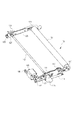
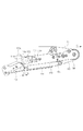
中間転写ベルト51は移動中に、移動方向に直交する幅方向に寄るおそれがある。そこで本実施形態では、中間転写ベルトの幅方向の寄りを抑制するために、中間転写ベルトを幅方向にステアリングするステアリングローラ5dが設けられている。本実施形態の中間転写ユニットの構成について図2から図5を用いて説明する。
The
5dは、中間転写ベルトを張架して、中間転写ベルトを幅方向にステアリングするステアリングローラである。115、125はステアリングローラ5dの幅方向における前側、後側の端部においてステアリングローラ5dの軸を回転可能に支持する軸受ホルダである。
前側の軸受ホルダ115は、前側のスライドレール116上をスライド可能なスライド113に対して固定されて、スライド可能に構成される。同様に後側の軸受ホルダ125は、後側のスライドレール116上をスライド可能なスライド123に対して固定されて、スライド可能に構成される。
The
前側のスライドレール116は、図4に示されるように前側に設けられたステアリングアーム101に固定される。後側のスライドレール126は、図5に示されるように中間転写ベルトユニット50の筐体をなす後側板132に固定されている。すなわち、前側のスライダ113はステアリングアーム101上をスライド可能に構成されて、後側のスライダ123は後側板132上をスライド可能に構成される。
The
なお、前側のスライダ113はステアリングアーム101にかけられたバネ114によって矢印G向きに付勢され、後側のスライダ123は後側板132にかけられたバネ124によって矢印G向きに付勢される。すなわちステアリングローラ5dは中間転写ベルト51の内周面にテンションを与えるテンションローラとして機能する。
The
ステアリングアーム101は回動軸112の周りを回動可能に構成される。回動カム103はステアリングローラ5dを回動するための回転可能なカムである。102は、ステアリングアーム101に設けられて、回動カム103に当接する当接部としてのカムフォロアである。なおカムフォロア102は、回動軸112に対してステアリングローラ5dが配置される側とは反対側に配置される。104は、カム103を駆動する駆動源としてのステアリングモータである。すなわち軸受けホルダ115、スライダ113、スライドレール116、ステアリングアーム101等はステアリングローラ5dを回動可能に支持する支持手段として構成する。
The
(ステアリングによる中間転写ベルトの寄り補正)
回動カム103が図3中矢印A方向に回動すると、ステアリングアーム101のカムフォロア102が設けられた側は回動軸112を中心に矢印C方向に回動する。この結果ステアリングアームのステアリングローラ5dが設けられた側が矢印E方向に回動することにより、中間転写ベルト51は奥側に移動する。これとは逆に回動カム103が矢印B方向に回動すると、ステアリングアーム101のカムフォロア102が設けられた側は回動軸112を中心に矢印D方向に回動する。この結果ステアリングローラ5d側が矢印F方向に回動することにより、中間転写ベルト51は前側に移動する。
(Intermediate transfer belt offset correction by steering)
When the
ところでステアリングモータ104の回動カム103が設けられている側とは反対側の出力軸上には、ホームポジションフラグ105が設けられている。ホームポジションフラグ105の位相をホームポジションセンサ106で検知することにより、回動カム103の位相を検出することが可能となっている。
Incidentally, a
本実施形態では図中明記しないベルトエッジ検出センサが中間転写ベルト51の幅方向におけるエッジ部の位置を検出する。その上で検出した位置情報を元にステアリングモータ104が回転し、ステアリングローラ5dのアライメントを変化させることによって中間転写ベルト51の寄り補正を行っている。
In the present embodiment, a belt edge detection sensor not explicitly shown in the drawing detects the position of the edge portion in the width direction of the
(テンションを解除する構成)
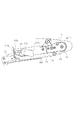
ところで中間転写ベルト51を交換する作業性を確保する場合には中間転写ベルト51のテンションを下げるのが望ましい。本実施形態における中間転写ベルト51のテンションを解除する解除機構について図2,図6、図7を用いて説明する。
(Configuration to release tension)
By the way, when ensuring the workability of replacing the
回動軸112は、前側板131と後側板132との間に回動可能に支持されていて、前側板131の外側にステアリングアーム101を回動可能に支持している。回動軸112の前側端部には解除カム111が固定され、奥側端部には解除カム121が固定されていて、解除カム111に設けられたレバー111cを回すことによって、一体的に回動可能に構成されている。
The
図6及び図7は、解除カム111の動作を説明する断面図であって、図6は加圧状態を、図7は解除状態を示している。
図7の解除状態において、解除カム111の上死点111aがスライダ113のフォロア面113aに突き当たっており、バネ114に抗してスライダ113を矢印Hの方向に寄せている。この結果、軸受ホルダ115は矢印Hの方向に移動し、中間転写ベルト51のテンションが解除される。このとき、奥側の解除カム121も回動軸112によって連動して回動しており、解除カム111と同様に動作する。
6 and 7 are sectional views for explaining the operation of the
In the released state of FIG. 7, the top
定期交換等により中間転写ベルト51を取り外す際には、上述した位置まで解除カム111を回動させてテンションを解除し、軸方向に中間転写ベルト51をスライドさせてユニットから抜き去る。ここで、前側板131は、その投影面積が中間転写ベルト51の断面積よりも小さく構成されており、中間転写ベルト51を手前側に抜き去ることができるようになっている。
When removing the
一方、解除111を時計回りに回転させると、スライダ113のフォロア面113aに突き当たる位相は上死点111aから下死点111bへと徐々に移行していく。これに従い、スライダ113はバネ114に引っ張られて矢印G方向に移動し、中間転写ベルト51に対し徐々にテンションが与えられていく。そして、下死点111bの位相に到達した時に所望のテンションが与えられ、図6に示した状態に至り、前述した画像形成動作に供されるようになる。ここで実際には、中間転写ベルト51の長さによりステアリングローラ5dの矢印G方向への移動量が規制され、下死点111bはフォロア面113aには突き当たらずにクリアランスWを有した状態でテンションが与えられるようになる。
On the other hand, when the
[カムの規制部について]
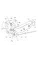
次に、本実施の形態の特徴的な構成について述べる。
図8は回動カム103の設置部を拡大した図である。本実施形態では回動カム103には、カムフォロア102に当接するためのカムプロファイルが形成される。
[Cam control section]
Next, a characteristic configuration of the present embodiment will be described.
FIG. 8 is an enlarged view of the installation portion of the
回動カム103のカムプロファイルには、ステアリングローラ5dのアライメントが変化しない中立点103bが設けられる。通常の画像形成動作中は、中立点103bを中心として回動軸112周りの位相が±5deg程度になる範囲が用いられる。すなわちこの範囲が回動カム103の画像形成に使用される領域として機能する。その結果画像形成動作中に走行中の中間転写ベルト51の幅方向の寄りが抑制される。
The cam profile of the
さらに回動カム103のカムプロファイルは、回動カム103には回転軸からの距離が最大となる上死点103aから回転軸からの距離が最小となる下死点103cにかけて、回転軸1041からの距離が単調減少するように形成される。すなわち上死点103aは回転軸を中心とするカムの半径が最大となる最大部であり、下死点103cは回転軸を中心とするカムの半径が最小となる最小部である。その上でステアリングローラ5dの自重がカムフォロア102を回動カム103に突き当てる向きにかかるように構成される。その結果、ステアリングローラ5dの自重によって、回動カム103を回転させる回転モーメントが矢印A向きに働く。その結果画像形成装置本体のスタンバイ時や電源OFF時にステアリングモータ104の回動カム103に対する駆動力の供給が停止すれば、回動カム103が矢印A向きにカムフォロア102が下死点103cに向けて自動的に回動する。
Further, the cam profile of the
本実施形態では図8に示されるように、カムフォロア102が回動カム103の下死点103cに当接するとカムフォロア102がA向きにさらに回動するのを規制するために、回動規制部103e(第2の規制部)が設けられている。回動規制部103eは、カムフォロア102が回動カム103の下死点103cに当接した状態でカムフォロア102の円周の半分と嵌合する形状である。回動カム103の下死点103c及び回動規制部103eはカムプロファイルの画像形成に使用されない領域に形成されているので、カムフォロアの回動は画像形成に使用されない領域で自動的に停止する。
In the present embodiment, as shown in FIG. 8, when the
さらに本実施形態では、カムフォロア102が回動カム103の下死点103cに当接するとカムフォロア102が回動カムから離間する向きに動くのを規制するための離間規制部103d(第1の規制部)が設けられている。L1は、回動カム102の回転軸1041の中心と下死点103cとを結ぶ直線を示す。下死転103cに当接したカムフォロア102が回動カムから離間する向きはL1の方向であるので、離間規制部103dは、直線L1上を回転軸1041から下死点103cに向かう向きにおいて、下死点103cよりもさらに先に進んだ位置に設けられる。
Furthermore, in this embodiment, when the
離間規制部103dを設ける理由について説明する。中間転写ベルトの交換を行う際にステアリングアーム101が誤って押された場合に、ステアリングローラ5dのカムフォロア102が回動カム103から離間するおそれがある。そうするとカムフォロア102が回動カム103から瞬間的に離間した後に突き当たる方向に戻る際に回動カムや駆動源にショックを与えるおそれがある。すなわちステアリングローラの自重によりカムフォロアがカムを押し込んで停止した位置で、ステアリングアームのカムフォロアがカムから離間する向きに動くのを規制するのが望ましい。
The reason for providing the
さらに本実施形態では、カムフォロア103が下死点に到達して回動規制部103eにより回動が規制された状態で、カムフォロア102が離間規制部103dにL1上で接触するように、離間規制部103dと下死点103cとの間隔が設定される。その結果停止した状態のカムフォロア103dが離間するのが効果的に抑制される。
Furthermore, in the present embodiment, the separation restricting portion is arranged so that the
なお本実施形態ではカムフォロア102が下死転103cに到達すると離間規制部103dに直線L1上で接触する構成であるが、この構成に限定する意図ではない。カムフォロア102が下死点103cに到達した状態で、カムフォロア102と離間規制部103aとの間に若干のギャップ(クリアランス)を設けてもよい。その場合にはギャップの大きさは、ステアリングアーム101の回動運動の可動域に比べ小さい値にする必要がある。
In the present embodiment, when the
なお本実施形態ではステアリングローラ104の駆動を停止すれば回動カム103が下死点103cまで自動的に移動する構成であるが、この実施形態に限定する意図ではない。回動カム103のカムプロファイルがなだらかな構成では、ステアリングモータ104の駆動を切ってもカムフォロア102が回動カム103の下死点103cに位置しない場合がある。この場合、ユーザーからの画像形成装置本体のスタンバイや電源OFFに入る信号を受けた後に、ホームポジションフラグ105の位相をホームポジションセンサ106で検知する。その上で回動カム103を下死点103cの位置まで回動させ、その後にスタンバイや電源OFF状態になるようなシーケンスを追加することも可能である。
In the present embodiment, the
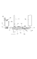
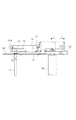
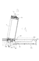
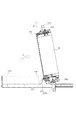
(中間転写ベルト51の交換)
図9は中間転写ベルトユニット50を画像形成装置本体から引き出した状態を示す上面図である。中間転写ベルト51を交換する際には、画像形成装置本体に設置された状態(図9中破線部)から解除カム111に設けられたレバー111cを図9中矢印J方向へ引くことにより、画像形成装置本体より引き出すことが可能である。このとき、画像形成装置本体に設置されたスライドレール左107e、右107fが図9中手前方向に延長し、スライドレール左107e、右107fに固定された中間転写ベルトフレーム手前107a、左107b、右107c、奥107dが共に引き出される。中間転写ベルトユニット50は中間転写ベルトフレーム(107a、107b、107c、107d)と共に引き出される。この際、手前側では解除カム111が中間転写ベルトフレーム手前107aに支持される。一方で奥側では中間転写ベルトユニット回動軸左109aが中間転写ベルトフレーム左107bに、中間転写ベルトユニット回動軸右109bが中間転写ベルトフレーム右にそれぞれ回動可能に支持される。さらに中間転写ベルトフレーム右107c上には、後述する中間転写ベルトユニット50を跳ね上げる動作の後に中間転写ベルトユニットを固定するための固定軸108が載置されている。
(Replacing the intermediate transfer belt 51)
FIG. 9 is a top view showing a state in which the intermediate
図10は、中間転写ベルトユニット50を画像形成装置本体から引き出し、中間転写ベルト51を交換するために跳ね上げる動作を行った後の状態を示す左視図であり、図11は、同右視図である。図10中破線部から、解除カム111に設けられたレバー111cを保持して図中矢印K方向へ引く。そうすることで中間転写ベルトユニット回動軸左109a、中間転写ベルトユニット回動軸右109bを回動中心として中間転写ベルトユニット50を跳ね上げることが可能である。中間転写ベルトユニット50を跳ね上げた後、レバー111cを保持したまま、固定軸108を中間転写ベルトフレーム右107から取り外し、中間転写ベルトフレーム奥107dに設けられた固定軸固定部1071、1072に設置する。固定軸108が後側板132を支持することにより中間転写ベルトユニット50は自立する。
FIG. 10 is a left side view showing a state after the intermediate
中間転写ベルトユニット50を自立させたまま、前述の中間転写ベルトテンション解除動作を行うことにより、中間転写ベルト51は図10、図11中矢印N方向へ引き抜き可能となる。なお、図10、図11に示す中間転写ベルトユニット50の自立状態において中間転写ベルト51の交換作業当でステアリングローラ5d等に外力が加わっても、ステアリングアーム101が回動することは無く、ベルト破損防止、サービス性の向上が可能となる。
The
上述した実施の形態においては、中間転写ベルトユニット50を例にとって説明したが、感光体ベルトや転写ベルト、定着ベルト体においても同様の構成を適用することが可能であり、この場合も同様の効果を奏することができる。
In the above-described embodiment, the intermediate
51 中間転写ベルト
5d ステアリングローラ
101 ステアリングアーム
102 カムフォロア
103 回動カム
104 ステアリングモータ
105 ホームポジションフラグ
108 固定軸
109a、109b 中間転写ベルトユニット回動軸
111、121 解除カム
112 回動軸
114、124 バネ(付勢部材)
115,125 軸受ホルダ(スライド部材)
131 前側板
132 後側板
51
115,125 Bearing holder (slide member)
131
Claims (6)
前記ベルト部材を張架する張架部材と、
前記ベルト部材を張架して、前記ベルト部材を幅方向にステアリングするステアリングローラと、
前記ステアリングローラを回転可能に支持する支持手段と、
画像形成に使用される領域と、画像形成に使用されない領域とを備えて、前記支持手段を回動させるために回転可能なカムと、
前記支持手段に設けられて前記カムに当接する当接部と、
前記カムの回転を駆動する駆動源とを備える画像形成装置において、
前記カムの画像形成に使用されない領域に設けられて、前記当接部が前記カムから離間する方向に動くのを規制する規制部を備えることを特徴とする画像形成装置。 A movable belt member;
A tension member that stretches the belt member;
A steering roller that stretches the belt member and steers the belt member in the width direction;
Support means for rotatably supporting the steering roller;
A cam that includes a region that is used for image formation and a region that is not used for image formation, and is rotatable to rotate the support means;
A contact portion provided on the support means and contacting the cam;
An image forming apparatus comprising a drive source for driving rotation of the cam;
An image forming apparatus comprising: a restricting portion that is provided in an area not used for image formation of the cam and restricts the contact portion from moving in a direction away from the cam.
前記カムの画像形成に使用されない領域に設けられて、前記当接部に接触して前記カムが回動するのを規制する第2の規制部を備えることを特徴とする請求項1乃至3のいずれかに記載された画像形成装置。 The restriction part is a first restriction part,
4. A second restricting portion that is provided in an area not used for image formation of the cam and that restricts rotation of the cam in contact with the contact portion. An image forming apparatus described in any one of the above.
The first restricting portion is configured so that the abutting portion also contacts the first restricting portion in a state where the abutting portion is in contact with the second restricting portion of the cam. The image forming apparatus according to claim 4, wherein:
Priority Applications (1)
| Application Number | Priority Date | Filing Date | Title |
|---|---|---|---|
| JP2011111680A JP2012242554A (en) | 2011-05-18 | 2011-05-18 | Image forming apparatus |
Applications Claiming Priority (1)
| Application Number | Priority Date | Filing Date | Title |
|---|---|---|---|
| JP2011111680A JP2012242554A (en) | 2011-05-18 | 2011-05-18 | Image forming apparatus |
Publications (1)
| Publication Number | Publication Date |
|---|---|
| JP2012242554A true JP2012242554A (en) | 2012-12-10 |
Family
ID=47464342
Family Applications (1)
| Application Number | Title | Priority Date | Filing Date |
|---|---|---|---|
| JP2011111680A Withdrawn JP2012242554A (en) | 2011-05-18 | 2011-05-18 | Image forming apparatus |
Country Status (1)
| Country | Link |
|---|---|
| JP (1) | JP2012242554A (en) |
Cited By (2)
| Publication number | Priority date | Publication date | Assignee | Title |
|---|---|---|---|---|
| JP2018022176A (en) * | 2017-09-21 | 2018-02-08 | キヤノン株式会社 | Belt conveying device and image forming apparatus |
| JP2018146849A (en) * | 2017-03-07 | 2018-09-20 | キヤノン株式会社 | Belt conveyance apparatus and image forming apparatus |
-
2011
- 2011-05-18 JP JP2011111680A patent/JP2012242554A/en not_active Withdrawn
Cited By (3)
| Publication number | Priority date | Publication date | Assignee | Title |
|---|---|---|---|---|
| JP2018146849A (en) * | 2017-03-07 | 2018-09-20 | キヤノン株式会社 | Belt conveyance apparatus and image forming apparatus |
| US10947072B2 (en) | 2017-03-07 | 2021-03-16 | Canon Kabushiki Kaisha | Belt conveying device and image forming apparatus |
| JP2018022176A (en) * | 2017-09-21 | 2018-02-08 | キヤノン株式会社 | Belt conveying device and image forming apparatus |
Similar Documents
| Publication | Publication Date | Title |
|---|---|---|
| JP5522510B2 (en) | Transfer device and image forming apparatus equipped with the transfer device | |
| US8335448B2 (en) | Conveyance unit and image forming apparatus comprising the same | |
| US8867961B2 (en) | Image forming apparatus capable of preventing belt from meandering | |
| US9213272B2 (en) | Image forming apparatus including a holding member to hold a roller relative to a frame | |
| US11474457B2 (en) | Image forming apparatus that can selectively switch between two transfer rollers | |
| US11543763B2 (en) | Transfer unit capable of switching between two transfer rollers | |
| JP2002244359A (en) | Image forming apparatus and image forming method | |
| JP3968238B2 (en) | Image forming apparatus | |
| US11520256B2 (en) | Transfer unit capable of switching between a plurality of transfer rollers | |
| US11520254B2 (en) | Transfer unit capable of switching between two transfer rollers and maintaining a positional relationship with pre-transfer guide | |
| US20220236669A1 (en) | Transfer unit and image forming apparatus therewith | |
| JP2009237080A (en) | Endless member drive apparatus and image forming apparatus | |
| US20090304429A1 (en) | Image forming apparatus | |
| JP2009258564A (en) | Endless member driving device and image forming apparatus | |
| JP5398135B2 (en) | Image forming apparatus | |
| JP2005043863A (en) | Image forming apparatus | |
| JP2012242554A (en) | Image forming apparatus | |
| US20240142898A1 (en) | Image forming device | |
| JPH11295961A (en) | Multicolor image forming device | |
| JP2013076863A (en) | Belt conveyance device and image forming apparatus | |
| JP5811441B2 (en) | Image forming apparatus and transfer unit | |
| CN116610015A (en) | Transfer unit and image forming apparatus including the transfer unit | |
| JP2011123112A (en) | Image forming apparatus | |
| JP5349262B2 (en) | Intermediate transfer belt conveying device, image forming apparatus and image forming method using the same | |
| JP4387246B2 (en) | Color image forming apparatus |
Legal Events
| Date | Code | Title | Description |
|---|---|---|---|
| A300 | Withdrawal of application because of no request for examination |
Free format text: JAPANESE INTERMEDIATE CODE: A300 Effective date: 20140805 |