JP2009258564A - Endless member driving device and image forming apparatus - Google Patents
Endless member driving device and image forming apparatus Download PDFInfo
- Publication number
- JP2009258564A JP2009258564A JP2008110407A JP2008110407A JP2009258564A JP 2009258564 A JP2009258564 A JP 2009258564A JP 2008110407 A JP2008110407 A JP 2008110407A JP 2008110407 A JP2008110407 A JP 2008110407A JP 2009258564 A JP2009258564 A JP 2009258564A
- Authority
- JP
- Japan
- Prior art keywords
- endless
- rotation
- belt
- deviation
- endless member
- Prior art date
- Legal status (The legal status is an assumption and is not a legal conclusion. Google has not performed a legal analysis and makes no representation as to the accuracy of the status listed.)
- Pending
Links
- 230000008859 change Effects 0.000 claims abstract description 10
- 238000012546 transfer Methods 0.000 claims description 91
- 238000001514 detection method Methods 0.000 claims description 62
- 238000006073 displacement reaction Methods 0.000 claims description 19
- 230000005540 biological transmission Effects 0.000 claims description 13
- 230000002093 peripheral effect Effects 0.000 claims description 10
- 230000001105 regulatory effect Effects 0.000 claims description 2
- 239000002609 medium Substances 0.000 description 133
- 238000010586 diagram Methods 0.000 description 34
- 108091008695 photoreceptors Proteins 0.000 description 18
- 238000012937 correction Methods 0.000 description 17
- 238000000034 method Methods 0.000 description 12
- 239000011521 glass Substances 0.000 description 6
- 230000008569 process Effects 0.000 description 5
- 238000012545 processing Methods 0.000 description 5
- 239000003086 colorant Substances 0.000 description 4
- 238000010438 heat treatment Methods 0.000 description 4
- 239000000463 material Substances 0.000 description 4
- 238000012423 maintenance Methods 0.000 description 3
- 239000011324 bead Substances 0.000 description 2
- 238000004140 cleaning Methods 0.000 description 2
- 238000010276 construction Methods 0.000 description 2
- 238000003384 imaging method Methods 0.000 description 2
- 238000006386 neutralization reaction Methods 0.000 description 2
- 230000003287 optical effect Effects 0.000 description 2
- 230000002265 prevention Effects 0.000 description 2
- 238000009751 slip forming Methods 0.000 description 2
- 230000015572 biosynthetic process Effects 0.000 description 1
- 230000006866 deterioration Effects 0.000 description 1
- 230000005684 electric field Effects 0.000 description 1
- 239000012526 feed medium Substances 0.000 description 1
- 230000006872 improvement Effects 0.000 description 1
- 238000012986 modification Methods 0.000 description 1
- 230000004048 modification Effects 0.000 description 1
- 230000003472 neutralizing effect Effects 0.000 description 1
- 239000002699 waste material Substances 0.000 description 1
Images


Landscapes
- Electrostatic Charge, Transfer And Separation In Electrography (AREA)
Abstract
Description
本発明は、無端状部材駆動装置および画像形成装置に関する。 The present invention relates to an endless member driving device and an image forming apparatus.
従来の無端状部材を備えた画像形成装置に関する技術として、下記の特許文献1〜3記載の技術が知られている。
特許文献1としての特開2006−162659号公報には、アイドルローラ(53)の端部に転写ベルト(51)のビード(58)が接触するプーリ(57)が回転可能に支持され、アイドルローラ(53)の回転軸を支持し且つプーリ(57)と接触する傾斜可能なローラ傾動レバー(64)を設けた構成において、転写ベルト(51)が片寄ると、プーリ(57)がビード(58)に押されて、接触するローラ傾動レバー(64)が傾斜することで、アイドルローラ(53)が転写ベルト(51)の片寄りを打ち消す方向に傾斜する技術が記載されている。すなわち、軸に対して傾斜可能でプーリ(57)に接触する複雑な形状のローラ傾動レバー(64)を使用して、転写ベルト(51)の蛇行を防止している。
As techniques related to a conventional image forming apparatus provided with an endless member, techniques described in
In Japanese Patent Application Laid-Open No. 2006-162659 as
特許文献2としての特開平4−121337号公報には、感光体ベルト(4)を支持する第3ローラ部材(3)の軸方向端部に、外側に行くほど外形が大きくなるテーパ面(11a)を有する蛇行検出部材(11)が配置されており、感光体ベルト(4)に蛇行が発生すると、その蛇行変位により感光体ベルト(4)が蛇行検出部材(11)に乗り上げることで、蛇行を検出する技術が記載されている。また、特許文献2記載の技術では、蛇行検出部材(11)に感光体ベルト4が乗り上げて蛇行検出部材(11)に回転トルクが作用すると、蛇行検出部材(11)が回転し、蛇行検出部材(11)に連結された紐部材(13)が巻き取られたりすることで、第3ローラ部材(3)の軸の位置を変位させ、蛇行を打ち消している。すなわち、ベルトがテーパ面を有する蛇行検出部材に乗り上げて回転すると、蛇行が検出されて片寄りを補正する方向に軸が傾斜すると共に、紐部材(13)が限界まで伸びると回転の抵抗になる構成が記載されている。
Japanese Patent Laid-Open No. 4-121337 as
特許文献3としての特開平6−56294号公報には、転写材搬送ベルト(11)の蛇行を防止するために、ベルト位置センサで検出したベルト位置に基づいて、モータ(51)を駆動させて、カム(48,49)を回転させることで、転写材搬送ベルト(11)を支持する張力付与ロール(14)を傾斜させて、片寄りを補正する技術が記載されている。
In JP-A-6-56294 as
本発明は、簡素な構成で無端状部材の片寄りを防止することを技術的課題とする。 An object of the present invention is to prevent the endless member from being displaced with a simple configuration.
前記技術的課題を解決するために、請求項1に記載の発明の無端状部材駆動装置は、
駆動力を受けて回転し表裏平面状で無端状の無端状部材と、
前記無端状部材を支持する回転支持部材と、
前記回転支持部材の軸方向端部に回転可能に支持された片寄り検知部材と、
前記回転支持部材の軸方向端部に回転可能に支持され且つ、前記無端状部材が前記回転軸の軸方向端部に片寄って前記片寄り検知部材が前記無端状部材から力を受けた場合に前記片寄り検知部材の回転に基づいて回転可能な軸位置変移部材であって、前記回転支持部材の回転軸に対する径方向外端までの長さが変化する外周面を有し、基準面に前記外周面が接触して前記無端状部材の片寄りを補正する方向に前記回転支持部材の回転軸の位置を変移させる軸位置変移部材と、
を備えたことを特徴とする。
In order to solve the technical problem, an endless member driving device according to
An endless member that is rotated by receiving a driving force and is endless in a planar shape on the front and back sides,
A rotation support member for supporting the endless member;
A deviation detection member rotatably supported at an axial end of the rotation support member;
When the endless member is supported rotatably at the axial end of the rotation support member and the offset detecting member receives a force from the endless member due to the axial end of the rotation shaft being offset. The shaft position changing member is rotatable based on the rotation of the deviation detecting member, and has an outer peripheral surface in which a length to a radially outer end with respect to a rotation axis of the rotation support member changes, An axial position shifting member that shifts the position of the rotation shaft of the rotation support member in a direction in which an outer peripheral surface comes into contact and corrects a deviation of the endless member;
It is provided with.
請求項2に記載の発明は、請求項1に記載の無端状部材駆動装置において、
前記片寄り検知部材と前記軸位置変移部材との間に配置され且つ、前記片寄り検知部材が前記無端状部材から受ける力が予め設定された所定の値よりも小さい場合に、前記片寄り検知部材と前記軸位置変移部材とが連れ回りし、前記所定の値よりも大きい場合に、前記片寄り検知部材のみが回転するように、回転が伝達することを規制する回転伝達規制部材、
を備えたことを特徴とする。
The invention according to
The displacement detection is performed when the displacement detection member is disposed between the displacement detection member and the shaft position change member and the force received by the displacement detection member from the endless member is smaller than a predetermined value set in advance. A rotation transmission restricting member for restricting transmission of rotation so that only the deviation detecting member rotates when the member and the shaft position shifting member rotate together and are larger than the predetermined value;
It is provided with.
請求項3に記載の発明は、請求項1に記載の無端状部材駆動装置において、
前記片寄り検知部材と前記軸位置変移部材との間に配置され且つ、前記片寄り検知部材が前記無端状部材から受ける力の変動にあわせて、前記軸位置変移部材の回転量を変化させるバネ状の回転伝達規制部材、
を備えたことを特徴とする。
According to a third aspect of the present invention, in the endless member driving device according to the first aspect,
A spring that is disposed between the offset detecting member and the shaft position changing member and that changes the amount of rotation of the shaft position changing member in accordance with a change in force that the offset detecting member receives from the endless member. Shaped rotation transmission regulating member,
It is provided with.
請求項4に記載の発明は、請求項1ないし3のいずれかに記載の無端状部材駆動装置において、
偏心カムにより構成された前記軸位置変移部材、
を備えたことを特徴とする。
The invention according to
The shaft position changing member constituted by an eccentric cam;
It is provided with.
請求項5に記載の発明は、請求項1ないし4のいずれかに記載の無端状部材駆動装置において、
前記軸位置変位部材を回転させるのに、無端状部材の回転力または、無端状部材の軸方向への移動力を利用することを特徴とする。
The invention according to
In order to rotate the axial position displacement member, the rotational force of the endless member or the moving force of the endless member in the axial direction is used.
請求項6に記載の発明は、請求項1ないし4のいずれかに記載の無端状部材駆動装置において、
無端状部材の片寄り量に応じて、前記軸変位部材を回転させることを特徴とする。
The invention according to
The shaft displacement member is rotated according to a deviation amount of the endless member.
前記技術的課題を解決するために、請求項7に記載の発明の画像形成装置は、
媒体を帯状の無端状部材表面に保持して搬送する媒体搬送装置により構成された請求項1ないし6のいずれかに記載の無端状部材駆動装置と、
前記媒体に可視像を形成する可視像形成装置と、
を備えたことを特徴とする。
In order to solve the technical problem, an image forming apparatus according to
The endless member driving device according to any one of
A visible image forming apparatus for forming a visible image on the medium;
It is provided with.
前記技術的課題を解決するために、請求項8に記載の発明の画像形成装置は、
可視像を形成させる可視像形成装置と、
前記可視像形成装置で形成された可視像を前記帯状の無端状部材により構成された中間転写体表面に転写させる一次転写器と、
前記中間転写体を備えた中間転写体駆動装置により構成された請求項1ないし6のいずれかに記載の無端状部材駆動装置と、
前記中間転写体表面の可視像を媒体に二次転写させる二次転写器と、
を備えたことを特徴とする。
In order to solve the technical problem, an image forming apparatus according to
A visible image forming apparatus for forming a visible image;
A primary transfer device for transferring a visible image formed by the visible image forming apparatus to the surface of an intermediate transfer member constituted by the band-shaped endless member;
An endless member driving device according to any one of
A secondary transfer device for secondary transfer of the visible image on the surface of the intermediate transfer member to a medium;
It is provided with.
請求項1に記載の発明によれば、本発明の構成を有しない場合に比べて、簡素な構成で無端状部材の片寄りを防止することができる。
請求項2に記載の発明によれば、片寄り検知部材が無端状部材に従動回転でき、本発明の構成を有しない場合に比べて、片寄り検知部材や無端状部材の摩耗や擦れる音の発生を低減することができる。
請求項3および請求項4に記載の発明によれば、本発明の構成を有しない場合に比べて、容易に作成することができる。
According to the first aspect of the present invention, it is possible to prevent the endless member from being displaced with a simple configuration as compared with the case where the configuration of the present invention is not provided.
According to the second aspect of the present invention, the deviation detection member can be driven and rotated by the endless member, and compared with the case where the deviation detection member or the endless member is not configured, the deviation detection member and the endless member are less worn. Generation can be reduced.
According to the invention of
請求項5および請求項6に記載の発明によれば、本発明の構成を有しない場合に比べて、構成を簡素化することができる。
請求項7記載の発明によれば、本発明の構成を有しない場合に比べて、簡素な構成で媒体を搬送する無端状部材の片寄りを防止することができる。
請求項8に記載の発明によれば、本発明の構成を有しない場合に比べて、簡素な構成で中間転写体の片寄りを防止することができる。
According to the fifth and sixth aspects of the invention, the configuration can be simplified as compared with the case where the configuration of the present invention is not provided.
According to the seventh aspect of the present invention, it is possible to prevent a deviation of the endless member that conveys the medium with a simple configuration as compared with the case where the configuration of the present invention is not provided.
According to the eighth aspect of the invention, it is possible to prevent the intermediate transfer member from being displaced with a simple configuration as compared with the case where the configuration of the present invention is not provided.
次に図面を参照しながら、本発明の実施の形態の具体例(以下、実施例と記載する)を説明するが、本発明は以下の実施例に限定されるものではない。
なお、以後の説明の理解を容易にするために、図面において、前後方向をX軸方向、左方向をY軸方向、上下方向をZ軸方向とし、矢印X,−X,Y,−Y,Z,−Zで示す方向または示す側をそれぞれ、前方、後方、右方、左方、上方、下方、または、前側、後側、右側、左側、上側、下側とする。
また、図中、「○」の中に「・」が記載されたものは紙面の裏から表に向かう矢印を意味し、「○」の中に「×」が記載されたものは紙面の表から裏に向かう矢印を意味するものとする。
なお、以下の図面を使用した説明において、理解の容易のために説明に必要な部材以外の図示は適宜省略されている。
Next, specific examples of embodiments of the present invention (hereinafter referred to as examples) will be described with reference to the drawings, but the present invention is not limited to the following examples.
In order to facilitate understanding of the following description, in the drawings, the front-rear direction is the X-axis direction, the left direction is the Y-axis direction, the up-down direction is the Z-axis direction, and arrows X, -X, Y, -Y, The direction indicated by Z and -Z or the indicated side is defined as the front side, the rear side, the right side, the left side, the upper side, the lower side, or the front side, the rear side, the right side, the left side, the upper side, and the lower side, respectively.
In the figure, “•” in “○” means an arrow heading from the back of the page to the front, and “×” in “○” is the front of the page. It means an arrow pointing from the back to the back.
In the following description using the drawings, illustrations other than members necessary for the description are omitted as appropriate for easy understanding.
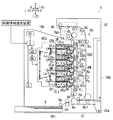
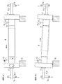
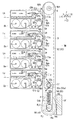
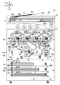
図1は本発明の実施例1の画像形成装置の全体説明図である。
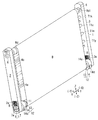
図2は本発明の実施例1のベルトモジュールの要部拡大斜視図である。
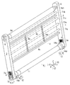
図3は図2のベルトモジュールにおいて媒体搬送ベルトを取り外した状態の説明図である。
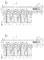
図4はプリンタの要部説明図であり、図4Aは媒体搬送ベルトが回転していない状態の要部説明図、図4Bは媒体搬送ベルトが回転中の状態の要部説明図である。なお、図4では後側枠体等についての図示は省略する。
FIG. 1 is an overall explanatory view of an image forming apparatus according to
FIG. 2 is an enlarged perspective view of a main part of the belt module according to the first embodiment of the present invention.
FIG. 3 is an explanatory diagram of the belt module of FIG. 2 with the medium transport belt removed.
FIG. 4 is an explanatory diagram of the main part of the printer, FIG. 4A is an explanatory diagram of the main part when the medium transport belt is not rotating, and FIG. 4B is an explanatory diagram of the main part when the medium transport belt is rotating. In FIG. 4, the illustration of the rear frame and the like is omitted.
図1において、本発明の実施例1の画像形成装置の一例としてのプリンタUは、画像が記録される媒体の一例としての記録媒体Sが収容される給紙容器TR1が下部に収容されており、上面には媒体排出部TRhが設けられている。また、プリンタUの左上部には操作部UIが設けられている。
実施例1のプリンタUは、画像形成装置本体U1と、画像形成装置本体U1の右側下端部に設けられた回転中心U2aを中心として開閉可能な開閉部U2を有する。前記開閉部U2は、現像剤の補給や故障した部材の交換や紙詰まりした記録媒体Sを除去するために画像形成装置本体U1の内部を開放する開放位置と、画像形成動作が実行される通常時に保持される閉塞位置との間を移動可能に構成されている。
In FIG. 1, a printer U as an example of an image forming apparatus according to the first exemplary embodiment of the present invention has a sheet feeding container TR1 that accommodates a recording medium S as an example of a medium on which an image is recorded accommodated in a lower portion. A medium discharge part TRh is provided on the upper surface. An operation unit UI is provided in the upper left part of the printer U.
The printer U according to the first exemplary embodiment includes an image forming apparatus main body U1 and an opening / closing section U2 that can be opened and closed about a rotation center U2a provided at a lower right end of the image forming apparatus main body U1. The opening / closing unit U2 is provided with an open position for opening the inside of the image forming apparatus main body U1 in order to replenish developer, replace a failed member, or remove a paper jammed recording medium S, and a normal image forming operation is performed. It is configured to be movable between a closed position that is sometimes held.
プリンタUは、プリンタUの各種制御を行う制御部Cと、制御部Cにより作動を制御される画像処理部GS、像書込装置駆動回路DL、および電源装置E等を有している。電源装置Eは、後述の帯電器の一例としての帯電ロールCRy,CRm,CRc,CRk、現像剤保持体の一例としての現像ロールG1y,G1m,G1c,G1kおよび転写器の一例としての転写ロールT1y,T1m,T1c,T1k等に電圧を印加する。 The printer U includes a control unit C that performs various controls of the printer U, an image processing unit GS whose operation is controlled by the control unit C, an image writing device driving circuit DL, a power supply device E, and the like. The power supply device E includes charging rolls CRy, CRm, CRc, CRk as examples of a charger to be described later, developing rolls G1y, G1m, G1c, G1k as examples of a developer holder, and a transfer roll T1y as an example of a transfer unit. , T1m, T1c, T1k, etc.
前記画像処理部GSは、外部の画像情報送信装置等から入力された印刷情報を、Y(イエロー),M(マゼンタ),C(シアン),K(黒)の4色の画像に対応した潜像形成用の画像情報に変換して、所定のタイミングで像書込装置駆動回路DLに出力する。像書込装置駆動回路DLは、入力された各色の画像情報に応じて駆動信号を潜像書込装置ROSに出力する。前記潜像書込装置ROSは、駆動信号に応じて、各色の画像書き込み用の画像書込光の一例としてのレーザビームLy,Lm,Lc,Lkを出射する。 The image processing unit GS converts print information input from an external image information transmission device or the like into latent images corresponding to four color images of Y (yellow), M (magenta), C (cyan), and K (black). The image information is converted into image information for image formation and output to the image writing device driving circuit DL at a predetermined timing. The image writing device driving circuit DL outputs a driving signal to the latent image writing device ROS according to the input image information of each color. The latent image writing device ROS emits laser beams Ly, Lm, Lc, and Lk as an example of image writing light for image writing of each color in accordance with a drive signal.
図1において、前記潜像書込装置ROSの右方にはY(イエロー),M(マゼンタ),C(シアン),K(黒)の各色の可視像の一例としてのトナー像を形成する可視像形成装置の一例としてのプロセスカートリッジUY,UM,UC,UKが配置されている。
図1,図4において、K(黒)のプロセスカートリッジUKは回転する像保持体の一例としての感光体Pkを有する。前記感光体Pkの周囲には、帯電器の一例としての帯電ロールCRk、感光体Pk表面の静電潜像を可視像に現像する現像装置Gk、感光体Pk表面を除電する除電部材Jk、感光体Pk表面に残留した現像剤を除去する像保持体清掃器の一例としての感光体クリーナCLk等が配置されている。
In FIG. 1, a toner image as an example of a visible image of each color of Y (yellow), M (magenta), C (cyan), and K (black) is formed on the right side of the latent image writing device ROS. Process cartridges UY, UM, UC, UK as an example of a visible image forming apparatus are arranged.
1 and 4, a K (black) process cartridge UK has a photosensitive member Pk as an example of a rotating image carrier. Around the photosensitive member Pk, there are a charging roll CRk as an example of a charger, a developing device Gk that develops an electrostatic latent image on the surface of the photosensitive member Pk into a visible image, a neutralizing member Jk that neutralizes the surface of the photosensitive member Pk, A photoconductor cleaner CLk as an example of an image carrier cleaner that removes the developer remaining on the surface of the photoconductor Pk is disposed.
図1,図4において、前記感光体Pkは、帯電ロールCRkと対向する帯電領域Q1kで帯電ロールCRkにより表面を一様に帯電された後、潜像形成領域Q2kでレーザビームLkにより潜像が書き込まれる。書き込まれた静電潜像は現像装置Gkと対向する現像領域Qgkにおいて静電潜像が可視像化される。
実施例1の黒色のプロセスカートリッジUKは、感光体Pk、帯電ロールCRk、現像装置Gk、除電部材Jk、感光体クリーナCLk等が一体的に構成された着脱体により構成されており、開閉部U2を開放位置に移動した状態で画像形成装置本体U1に対して着脱可能に構成されている。
他の色のプロセスカートリッジUY,UM,UCも、黒色のプロセスカートリッジUKと同様に、画像形成装置本体U1に対して着脱可能に構成されている。
In FIG. 1 and FIG. 4, after the surface of the photoconductor Pk is uniformly charged by the charging roll CRk in the charging area Q1k facing the charging roll CRk, a latent image is formed by the laser beam Lk in the latent image forming area Q2k. Written. The written electrostatic latent image is visualized in the developing area Qgk facing the developing device Gk.
The black process cartridge UK according to the first exemplary embodiment is configured by a detachable body in which a photoconductor Pk, a charging roll CRk, a developing device Gk, a charge eliminating member Jk, a photoconductor cleaner CLk, and the like are integrally configured. Is configured to be detachable from the image forming apparatus main body U1 in a state in which is moved to the open position.
The process cartridges UY, UM, and UC of other colors are configured to be detachable from the image forming apparatus main body U1 in the same manner as the black process cartridge UK.
図1〜図4において、前記感光体Py〜Pkの右方には、開閉部U2に支持された無端状部材駆動装置の一例であり且つ媒体搬送装置の一例としてのベルトモジュールBMが配置されている。前記ベルトモジュールBMは、無端状部材の一例としての媒体搬送ベルトBを有する。また、前記ベルトモジュールBMには、媒体搬送ベルトBを支持する駆動支持部材の一例としての駆動ロールRdと、回転支持部材の一例としての従動ロールRjとが支持されており、前記駆動ロールRdおよび従動ロールRjにより、媒体搬送ベルトBを回転可能に支持する保持搬送部材支持系の一例としてのベルト支持ロールRd+Rjが構成されている。また、前記ベルトモジュールBMには、各感光体Py〜Pkに対向して配置された転写器の一例としての転写ロールT1y〜T1kと、清掃器の一例としてのベルトクリーナCLbとが支持されている。 1 to 4, a belt module BM, which is an example of an endless member driving device supported by the opening / closing unit U2 and an example of a medium transporting device, is disposed on the right side of the photoreceptors Py to Pk. Yes. The belt module BM has a medium transport belt B as an example of an endless member. The belt module BM supports a drive roll Rd as an example of a drive support member that supports the medium transport belt B and a driven roll Rj as an example of a rotation support member. The driven roll Rj constitutes a belt support roll Rd + Rj as an example of a holding conveyance member support system that rotatably supports the medium conveyance belt B. In addition, the belt module BM supports transfer rolls T1y to T1k as an example of a transfer unit disposed to face the respective photoreceptors Py to Pk, and a belt cleaner CLb as an example of a cleaning unit. .
媒体搬送ベルトBの下方に配置された給紙容器TR1の記録媒体Sは、給紙部材Rpにより取り出され、記録媒体搬送路SHに搬送される。
記録媒体搬送路SHの記録媒体Sは、記録媒体搬送部材の一例としての媒体搬送ロールRaにより搬送され、給紙時期調整部材の一例としてのレジロールRrに送られる。レジロールRrは、所定のタイミングで、媒体搬送ベルトBに前記記録媒体Sを搬送され、前記媒体搬送ベルトB表面に保持されて上方に搬送される。
手差し給紙部TR0から給紙される場合、手差し給紙部材Rp1により給紙された記録媒体Sは、媒体搬送ロールRaにより前記レジロールRrに搬送され、媒体搬送ベルトBに搬送される。
The recording medium S in the paper supply container TR1 disposed below the medium conveyance belt B is taken out by the paper supply member Rp and conveyed to the recording medium conveyance path SH.
The recording medium S in the recording medium conveyance path SH is conveyed by a medium conveyance roll Ra as an example of a recording medium conveyance member, and is sent to a registration roll Rr as an example of a paper feed timing adjustment member. The registration roll Rr conveys the recording medium S to the medium conveyance belt B at a predetermined timing, is held on the surface of the medium conveyance belt B, and is conveyed upward.
When paper is fed from the manual paper feed unit TR0, the recording medium S fed by the manual paper feed member Rp1 is conveyed to the registration roll Rr by the medium conveyance roll Ra and conveyed to the medium conveyance belt B.
前記媒体搬送ベルトBに保持された記録媒体Sは、前記感光体Py〜Pkと接触する前記転写領域Q3y,Q3m,Q3c,Q3kを順次通過する。
前記転写領域Q3y〜Q3kにおいて媒体搬送ベルトBの裏面側に配置された転写ロールT1y〜T1kには、制御部Cにより制御される電源回路Eから所定のタイミングでトナーの帯電極性と逆極性の転写電圧が印加される。
多色画像の場合、前記各感光体Py〜Pk上のトナー像は前記転写ロールT1y〜T1kにより媒体搬送ベルトB上の記録媒体Sに重ねて転写される。また、単色画像、いわゆる、モノクロ画像の場合、感光体Pk上にK(黒)のトナー像のみが形成され、このK(黒)のトナー像のみが転写ロールT1kにより記録媒体Sに転写される。
トナー像転写後の感光体Py〜Pkは、除電領域Qjy〜Qjkで除電部材Jy〜Jkにより除電された後、清掃領域Q4y〜Q4kにおいて感光体クリーナCLy〜CLkにより表面に残留したトナーが回収されて清掃され、再び帯電ロールCRy〜CRkにより帯電される。
The recording medium S held on the medium conveying belt B sequentially passes through the transfer areas Q3y, Q3m, Q3c, and Q3k that are in contact with the photoreceptors Py to Pk.
In the transfer areas Q3y to Q3k, the transfer rolls T1y to T1k disposed on the back side of the medium conveying belt B are transferred at a predetermined timing from the power supply circuit E controlled by the control unit C with a polarity opposite to the toner charging polarity. A voltage is applied.
In the case of a multicolor image, the toner images on the respective photoreceptors Py to Pk are transferred onto the recording medium S on the medium conveying belt B by the transfer rolls T1y to T1k. In the case of a monochromatic image, so-called monochrome image, only a K (black) toner image is formed on the photoreceptor Pk, and only this K (black) toner image is transferred to the recording medium S by the transfer roll T1k. .
After the toner images are transferred, the photoreceptors Py to Pk are neutralized by the neutralization members Jy to Jk in the neutralization areas Qjy to Qjk, and then the toner remaining on the surface is collected by the photoreceptor cleaners CLy to CLk in the cleaning areas Q4y to Q4k. And then charged again by the charging rolls CRy to CRk.
前記トナー像が転写された記録媒体Sは、定着器の一例としての定着装置Fの加熱定着部材の一例としての加熱ロールFhと、加圧定着部材の一例としての加圧ロールFpとが圧接して形成する定着領域Q5で定着される。画像が定着された記録媒体Sは、案内部材の一例としてのガイドコロRgkにより案内されて、媒体排出部材の一例としての排出ロールRhから媒体排出部TRhに排出される。
記録媒体Sが離隔した後の前記媒体搬送ベルトBは、前記ベルトクリーナCLbにより清掃される。
The recording medium S to which the toner image has been transferred is in contact with a heating roll Fh as an example of a heating fixing member of a fixing device F as an example of a fixing device and a pressure roll Fp as an example of a pressure fixing member. Fixing is performed in the fixing region Q5 formed in this manner. The recording medium S on which the image is fixed is guided by a guide roller Rgk as an example of a guide member, and is discharged from a discharge roll Rh as an example of a medium discharge member to the medium discharge unit TRh.
The medium conveying belt B after the recording medium S is separated is cleaned by the belt cleaner CLb.
両面印刷が行われる場合には、排出ロールRhが逆回転駆動して、切替部材GT1により媒体反転路SH2に記録媒体Sが搬送され、表裏が反転した状態でレジロールRrに再送される。
なお、実施例1の定着装置F、排出ロールRhの下側の駆動ロール、切替部材GT1、媒体反転路SH2の下側のガイド面は、一体化された交換可能な定着装置、いわゆる、定着ユニットU3により構成されている。また、排出ロールRhの上側の従動部材は、開閉部U2に支持されている。
When duplex printing is performed, the discharge roll Rh is driven in reverse rotation, the recording medium S is conveyed to the medium reversal path SH2 by the switching member GT1, and is retransmitted to the registration roll Rr with the front and back reversed.
Note that the fixing device F, the lower drive roller of the discharge roller Rh, the switching member GT1, and the lower guide surface of the medium reversing path SH2 in the first embodiment are integrated and replaceable fixing devices, so-called fixing units. It is comprised by U3. The driven member on the upper side of the discharge roll Rh is supported by the opening / closing part U2.
(ベルトモジュールの説明)
図2、図3においてベルトモジュールBMは媒体搬送ベルトBを支持する支持体の一例としての枠体1を有している。枠体1は、前側の前側枠体2と、後側の後側枠体3と、前記前側枠体2及び後側枠体3を連結する連結枠体4とを有している。前記連結枠体4は略平行に伸びる下側連結枠体4aおよび上側連結枠体4bを有しており、前記各連結枠体4a,4bは、前記前側枠体2および後側枠体3を連結している。
前記下側連結枠体4aおよび上側連結枠体4bは2枚の枠体間連結部材4c,4dにより連結されている。
(Description of belt module)
2 and 3, the belt module BM has a
The lower connecting
前記前側枠体2及び後側枠体3の上端部には、前記駆動ロールRdの駆動軸Rd1を回転可能に支持する駆動軸受6が支持されている。
図3において、2点鎖線で示すように前記前側枠体2及び後側枠体3の間には前記転写ロールT1k,T1c,T1m,T1yが前記駆動ロールRd下方に略平行に配置されており、回転可能且つ図示しないばねにより前記感光体Pk,Pc,Pm,Pyに押し当てられる方向に移動する力を受けながら支持されている。
前記前側枠体2、後側枠体3及び連結枠体4等により、実施例1の枠体1が構成されている。
Drive
In FIG. 3, the transfer rolls T1k, T1c, T1m, and T1y are disposed between the
The
また、前記前側枠体2及び後側枠体3の下端には、軸受取付部の一例として、上下方向に延びる前後一対の軸受取付口2a,3aが形成されている。前記軸受取付口2a,3aには、軸受部材の一例として、前記従動ロールの従動軸Rj1を回転可能に支持する従動軸受7が上下方向に移動可能に支持されている。前記従動軸受7と、前記軸受取付口2a,3aの上端面との間には、張力付与部材の一例として、従動軸受7を下方に移動させる力を付与する張力バネ8が装着されている。前記従動軸受7は、媒体搬送ベルトBを張架する張力バネ8により張力を発生させる方向である上下方向に対して、交差する方向である左右方向に延びる軸受部7aを有する。実施例1の軸受部7aは、張力発生方向である上下方向に直交する左右方向に延びる長孔により構成されており、前記長孔の短径が従動軸Rj1の外形に対応して形成されており、長径が従動軸Rj1の外形よりも長く形成されている。なお、実施例1では、軸受部7aは長孔形状に形成されているが、形状は長孔形状に限定されず、例えば、左右方向に延びる長方形状とすることも可能であり、また直交、すなわち90°に限定されず、90°近傍の任意の角度に設定可能である。
A pair of front and rear
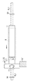
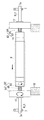
図5は実施例1の従動ロールおよび従動軸受の要部説明図であり、図5Aは媒体搬送ベルトが前側に寄った状態の説明図、図5Bは図5Aの状態から軸位置変移部材が回転した状態の説明図である。
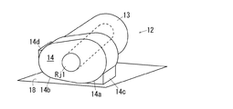
図6は実施例1の片寄り検知部材および軸位置変移部材の要部斜視説明図である。
図5において、回転支持部材の一例としての実施例1の従動ロールRjは、支持部材本体の一例として、前記従動軸Rj1の軸方向中央部に配置され媒体搬送ベルトBを支持するロール本体11を有する。
図5、図6において、前記ロール本体11の前後両側には、片寄り補正部材の一例としてのカムローラ12が従動軸Rj1に対して回転可能に支持されている。前記カムローラ12は、片寄り検知部材の一例としての円筒状の片寄り検知部13と、軸位置変移部材の一例としてのカム部14とを有し、前記片寄り検知部13とカム部14とが一体的に形成されている。
FIG. 5 is an explanatory diagram of the main parts of the driven roll and the driven bearing of the first embodiment, FIG. 5A is an explanatory diagram of a state in which the medium transport belt is close to the front side, and FIG. It is explanatory drawing of the state which carried out.
FIG. 6 is a perspective explanatory view of main parts of the deviation detection member and the shaft position shifting member according to the first embodiment.
In FIG. 5, the driven roll Rj of Example 1 as an example of the rotation support member includes a roll
5 and 6,
図2〜図4、図6において、前記カム部14は、いわゆる偏心カムにより構成されており、半円弧状の外周面を有する円弧状部14aと、円弧状部14aの下方に連続して形成され且つ楕円弧状の外周面を有し外形が連続的に変化する径変化部14bと、を有する。前記カム部14の上端左側には、カム部14の初期の回転位置に移動させるために、カム部14の外周面から接線方向に延びる平面状に形成された初期位置用突き当て部14cが形成されている。また、前記カム部14の下端右側には、カム部14の回転位置の径が最大の位置よりも回転することを規制するために、径が最大の位置から外周面の折線方向に延びる平面状に形成された回転規制部14dが形成されている。
図5において、前記カムローラ12の外端部は、位置固定部材の一例としてのEリング17により軸方向に移動不能な状態で支持されている。
図4、図5において、前記ベルトモジュールBMには、前記カム部14bに対向する位置に、前記カム部14bが突き当てられる基準面の一例としての突き当て面18が形成されている。
2 to 4 and 6, the
In FIG. 5, the outer end portion of the
4 and 5, the belt module BM is formed with an abutting
(実施例1の作用)
前記構成を備えた無端状部材駆動装置の一例である実施例1のベルトモジュールBMでは、媒体搬送ベルトBが駆動されていない状態では、図4Aに示すように、従動軸受7の長孔状の軸受部7aの内面に、従動軸Rj1の外表面が接触した状態で、左右方向に移動自由な状態で支持されている。したがって、従動ローラRjが、軸受部7aにより、従動軸受7に左右方向に移動自由な状態で回転可能に支持されている。このとき、前記従動ローラRjは、長孔状の軸受部7a内にて任意の位置にある。なお、図示しない引張バネによってカムの受け面18方向に引っ張られた状態となるように構成することも可能である。
(Operation of Example 1)
In the belt module BM according to the first embodiment, which is an example of the endless member driving device having the above-described configuration, when the medium transport belt B is not driven, as shown in FIG. The
前記従動ローラRjが、ベルトBが無回転時に自由位置にある場合、前記媒体搬送ベルトBが回転駆動すると、媒体搬送ベルトBの回転に伴って発生するモーメントにより、従動ロールRjが左方に移動する力を受ける。このとき、図4Aに示す状態から、図4Bに示すように、従動軸受7に左右方向に移動自由な状態で支持された従動ロールRjは左方に移動する。そして、前記従動ロールRjは、軸受部7aの左端面の位置決め面に突き当てられた状態で停止し、位置決めされる。したがって、前記媒体搬送ベルトBの回転中は、従動ロールRjは、位置決め面に位置決めされた状態で媒体搬送ベルトBを支持し、媒体搬送ベルトBの回転に伴って従動回転する。
When the driven roller Rj is in a free position when the belt B does not rotate, when the medium conveying belt B is driven to rotate, the driven roll Rj moves to the left due to the moment generated as the medium conveying belt B rotates. Receive the power to do. At this time, from the state shown in FIG. 4A, as shown in FIG. 4B, the driven roll Rj supported by the driven
このとき、実施例1では、カムローラ12のカム部14は外表面が突き当て面18に突き当てられ、従動ロールRjが左側に押しつけられる力により、回転自由なカムローラ12が力を受ける。これにより、カム部14の径変化部14bが突き当て面18に接触した場合には、径が小さい側の外周面が接触する方向に回転し、初期位置用突き当て部14cが突き当て面18に接触した状態で回転が規制され、図4Bに示す初期位置に保持される。すなわち、実施例1では、従動ロールRjの位置決めやカムローラ12の初期位置への位置決めは、媒体搬送ベルトBの回転力を利用しており、所定の位置に移動させるためのバネやモータ等が削減された簡素な構成となり、小型化や省費用化、装置の低騒音化、長寿命化が図られている。
At this time, in Example 1, the
図5において、前記媒体搬送ベルトBが回転中に、駆動ロールRdと従動ロールRjとの間の平行度等により幅方向に片寄ったり、蛇行したりすることがある。図5Aにおいて、媒体搬送ベルトBが前方に片寄ると、媒体搬送ベルトBの前端部が、前側のカムローラ12の片寄り検知部13の外表面に接触する。回転する前記媒体搬送ベルトBが片寄り検知部13の外表面に接触すると、片寄り検知部13が従動回転する力を受け、カムローラ12が回転しようとする。このとき、カムローラ12は、媒体搬送ベルトBの回転に伴うモーメントで受動軸受Rjが左側に押しつけられ、カム部14が突き当て面18に押しつけられる力を受けており、これがカムローラ12を回転させる際の抵抗力として作用している。前記媒体搬送ベルトBの片寄りが小さく、前記突き当て面18に押しつけられることにより抵抗が、媒体搬送ベルトBの片寄り検知部13を従動回転させようとする力、トルクよりも大きい場合は、カムローラ12は回転せず、片寄り検知部13と媒体搬送ベルトBとの間が滑る状態で媒体搬送ベルトBが回転する。
In FIG. 5, while the medium conveying belt B is rotating, the medium conveying belt B may be shifted in the width direction or meandering depending on the parallelism between the driving roll Rd and the driven roll Rj. In FIG. 5A, when the medium conveying belt B is shifted forward, the front end portion of the medium conveying belt B comes into contact with the outer surface of the
図5において、前記媒体搬送ベルトBがさらに片寄って、媒体搬送ベルトBの片寄り検知部13を従動回転させようとする力、トルクが、前記突き当て面18に押しつけられることにより抵抗がよりも大きくなると、カムローラ12が媒体搬送ベルトBの回転に従動回転する。前記カムローラ12が従動回転すると、カム部14が回転し、図5Aに示す状態から図5Bに示すように、径変化部14bが突き当て面18に接触し、従動軸Rj1からの径が大きな外周面が突き当て面18に接触して、従動軸Rj1が傾斜する。前記従動軸Rj1の傾斜により、媒体搬送ベルトBは片寄りが戻される方向の力を受け、片寄りが補正される。このとき、実施例1のカム部14では、従動軸Rj1からの径が最大で、従動軸Rj1の傾斜が最大となる位置よりを越えてカム部14が回転しようとすると、回転規制部14dが突き当て面18に接触してそれ以上の回転が規制される。
In FIG. 5, the medium conveyance belt B is further offset, and the force and torque for causing the
そして、前記媒体搬送ベルトBと片寄り検知部13との接触面が小さくなったり、接触しなくなると、カムローラ12が突き当て面18に突き当てられる力が大きくなり、初期位置の方向に逆回転して、初期位置または力が平衡状態となる位置まで戻る。すなわち、実施例1では、媒体搬送ベルトBの片寄り、蛇行の補正が、従動軸Rj1の軸端に配置され且つ片寄り検知部13と軸位置変移部材の一例であるカム部14とが一体形成されて部品点数が少なく組み立てやすいカムローラ12により行われ、モータやバネ等を使用せずに、片寄り等の補正が行われている。
When the contact surface between the medium transport belt B and the
図7は実施例2の片寄り補正部材の説明図である。
次に本発明の実施例2の説明をするが、この実施例2の説明において、前記実施例1の構成要素に対応する構成要素には同一の符号を付して、その詳細な説明を省略する。
この実施例は、下記の点で前記実施例1と相違しているが、他の点では前記実施例1と同様に構成される。
図7において、実施例2の画像形成装置では、実施例1のカムローラ12に替えて、カムローラ22が使用されている。実施例2のカムローラ22は、片寄り検知部材の一例としての円筒状の片寄り検知部23と、軸位置変移部材の一例として、片寄り検知部23の外表面から外方に突出して形成された軸方向から見た状態で略三角形状のアーム部24とを有する。また、実施例2では、片寄り検知部23とアーム部24は一体的に形成されている。したがって、実施例2では、アーム部24の先端24aが従動軸Rj1からの径が最大の位置となっている。
FIG. 7 is an explanatory diagram of a deviation correction member according to the second embodiment.
Next, a second embodiment of the present invention will be described. In the description of the second embodiment, components corresponding to those of the first embodiment are denoted by the same reference numerals, and detailed description thereof is omitted. To do.
This embodiment is different from the first embodiment in the following points, but is configured in the same manner as the first embodiment in other points.
In FIG. 7, in the image forming apparatus according to the second embodiment, a
(実施例2の作用)
前記構成を備えた実施例2の画像形成装置では、前記略三角形状のアーム部24が突き当て面18に突き当てられることで、従動軸Rj1と突き当て面18との距離が変化し、媒体搬送ベルトBの片寄りを補正する方向に従動軸Rj1を傾斜される。したがって、実施例2の画像形成装置Uも、実施例1と同様に、媒体搬送ベルトBの回転力を利用して、従動軸Rj1の位置決めがされると共に、カムローラ22の媒体搬送ベルトBに対する従動回転に応じて従動軸Rj1が傾斜して、媒体搬送ベルトBの片寄り、蛇行が補正される。
(Operation of Example 2)
In the image forming apparatus according to the second embodiment having the above-described configuration, the distance between the driven shaft Rj1 and the abutting
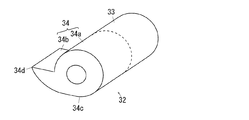
図8は実施例3の片寄り補正部材の説明図である。
次に本発明の実施例3の説明をするが、この実施例3の説明において、前記実施例1の構成要素に対応する構成要素には同一の符号を付して、その詳細な説明を省略する。
この実施例は、下記の点で前記実施例1と相違しているが、他の点では前記実施例1と同様に構成される。
図8において、実施例3の画像形成装置では、実施例1のカムローラ12に替えて、カムローラ32が使用されている。実施例3のカムローラ32は、片寄り検知部材の一例としての円筒状の片寄り検知部33と、軸位置変移部材の一例として、片寄り検知部33の外端部に形成されたカム部34とを有する。実施例3の前記カム部34は、前記片寄り検知部33と同様の円筒部34aと、円筒部から径方向に突出する爪状の径変化部34bとを有する。前記径変化部34bは、前記円筒部34aの外表面に連続して形成され、連続的に径が大きくなり、円筒部34aと径変化部34bとの境界部34cからカムローラ32が90°回転時に、従動軸Rj1からの径が最大になる径最大部34dに移動するように設定されている。
FIG. 8 is an explanatory diagram of a deviation correction member according to the third embodiment.
Next, the third embodiment of the present invention will be described. In the description of the third embodiment, the same reference numerals are given to the components corresponding to the components of the first embodiment, and the detailed description thereof will be omitted. To do.
This embodiment is different from the first embodiment in the following points, but is configured in the same manner as the first embodiment in other points.
In FIG. 8, in the image forming apparatus of the third embodiment, a
(実施例3の作用)
前記構成を備えた実施例3の画像形成装置では、カムローラ32が回転して、径変化部34bが突き当て面18に接触することで、従動軸Rj1と突き当て面18との距離が変化し、媒体搬送ベルトBの片寄りが補正される。このとき、実施例3では、90°の回転で最大まで変化し、従動軸Rj1を短時間で急激に傾斜させることが可能となっており、短時間で媒体搬送ベルトBの片寄りが補正される。
したがって、実施例3の画像形成装置Uも、実施例1と同様に、媒体搬送ベルトBの回転力を利用して、従動軸Rj1の位置決めがされると共に、カムローラ22の媒体搬送ベルトBに対する従動回転に応じて従動軸Rj1が傾斜して、媒体搬送ベルトBの片寄り、蛇行が補正される。
(Operation of Example 3)
In the image forming apparatus according to the third embodiment having the above-described configuration, the
Accordingly, in the image forming apparatus U of the third embodiment, the driven shaft Rj1 is positioned using the rotational force of the medium transport belt B and the
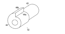
図9は実施例4の片寄り補正部材の説明図である。
次に本発明の実施例4の説明をするが、この実施例4の説明において、前記実施例1の構成要素に対応する構成要素には同一の符号を付して、その詳細な説明を省略する。
この実施例は、下記の点で前記実施例1と相違しているが、他の点では前記実施例1と同様に構成される。
図9において、実施例4の画像形成装置では、実施例1のカムローラ12に替えて、カムローラ42が使用されている。実施例4のカムローラ42は、片寄り検知部材の一例としての円筒状の片寄り検知部43と、軸位置変移部材の一例として、片寄り検知部43の外端部に形成されたカム部44とを有する。実施例4の前記カム部44は、外周面が軸方向から見た状態で、従動軸Rj1を中心とする螺旋状に形成されており、外径が連続的に大きくなるように形成されている。前記カム部44では、外径が最小の径最小部44aが片寄り検知部43と同様に形成され、径最小部44aから360°回転した位置に径最大部44bが対応するようになっている。
FIG. 9 is an explanatory diagram of a deviation correction member according to the fourth embodiment.
Next, a description will be given of a fourth embodiment of the present invention. In the description of the fourth embodiment, components corresponding to the components of the first embodiment are denoted by the same reference numerals, and detailed description thereof is omitted. To do.
This embodiment is different from the first embodiment in the following points, but is configured in the same manner as the first embodiment in other points.
In FIG. 9, in the image forming apparatus of the fourth embodiment, a
(実施例4の作用)
前記構成を備えた実施例4の画像形成装置では、カムローラ42が回転して、カム部44が突き当て面18に接触することで、従動軸Rj1と突き当て面18との距離が変化し、媒体搬送ベルトBの片寄りが補正される。このとき、実施例4では、実施例3の場合に比べて径の変化が急激ではなく、従動軸Rj1の傾斜が細かく、精度良く調整可能となっている。
したがって、実施例4の画像形成装置Uも、実施例1と同様に、媒体搬送ベルトBの回転力を利用して、従動軸Rj1の位置決めがされると共に、カムローラ22の媒体搬送ベルトBに対する従動回転に応じて従動軸Rj1が傾斜して、媒体搬送ベルトBの片寄り、蛇行が補正される。
(Operation of Example 4)
In the image forming apparatus according to the fourth embodiment having the above-described configuration, the
Accordingly, in the image forming apparatus U according to the fourth embodiment, the driven shaft Rj1 is positioned using the rotational force of the medium transport belt B and the
図10は実施例5のベルトモジュールの説明図であり、実施例1の図3に対応する図である。
図11は実施例5のプリンタの要部説明図であり、実施例1の図4Bに対応する図である。
次に本発明の実施例5の説明をするが、この実施例5の説明において、前記実施例1の構成要素に対応する構成要素には同一の符号を付して、その詳細な説明を省略する。
この実施例は、下記の点で前記実施例1と相違しているが、他の点では前記実施例1と同様に構成される。
図10、図11において、実施例5のベルトモジュールBMでは、枠体1′の前側枠体2′および後側枠体3′は、上側の前側枠体本体52および後側枠体本体53と、前記枠体本体52,53の下端部に回転軸52a,53aを中心として回転可能に支持された前側回転枠体54および後側回転枠体55と、実施例1と同様の連結枠体4とを有する。
FIG. 10 is an explanatory diagram of the belt module according to the fifth embodiment and corresponds to FIG. 3 according to the first embodiment.
FIG. 11 is an explanatory diagram of a main part of the printer according to the fifth embodiment, and corresponds to FIG. 4B according to the first embodiment.
Next, the fifth embodiment of the present invention will be described. In the description of the fifth embodiment, the same reference numerals are given to the components corresponding to the components of the first embodiment, and the detailed description thereof will be omitted. To do.
This embodiment is different from the first embodiment in the following points, but is configured in the same manner as the first embodiment in other points.
10 and 11, in the belt module BM of the fifth embodiment, the front frame body 2 'and the rear frame body 3' of the frame body 1 'are connected to the upper front
図10において、各枠体本体52,53に、付勢部材一端支持部の一例として、ばね一端取り付け部52bが形成されており、前記各回転枠体54,55には、付勢部材他端支持部の一例として、ばね他端取り付け部54aが形成されている。なお、図10では後側のばね一端取り付け部およびばね他端取り付け部の図示は省略する。そして、前記回転軸52a、53aには、位置決め付勢部材の一例としてのねじりばね57が装着されており、ねじりばね57の一端がばね一端取り付け部52bに支持され、他端がばね他端取り付け部54aに支持されている。図11において、したがって、実施例5では、前記ねじりばね57により、回転枠体54,55は、ベルトモジュールBMの右側に配置された基準面18′側に付勢されている。
In FIG. 10, each
図10、図11において、前記回転枠体54,55には、実施例1の軸受取付口2a,3aと同様の軸受取り付け口54b,55bが形成されており、軸受部材の一例としての従動軸受58,59が上下方向に移動可能に支持されている。実施例5の従動軸受58,59は、従動軸Rj1を回転可能に支持している。なお、実施例5では、前記従動ローラRjは実施例1と同様に構成されており、カムローラ12は突き当て面18′が左右逆になったことに対応して、実施例1の場合に対して180°回転した状態で支持されている。
10 and 11, the
(実施例5の作用)
前記構成を備えた実施例5の画像形成装置Uでは、ベルトモジュールBMは、回転枠体54,55を有し、実施例1の場合と異なり、従動軸Rj1の位置決めは媒体搬送ベルトBの回転力を利用するのではなく、ねじりばね57の付勢力を利用している。そして、実施例1と同様に、媒体搬送ベルトBが片寄ってカムローラ12の片寄り検知部13に接触して乗り上げると、ねじりばね57の付勢力と、カムローラ12を従動回転させるトルクとの関係で、カムローラ12が回転し、従動軸Rj1が傾斜して、片寄りが補正される。すなわち、実施例5では、カムローラ12を回転させるモータ等が不要であると共に、片寄りの検知と軸の変移が1つの部材であるカムローラ12で行われ、構成の簡素化、部品点数の削減が図られている。
(Operation of Example 5)
In the image forming apparatus U according to the fifth embodiment having the above-described configuration, the belt module BM includes
図12は実施例6のベルトモジュールの説明図であり、実施例5の図10に対応する図である。
図13は実施例6のプリンタの要部説明図であり、実施例5の図11に対応する図である。
図14は実施例6の従動ロールおよび従動軸受の要部説明図であって、実施例1の図5に対応する図である。
次に本発明の実施例6の説明をするが、この実施例6の説明において、前記実施例1,5の構成要素に対応する構成要素には同一の符号を付して、その詳細な説明を省略する。
この実施例は、下記の点で前記実施例1,5と相違しているが、他の点では前記実施例1,5と同様に構成される。
図12、図13において、実施例6のベルトモジュールBMでは、枠体1″は、実施例5と同様の前側枠体2′および前側回転枠体54と、実施例1と同様の後側枠体2とを有する。また、図12〜図14において、実施例6では、実施例5と同様の従動軸受58,59が使用されており、カムローラ12は、従動ローラRjの前側のみに配置されている。
FIG. 12 is an explanatory diagram of the belt module according to the sixth embodiment and corresponds to FIG. 10 according to the fifth embodiment.
FIG. 13 is an explanatory diagram of a main part of the printer of the sixth embodiment and corresponds to FIG. 11 of the fifth embodiment.
FIG. 14 is an explanatory diagram of a main part of the driven roll and the driven bearing of the sixth embodiment and corresponds to FIG. 5 of the first embodiment.
Next, the sixth embodiment of the present invention will be described. In the description of the sixth embodiment, the same reference numerals are given to the components corresponding to the components of the first and fifth embodiments, and the detailed description thereof will be given. Is omitted.
This embodiment is different from the first and fifth embodiments in the following points, but is configured similarly to the first and fifth embodiments in other points.
12 and 13, in the belt module BM of the sixth embodiment, the
図13において、実施例6のベルトモジュールBMでは、後側枠体2に対して、前側回転枠体54が右方に傾斜して突き当て面18′側に配置された状態となっており、初期状態では、媒体搬送ベルトBが前側に片寄るように設定されている。
In FIG. 13, in the belt module BM of Example 6, the front
(実施例6の作用)
前記構成を備えた実施例6の画像形成装置Uでは、図14Aに示すように媒体搬送ベルトBが前側に片寄ってカムローラ12の片寄り検知部13に接触して乗り上げると、ねじりばね57の付勢力と、カムローラ12を従動回転させるトルクとの関係で、図14Bに示すようにカムローラ12が回転し、従動軸Rj1が傾斜して、片寄りが補正される。すなわち、実施例6では媒体搬送ベルトBが前側に片寄るように設定されており、後側の媒体搬送ベルトBの片寄りを補正するための構成が削除されている。よって、実施例6では、実施例5の場合に比べて、さらに構成の簡素化、部品点数の削減が図られている。
(Operation of Example 6)
In the image forming apparatus U according to the sixth embodiment having the above-described configuration, when the medium conveyance belt B is offset toward the front side and contacts the
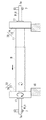
図15は実施例7の従動ロールおよび従動軸受の要部説明図であって、実施例1の図5Aに対応する図である。
次に本発明の実施例7の説明をするが、この実施例7の説明において、前記実施例1の構成要素に対応する構成要素には同一の符号を付して、その詳細な説明を省略する。
この実施例は、下記の点で前記実施例1と相違しているが、他の点では前記実施例1と同様に構成される。
図15において、実施例7のベルトモジュールBMでは、実施例1のカムローラ12に替えて、カムローラ72が使用されている。実施例7のカムローラ72は、実施例1のカムローラ12の片寄り検知部13が省略され、軸位置変移部材の一例としてのカム部74の内側端面により片寄り検知部材の一例としての片寄り検知面73が構成されている。すなわち、実施例7でも、片寄り検知部材と軸位置変移部材とが一体的に形成されている。
FIG. 15 is an explanatory diagram of a main part of the driven roll and the driven bearing of the seventh embodiment and corresponds to FIG. 5A of the first embodiment.
Next, the seventh embodiment of the present invention will be described. In the description of the seventh embodiment, the same reference numerals are given to the components corresponding to the components of the first embodiment, and the detailed description thereof will be omitted. To do.
This embodiment is different from the first embodiment in the following points, but is configured in the same manner as the first embodiment in other points.
In FIG. 15, in the belt module BM of the seventh embodiment, a cam roller 72 is used instead of the
(実施例7の作用)
前記構成を備えた実施例7の画像形成装置Uでは、図15に示すように媒体搬送ベルトBが前側に片寄ると、媒体搬送ベルトBの前端縁がカムローラ72の片寄り検知面73に接触する。これにより、カムローラ72が回転する力を受け、力が弱い状態では回転せず、ベルトがさらに片寄って、媒体搬送ベルトBの前端縁と片寄り検知面73との面圧が高まって回転させるトルクが上昇すると、カム部74が回転する。前記カム部74が回転すると、従動軸Rj1と突き当て面18との距離が変化し、従動軸Rj1が傾斜して、片寄りが補正される。よって、実施例7では、実施例1の場合比べて、さらに構成の簡素化、部品点数の削減が図られている。
(Operation of Example 7)
In the image forming apparatus U according to the seventh embodiment having the above-described configuration, as illustrated in FIG. 15, when the medium transport belt B is shifted to the front side, the front edge of the medium transport belt B contacts the
図16は実施例8の従動ロールおよび従動軸受の要部説明図であって、実施例1の図5Aに対応する図である。
次に本発明の実施例8の説明をするが、この実施例8の説明において、前記実施例1の構成要素に対応する構成要素には同一の符号を付して、その詳細な説明を省略する。
この実施例は、下記の点で前記実施例1と相違しているが、他の点では前記実施例1と同様に構成される。
図16において、実施例8のベルトモジュールBMでは、実施例1のカムローラ12に替えて、片寄り補正部材82が使用されている。実施例8の片寄り補正部材82は、円筒ローラ状の片寄り検知部83と、軸位置変移部材の一例としての実施例1のカム部14と同様に構成された偏心カム状のカム84とを有し、片寄り検知部材83とカム84との間に、回転伝達規制部材の一例としてのバネクラッチ85が装着されている。
FIG. 16 is an explanatory diagram of a main part of the driven roll and the driven bearing of the eighth embodiment, corresponding to FIG. 5A of the first embodiment.
Next, an eighth embodiment of the present invention will be described. In the description of the eighth embodiment, components corresponding to the components of the first embodiment are denoted by the same reference numerals, and detailed description thereof is omitted. To do.
This embodiment is different from the first embodiment in the following points, but is configured in the same manner as the first embodiment in other points.
In FIG. 16, in the belt module BM of the eighth embodiment, a
(実施例8の作用)
前記構成を備えた実施例8の画像形成装置Uでは、媒体搬送ベルトBが前側に片寄って、片寄り検知部材83に接触すると、片寄り検知部材83は、媒体搬送ベルトBと共に従動回転し始め、バネクラッチに圧がかかるとバネクラッチが軸に対し巻きつき始めカム84に回転トルクが生じる。その際、搬送ベルトBの蛇行力が大きければ大きい程カム84は回転角度を大きくする。軸の蛇行量が大きく、軸の補正量を多く必要とする場合、実施例1と同様の回転規制部14dの回転規制によりカム84は軸変位範囲最高点で回転を止める。それにより片寄り検知部材83とカム84との間に設置され、カム84を回転方向に廻すバネクラッチ85の伝達許容トルクを超えると、片寄り検知部材のみが無端状部材と共に回転する。よって、実施例1のように、カム部14が回転しない状態で媒体搬送ベルトBの内表面と片寄り検知部13の外表面とが擦れる場合に比べて、媒体搬送ベルトBおよび片寄り検知部材83の摩耗や、擦れる際の音が低減される。したがって、実施例8では、摩耗に伴う経時的な片寄り補正能力の低下の防止や、長寿命化が図られている。
(Operation of Example 8)
In the image forming apparatus U according to the eighth embodiment having the above-described configuration, when the medium conveyance belt B is shifted to the front side and comes into contact with the
図17は実施例9の従動ロールおよび従動軸受の前側端部の要部説明図である。
次に本発明の実施例9の説明をするが、この実施例9の説明において、前記実施例1,7,8の構成要素に対応する構成要素には同一の符号を付して、その詳細な説明を省略する。
この実施例は、下記の点で前記実施例1,7,8と相違しているが、他の点では前記実施例1,7,8と同様に構成される。
図17において、実施例9のベルトモジュールBMでは、片寄り補正部材92は、従動ローラRjよりも大径の円筒状の片寄り検知部材93と、実施例1のカム部14と同様に構成された軸位置変移部材の一例としてのカム94とを有し、前記片寄り検知部材93の軸部分とカム94の軸部分との間には、回転伝達規制部材の一例としてのトルクリミッタ95が装着されている。
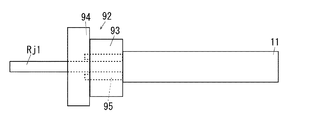
FIG. 17 is an explanatory diagram of a main part of the front end portion of the driven roll and the driven bearing according to the ninth embodiment.
Next, the ninth embodiment of the present invention will be described. In the description of the ninth embodiment, the same reference numerals are given to the components corresponding to the components of the first, seventh, and eighth embodiments, and the details thereof will be described. The detailed explanation is omitted.
This embodiment differs from the first, seventh, and eighth embodiments in the following points, but is configured in the same manner as the first, seventh, and eighth embodiments in other points.
In FIG. 17, in the belt module BM of the ninth embodiment, the
(実施例9の作用)
前記構成を備えた実施例9の画像形成装置Uでは、媒体搬送ベルトBが片寄って、片寄り検知部材93の端部側面に接触すると、片寄り検知部材93とカム部94は、媒体搬送ベルトBと共に従動回転する。その後、蛇行量が大きく、補正量を多く必要とする場合、実施例1と同様の回転規制部14dの回転規制によりカムは軸変位範囲最高点で回転を止める。そこで、片寄り検知部材93とカム94との間に取り付けられ、お互いの伝達トルクを規制するトルクリミッタ95の伝達許容トルクを超えると、片寄り検知部材93のみが搬送ベルトBと共に回転する。
したがって、実施例9では、実施例8と同様に片寄り検知部材93はカム部94が回転しなくても媒体搬送ベルトBと共に回転し、媒体搬送ベルトBおよび片寄り検知部材93の摩耗や、擦れる際の音が低減される。したがって、実施例9では、摩耗に伴う経時的な片寄り補正能力の低下の防止や、長寿命化が図られている。
(Operation of Example 9)
In the image forming apparatus U according to the ninth embodiment having the above-described configuration, when the medium conveyance belt B is offset and contacts the side surface of the end portion of the
Therefore, in the ninth embodiment, as in the eighth embodiment, the
図18は実施例10の従動ロールおよび従動軸受の前側端部の要部説明図である。
次に本発明の実施例10の説明をするが、この実施例10の説明において、前記実施例1,7〜9の構成要素に対応する構成要素には同一の符号を付して、その詳細な説明を省略する。
この実施例は、下記の点で前記実施例1と相違しているが、他の点では前記実施例1,7〜9と同様に構成される。
図18において、実施例10のベルトモジュールBMでは、片寄り補正部材102は、従動ローラRjと同径の円筒状の片寄り検知部材103と、実施例9と同様の軸位置変移部材の一例としてのカム94とトルクリミッタ95とを有する。
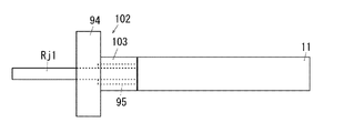
FIG. 18 is an explanatory view of main parts of the front end portion of the driven roll and the driven bearing of the tenth embodiment.
Next, a description will be given of a tenth embodiment of the present invention. In the description of the tenth embodiment, the same reference numerals are given to the components corresponding to the components of the first and seventh embodiments, and the details thereof will be described. The detailed explanation is omitted.
This embodiment is different from the first embodiment in the following points, but is configured in the same manner as the first and seventh embodiments in other points.
In FIG. 18, in the belt module BM of the tenth embodiment, the
(実施例10の作用)
前記構成を備えた実施例10の画像形成装置Uでは、媒体搬送ベルトBが片寄って、片寄り検知部材103の外周部に乗り上げると、片寄り検知部材103とカム部84は、媒体搬送ベルトBと共に従動回転する。その後の動作と働きは、前記実施例9と同様である。
したがって、実施例10では、実施例8、9と同様に片寄り検知部材103はカム部94が回転しなくても媒体搬送ベルトBと共に回転し、媒体搬送ベルトBおよび片寄り検知部材93の摩耗や、擦れる際の音が低減される。したがって、実施例10では、摩耗に伴う経時的な片寄り補正能力の低下の防止や、長寿命化が図られている。
(Operation of Example 10)
In the image forming apparatus U according to the tenth embodiment having the above-described configuration, when the medium conveyance belt B is offset and rides on the outer periphery of the
Therefore, in the tenth embodiment, as in the eighth and ninth embodiments, the
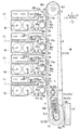
図19は実施例11の画像形成装置の全体説明図である。
次に本発明の実施例11の説明をするが、この実施例11の説明において、前記実施例1の構成要素に対応する構成要素には同一の符号を付して、その詳細な説明を省略する。
この実施例は、下記の点で前記実施例1と相違しているが、他の点では前記実施例1と同様に構成される。
図19において、実施例11の画像形成装置の一例としてのデジタルカラー複写機Uは、画像記録装置の一例としてのプリンタ部U1′、画像読取り装置の一例としてのイメージスキャナU2′、自動原稿搬送装置U3′を有している。
FIG. 19 is a diagram illustrating the entire image forming apparatus according to the eleventh embodiment.
Next, an eleventh embodiment of the present invention will be described. In the description of the eleventh embodiment, components corresponding to those of the first embodiment are denoted by the same reference numerals, and detailed description thereof is omitted. To do.
This embodiment is different from the first embodiment in the following points, but is configured in the same manner as the first embodiment in other points.
In FIG. 19, a digital color copying machine U as an example of an image forming apparatus according to an eleventh embodiment includes a printer unit U1 ′ as an example of an image recording apparatus, an image scanner U2 ′ as an example of an image reading apparatus, and an automatic document feeder. U3 '.
前記自動原稿搬送装置U3′は、イメージスキャナU2′上面の透明な原稿台の一例としての婦ラテンガラスPG上に支持されている。
前記自動原稿搬送装置U3′は、複写しようとする複数の原稿Giが重ねて載置される原稿給紙部の一例としての原稿給紙トレイTG1を有している。前記原稿給紙トレイTG1に載置された複数の各原稿Giは順次プラテンガラスPG上の複写位置を通過して、原稿排出部材の一例としての原稿排出ロールGR2から、原稿排出部の一例としての原稿排紙トレイTG2に排出されるように構成されている。
The automatic document feeder U3 ′ is supported on a latin latin glass PG as an example of a transparent document table on the upper surface of the image scanner U2 ′.
The automatic document feeder U3 'has a document feed tray TG1 as an example of a document feed unit on which a plurality of documents Gi to be copied are placed in an overlapping manner. Each of the plurality of documents Gi placed on the document feed tray TG1 sequentially passes through a copy position on the platen glass PG, and from a document discharge roll GR2 as an example of a document discharge member, as an example of a document discharge unit. It is configured to be discharged to the document discharge tray TG2.
前記自動原稿搬送装置U3′は、その後端部に設けた左右方向に延びる回転軸により前記プラテンガラスPG上面に対して回動可能であり、手動原稿読取り時に原稿Giを作業者が手でプラテンガラスPG上に置く場合に上方に回動される。
前記イメージスキャナU2′は、利用者が複写開始等の作動指令信号を入力操作する操作部UIを有している。
前記透明なプラテンガラスPGの下方には原稿画像を読み取るための露光光学系Aが配置されている。
The automatic document feeder U3 ′ can be rotated with respect to the upper surface of the platen glass PG by a rotation shaft provided in the rear end portion extending in the left-right direction. When placed on the PG, it is rotated upward.
The image scanner U2 'has an operation unit UI for a user to input an operation command signal for starting copying.
An exposure optical system A for reading a document image is disposed below the transparent platen glass PG.
前記自動原稿搬送装置U3′でプラテンガラスPG上面に搬送されて前記複写位置を通過する原稿または手動でプラテンガラスPG上に置かれた原稿からの反射光は、前記露光光学系Aを介して、固体撮像素子CCDで電気信号に変換される。
画像処理部IPSは、固体撮像素子CCDから入力される電気信号を画像情報に変換して一時的に記憶し、前記画像情報を所定の時期に潜像形成用の画像情報として、潜像形成装置駆動回路の一例としてのレーザ駆動回路DLに出力する。
Reflected light from a document which is transported to the upper surface of the platen glass PG by the automatic document feeder U3 ′ and passes through the copy position or a document which is manually placed on the platen glass PG, passes through the exposure optical system A, It is converted into an electric signal by the solid-state imaging device CCD.
The image processing unit IPS converts an electrical signal input from the solid-state imaging device CCD into image information and temporarily stores the image information, and uses the image information as image information for forming a latent image at a predetermined time. It outputs to the laser drive circuit DL as an example of a drive circuit.
レーザ駆動回路DLは、入力された画像情報に応じて駆動信号を潜像形成装置ROSに出力する。なお、前記操作部UI、画像処理部IPSおよびレーザ駆動回路DLと、後述の現像ロールR0、1次転写ロールT1y,T1m,T1c,T1k、2次転写ロールT2b等にバイアス電圧を印加する電源回路E等の動作は制御部Cにより制御される。
前記画像処理部IPSが出力するYMCKの4色の画像情報が入力されたレーザ駆動回路DLは、入力された前記各色の画像情報に応じた各色の駆動信号を所定の時期に、各色の潜像形成装置ROSy,ROSm,ROSc,ROSk,に出力する。
The laser drive circuit DL outputs a drive signal to the latent image forming apparatus ROS according to the input image information. The operation unit UI, the image processing unit IPS, and the laser driving circuit DL, and a power supply circuit that applies a bias voltage to the developing roll R0, primary transfer rolls T1y, T1m, T1c, T1k, and the secondary transfer roll T2b, which will be described later. Operations such as E are controlled by the control unit C.
The laser driving circuit DL to which the image information of the four colors YMCK output from the image processing unit IPS is input, the driving signal of each color corresponding to the input image information of each color at a predetermined time, the latent image of each color Output to the forming apparatuses ROSy, ROSm, ROSc, ROSk.
像保持体の一例としての感光体Py,Pm,Pc,Pkは、それぞれ、耐電部材の一例としての帯電ロールCRy,CRm,CRc,CRkにより一様に帯電された後、前記各色の潜像形成装置ROSy〜ROSkの出力する潜像書き込み光Lによりその表面に静電潜像が形成される。前記感光体Py,Pm,Pc,Pk表面の静電潜像はそれぞれ、各現像器Gy,Gm,Gc,Gkと対向する現像領域において、可視像の一例としての各色YMCKのトナー像に現像される。前記各色の現像器Gy,Gm,Gc,Gkの現像容器Vには、現像剤収用容器の一例としてのトナーカートリッジTy〜Tkから各色の現像剤が補給される。 The photoreceptors Py, Pm, Pc, and Pk as an example of the image carrier are uniformly charged by the charging rolls CRy, CRm, CRc, and CRk as examples of the electric-resistant members, respectively, and then the latent images of the respective colors are formed. An electrostatic latent image is formed on the surface of the latent image writing light L output from the devices ROSy to ROSk. The electrostatic latent images on the surfaces of the photoreceptors Py, Pm, Pc, and Pk are developed into toner images of each color YMCK as an example of a visible image in a developing area that faces the developing units Gy, Gm, Gc, and Gk, respectively. Is done. Developers of each color are supplied from toner cartridges Ty to Tk as an example of a developer collecting container to the developing containers V of the developing devices Gy, Gm, Gc, and Gk of the respective colors.
前記感光体Py,Pm,Pc,Pk表面に現像された各色YMCKのトナー像は、前記各感光体Py,Pm,Pc,Pkと、無端状部材の一例であり且つ中間転写体の一例としての中間転写ベルトB′とが接触する1次転写領域Q3に搬送される。前記各1次転写領域Q3において中間転写ベルトB′の裏面側に配置された一次転写器の一例としての1次転写ロールT1y,T1m,T1c,T1kには、制御部Cにより制御される電源回路Eから所定の時期に現像剤の帯電極性と逆極性の1次転写電圧が印加される。前記各感光体Py〜Pk上のトナー像は前記各1次転写ロールT1y,T1m,T1c,T1kに対向する1次転写領域Q3において中間転写ベルトB′に順次重ねて1次転写される。 The toner image of each color YMCK developed on the surface of the photoconductors Py, Pm, Pc, and Pk is an example of each of the photoconductors Py, Pm, Pc, and Pk, an endless member, and an example of an intermediate transfer member. The intermediate transfer belt B ′ is conveyed to the primary transfer region Q3 where it contacts. The primary transfer rolls T1y, T1m, T1c, and T1k as an example of the primary transfer unit disposed on the back side of the intermediate transfer belt B 'in each primary transfer region Q3 include a power supply circuit controlled by the control unit C. A primary transfer voltage having a polarity opposite to the charging polarity of the developer is applied at a predetermined time from E. The toner images on the respective photoreceptors Py to Pk are primary-transferred on the intermediate transfer belt B ′ sequentially in the primary transfer region Q3 facing the primary transfer rolls T1y, T1m, T1c, T1k.
1次転写後の感光体Py,Pm,Pc,Pk表面の残留現像剤は、像保持体清掃器の一例としての感光体クリーナCLpで除去される。
前記各感光体Py〜Pk、各色の潜像形成装置ROSy〜ROSk、各色の現像器Gy〜Gkによって、前記各感光体Py〜Pk上に各色のトナー像を形成する可視像形成装置の一例として、各色のトナー像形成装置UY,UM,UC,UKが構成される。
Residual developer on the surface of the photoreceptors Py, Pm, Pc, and Pk after the primary transfer is removed by a photoreceptor cleaner CLp as an example of an image carrier cleaner.
An example of a visible image forming apparatus that forms a toner image of each color on each of the photoreceptors Py to Pk by each of the photoreceptors Py to Pk, each color latent image forming device ROSy to ROSk, and each color developing device Gy to Gk. As described above, toner image forming apparatuses UY, UM, UC, and UK for each color are configured.
前記各色の感光体Py,Pm,Pc,Pkの下方には左右一対の案内部材の一例としてのスライドレールSR,SRにより、被案内枠体の一例としてのスライドフレームF1が前後方向に移動可能に支持されている。前記スライドフレームF1には、実施例2の無端状部材駆動装置の一例であり且つ中間転写体駆動装置の一例としてのベルトモジュールBM′の支持枠体であるベルトフレームF2が支持されている。前記ベルトフレームF2は、中間転写ベルトB′が感光体Py〜Pkに接触する上昇した動作位置と、中間転写ベルトB′が感光体Py〜Pkから下方に離れた保守位置の一例としてのメンテナンス位置との間で昇降可能に支持されている。前記ベルトモジュールBM′がメンテナンス位置に下降した状態では、前記スライドフレームF1およびこれに支持されたベルトモジュールBM′を、前記感光体Py〜Pkと摩擦接触させることなく、プリンタ部U1′に対して出入させることができるように構成されている。
前記スライドフレームF1を前後移動させる構成およびベルトモジュールBM′を昇降させる構成は、例えば、特開平8−171248号公報に記載されていて従来公知であり、従来公知の種々の構成を採用することが可能である。
A slide frame F1 as an example of a guided frame body is movable in the front-rear direction by slide rails SR and SR as an example of a pair of left and right guide members below the photoconductors Py, Pm, Pc, and Pk of each color. It is supported. The slide frame F1 supports a belt frame F2 which is an example of an endless member driving device of Example 2 and which is a support frame of a belt module BM ′ as an example of an intermediate transfer member driving device. The belt frame F2 includes a raised operation position where the intermediate transfer belt B ′ contacts the photoconductors Py to Pk, and a maintenance position as an example of a maintenance position where the intermediate transfer belt B ′ is separated downward from the photoconductors Py to Pk. It is supported so that it can move up and down. When the belt module BM ′ is lowered to the maintenance position, the slide frame F1 and the belt module BM ′ supported by the slide frame F1 are not brought into frictional contact with the photoreceptors Py to Pk with respect to the printer unit U1 ′. It is configured to be able to enter and exit.
The configuration for moving the slide frame F1 back and forth and the configuration for moving the belt module BM ′ up and down are described in, for example, Japanese Patent Laid-Open No. 8-171248, and are conventionally known, and various conventionally known configurations can be adopted. Is possible.
前記ベルトモジュールBM′は、前記中間転写ベルトB′と、駆動支持部材の一例としてのベルト駆動ロールRd、張力付与部材の一例としてのテンションロールRt、蛇行防止部材の一例としてのウォーキングロールRw、従動部材の一例としての複数のアイドラロールRfおよび二次転写対向部材の一例としてのバックアップロールT2aを含むベルト支持ロールRd,Rt,Rw,Rf,T2aと、前記4個の1次転写ロールTy,Tm,Tc,Tkとを有している。そして、前記中間転写ベルトB′は前記ベルト支持ロールRd,Rt,Rw,Rf,T2aにより矢印Ya方向に回転移動可能に支持されている。すなわち、実施例11では、ベルトモジュールBM′は、無端状部材を支持する回転支持部材の一例として、ベルト駆動ロールRd、テンションロールRt、ウォーキングロールRw、複数のアイドラロールRfおよびバックアップロールT2aを有する。 The belt module BM ′ includes the intermediate transfer belt B ′, a belt driving roll Rd as an example of a driving support member, a tension roll Rt as an example of a tension applying member, a walking roll Rw as an example of a meandering prevention member, and a follower. Belt support rolls Rd, Rt, Rw, Rf, T2a including a plurality of idler rolls Rf as an example of members and a backup roll T2a as an example of a secondary transfer counter member, and the four primary transfer rolls Ty, Tm , Tc, Tk. The intermediate transfer belt B ′ is supported by the belt support rolls Rd, Rt, Rw, Rf, T2a so as to be rotatable in the direction of the arrow Ya. That is, in Example 11, the belt module BM ′ includes a belt driving roll Rd, a tension roll Rt, a walking roll Rw, a plurality of idler rolls Rf, and a backup roll T2a as an example of a rotation support member that supports an endless member. .
前記バックアップロールT2aに接する中間転写ベルトB′の表面に対向して、二次転写部材の一例としての2次転写ロールT2bが配置されており、中間転写ベルトB′および2次転写ロールT2bの対向する領域には2次転写領域Q4が形成される。前記2次転写ロールT2bには制御部Cにより制御される電源回路Eから所定の時期に現像剤の帯電極性と逆極性の2次転写電圧が印加される。前記2次転写ロールT2bに対向して配置された前記バックアップロールT2aは接地されており、前記2次転写ロールT2bに2次転写電圧が印加されたときには、前記2次転写ロールT2bおよびバックアップロールT2a間には2次転写電界が形成される。前記バックアップロールT2aおよび2次転写ロールT2bにより2次転写器T2が構成される。
前記4個の1次転写ロールT1y,T1m,T1c,T1kおよび中間転写ベルトB′を含むベルトモジュールBM′と、2次転写器T2等により、トナー像形成装置UY,UM,UC,UKの感光体Py〜Pk表面に形成されたトナー像を記録媒体Sに転写する転写装置BM′+T2が構成されている。
A secondary transfer roll T2b as an example of a secondary transfer member is disposed opposite to the surface of the intermediate transfer belt B 'in contact with the backup roll T2a, and the intermediate transfer belt B' and the secondary transfer roll T2b are opposed to each other. A secondary transfer region Q4 is formed in the region to be processed. A secondary transfer voltage having a polarity opposite to the charging polarity of the developer is applied to the secondary transfer roll T2b from a power supply circuit E controlled by the control unit C at a predetermined time. The backup roll T2a disposed facing the secondary transfer roll T2b is grounded, and when a secondary transfer voltage is applied to the secondary transfer roll T2b, the secondary transfer roll T2b and the backup roll T2a. A secondary transfer electric field is formed between them. The backup roll T2a and the secondary transfer roll T2b constitute a secondary transfer device T2.
The belt module BM ′ including the four primary transfer rolls T1y, T1m, T1c, T1k and the intermediate transfer belt B ′, the secondary transfer unit T2, and the like, expose the toner image forming apparatuses UY, UM, UC, UK. A transfer device BM ′ + T2 for transferring the toner image formed on the surface of the bodies Py to Pk to the recording medium S is configured.
前記プリンタ部U1′の下部には、記録媒体Sを収容した給紙容器TR1〜TR3および給紙用媒体搬送路SH1が設けられている。また、前記給紙用媒体搬送路SH1には手差給紙部TR4から給紙できるように構成されている。前記給紙容器TR1〜TR3に収容された記録媒体Sは、所定の時期に取出部材の一例としてのピックアップロールRpにより取り出され、捌き部材の一例としてのさばきロールRsで1枚づつ分離されて、搬送部材の一例としての複数の搬送ロールRaにより、給紙時期調整部材の一例としてのレジロールRrに搬送される。また、手差給紙部TR4から給紙された記録媒体Sは搬送ロールRaによりレジロールRrに搬送される。前記レジロールRrに搬送された記録媒体Sは、前記中間転写ベルトB′に1次転写された多重トナー像または単色トナー像が2次転写領域Q4に移動するのに時期を合わせて、2次転写領域Q4に搬送される。 Under the printer unit U1 ′, paper feed containers TR1 to TR3 accommodating the recording medium S and a paper feed medium transport path SH1 are provided. The sheet feeding medium transport path SH1 is configured to be fed from the manual sheet feeding portion TR4. The recording media S accommodated in the paper feed containers TR1 to TR3 are taken out at a predetermined time by a pickup roll Rp as an example of a take-out member, and separated one by one by a separating roll Rs as an example of a separating member, A plurality of transport rolls Ra as an example of a transport member are transported to a registration roll Rr as an example of a paper feed timing adjustment member. Further, the recording medium S fed from the manual paper feed unit TR4 is transported to the registration roll Rr by the transport roll Ra. The recording medium S transported to the registration roll Rr is subjected to the secondary transfer at the timing when the multiple toner image or the single color toner image primarily transferred to the intermediate transfer belt B ′ moves to the secondary transfer region Q4. Transported to region Q4.
前記2次転写領域Q4を記録媒体Sが通過する際、2次転写ロールT2bに前記2次転写電圧が印加されるので、前記中間転写ベルトB′に重ねて1次転写されたカラートナー像は、前記2次転写領域Q4において一括して記録媒体Sに2次転写される。
2次転写後の中間転写ベルトB′は、無端状部材清掃器の一例としてのベルトクリーナCLbにより残留現像剤が除去される。
When the recording medium S passes through the secondary transfer region Q4, the secondary transfer voltage is applied to the secondary transfer roll T2b, so that the color toner image primarily transferred over the intermediate transfer belt B ′ is In the secondary transfer area Q4, the secondary transfer is collectively performed on the recording medium S.
The residual developer is removed from the intermediate transfer belt B ′ after the secondary transfer by a belt cleaner CLb as an example of an endless member cleaner.
トナー像が2次転写された前記記録媒体Sは、転写後案内部材SG、媒体搬送部材HBにより定着装置Fに搬送される。定着装置Fは、一対の圧接する加圧定着部材の一例としての加熱ロールFh、および、加圧定着部材の一例としての加圧ロールFpを有しており、前記加熱ロールFhおよび加圧ロールFpの接触領域により定着領域Q5が形成されている。前記記録媒体S上のトナー像は前記定着領域Q5を通過する際に、加熱定着される。トナー像が定着された記録媒体Sは、排出用媒体搬送路SH2または両面記録用媒体搬送路SH3に搬送される。排出用媒体搬送路SH2に搬送された記録媒体Sは、媒体排出部の一例としての排紙トレイTRhに排出され、両面記録用媒体搬送路SH3に搬送された記録媒体Sは表裏反転されてから前記レジロールRrに再送される。
前記符号Rp,Rs,Ra,Rr,SG,HB,SH1,SH2,SH3等で示された要素により搬送装置SHが構成されている。
前記符号SH1,SH2,SH3で示された要素により媒体搬送路SH1〜SH3が構成されている。また、前記符号Rp,Rs,Ra,Rr,HB等で示された要素により媒体搬送部材Rp,Rs,Ra,Rr,HBが構成されている。
The recording medium S on which the toner image is secondarily transferred is conveyed to the fixing device F by the post-transfer guide member SG and the medium conveying member HB. The fixing device F includes a heating roll Fh as an example of a pair of pressure fixing members that are in pressure contact with each other, and a pressure roll Fp as an example of a pressure fixing member. The heating roll Fh and the pressure roll Fp The fixing area Q5 is formed by the contact area. The toner image on the recording medium S is heat-fixed when passing through the fixing area Q5. The recording medium S on which the toner image is fixed is conveyed to the discharge medium conveyance path SH2 or the duplex recording medium conveyance path SH3. The recording medium S transported to the discharge medium transport path SH2 is discharged to a paper discharge tray TRh as an example of a medium discharge section, and the recording medium S transported to the double-side recording medium transport path SH3 is turned upside down. Retransmitted to the registration roll Rr.
A transport device SH is constituted by elements indicated by the symbols Rp, Rs, Ra, Rr, SG, HB, SH1, SH2, SH3, and the like.
Medium conveying paths SH1 to SH3 are configured by the elements indicated by the symbols SH1, SH2 and SH3. In addition, medium conveying members Rp, Rs, Ra, Rr, and HB are constituted by elements indicated by the symbols Rp, Rs, Ra, Rr, and HB.
図19において、実施例11の画像形成装置Uでは、前記ウォーキングロールRwが、実施例1の従動ロールRjと同様に構成されている。 In FIG. 19, in the image forming apparatus U according to the eleventh embodiment, the walking roll Rw is configured in the same manner as the driven roll Rj according to the first embodiment.
(実施例11の作用)
前記構成を備えた実施例11の画像形成装置Uでは、無端状部材の一例としての中間転写ベルトBを支持し且つ蛇行を防止するウォーキングロールRwが、中間転写ベルトBの回転力を利用して、確実に位置決めされる。また、前記中間転写ベルトBが片寄ると、実施例1と同様に、ウォーキングロールRwが片寄りを補正する方向に傾斜して片寄りが補正される。
(Operation of Example 11)
In the image forming apparatus U of Example 11 having the above-described configuration, the walking roll Rw that supports the intermediate transfer belt B as an example of an endless member and prevents meandering uses the rotational force of the intermediate transfer belt B. Surely positioned. Further, when the intermediate transfer belt B is offset, the walking roll Rw is inclined in the direction of correcting the offset, and the offset is corrected, as in the first embodiment.
(変更例)
以上、本発明の実施例を詳述したが、本発明は、前記実施例に限定されるものではなく、特許請求の範囲に記載された本発明の要旨の範囲内で、種々の変更を行うことが可能である。本発明の変更例(H01)〜(H05)を下記に例示する。
(H01)前記各実施例において、画像形成装置の一例としてのプリンタや複写機を例示したが、これに限定されず、FAX、あるいはこれら複数の機能を備えた複合機等に適用可能である。また、実施例1の媒体搬送ベルトは、電子写真方式の画像形成装置に限定されず、インクジェット記録方式やサーマルヘッド方式等をはじめリソグラフ等の印刷機など、任意の画像形成方式の画像形成装置に適用可能である。また、多色現像の画像形成装置に限定されず、単色、いわゆる、モノクロの画像形成装置により構成することも可能である。更に、任意の画像形成方式の画像形成装置に留まらず、完成品や部品等の商品、本やDVDや衣類等の配達物、工事現場や建設現場で取り扱われる資材や廃材等の運送物など、任意の物品を運ぶための無端状部材、いわゆるベルトコンベア状の装置に適用できることはいうまでもない。
(Example of change)
As mentioned above, although the Example of this invention was explained in full detail, this invention is not limited to the said Example, A various change is performed within the range of the summary of this invention described in the claim. It is possible. Modification examples (H01) to (H05) of the present invention are exemplified below.
(H01) In each of the above-described embodiments, a printer or a copier as an example of an image forming apparatus is illustrated. However, the present invention is not limited to this, and the present invention can be applied to a fax machine or a multifunction machine having a plurality of functions. In addition, the medium conveyance belt according to the first exemplary embodiment is not limited to an electrophotographic image forming apparatus, and may be used in an image forming apparatus of an arbitrary image forming system such as an ink jet recording system, a thermal head system, or a lithographic printer. Applicable. Further, the image forming apparatus is not limited to a multi-color developing image forming apparatus, and may be configured by a monochromatic, so-called monochrome image forming apparatus. Furthermore, it is not limited to an image forming apparatus of an arbitrary image forming method, such as products such as finished products and parts, delivered items such as books, DVDs and clothes, transported materials such as materials and waste materials handled at construction sites and construction sites, etc. Needless to say, the present invention can be applied to an endless member for transporting other articles, that is, a so-called belt conveyor type device.
(H02)前記実施例において、無端状部材の一例として媒体搬送ベルトBと中間転写ベルトB′を例示したが、これに限定されず、例えば、ベルト状の感光体や、ベルト状の定着装置等の位置決めをする必要があり、片寄りの発生する可能性のある無端状部材に適用可能である。
(H03)前記実施例において、回転支持部材として、無端状部材の蛇行を防止する機能を有する従動ロールRjおよびウォーキングロールRwを例示したが、この構成に限定されず、無端状部材の回転力を使用して位置決めを行う構成を実施例11のテンションロールRtやアイドラロールRf等に適用することも可能である。
(H02) In the above-described embodiment, the medium conveying belt B and the intermediate transfer belt B ′ are illustrated as an example of the endless member. However, the present invention is not limited thereto. Therefore, the present invention can be applied to an endless member that may be displaced.
(H03) In the above embodiment, as the rotation support member, the driven roll Rj and the walking roll Rw having the function of preventing the endless member from meandering are illustrated, but the rotation force of the endless member is not limited to this configuration. The configuration in which positioning is performed can be applied to the tension roll Rt, the idler roll Rf, and the like according to the eleventh embodiment.
(H04)前記実施例において、従動ロールRjの軸受部材7が張力バネ8で付勢される構成、すなわち、媒体搬送ベルトに張力を付与する機能を有する従動ロールRjを例示したが、この構成に限定されず、張力を付与する機能を有しない回転支持部材に適用可能である。
(H05)前記各実施例を組み合わせることも可能である。
(H04) In the above-described embodiment, the configuration in which the bearing
(H05) The above embodiments can be combined.
13,23,33,43,73,83,93,103…片寄り検知部材、
14,24,34,44,74,84,94…軸位置変移部材、
18,18′…基準面、
85,95…回転伝達規制部材、
B,B′…無端状部材、
B′…中間転写体、
BM…媒体搬送装置、
BM,BM′…無端状部材駆動装置、
BM′…中間転写体駆動装置、
Rj,Rw…回転支持部材、
Rj1…回転軸、
S…媒体、
T1y,T1m,T1c,T1k…一次転写器、
T2…二次転写器、
U…画像形成装置、
UY,UM,UC,UK…可視像形成装置。
13, 23, 33, 43, 73, 83, 93, 103...
14, 24, 34, 44, 74, 84, 94 ... axial position shifting member,
18, 18 '... reference plane,
85, 95 ... rotation transmission restricting member,
B, B '... endless member,
B ′: Intermediate transfer member,
BM: Medium transport device,
BM, BM '... endless member driving device,
BM '... intermediate transfer member driving device,
Rj, Rw ... rotation support member,
Rj1 Rotating shaft,
S ... medium
T1y, T1m, T1c, T1k ... primary transfer unit,
T2 ... secondary transfer device,
U: Image forming apparatus,
UY, UM, UC, UK: Visible image forming apparatus.
Claims (8)
前記無端状部材を支持する回転支持部材と、
前記回転支持部材の軸方向端部に回転可能に支持された片寄り検知部材と、
前記回転支持部材の軸方向端部に回転可能に支持され且つ、前記無端状部材が前記回転軸の軸方向端部に片寄って前記片寄り検知部材が前記無端状部材から力を受けた場合に前記片寄り検知部材の回転に基づいて回転可能な軸位置変移部材であって、前記回転支持部材の回転軸に対する径方向外端までの長さが変化する外周面を有し、基準面に前記外周面が接触して前記無端状部材の片寄りを補正する方向に前記回転支持部材の回転軸の位置を変移させる軸位置変移部材と、
を備えたことを特徴とする無端状部材駆動装置。 An endless member that is rotated by receiving a driving force and is endless in a planar shape on the front and back sides,
A rotation support member for supporting the endless member;
A deviation detection member rotatably supported at an axial end of the rotation support member;
When the endless member is supported rotatably at the axial end of the rotation support member and the offset detecting member receives a force from the endless member due to the axial end of the rotation shaft being offset. The shaft position changing member is rotatable based on the rotation of the deviation detecting member, and has an outer peripheral surface in which a length to a radially outer end with respect to a rotation axis of the rotation support member changes, An axial position shifting member that shifts the position of the rotation shaft of the rotation support member in a direction in which an outer peripheral surface comes into contact and corrects a deviation of the endless member;
An endless member driving apparatus comprising:
を備えたことを特徴とする請求項1に記載の無端状部材駆動装置。 The displacement detection is performed when the displacement detection member is disposed between the displacement detection member and the shaft position change member and the force received by the displacement detection member from the endless member is smaller than a predetermined value set in advance. A rotation transmission restricting member for restricting transmission of rotation so that only the deviation detecting member rotates when the member and the shaft position shifting member rotate together and are larger than the predetermined value;
The endless member driving device according to claim 1, comprising:
を備えたことを特徴とする請求項1に記載の無端状部材駆動装置。 A spring that is disposed between the offset detecting member and the shaft position changing member and that changes the amount of rotation of the shaft position changing member in accordance with a change in force that the offset detecting member receives from the endless member. Shaped rotation transmission regulating member,
The endless member driving device according to claim 1, comprising:
を備えたことを特徴とする請求項1ないし3のいずれかに記載の無端状部材駆動装置。 The shaft position changing member constituted by an eccentric cam;
The endless member driving apparatus according to any one of claims 1 to 3, further comprising:
前記媒体に可視像を形成する可視像形成装置と、
を備えたことを特徴とする画像形成装置。 The endless member driving device according to any one of claims 1 to 6, wherein the endless member driving device is configured by a medium conveying device that conveys the medium while holding the medium on the surface of the band-shaped endless member.
A visible image forming apparatus for forming a visible image on the medium;
An image forming apparatus comprising:
前記可視像形成装置で形成された可視像を前記帯状の無端状部材により構成された中間転写体表面に転写させる一次転写器と、
前記中間転写体を備えた中間転写体駆動装置により構成された請求項1ないし6のいずれかに記載の無端状部材駆動装置と、
前記中間転写体表面の可視像を媒体に二次転写させる二次転写器と、
を備えたことを特徴とする画像形成装置。 A visible image forming apparatus for forming a visible image;
A primary transfer device for transferring a visible image formed by the visible image forming apparatus to the surface of an intermediate transfer member constituted by the band-shaped endless member;
An endless member driving device according to any one of claims 1 to 6, comprising an intermediate transfer member driving device including the intermediate transfer member;
A secondary transfer device for secondary transfer of the visible image on the surface of the intermediate transfer member to a medium;
An image forming apparatus comprising:
Priority Applications (1)
| Application Number | Priority Date | Filing Date | Title |
|---|---|---|---|
| JP2008110407A JP2009258564A (en) | 2008-04-21 | 2008-04-21 | Endless member driving device and image forming apparatus |
Applications Claiming Priority (1)
| Application Number | Priority Date | Filing Date | Title |
|---|---|---|---|
| JP2008110407A JP2009258564A (en) | 2008-04-21 | 2008-04-21 | Endless member driving device and image forming apparatus |
Publications (1)
| Publication Number | Publication Date |
|---|---|
| JP2009258564A true JP2009258564A (en) | 2009-11-05 |
Family
ID=41386056
Family Applications (1)
| Application Number | Title | Priority Date | Filing Date |
|---|---|---|---|
| JP2008110407A Pending JP2009258564A (en) | 2008-04-21 | 2008-04-21 | Endless member driving device and image forming apparatus |
Country Status (1)
| Country | Link |
|---|---|
| JP (1) | JP2009258564A (en) |
Cited By (6)
| Publication number | Priority date | Publication date | Assignee | Title |
|---|---|---|---|---|
| JP2013114082A (en) * | 2011-11-29 | 2013-06-10 | Canon Inc | Belt conveyance device and image forming apparatus |
| JP2014106483A (en) * | 2012-11-29 | 2014-06-09 | Canon Inc | Image forming apparatus |
| JP2014105105A (en) * | 2012-11-29 | 2014-06-09 | Canon Inc | Belt transport device and image formation apparatus |
| JP2015191075A (en) * | 2014-03-28 | 2015-11-02 | ブラザー工業株式会社 | Belt conveying apparatus and image forming apparatus |
| US9771221B2 (en) | 2012-11-29 | 2017-09-26 | Canon Kabushiki Kaisha | Belt transporting device and image forming apparatus |
| JP2018022176A (en) * | 2017-09-21 | 2018-02-08 | キヤノン株式会社 | Belt conveying device and image forming apparatus |
-
2008
- 2008-04-21 JP JP2008110407A patent/JP2009258564A/en active Pending
Cited By (7)
| Publication number | Priority date | Publication date | Assignee | Title |
|---|---|---|---|---|
| JP2013114082A (en) * | 2011-11-29 | 2013-06-10 | Canon Inc | Belt conveyance device and image forming apparatus |
| JP2014106483A (en) * | 2012-11-29 | 2014-06-09 | Canon Inc | Image forming apparatus |
| JP2014105105A (en) * | 2012-11-29 | 2014-06-09 | Canon Inc | Belt transport device and image formation apparatus |
| US9771221B2 (en) | 2012-11-29 | 2017-09-26 | Canon Kabushiki Kaisha | Belt transporting device and image forming apparatus |
| EP2738619A3 (en) * | 2012-11-29 | 2018-01-10 | Canon Kabushiki Kaisha | Belt transporting device and image forming apparatus |
| JP2015191075A (en) * | 2014-03-28 | 2015-11-02 | ブラザー工業株式会社 | Belt conveying apparatus and image forming apparatus |
| JP2018022176A (en) * | 2017-09-21 | 2018-02-08 | キヤノン株式会社 | Belt conveying device and image forming apparatus |
Similar Documents
| Publication | Publication Date | Title |
|---|---|---|
| KR101143894B1 (en) | Endless member drive apparatus and image forming apparatus | |
| JP2009086463A (en) | Endless member rotation drive apparatus and image forming apparatus | |
| JP2010281943A (en) | Image forming apparatus | |
| JP5933516B2 (en) | Cleaning device, image forming device | |
| JP4789534B2 (en) | Image forming apparatus | |
| JP2010231110A (en) | Offset correcting device, intermediate transferring device, transferring device and image forming apparatus | |
| JP2013097263A (en) | Image forming apparatus | |
| JP2009258564A (en) | Endless member driving device and image forming apparatus | |
| JP2009237080A (en) | Endless member drive apparatus and image forming apparatus | |
| JP4777172B2 (en) | Image forming apparatus | |
| JP5063273B2 (en) | Belt conveying apparatus and image forming apparatus | |
| JP5984042B2 (en) | Belt drive device and image forming apparatus | |
| JP5803201B2 (en) | Image forming apparatus | |
| JP6061190B2 (en) | Belt misalignment correction mechanism, belt device, transfer belt device, and image forming apparatus | |
| JP5811441B2 (en) | Image forming apparatus and transfer unit | |
| JP4387246B2 (en) | Color image forming apparatus | |
| JP5444600B2 (en) | Belt-shaped member driving apparatus and image forming apparatus | |
| JP4653459B2 (en) | Fixing structure and image forming apparatus | |
| JP5306271B2 (en) | Shaft member holding mechanism, photosensitive drum unit, and image forming apparatus | |
| JP6686621B2 (en) | Charging device and image forming apparatus | |
| JP2009103812A (en) | Endless member rotation conveyance device and image forming apparatus | |
| JP5428731B2 (en) | Image writing apparatus and image forming apparatus | |
| JP7612999B2 (en) | Image forming device | |
| JP2012242554A (en) | Image forming apparatus | |
| JP4492202B2 (en) | Image forming apparatus |