JP2012242515A - Manufacturing method of pattern phase difference film, and manufacturing method of metal mold for manufacturing pattern phase difference film - Google Patents
Manufacturing method of pattern phase difference film, and manufacturing method of metal mold for manufacturing pattern phase difference film Download PDFInfo
- Publication number
- JP2012242515A JP2012242515A JP2011110848A JP2011110848A JP2012242515A JP 2012242515 A JP2012242515 A JP 2012242515A JP 2011110848 A JP2011110848 A JP 2011110848A JP 2011110848 A JP2011110848 A JP 2011110848A JP 2012242515 A JP2012242515 A JP 2012242515A
- Authority
- JP
- Japan
- Prior art keywords
- base material
- mask
- slit
- rubbing treatment
- retardation film
- Prior art date
- Legal status (The legal status is an assumption and is not a legal conclusion. Google has not performed a legal analysis and makes no representation as to the accuracy of the status listed.)
- Pending
Links
Images


Landscapes
- Liquid Crystal (AREA)
- Testing, Inspecting, Measuring Of Stereoscopic Televisions And Televisions (AREA)
- Polarising Elements (AREA)
Abstract
Description
本発明は、パッシブ方式による3次元画像表示に適用するパターン位相差フィルムの製造に関するものである。 The present invention relates to the manufacture of a pattern retardation film applied to a three-dimensional image display by a passive method.
フラットパネルディスプレイは、従来、2次元表示のものが主流であった。しかしながら、近年、3次元表示可能なフラットパネルディスプレイが注目を集めており、一部市販もされている。そして今後のフラットパネルディスプレイは3次元表示可能であることが当然に求められる傾向にあり、3次元表示可能なフラットパネルディスプレイの検討が幅広い分野において進められている。 Conventionally, flat panel displays have been mainly two-dimensional displays. However, in recent years, flat panel displays capable of three-dimensional display have attracted attention, and some are also commercially available. Further, there is a tendency that future flat panel displays are capable of three-dimensional display, and flat panel displays capable of three-dimensional display are being studied in a wide range of fields.
フラットパネルディスプレイにおいて3次元表示をするには、通常、何らかの方式で右目用の映像と、左目用の映像とを、それぞれ選択的に視聴者の右目及び左目に提供することが必要である。右目用の映像と左目用の映像とを選択的に提供する方法としては、例えば、パッシブ方式が知られている。このパッシブ方式の3次元表示方式について図を参照しながら説明する。図8は、液晶表示パネルを使用したパッシブ方式の3次元表示の一例を示す概略図である。この図8の例では、垂直方向に連続する液晶表示パネルの画素を、順次交互に、右目用及び左目用に割り当て、それぞれ右目用及び左目用の画像データで駆動し、これにより右目用の映像と左目用の映像とを同時に表示する。また液晶表示パネルのパネル面にパターン位相差フィルムを配置し、右目用及び左目用の画素からの直線偏光による出射光を、右目用及び左目用で方向の異なる円偏光に変換する。これによりパッシブ方式では、対応する偏光フィルタを備えてなるめがねを装着して、右目用の映像と左目用の映像とをそれぞれ選択的に視聴者の右目及び左目に提供する。 In order to perform three-dimensional display on a flat panel display, it is usually necessary to selectively provide a right-eye image and a left-eye image in some manner, respectively, to the viewer's right eye and left eye. As a method for selectively providing a right-eye video and a left-eye video, for example, a passive method is known. This passive three-dimensional display method will be described with reference to the drawings. FIG. 8 is a schematic diagram showing an example of a passive three-dimensional display using a liquid crystal display panel. In the example of FIG. 8, the pixels of the liquid crystal display panel that are continuous in the vertical direction are assigned alternately to the right eye and the left eye, and are driven by the image data for the right eye and the left eye, respectively. And the image for the left eye are displayed simultaneously. In addition, a pattern retardation film is disposed on the panel surface of the liquid crystal display panel, and light emitted by linearly polarized light from the right-eye and left-eye pixels is converted into circularly polarized light having different directions for the right-eye and left-eye. As a result, in the passive method, glasses equipped with corresponding polarizing filters are attached, and a right eye image and a left eye image are selectively provided to the viewer's right eye and left eye, respectively.
このパッシブ方式は、応答速度の低い液晶表示装置でも適用することができ、さらにパターン位相差フィルムと円偏光メガネとを用いた簡易な構成で3次元表示することができる。このようなことから、パッシブ方式の液晶表示装置は今後の3次元表示装置の中心的存在となるものとして非常に注目されている。 This passive method can also be applied to a liquid crystal display device having a low response speed, and can also perform three-dimensional display with a simple configuration using a pattern retardation film and circularly polarized glasses. For this reason, a passive liquid crystal display device has attracted a great deal of attention as a center for future three-dimensional display devices.
ところでパッシブ方式に係るパターン位相差フィルムは、画素の割り当てに対応して透過光に位相差を与えるパターン状の位相差層が必要である。このパターン位相差フィルムは、まだ広く研究、開発が行われておらず、標準的な技術としても確立されているものがないのが現状である。 By the way, the pattern phase difference film which concerns on a passive system requires the pattern phase difference layer which gives a phase difference to transmitted light corresponding to allocation of a pixel. This pattern retardation film has not been widely researched and developed yet, and there is no established standard technology.
このパターン位相差フィルムに関して、特許文献1には、配向規制力を制御した光配向膜をガラス基板上に形成し、この光配向膜により液晶の配列をパターニングする作成方法が開示されている。しかしながらこの特許文献1に開示の方法は、ガラス基板を使用することが必要であることから、パターン位相差フィルムが高価になり、大面積のものを大量生産し難い問題がある。
With respect to this pattern retardation film,
またパターン位相差フィルムに関して、特許文献2には、レーザーの照射によりロール版の周囲に微細な凹凸形状を形成し、この凹凸形状を転写してパターン状に配向規制力を制御した光配向膜を作成する方法が開示されている。この特許文献2に開示の方法では、レーザーの走査によりロール版の全周に漏れ無くレーザーを照射することが必要である。従ってロール版の作成に時間を要する問題がある。また高価なレーザー加工装置を使用しなければならない問題もある。
Regarding the pattern retardation film,
本発明はこのような状況に鑑みてなされたものであり、パッシブ方式による3次元画像表示に適用するパターン位相差フィルムに関して、容易かつ大量に作成することができるパターン位相差フィルムの作成方法、パターン位相差フィルム作成用金型の作成方法を提供することを目的とする。 The present invention has been made in view of such a situation, and a pattern retardation film producing method and a pattern that can be easily and in large quantities can be produced with respect to a pattern retardation film applied to a three-dimensional image display by a passive method. It aims at providing the preparation method of the metal mold | die for phase difference film preparation.
本発明者は、上記課題を解決するために鋭意研究を重ね、母材の表面に、シート状のマスクを配置してラビング処理した後、母材に対してこのマスクをシフトさせてラビング処理を繰り返す、との着想に至り、本発明を完成するに至った。 The present inventor has conducted extensive research to solve the above-mentioned problems, and after placing a sheet-like mask on the surface of the base material and performing a rubbing process, the mask is shifted with respect to the base material to perform the rubbing process. This led to the idea of repeating, and the present invention was completed.
具体的には、本発明では、以下のようなものを提供する。 Specifically, the present invention provides the following.
(1) 転写用金型に形成された凹凸形状を透明のシート材に転写して配向膜を形成するパターン位相差フィルムの作成方法において、前記パターン位相差フィルムは、前記配向膜のパターニングにより、右目用の透過光に、対応する位相差を与える右目用の領域と、左目用の透過光に、対応する位相差を与える左目用の領域とが、それぞれ帯状に順次交互に形成され、前記転写用金型は、母材の表面に前記凹凸形状が形成されて作成され、前記パターン位相差フィルムの作成方法は、前記右目用又は左目用の領域の幅によるスリットが、前記スリットの幅方向に繰り返し作成されているシート状のマスクを、前記母材の表面に配置してラビング処理し、前記右目用又は左目用の領域に対応する凹凸形状を前記母材に作成する第1のラビング処理工程と、前記スリットの幅だけ、前記マスクを前記スリットの幅方向にシフトさせるシフト工程と、前記シフト工程による配置により、前記第1のラビング処理工程におけるラビング処理とは直交する方向に、前記母材をラビング処理し、前記左目用の領域又は前記右目用の領域に対応する凹凸形状を前記母材に作成する第2のラビング処理工程とを備えることを特徴とするパターン位相差フィルムの作成方法。 (1) In the method for producing a pattern retardation film in which an uneven film formed on a transfer mold is transferred to a transparent sheet material to form an alignment film, the pattern retardation film is formed by patterning the alignment film. A right-eye region that gives a corresponding phase difference to the transmitted light for the right eye and a left-eye region that gives a corresponding phase difference to the transmitted light for the left eye are alternately formed in a belt-like manner, and the transfer The metal mold is created by forming the uneven shape on the surface of the base material, and the pattern retardation film is produced by the slit according to the width of the right eye region or the left eye region in the width direction of the slit. A first rubbing process in which a sheet-shaped mask that has been repeatedly created is placed on the surface of the base material and subjected to a rubbing process to create an uneven shape corresponding to the region for the right eye or the left eye on the base material. And a rubbing process in the first rubbing process step in a direction orthogonal to the rubbing process by the shift step of shifting the mask in the width direction of the slit by the width of the slit, and the arrangement by the shift step. A pattern retardation film comprising: a rubbing treatment of a base material; and a second rubbing treatment step of creating an uneven shape corresponding to the left eye region or the right eye region in the base material. Method.
(2) 前記マスクは、前記スリットの長手方向に、繰り返し作成され、前記第1のラビング処理工程は、前記母材に前記マスクを配置してラビング処理した後、前記スリットの長手方向に前記マスクをシフトさせてラビング処理し、前記第2のラビング処理工程は、前記シフト工程による配置により、前記第1のラビング処理工程におけるラビング処理とは直交する方向に、前記母材をラビング処理した後、前記スリットの長手方向に前記マスクをシフトさせてラビング処理することを特徴とする(1)に記載のパターン位相差フィルムの作成方法。 (2) The mask is repeatedly created in the longitudinal direction of the slit, and the first rubbing treatment step is performed by arranging the mask on the base material and performing a rubbing treatment, and then in the longitudinal direction of the slit. And the second rubbing treatment step is performed by rubbing the base material in a direction orthogonal to the rubbing treatment in the first rubbing treatment step due to the arrangement by the shift step. The method for producing a patterned phase difference film according to (1), wherein the mask is shifted in the longitudinal direction of the slit to perform rubbing treatment.
(3) 表面に形成された凹凸形状の透明シート材への転写によりパターン位相差フィルムの配向膜を作成するパターン位相差フィルム作成用金型の作成方法であって、前記パターン位相差フィルムは、前記配向膜のパターニングにより、右目用の透過光に、対応する位相差を与える右目用の領域と、左目用の透過光に、対応する位相差を与える左目用の領域とが、それぞれ帯状に順次交互に形成され、前記パターン位相差フィルム作成用金型は、母材の表面に前記凹凸形状が形成されて作成され、前記パターン位相差フィルム作成用金型の作成方法は、前記右目用又は左目用の領域の幅によるスリットが、前記スリットの幅方向に繰り返し作成されているシート状のマスクを、前記母材の表面に貼り付けてラビング処理し、前記右目用又は左目用の領域に対応する凹凸形状を前記母材に作成する第1のラビング処理工程と、前記スリットの幅だけ、前記マスクを前記スリットの幅方向にシフトさせるシフト工程と、前記シフト工程による配置により、前記第1のラビング処理工程におけるラビング処理とは直交する方向に、前記母材をラビング処理し、前記左目用の領域又は前記右目用の領域に対応する凹凸形状を前記母材に作成する第2のラビング処理工程とを備えることを特徴とするパターン位相差フィルム作成用金型の作成方法。 (3) A method for producing a mold for creating a pattern phase difference film by creating an alignment film of a pattern phase difference film by transferring to a concavo-convex shaped transparent sheet material formed on the surface, wherein the pattern phase difference film comprises: By patterning the alignment layer, a right-eye region that gives a corresponding phase difference to the transmitted light for the right eye and a left-eye region that gives a corresponding phase difference to the transmitted light for the left eye are sequentially formed in a band shape, respectively. Alternatingly formed, the pattern retardation film creation mold is created by forming the concavo-convex shape on the surface of a base material, and the method of creating the pattern retardation film creation mold is for the right eye or the left eye A sheet-like mask in which a slit according to the width of the region is repeatedly created in the width direction of the slit is applied to the surface of the base material and rubbed, for the right eye or A first rubbing treatment step of creating an uneven shape corresponding to an eye area in the base material, a shift step of shifting the mask in the width direction of the slit by the width of the slit, and an arrangement by the shift step Thus, the base material is rubbed in a direction orthogonal to the rubbing processing in the first rubbing processing step, and an uneven shape corresponding to the left eye region or the right eye region is created in the base material. And a second rubbing treatment step. A method for producing a mold for producing a pattern retardation film.
(4) 前記マスクは、前記スリットの長手方向に、繰り返し作成され、前記第1のラビング処理工程は、前記母材に前記マスクを貼り付けてラビング処理した後、前記スリットの長手方向に前記マスクをシフトさせてラビング処理し、前記第2のラビング処理工程は、前記シフト工程による配置により、前記第1のラビング処理工程におけるラビング処理とは直交する方向に、前記母材をラビング処理した後、前記スリットの長手方向に前記マスクをシフトさせてラビング処理することを特徴とする(3)に記載のパターン位相差フィルム作成用金型の作成方法。 (4) The mask is repeatedly formed in the longitudinal direction of the slit, and the first rubbing treatment step is performed by attaching the mask to the base material and performing a rubbing treatment, and then in the longitudinal direction of the slit. And the second rubbing treatment step is performed by rubbing the base material in a direction orthogonal to the rubbing treatment in the first rubbing treatment step due to the arrangement by the shift step. The method for producing a mold for producing a pattern retardation film according to (3), wherein rubbing treatment is performed by shifting the mask in the longitudinal direction of the slit.
本発明によれば、ロール版の作成に適用することが可能であって、かつ高価な装置を使用しなくても、短時間で転写用の金型を作成することができる。従ってパッシブ方式による3次元画像表示に適用するパターン位相差フィルムを容易かつ大量に作成することができる。 According to the present invention, it is possible to create a transfer mold in a short time without using an expensive apparatus, which can be applied to the production of a roll plate. Accordingly, it is possible to easily and in large quantities produce a pattern retardation film that is applied to a passive three-dimensional image display.
以下、本発明の実施形態について図面を参照しながら説明する。 Hereinafter, embodiments of the present invention will be described with reference to the drawings.
〔第1実施形態〕
図1は、本発明の第1実施形態に係るパターン位相差フィルムを示す図である。パターン位相差フィルム1は、透明シート材による基材2に配向膜3、位相差層4が順次作成される。パターン位相差フィルム1は、位相差層4が液晶材料により形成され、この液晶材料の配向を配向膜3の配向規制力によりパターニングする。なおこの液晶分子の配向を図1では細長い楕円により示す。このパターニングにより、パターン位相差フィルム1は、液晶表示パネルにおける画素の割り当てに対応して、一定の幅により、右目用の領域Aと、左目用の領域Bとが順次交互に帯状に形成され、右目用及び左目用の画素からの出射光にそれぞれ対応する位相差を与える。
[First Embodiment]
FIG. 1 is a view showing a pattern retardation film according to the first embodiment of the present invention. In the
パターン位相差フィルム1は、基材2の表面に紫外線硬化樹脂5が塗布された後、この紫外線硬化樹脂5の表面に微細な凹凸形状が形成され、これにより紫外線硬化樹脂を介して基材2の表面に凹凸形状が形成される。パターン位相差フィルム1は、この紫外線硬化樹脂5の表面の凹凸形状により配向膜3が形成される。この凹凸形状は、一方向に延長する多数のすじによるすじ状模様により形成され、各すじの延長方向が、配向膜3近傍における液晶材料の配向方向と一致する一方向に設定される。従ってこの紫外線硬化樹脂5の表面に形成される凹凸形状は、このすじの延長方向が、右目用及び左目用の領域A及びBで、90度異なる方向となるように、かつ各領域の延長方向に対して45度傾くように形成される。なおこの各領域の延長方向に対する傾きにあっては、基材2のリタデーションが無視できない程度に大きい場合には、リタデーション値に応じて、適宜、増減される。
In the
図2は、このパターン位相差フィルム1の製造装置を示す略線図である。この製造装置10は、基材2がロールにより提供され、この基材2を供給リール11から供給する。製造装置10は、ダイ12によりこの基材2に紫外線硬化樹脂を塗布する。この製造装置10において、ロール版13は、パターン位相差フィルム1の配向膜3に係る凹凸形状が周囲に形成された円筒形状の金型である。製造装置10は、紫外線硬化樹脂が塗布されてなる基材2を加圧ローラ14によりロール版13に押圧し、紫外線照射装置15による紫外線の照射により紫外線硬化樹脂を硬化させる。これにより製造装置10は、ロール版13に形成された凹凸形状を基材2に転写する。その後、剥離ローラ16によりロール版13から基材2を剥離し、ダイ19により液晶材料を塗布する。またその後、紫外線照射装置17による紫外線の照射により液晶材料を硬化させた後、巻き取りリール18に巻き取る。パターン位相差フィルム1は、この巻き取りリール18に巻き取ったシート材に、必要に応じて粘着層、反射防止層等を形成した後、所望の大きさに切断して作成される。これによりパターン位相差フィルム1では、ロール版13を用いた凹凸形状の転写により、ロールにより提供される基材2を連続して処理して効率良く作成される。
FIG. 2 is a schematic diagram showing an apparatus for manufacturing the
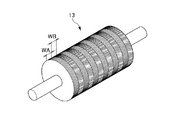
図3は、ロール版13を示す斜視図である。ロール版13は、中心軸方向に、パターン位相差フィルム1の右目用の領域A及び左目用の領域Bにそれぞれ対応するリング状の領域WA、WBが順次交互に形成される。また各領域WA、WBには、それぞれ対応する凹凸形状が形成される。
FIG. 3 is a perspective view showing the
図4は、このロール版13の製造工程の説明に供するフローチャートである。ロール版13は、母材の周囲に、シート状のマスクを巻き付けてラビングを繰り返すことにより作成される。このためこの製造工程では、初めに、ロール版13の母材にマスクがセットされる(ステップSP1−SP2)。
FIG. 4 is a flowchart for explaining the manufacturing process of the
ここでロール版13は、周囲を研磨した銅による円筒形状のベース材に、ニッケル膜を成膜して母材21が形成される。なおニッケル膜にリンを含有させると共に、凹凸形状を作成した後に、熱処理による後処理を適用して、表面の硬度を向上させるようにしても良い。またニッケルに代えてクロム、チタン等を適用しても良く、さらにはポリイミドを適用しても良い。
Here, in the
図5は、マスクを示す平面図である。マスク22は、母材21の側面を囲む大きさに全体が設定され、ストライプ状にスリットが形成される。ここでパターン位相差フィルム1は、右目用の領域A及び左目用の領域Bが同一幅Wにより密接して順次作成されており、これに対応してマスク22は、幅Wによるスリット22Aが、間隔Wだけ間をあけて、ロール版13の軸方向に対応するスリット22Aの幅方向に繰り返し形成される。またマスク22は、スリット22Aの長さLが、ロール版13の周囲の長さに比して充分に短い長さに設定され、所定間隔だけ間を空けて、スリット22Aがその長さ方向に繰り返し形成される。また偶数列と奇数列とでほぼL/2だけ長さ方向にシフトしてスリット22Aが配置され、これによりスリット22Aが千鳥に配置される。この間隔を空けたスリット22Aの長さ方向の配置により、またスリット22Aの千鳥の配置により、一連のラビングの処理において、マスク22に充分な強度を確保し、精度よく凹凸形状を作成することができる。なおマスク22は、ステンレス材、アルミニウム材等によるシート材をエッチング処理等して作成することができる。
FIG. 5 is a plan view showing the mask. The
図6に示すように、この工程では、スリット22Aの延長方向が、母材21の円周方向となるように、母材21の周囲にマスク22を貼り付けて配置する。続いてラビング処理用のロール等を用いて、母材21の全面をラビング処理する(図4、ステップSP3)。これによりこの工程は、パターン位相差フィルム1に設ける右目用の領域A及び左目用の領域Bのうちの1方の領域について、ロール版13の対応する領域の一部にラビング処理による凹凸形状を部分的に形成する。なおこの図6においては、このラビング処理により作成される凹凸形状の延長方向を矢印Aにより示す。またこの図6においては、図7との対比により、後述するマスク22のシフトを明確にするように、マスク22を幅狭に強調して示す。
As shown in FIG. 6, in this step, the
続いてこの工程では、スリット22Aの延長方向にマスク22をL/2だけシフトさせ、ラビング処理を再度実行する(ステップSP4−SP5)。これによりこの工程は、パターン位相差フィルム1に設ける右目用の領域A及び左目用の領域Bのうちの1方の領域について、当初のラビング処理で残る領域をラビング処理し、この1方の領域に対応する全ての領域に凹凸形状を形成する。
Subsequently, in this step, the
続いてこの工程では、スリット22Aの幅方向にマスク22をWだけシフトさせ、ラビング処理し、これにより図7において矢印Bにより示すように、先の1方の領域とは直交する方向に凹凸形状が連続するように凹凸形状を作成する(ステップSP6ーSP7)。また続いてスリット22Aの延長方向にマスク22をL/2だけシフトさせ、ラビング処理を再度実行する(ステップSP8ーSP9)。これによりこの工程は、ロール版13の残りの領域に凹凸形状を形成する。
Subsequently, in this step, the
これによりこの実施の形態では、1つのマスクを使用したラビング処理の繰り返しにより、簡易かつ短時間でロール版の凹凸形状を作成することができる。従ってこのロール版の使用により、従来に比してパターン位相差フィルムを容易かつ大量に作製することができる。 As a result, in this embodiment, the concavo-convex shape of the roll plate can be created easily and in a short time by repeating the rubbing process using one mask. Therefore, by using this roll plate, a pattern retardation film can be produced easily and in a large amount as compared with the prior art.
またスリットを長手方向に繰り返し作成するようにして、この長手方向にもマスクをシフトさせてラビングを繰り返すことにより、マスクの強度を充分に確保して、精度の高いラビング処理を繰り返すことができる。 In addition, by repeatedly creating the slit in the longitudinal direction and shifting the mask in the longitudinal direction and repeating the rubbing, the strength of the mask can be sufficiently secured and the rubbing process with high accuracy can be repeated.
〔他の実施の形態〕
以上、本発明の実施に好適な具体的な構成を詳述したが、本発明は、本発明の趣旨を逸脱しない範囲で、上述の実施の形態の構成を種々に変更することができる。
[Other Embodiments]
As mentioned above, although the specific structure suitable for implementation of this invention was explained in full detail, this invention can change the structure of the above-mentioned embodiment variously in the range which does not deviate from the meaning of this invention.
すなわち上述の実施の形態では、幅Wのスリットを、間隔Wだけ間を空けて、その幅方向に繰り返し作成してマスクを作成する場合について述べたが、本発明はこれに限らず、例えば幅Wのスリットを、間隔Wの奇数倍の間隔3W、5Wだけ間を空けて、その幅方向に繰り返しスリットを作成してマスクとしても良い。なおこの場合、間隔を大きくした分だけ、幅方向のシフトを繰り返して、ラビング処理することが必要になる。 That is, in the above-described embodiment, the case where the mask is formed by repeatedly creating the slit having the width W by the interval W and repeatedly forming the slit in the width direction is not limited thereto. It is also possible to use a slit of W as a mask by making a gap 3W, 5W, which is an odd multiple of the interval W, and repeatedly forming slits in the width direction. In this case, it is necessary to perform the rubbing process by repeating the shift in the width direction as much as the interval is increased.
また上述の実施の形態では、スリットを千鳥に配置する場合について述べたが、本発明はこれに限らず、実用上充分にスリットの変形等を防止できる場合には、千鳥の配置を省略してスリットを整列させて配置しても良い。 In the above-described embodiment, the case where the slits are arranged in a staggered manner has been described. However, the present invention is not limited to this, and the arrangement of the staggered portions may be omitted if the deformation of the slits can be prevented practically. The slits may be aligned.
また上述の実施の形態では、円筒形状による母材を加工してロール版を作成する場合について述べたが、本発明はこれに限らず、円柱形状による母材を加工してロール版を作成しても良い。 Further, in the above-described embodiment, the case where the roll base is produced by processing the cylindrical base material is described. However, the present invention is not limited to this, and the roll base is produced by processing the base material having a cylindrical shape. May be.
また上述の実施形態では、母材の側面を囲む大きさによりマスクを作成する場合について述べたが、本発明はこれに限らず、各辺の長さを母材の全長及び又は円周長より短い長さに設定して、マスクを小型化しても良い。但しこの場合は、マスクを小型化した分だけ、マスクをシフトさせてロール版に係るラビン処理を繰り返すことが必要になる。 In the above-described embodiment, the case where the mask is created with the size surrounding the side surface of the base material has been described, but the present invention is not limited to this, and the length of each side is determined from the total length of the base material and / or the circumferential length. The mask may be reduced in size by setting it to a short length. In this case, however, it is necessary to shift the mask by the size of the mask and repeat the rabin process related to the roll plate.
また上述の実施の形態では、ロール版の外周に、リング状に、右目用の領域に係る凹凸形状の領域、左目用の領域に係る凹凸形状の領域を順次作製する場合について述べたが、本発明はこれに限らず、これと直交する方向である軸方向に延長するように、各凹凸形状の領域を形成するようにしても良い。なおこの場合に、母材に配置するマスクの向きを変更して対応することもできる。 Further, in the above-described embodiment, a case has been described in which an uneven region related to the right eye region and an uneven region related to the left eye region are sequentially formed on the outer periphery of the roll plate in a ring shape. The invention is not limited to this, and the uneven regions may be formed so as to extend in the axial direction, which is a direction orthogonal to the orthogonal direction. In this case, it is possible to change the orientation of the mask arranged on the base material.
また上述の実施の形態では、ロール版を使用して連続して凹凸形状を転写する場合について述べたが、本発明はこれに限らず、平板を使用する場合にも広く適用することができる。 Moreover, although the above-mentioned embodiment described the case where a concavo-convex shape was continuously transferred using a roll plate, the present invention is not limited to this and can be widely applied to the case of using a flat plate.
また上述の実施の形態では、液晶表示パネルの使用を前提としたパターン位相差フィルムを作製する場合について述べたが、本発明はこれに限らず、有機ELパネル、プラズマディスプレイパネルの使用を前提に、偏光フィルタを一体に設ける場合にも広く適用することができる。 In the above-described embodiment, the case where a pattern retardation film is prepared on the premise that a liquid crystal display panel is used has been described. However, the present invention is not limited to this, and the use of an organic EL panel and a plasma display panel is assumed. Also, the present invention can be widely applied when the polarizing filter is provided integrally.
1 パターン位相差フィルム
2 基材
3 配向膜
4 位相差層
5 紫外線硬化樹脂
10 製造装置
11 供給リール
12、19 ダイ
13 ロール版
14 加圧ローラ
15、17 紫外線照射装置
16 剥離ローラ
18 巻き取りリール
21 母材
22 マスク
22A スリット
DESCRIPTION OF
Claims (4)
前記パターン位相差フィルムは、
前記配向膜のパターニングにより、右目用の透過光に、対応する位相差を与える右目用の領域と、左目用の透過光に、対応する位相差を与える左目用の領域とが、それぞれ帯状に順次交互に形成され、
前記転写用金型は、
母材の表面に前記凹凸形状が形成されて作成され、
前記パターン位相差フィルムの作成方法は、
前記右目用又は左目用の領域の幅によるスリットが、前記スリットの幅方向に繰り返し作成されているシート状のマスクを、前記母材の表面に配置してラビング処理し、前記右目用又は左目用の領域に対応する凹凸形状を前記母材に作成する第1のラビング処理工程と、
前記スリットの幅だけ、前記マスクを前記スリットの幅方向にシフトさせるシフト工程と、
前記シフト工程による配置により、前記第1のラビング処理工程におけるラビング処理とは直交する方向に、前記母材をラビング処理し、前記左目用の領域又は前記右目用の領域に対応する凹凸形状を前記母材に作成する第2のラビング処理工程とを備える
ことを特徴とするパターン位相差フィルムの作成方法。 In the method of creating a pattern retardation film that forms an alignment film by transferring the uneven shape formed on the transfer mold to a transparent sheet material,
The pattern retardation film is
By patterning the alignment layer, a right-eye region that gives a corresponding phase difference to the transmitted light for the right eye and a left-eye region that gives a corresponding phase difference to the transmitted light for the left eye are sequentially formed in a band shape, respectively. Alternately formed
The transfer mold is
Created by forming the uneven shape on the surface of the base material,
The method of creating the pattern retardation film is as follows:
A sheet-like mask in which a slit according to the width of the region for the right eye or the left eye is repeatedly created in the width direction of the slit is disposed on the surface of the base material and rubbed, for the right eye or the left eye A first rubbing treatment step of creating an uneven shape corresponding to the region of the base material,
A shift step of shifting the mask in the width direction of the slit by the width of the slit;
By the arrangement by the shift process, the base material is rubbed in a direction orthogonal to the rubbing process in the first rubbing process, and the uneven shape corresponding to the left eye region or the right eye region is formed. And a second rubbing treatment step for producing a base material. A method for producing a patterned retardation film.
前記スリットの長手方向に、前記スリットがり返し作成され、
前記第1のラビング処理工程は、
前記母材に前記マスクを配置してラビング処理した後、前記スリットの長手方向に前記マスクをシフトさせてラビング処理し、
前記第2のラビング処理工程は、
前記シフト工程による配置により、前記第1のラビング処理工程におけるラビング処理とは直交する方向に、前記母材をラビング処理した後、前記スリットの長手方向に前記マスクをシフトさせてラビング処理する
ことを特徴とする請求項1に記載のパターン位相差フィルムの作成方法。 The mask is
The slit is created repeatedly in the longitudinal direction of the slit,
The first rubbing treatment step includes
After the rubbing treatment by arranging the mask on the base material, the rubbing treatment is performed by shifting the mask in the longitudinal direction of the slit,
The second rubbing treatment step includes
After the base material is rubbed in a direction orthogonal to the rubbing treatment in the first rubbing treatment step, the mask is shifted in the longitudinal direction of the slit to perform the rubbing treatment by the arrangement in the shift step. The method for producing a patterned retardation film according to claim 1, wherein:
前記パターン位相差フィルムは、
前記配向膜のパターニングにより、右目用の透過光に、対応する位相差を与える右目用の領域と、左目用の透過光に、対応する位相差を与える左目用の領域とが、それぞれ帯状に順次交互に形成され、
前記パターン位相差フィルム作成用金型は、
母材の表面に前記凹凸形状が形成されて作成され、
前記パターン位相差フィルム作成用金型の作成方法は、
前記右目用又は左目用の領域の幅によるスリットが、前記スリットの幅方向に繰り返し作成されているシート状のマスクを、前記母材の表面に貼り付けてラビング処理し、前記右目用又は左目用の領域に対応する凹凸形状を前記母材に作成する第1のラビング処理工程と、
前記スリットの幅だけ、前記マスクを前記スリットの幅方向にシフトさせるシフト工程と、
前記シフト工程による配置により、前記第1のラビング処理工程におけるラビング処理とは直交する方向に、前記母材をラビング処理し、前記左目用の領域又は前記右目用の領域に対応する凹凸形状を前記母材に作成する第2のラビング処理工程とを備える
ことを特徴とするパターン位相差フィルム作成用金型の作成方法。 A method of creating a mold for creating a pattern retardation film, which creates an alignment film of a pattern retardation film by transferring to a concavo-convex transparent sheet material formed on the surface,
The pattern retardation film is
By patterning the alignment layer, a right-eye region that gives a corresponding phase difference to the transmitted light for the right eye and a left-eye region that gives a corresponding phase difference to the transmitted light for the left eye are sequentially formed in a band shape, respectively. Alternately formed
The mold for creating the pattern retardation film is
Created by forming the uneven shape on the surface of the base material,
The method for creating the mold for creating the pattern retardation film is as follows.
A sheet-like mask in which a slit having a width of the right-eye or left-eye region is repeatedly formed in the width direction of the slit is attached to the surface of the base material and rubbed, and the right-eye or left-eye A first rubbing treatment step of creating an uneven shape corresponding to the region of the base material,
A shift step of shifting the mask in the width direction of the slit by the width of the slit;
By the arrangement by the shift process, the base material is rubbed in a direction orthogonal to the rubbing process in the first rubbing process, and the uneven shape corresponding to the left eye region or the right eye region is formed. And a second rubbing treatment step for producing a base material. A method for producing a mold for producing a pattern retardation film.
前記スリットの長手方向に、繰り返し作成され、
前記第1のラビング処理工程は、
前記母材に前記マスクを貼り付けてラビング処理した後、前記スリットの長手方向に前記マスクをシフトさせてラビング処理し、
前記第2のラビング処理工程は、
前記シフト工程による配置により、前記第1のラビング処理工程におけるラビング処理とは直交する方向に、前記母材をラビング処理した後、前記スリットの長手方向に前記マスクをシフトさせてラビング処理する
ことを特徴とする請求項3に記載のパターン位相差フィルム作成用金型の作成方法。 The mask is
In the longitudinal direction of the slit, repeatedly created,
The first rubbing treatment step includes
After the mask is pasted on the base material and rubbed, the mask is shifted in the longitudinal direction of the slit and rubbed.
The second rubbing treatment step includes
After the base material is rubbed in a direction orthogonal to the rubbing treatment in the first rubbing treatment step, the mask is shifted in the longitudinal direction of the slit to perform the rubbing treatment by the arrangement in the shift step. The method for producing a mold for producing a pattern retardation film according to claim 3.
Priority Applications (1)
| Application Number | Priority Date | Filing Date | Title |
|---|---|---|---|
| JP2011110848A JP2012242515A (en) | 2011-05-17 | 2011-05-17 | Manufacturing method of pattern phase difference film, and manufacturing method of metal mold for manufacturing pattern phase difference film |
Applications Claiming Priority (1)
| Application Number | Priority Date | Filing Date | Title |
|---|---|---|---|
| JP2011110848A JP2012242515A (en) | 2011-05-17 | 2011-05-17 | Manufacturing method of pattern phase difference film, and manufacturing method of metal mold for manufacturing pattern phase difference film |
Publications (1)
| Publication Number | Publication Date |
|---|---|
| JP2012242515A true JP2012242515A (en) | 2012-12-10 |
Family
ID=47464309
Family Applications (1)
| Application Number | Title | Priority Date | Filing Date |
|---|---|---|---|
| JP2011110848A Pending JP2012242515A (en) | 2011-05-17 | 2011-05-17 | Manufacturing method of pattern phase difference film, and manufacturing method of metal mold for manufacturing pattern phase difference film |
Country Status (1)
| Country | Link |
|---|---|
| JP (1) | JP2012242515A (en) |
Citations (3)
| Publication number | Priority date | Publication date | Assignee | Title |
|---|---|---|---|---|
| JP2006276849A (en) * | 2005-03-03 | 2006-10-12 | Fuji Photo Film Co Ltd | Liquid crystal cell and liquid crystal display apparatus |
| JP2010152296A (en) * | 2008-09-22 | 2010-07-08 | Sony Corp | Method of manufacturing retardation plate |
| JP2011029161A (en) * | 2009-06-26 | 2011-02-10 | Sumitomo Chemical Co Ltd | Three-dimensional display device |
-
2011
- 2011-05-17 JP JP2011110848A patent/JP2012242515A/en active Pending
Patent Citations (3)
| Publication number | Priority date | Publication date | Assignee | Title |
|---|---|---|---|---|
| JP2006276849A (en) * | 2005-03-03 | 2006-10-12 | Fuji Photo Film Co Ltd | Liquid crystal cell and liquid crystal display apparatus |
| JP2010152296A (en) * | 2008-09-22 | 2010-07-08 | Sony Corp | Method of manufacturing retardation plate |
| JP2011029161A (en) * | 2009-06-26 | 2011-02-10 | Sumitomo Chemical Co Ltd | Three-dimensional display device |
Similar Documents
| Publication | Publication Date | Title |
|---|---|---|
| EP2942667B1 (en) | Patterning method using imprint mold | |
| JPWO2013031802A1 (en) | Pattern retardation film manufacturing method, pattern retardation film, and image display device | |
| JP5810735B2 (en) | Method for producing pattern retardation film and method for producing optical film | |
| JP5418559B2 (en) | Pattern retardation film manufacturing method and mask | |
| JP2012242515A (en) | Manufacturing method of pattern phase difference film, and manufacturing method of metal mold for manufacturing pattern phase difference film | |
| JP2013015754A (en) | Production method of patterned retardation film | |
| JP2013140306A (en) | Manufacturing method of pattern retardation film | |
| JP2012242773A (en) | Manufacturing method of pattern phase difference film, and manufacturing method of metal mold for manufacturing pattern phase difference film | |
| JP2008309963A (en) | Liquid crystal display device equipped with microlens array | |
| JP6064627B2 (en) | Manufacturing method of optical film | |
| JP2012247508A (en) | Manufacturing method of pattern phase difference film, and manufacturing method of metal mold for manufacturing pattern phase difference film | |
| JP2013015753A (en) | Production method of patterned retardation film | |
| JP5974604B2 (en) | Method for producing pattern retardation film | |
| JP6156017B2 (en) | Pattern retardation film manufacturing method, exposure apparatus and mask | |
| JP2014010220A (en) | Optical film, image display device and mold for producing optical film | |
| JP2014219596A (en) | Production method of optical film | |
| JP6048187B2 (en) | Pattern retardation film and image display device | |
| JP2012247509A (en) | Manufacturing method of pattern phase difference film, and manufacturing method of metal mold for manufacturing pattern phase difference film | |
| JP2014182200A (en) | Production method of optical film | |
| JP2013120348A (en) | Manufacturing method of mold for manufacturing pattern retardation film, and manufacturing method of pattern retardation film | |
| JP2012242518A (en) | Manufacturing method of pattern phase difference film, and manufacturing method of metal mold for manufacturing pattern phase difference film | |
| JP5594334B2 (en) | Pattern retardation film, image display device, mold for producing pattern retardation film, and method for producing pattern retardation film | |
| JP2015049389A (en) | Production method of optical film, exposure apparatus, and mask | |
| JP6136665B2 (en) | Process for producing pattern retardation film, mask, and roll body of pattern retardation film | |
| JP6155767B2 (en) | Pattern retardation film manufacturing method and pattern retardation film exposure apparatus |
Legal Events
| Date | Code | Title | Description |
|---|---|---|---|
| A621 | Written request for application examination |
Free format text: JAPANESE INTERMEDIATE CODE: A621 Effective date: 20140317 |
|
| A977 | Report on retrieval |
Free format text: JAPANESE INTERMEDIATE CODE: A971007 Effective date: 20141210 |
|
| A131 | Notification of reasons for refusal |
Free format text: JAPANESE INTERMEDIATE CODE: A131 Effective date: 20141216 |
|
| A02 | Decision of refusal |
Free format text: JAPANESE INTERMEDIATE CODE: A02 Effective date: 20150421 |