JP2012242023A - Hot water storage tank unit - Google Patents
Hot water storage tank unit Download PDFInfo
- Publication number
- JP2012242023A JP2012242023A JP2011114083A JP2011114083A JP2012242023A JP 2012242023 A JP2012242023 A JP 2012242023A JP 2011114083 A JP2011114083 A JP 2011114083A JP 2011114083 A JP2011114083 A JP 2011114083A JP 2012242023 A JP2012242023 A JP 2012242023A
- Authority
- JP
- Japan
- Prior art keywords
- hot water
- storage tank
- water storage
- tank unit
- legs
- Prior art date
- Legal status (The legal status is an assumption and is not a legal conclusion. Google has not performed a legal analysis and makes no representation as to the accuracy of the status listed.)
- Granted
Links
Images


Landscapes
- Details Of Fluid Heaters (AREA)
Abstract
Description
本発明の実施形態はヒートポンプ給湯機や電気温水器等の貯湯タンクユニットに関する。 Embodiments described herein relate generally to a hot water storage tank unit such as a heat pump water heater or an electric water heater.
一般に、電気温水器は、例えば夜間割引の安価な電力により、貯湯タンク内に配設された電気ヒータを通電加熱することにより貯湯タンク内の貯水を所要温度に加熱し、その温水を貯湯タンク内に貯湯する。 In general, an electric water heater heats the stored water in a hot water tank to a required temperature by energizing and heating an electric heater disposed in the hot water tank, for example, with cheap electricity at night discount, and the hot water is stored in the hot water tank. To store hot water.
また、電気ヒータに代えてヒートポンプ(冷凍サイクル)を用いたヒートポンプ給湯機は、例えば夜間割引の安価な電力等により、冷凍サイクルを駆動して貯湯タンク内の貯水を所要温度に加熱し、その温水を貯湯タンク内に貯湯する。 In addition, a heat pump water heater that uses a heat pump (refrigeration cycle) instead of an electric heater drives the refrigeration cycle to heat the stored water in the hot water storage tank to a required temperature by using, for example, cheap electricity at night discount, and the hot water In the hot water storage tank.
このヒートポンプ給湯機は、冷凍サイクルにより貯水を加熱するので、電気ヒータによる加熱よりもエネルギ効率がよく、電気入力に対する成績係数(COP)は3倍以上確保することが可能であり、ランニングコストの低減を図ることができる。 Since this heat pump water heater heats the stored water by the refrigeration cycle, it is more energy efficient than heating by an electric heater, and it is possible to secure a coefficient of performance (COP) of three times or more for electric input, reducing running costs. Can be achieved.
この種の従来の貯湯タンクでは、円筒状のタンクの底面に3本の支持脚を設け、この支持脚を、コンクリート製等の据付面にアンカーボルト等により固定して据え付けている(特許文献1参照)。 In this type of conventional hot water storage tank, three support legs are provided on the bottom surface of a cylindrical tank, and the support legs are fixed to an installation surface made of concrete or the like with an anchor bolt or the like (Patent Document 1). reference).
しかしながら、上記特許文献1記載の貯湯タンクでは、支持脚が3本であるので、荷扱い時や据付時に自立させたときに、3本の支持脚を結んで形成される三角形のいずれか1辺方向に変位荷重を受けて傾動した場合には、貯湯タンクが重い(例えば満水時で500〜700kg)ので、転倒する虞がある。
However, in the hot water storage tank described in
本発明は、このような事情を考慮してなされたもので、その目的は、転倒防止を図ることができる貯湯タンクユニットを提供することにある。 The present invention has been made in view of such circumstances, and an object of the present invention is to provide a hot water storage tank unit that can prevent overturning.
本実施形態の貯湯タンクユニットは、筐体と、この筐体内に収納され湯水を貯える貯湯タンクとを備えた貯湯タンクユニットにおいて、一端側が貯湯タンクに固着され、他端が筐体の下面よりも下方に突出する3本の主脚を有する。 The hot water storage tank unit of the present embodiment is a hot water storage tank unit that includes a housing and a hot water storage tank that is stored in the housing and stores hot water. One end of the hot water storage tank unit is fixed to the hot water storage tank, and the other end is lower than the lower surface of the housing. It has three main legs that protrude downward.
また、筐体の下面から下方へ突出する長さが主脚の突出長さよりも小さく形成され、かつ3本の主脚を結んで形成される三角形の外側に位置する補助脚と、を備えている。 And an auxiliary leg that is formed to have a length that protrudes downward from the lower surface of the housing to be smaller than a protruding length of the main leg, and is located outside the triangle formed by connecting the three main legs. Yes.
以下、本発明の実施形態を図面に基づいて説明する。なお、複数の図面中、同一または相当部分には同一符号を付している。 Hereinafter, embodiments of the present invention will be described with reference to the drawings. In addition, the same code | symbol is attached | subjected to the same or an equivalent part in several drawing.
(第1の実施形態)
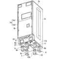
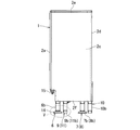
図1は、第1の実施形態に係る貯湯タンクユニットの底面図、図2は同貯湯タンクユニットの正面図、図3は同貯湯タンクユニットの底面側を仰視したときの仰視図、図4は同貯湯タンクユニットの側面図、図5は図4のV部拡大図、図6は同貯湯タンクユニットの分解斜視図である。この貯湯タンクユニット1は例えばヒートポンプ給湯機に用いられるものであって、これらの図に示すように貯湯タンクユニット1は、例えば板金製角筒状の筐体2と、この筐体2内に収容されるステンレス等金属製円筒状の貯湯タンク3とを具備している。
(First embodiment)
1 is a bottom view of the hot water storage tank unit according to the first embodiment, FIG. 2 is a front view of the hot water storage tank unit, FIG. 3 is a top view when the bottom surface side of the hot water storage tank unit is looked up, and FIG. 5 is a side view of the hot water storage tank unit, FIG. 5 is an enlarged view of a portion V in FIG. 4, and FIG. 6 is an exploded perspective view of the hot water storage tank unit. The hot water
図6に示すように、筐体2は、板金製の正面板2a、同,左右一対の側板2b,2c、同,背面板2d、同,天板2eおよび底板2fを有する。さらに、正面板2aは上部正面板2a1と下部正面板2a2とに分割されている。左右一対の側板2b,2cは、その図6中、上端と左右両側端に、内方へほぼ直角に折曲形成された取付代Pを形成している。同じく、天板2eの正面側と背面側の外縁部に所要の取付代Rをそれぞれ形成し、これら取付代P,Rには図示省略の複数の取付ねじをねじ込むためのねじ孔をそれぞれ形成している。
As shown in FIG. 6, the
一方、図6に示すように、底板2fは、その矩形外周縁部の各辺に、図中上方へ若干立ち上がる矩形環状の側壁2f1を形成しており、この側壁2f1の内側にて、底板2f上に、下部正面板2a2、一対の側板2b,2cおよび背面板2dを角筒状に載置し、一対の側板2b,2cの各取付代Pの複数のねじ孔内に取付ねじをそれぞれねじ込むことにより、まず、上端開口の角筒状に組み付けている。この後、下部正面板2a2の上端上に、上部正面板2a1を載置し、この上部正面板2a1の左右両側面を、左右一対の側板2b,2cの取付代Pの上部側面に密着させ、この取付代Pの複数のねじ孔に取付ねじをねじ込み、組み付けている。こうして角筒状に形成された上面開口端上には天板2eが載置され、天板2eの取付代Rの複数のねじ孔内に取付ねじをそれぞれねじ込み、有蓋有底の角筒状の筐体2を形成する。
On the other hand, as shown in FIG. 6, the
貯湯タンク3は、その内部に、例えば水道水等の水が給水され、貯湯タンク3内の水は、貯湯タンクユニット1とは別に設けられた図示しないヒートポンプユニットで加熱される。このヒートポンプユニットで加熱された温水は貯湯タンク3内に貯湯される。貯湯タンク3は、正面板2aの内面に対向する正面側の外面に、水路部品4、電気部品箱5および制御弁等に給電する給電線等の配線を配設している。
The hot
水路部品4は、例えば水道水を貯湯タンク3内に給水する給水管や、貯湯タンク3内の湯水を図示省略の給水端末に給湯する給湯管を含む。電気部品箱5は、通電を制御する図示しない制御装置や操作盤等の電気部品を具備している。
The water channel component 4 includes, for example, a water supply pipe for supplying tap water into the hot
このように貯湯タンク3の正面側は、水路部品4や電気部品箱5が配設されているので、その分、正面以外の左右側面側や背面側よりも重くなっている。
Thus, since the water channel component 4 and the electrical component box 5 are disposed on the front side of the hot
そして、図7に示すように貯湯タンク3は、その下部外面に、3本の主脚6,7,8の一端である図中上端と、3本の補助脚9,10,11の一端である図中上端とを、取付部材12,12,…によりそれぞれ固着している。
As shown in FIG. 7, the hot
主脚6,7,8は、例えば横断面L形の型鋼により形成された上部主脚6a,7a,8aと、これら上部主脚6a,7a,8aと上下方向に重なるように形成され、横断面コ字形で側方の1面が開口した下部主脚6b,7b,8bとを有する。各下部主脚6b,7b,8bは、その開口を正面側に向けて開口させている。
The
すなわち、各上部主脚6a,7a,8aは、その一端(図7では上端)を、取付部材12,12,12により貯湯タンク3の下部外周面に固着している。
That is, each upper
各上部主脚6a,7a,8aは、その図中下端に、例えば矩形平板状の取付フランジ13,13,13を溶接等により固着している。各取付フランジ13,13,13は、図示省略の複数の取付ねじにねじ結合されるねじ孔を形成しており、底板2fの内底面(図7では上面)上に載置される。
Each upper
各下部主脚6b,7b,8bは、その上面に、取付ねじの軸部を挿通する複数の挿通孔をそれぞれ形成しており、これら挿通孔に対応する位置にて底板2fにも挿通孔をそれぞれ形成している。
Each lower
すなわち、各下部主脚6b,7b,8bの上面の下方側から上面の各挿通孔内に取付ねじの軸部を挿通し、さらに、底板2fの各挿通孔を挿通して取付フランジ13のねじ孔にねじ込むことにより、各上部主脚6a,7a,8aに、各下部主脚6b,7b,8bを一体的に固着している。各下部主脚6b,7b,8bの底面には、固定脚14をそれぞれ配設している。各固定脚14は、その底部に、例えばコンクリート製の据付面に埋設されたアンカーボルトのねじ軸部を挿通させる挿通孔を形成し、このアンカーボルトのねじ軸部に締結ナットを締結することにより、据付面に固定され、据え付けられる。
That is, the shaft portion of the mounting screw is inserted into the insertion hole on the upper surface from the lower side of the upper surface of each lower
各補助脚9,10,11も、主脚6,7,8と同様に、底板2fよりも図中上側のL形の型鋼よりなり、取付フランジ13を有する上部補助脚9a,10a,11aと、図中下側の横断面コ字形で側方の1面が開口した下部補助脚9b,10b,11bとを有し、図示省略の取付ねじにより一体的に同心状に固着するようになっている。
Similarly to the
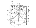
図1は、これら3本の主脚6,7,8と、3本の補助脚9,10,11との位置関係を示す貯湯タンクユニット1の底面図である。
FIG. 1 is a bottom view of the hot
図1に示すように、3本の主脚6,7,8は、その下部主脚6b,7b,8bの底面の中心oa,ob,oc同士を直線により順次結んだときに、三角形tをなすように配置されている。すなわち、3本の主脚6,7,8は、筐体2の正面板2a側の幅方向中部に下部主脚6bの底面中心oaが位置し、下部主脚7b,8bの底面中心ob,ocが背面側2d側の両端側、すなわち、左右一対の側板2b,2c側に位置するように配置されている。この三角形tは、底板2fに垂直方向に投影された貯湯タンク3の外周面をなす円にほぼ内接する三角形であればよく、正三角形でもよい。すなわち、3本の主脚6,7,8は、その下部主脚6b,7b,8bの底面中心oa,ob,ocがこれら底面中心oa,ob,oc同士を直線により結んだときに形成される正三角の各頂点に位置するように配置される。
As shown in FIG. 1, the three
そして、3本の補助脚9,10,11は、その各下部補助脚9b,10b,11bの底面中心od,oe,ofが三角形tの外側に位置し、かつ三角形tの各辺a,b,cをそれぞれ2等分し、垂直方向に交差する垂直2等分線d,e,f上に位置するように配設されている。なお、図1中、gは底板2fの強度を補強する補強リブである。また、図1〜図3,図8中、符号15は、貯湯タンクユニット1内の給水管や給湯管等の配管に接続される配管接続部であり、外部の給水管や給湯管等と接続されるようになっている。
The three
また、図4,図5に示すように、各補助脚9,10,11は、その底板2fよりも下方へ突出する各下部補助脚9b,10b,11bの突出長さを、各下部主脚6b,7b,8bの突出長さよりも所定長α短く形成している。
As shown in FIGS. 4 and 5, each of the
したがって、このように構成された貯湯タンクユニット1を、荷扱い時や据付面への据付時等により、自立させたときには、3本の主脚6〜8が自立面や据付面にそれぞれ接面するので、仮に自立面や据付面が傾斜している場合でも自立させることができる。
Therefore, when the hot water
そして、このような貯湯タンクユニット1の自立時に、例えば3本の支持脚6〜8の中間部方向、すなわち、上記三角形tのいずれか1辺方向に変位荷重を受けて貯湯タンクユニット1が万一傾動した場合には、その変位荷重が負荷される側にある補助脚9,10,11の少なくともいずれかが自立面や据付面に接面し、貯湯タンクユニット1を支持するので、その転倒の防止を図ることができる。すなわち、貯湯タンクユニット1の揺れの方向が予測できない地震時における貯湯タンクユニット1の転倒防止を図ることができる。
When such a hot water
さらに、各補助脚9,10,11は、その上部補助脚9a,10a,11aの一端(上端)を貯湯タンク3の下部外周面に固着しており、筐体2の底板2fのみに固着されているのではないので、この底板2fおよびこの底板2fに組み付けられている正面板2a、側板2b,2c、背面板2dおよび天板2e等の筐体2の変形の防止または低減を図ることができる。
Further, each
また、各下部補助脚9b,10b,11bの長さは、下部主脚6b,7b,8bの長さよりも短いので、現地での据付作業時の平坦度出しの支障にならない。
Moreover, since the length of each lower
さらに、貯湯タンクユニット1では、その正面側の底板2fの幅方向中間部に主脚6を配設する一方、背面側の底板2fの幅方向両側には左右の主脚7,8を配設し、これら主脚6〜8同士を結ぶ三角形のほぼ中心に、貯湯タンク3の重心を配置しているので、貯湯タンクユニット1の重心を安定させることができる。これにより、貯湯タンクユニット1の転倒の虞をさらに低減できる。また、筐体2の正面側の底板2fには、その幅方向中間部に配設された主脚6の1本しか設けていないので、筐体2の正面側に設けた配管接続部15に接続される図示省略の配管の引き回しの際に主脚6が干渉するのを低減できる。このために、配管引き回しの作業性の向上を図ることができる。
Further, in the hot water
なお、貯湯タンクユニット1の据付完了後には、補助脚9,10,11の底面と自立面との間にスペーサを介在させる等により、補助脚と自立面間の隙間をなくするようにしてもよく、これによれば、貯湯タンクユニットの自立をさらに安定させることができる。
After the hot water
(第2の実施形態)
図8は第2の実施形態に係る貯湯タンクユニット1Aの底面を示す。この図8に示すように貯湯タンクユニット1Aは、上記第1の実施形態に係る貯湯タンクユニット1の背面板2d側に設けた補助脚10を省略した点に主な特徴を有する。
(Second Embodiment)
FIG. 8 shows the bottom surface of the hot water
すなわち、貯湯タンクユニット1Aは、図8に示すように、底板2fに垂直方向に投影された貯湯タンク3の外周面をなす円Sに内接する五角形Qの各頂点に、3本の主脚6〜8と2本の補助脚9,11の各底面中心oa,od,ob,oc,ofが一致するように3本の主脚6〜8と、2本の補助脚9,11を配設している。
That is, as shown in FIG. 8, the hot water
すなわち、通常、貯湯タンクユニット1Aは、その据付時には、背面板2d側を、家屋の外壁面に接するように配置する場合が多い。この場合は、貯湯タンクユニット1Aが地震等により家屋の外壁面側に傾動しても、その傾動は家屋の外壁面により支持されるので、転倒を防止できるためである。これにより、第1の実施形態の効果に加えて、背面板2d側の補助脚10を削除してコストの低減を図ることができる。
That is, normally, the hot water
(第3の実施形態)
図9は第3の実施形態に係る貯湯タンクユニット1Bの要部拡大図である。図9に示すようにこの貯湯タンクユニット1Bは、上記第1,第2の実施形態における下部補助脚9b〜11bの長さを調節可能に構成した点に特徴がある。
(Third embodiment)
FIG. 9 is an enlarged view of a main part of a hot water
すなわち、補助脚9〜11は、その下部補助脚9b〜11bを、図9中、上部の横断面形状がコ字状の無底本体部16と、図9中下部の有底コ字状の可動底部17とに分割し、本体部16の図9中下端部に、可動底部17を、軸方向に摺動可能に外嵌させている。
That is, the
本体部16は、その外嵌部におけるコ字状構造の一対の対向側面に、複数の止めボルト18,18のねじ部にねじ結合されるねじ孔(図示省略)を図9中、左右方向に並設している。
The
一方、可動底部17は、その外嵌部におけるコ字状構造の一対の対向側面に、各止めボルト18のねじ部の直径よりも若干大きく、かつ頭部18aよりも小さく、軸方向(図9中縦方向)に長い複数の長孔19,19をそれぞれ形成している。
On the other hand, the
したがって、可動底部17の高さ(突出長)を適宜調節してから、止めボルト18,18を堅く締め付け、本体部16に固定することにより、可動底部17の高さを適宜調節できる。
Therefore, the height of the
このために、貯湯タンクユニット1Bの据付が完了するまでは、可動底部17を上方に位置させて補助脚9〜11の底板2fからの突出長さを、3本の主脚6〜8の突出長さよりも小さくし、その荷扱い時や据付時等において、自立させる場合には、まず、3本の主脚6〜8により自立面に接面させる。そして、貯湯タンクユニット1Bの据付が完了したら、補助脚9〜11の各可動底部17の高さ(突出長)をそれぞれ調節して、これら可動底部17の底面を自立面に接面させる。
For this reason, until the installation of the hot water
これにより、3本の主脚6〜8と、2本または3本の補助脚9〜11の全部を自立面にそれぞれ接面させることができる。このために、これら主脚6〜8と補助脚9〜11により貯湯タンクユニット1Bを支持することができるので、その支持強度の向上を図ることができるうえに、転倒防止効果のさらなる向上を図ることができる。なお、上記各実施形態ではヒートポンプ給湯機の貯湯タンクユニットについて説明したが、本発明はこれに限定されるものではなく、電気温水器に適用してもよい。
As a result, the three
以上のように、各実施形態の貯湯タンクユニットは、筐体の下面から下方へ突出する長さが主脚の突出長さよりも小さく形成され、かつ3本の主脚を結んで形成される三角形の外側に位置する補助脚を備えたので、据付作業時の平坦度出しに支障を与えることなしに、貯湯タンクユニットの転倒防止を図ることができる。 As described above, the hot water storage tank unit of each embodiment is a triangle formed such that the length projecting downward from the lower surface of the housing is smaller than the projecting length of the main leg and connecting the three main legs. Since the auxiliary legs are provided outside, the hot water storage tank unit can be prevented from falling without hindering the flatness at the time of installation.
以上、本発明の幾つかの実施形態を説明したが、これらの実施形態は、例として提示したものであり、発明の範囲を限定することは意図していない。これら新規な実施形態は、その他の様々な形態で実施されることが可能であり、発明の要旨を逸脱しない範囲で、種々の省略、置換え、変更を行うことができる。これら実施形態やその変形は、発明の範囲や要旨に含まれるとともに、特許請求の範囲に記載された発明とその均等の範囲に含まれる。 As mentioned above, although several embodiment of this invention was described, these embodiment is shown as an example and is not intending limiting the range of invention. These novel embodiments can be implemented in various other forms, and various omissions, substitutions, and changes can be made without departing from the scope of the invention. These embodiments and modifications thereof are included in the scope and gist of the invention, and are included in the invention described in the claims and the equivalents thereof.
1,1A,1B…貯湯タンクユニット、2…筐体、3…貯湯タンク、6,7,8…主脚、6a,7a,8a…上部主脚、6b,7b,8b…下部主脚、9,10,11…補助脚、9a,10a,11a…上部補助脚、9b,10b,11b…下部補助脚、17…可動底部、18…止めボルト、19…長孔、d,e,f…垂直2等分線、oa,ob,oc…下部主脚6b,7b,8bの底面中心、od,oe,of…下部補助脚9b,10b,11bの底面中心、t…三角形。
DESCRIPTION OF
Claims (4)
一端側が貯湯タンクに固着され、他端が上記筐体の下面よりも下方に突出する3本の主脚と、
上記筐体の下面から下方へ突出する長さが上記主脚の突出長さよりも小さく形成され、かつ上記3本の主脚を結んで形成される三角形の外側に位置する補助脚と、
を備えたことを特徴とする貯湯タンクユニット。 In a hot water storage tank unit comprising a housing and a hot water storage tank stored in the housing for storing hot water,
Three main legs with one end fixed to the hot water storage tank and the other end protruding downward from the lower surface of the housing;
An auxiliary leg that is formed to have a length that protrudes downward from the lower surface of the housing to be smaller than a protruding length of the main leg, and is located outside a triangle formed by connecting the three main legs;
A hot water storage tank unit characterized by comprising
上記補助脚は、前記筐体の正面側に配置された主脚の両側にそれぞれ配置されていることを特徴とする請求項1または2記載の貯湯タンクユニット。 The main legs are arranged such that one of them is located in the center in the width direction on the front side of the casing, and the other two are positioned on both ends in the width direction on the back side of the casing,
The hot water storage tank unit according to claim 1 or 2, wherein the auxiliary legs are arranged on both sides of a main leg arranged on the front side of the casing.
Priority Applications (1)
| Application Number | Priority Date | Filing Date | Title |
|---|---|---|---|
| JP2011114083A JP5759258B2 (en) | 2011-05-20 | 2011-05-20 | Hot water storage tank unit |
Applications Claiming Priority (1)
| Application Number | Priority Date | Filing Date | Title |
|---|---|---|---|
| JP2011114083A JP5759258B2 (en) | 2011-05-20 | 2011-05-20 | Hot water storage tank unit |
Publications (2)
| Publication Number | Publication Date |
|---|---|
| JP2012242023A true JP2012242023A (en) | 2012-12-10 |
| JP5759258B2 JP5759258B2 (en) | 2015-08-05 |
Family
ID=47463921
Family Applications (1)
| Application Number | Title | Priority Date | Filing Date |
|---|---|---|---|
| JP2011114083A Expired - Fee Related JP5759258B2 (en) | 2011-05-20 | 2011-05-20 | Hot water storage tank unit |
Country Status (1)
| Country | Link |
|---|---|
| JP (1) | JP5759258B2 (en) |
Cited By (2)
| Publication number | Priority date | Publication date | Assignee | Title |
|---|---|---|---|---|
| JP2015117845A (en) * | 2013-12-17 | 2015-06-25 | 三菱電機株式会社 | Hot water storage water heater |
| JP2016090145A (en) * | 2014-11-05 | 2016-05-23 | 三菱電機株式会社 | Hot water storage type water heater |
Citations (7)
| Publication number | Priority date | Publication date | Assignee | Title |
|---|---|---|---|---|
| JPS6115485Y2 (en) * | 1980-08-12 | 1986-05-14 | ||
| JPH02103657U (en) * | 1989-02-01 | 1990-08-17 | ||
| JPH0327152Y2 (en) * | 1983-06-25 | 1991-06-12 | ||
| JPH0532032Y2 (en) * | 1986-05-07 | 1993-08-17 | ||
| JP2877701B2 (en) * | 1994-08-05 | 1999-03-31 | 三洋電機株式会社 | Cold storage |
| JP2009222325A (en) * | 2008-03-18 | 2009-10-01 | Mitsubishi Electric Corp | Hot water storage type water heater |
| JP2011006098A (en) * | 2009-06-25 | 2011-01-13 | Mitsubishi Electric Corp | Apparatus packing device |
-
2011
- 2011-05-20 JP JP2011114083A patent/JP5759258B2/en not_active Expired - Fee Related
Patent Citations (7)
| Publication number | Priority date | Publication date | Assignee | Title |
|---|---|---|---|---|
| JPS6115485Y2 (en) * | 1980-08-12 | 1986-05-14 | ||
| JPH0327152Y2 (en) * | 1983-06-25 | 1991-06-12 | ||
| JPH0532032Y2 (en) * | 1986-05-07 | 1993-08-17 | ||
| JPH02103657U (en) * | 1989-02-01 | 1990-08-17 | ||
| JP2877701B2 (en) * | 1994-08-05 | 1999-03-31 | 三洋電機株式会社 | Cold storage |
| JP2009222325A (en) * | 2008-03-18 | 2009-10-01 | Mitsubishi Electric Corp | Hot water storage type water heater |
| JP2011006098A (en) * | 2009-06-25 | 2011-01-13 | Mitsubishi Electric Corp | Apparatus packing device |
Cited By (2)
| Publication number | Priority date | Publication date | Assignee | Title |
|---|---|---|---|---|
| JP2015117845A (en) * | 2013-12-17 | 2015-06-25 | 三菱電機株式会社 | Hot water storage water heater |
| JP2016090145A (en) * | 2014-11-05 | 2016-05-23 | 三菱電機株式会社 | Hot water storage type water heater |
Also Published As
| Publication number | Publication date |
|---|---|
| JP5759258B2 (en) | 2015-08-05 |
Similar Documents
| Publication | Publication Date | Title |
|---|---|---|
| KR101242050B1 (en) | Cable tray | |
| JP6428363B2 (en) | Hot water storage system | |
| JP5759258B2 (en) | Hot water storage tank unit | |
| EP2733429B1 (en) | Hot water storage tank unit | |
| JP4687522B2 (en) | Hot water storage tank unit | |
| JP5807739B2 (en) | Case mounting structure | |
| JP6420577B2 (en) | Hot water storage water heater | |
| JP2013087955A (en) | Water heater | |
| KR100293746B1 (en) | The Electric boiler of using the midnight electricity | |
| JP2010276229A (en) | Warm water type heating device | |
| KR20150062697A (en) | A prop of large meter room | |
| JP5874559B2 (en) | Seismic structure of hot water storage water heater | |
| EP2489789A2 (en) | Secondary pressurization water supply equipment | |
| JP5874422B2 (en) | Hot water storage water heater | |
| JP6447191B2 (en) | Hot water storage water heater | |
| JP2013170708A (en) | Liquid storage unit, reinforcing member, and water heater | |
| JP5010449B2 (en) | Building basic structure | |
| JP4167611B2 (en) | Through-wall combustor | |
| JP2012225628A (en) | Fixing structure of pump, and hot water supply system | |
| KR101602230B1 (en) | A heating dispenser | |
| JP5261444B2 (en) | Gas meter support | |
| JP2011007461A (en) | Storage type water heater | |
| JP2008101836A (en) | Storage water heater | |
| JP2011033207A (en) | Hot-water unit | |
| KR101972543B1 (en) | Support for fixing pipe and integrated cradle using the same |
Legal Events
| Date | Code | Title | Description |
|---|---|---|---|
| A621 | Written request for application examination |
Free format text: JAPANESE INTERMEDIATE CODE: A621 Effective date: 20140402 |
|
| RD02 | Notification of acceptance of power of attorney |
Free format text: JAPANESE INTERMEDIATE CODE: A7422 Effective date: 20141107 |
|
| A521 | Written amendment |
Free format text: JAPANESE INTERMEDIATE CODE: A821 Effective date: 20141107 |
|
| A977 | Report on retrieval |
Free format text: JAPANESE INTERMEDIATE CODE: A971007 Effective date: 20141222 |
|
| A131 | Notification of reasons for refusal |
Free format text: JAPANESE INTERMEDIATE CODE: A131 Effective date: 20150113 |
|
| A521 | Written amendment |
Free format text: JAPANESE INTERMEDIATE CODE: A523 Effective date: 20150316 |
|
| TRDD | Decision of grant or rejection written | ||
| A01 | Written decision to grant a patent or to grant a registration (utility model) |
Free format text: JAPANESE INTERMEDIATE CODE: A01 Effective date: 20150519 |
|
| A61 | First payment of annual fees (during grant procedure) |
Free format text: JAPANESE INTERMEDIATE CODE: A61 Effective date: 20150605 |
|
| R150 | Certificate of patent or registration of utility model |
Ref document number: 5759258 Country of ref document: JP Free format text: JAPANESE INTERMEDIATE CODE: R150 |
|
| R250 | Receipt of annual fees |
Free format text: JAPANESE INTERMEDIATE CODE: R250 |
|
| LAPS | Cancellation because of no payment of annual fees |