JP5874559B2 - Seismic structure of hot water storage water heater - Google Patents
Seismic structure of hot water storage water heater Download PDFInfo
- Publication number
- JP5874559B2 JP5874559B2 JP2012162538A JP2012162538A JP5874559B2 JP 5874559 B2 JP5874559 B2 JP 5874559B2 JP 2012162538 A JP2012162538 A JP 2012162538A JP 2012162538 A JP2012162538 A JP 2012162538A JP 5874559 B2 JP5874559 B2 JP 5874559B2
- Authority
- JP
- Japan
- Prior art keywords
- case
- plate
- hot water
- water storage
- storage tank
- Prior art date
- Legal status (The legal status is an assumption and is not a legal conclusion. Google has not performed a legal analysis and makes no representation as to the accuracy of the status listed.)
- Active
Links
- XLYOFNOQVPJJNP-UHFFFAOYSA-N water Substances O XLYOFNOQVPJJNP-UHFFFAOYSA-N 0.000 title claims description 117
- 230000003014 reinforcing effect Effects 0.000 claims description 57
- 238000007689 inspection Methods 0.000 claims description 3
- 239000002184 metal Substances 0.000 description 48
- 238000009434 installation Methods 0.000 description 5
- 230000002787 reinforcement Effects 0.000 description 5
- 230000004048 modification Effects 0.000 description 4
- 238000012986 modification Methods 0.000 description 4
- 239000011810 insulating material Substances 0.000 description 2
- 238000009413 insulation Methods 0.000 description 2
- 230000007423 decrease Effects 0.000 description 1
- 238000010438 heat treatment Methods 0.000 description 1
- 239000008236 heating water Substances 0.000 description 1
- 230000002093 peripheral effect Effects 0.000 description 1
- 238000003466 welding Methods 0.000 description 1
Images


Landscapes
- Details Of Fluid Heaters (AREA)
- Housings, Intake/Discharge, And Installation Of Fluid Heaters (AREA)
Description
本発明は、貯湯式給湯機の耐震構造に関する。 The present invention relates to an earthquake resistant structure of a hot water storage type hot water heater.
ヒートポンプ等の加熱手段により高温の湯を沸き上げて貯湯タンクに貯え、必要に応じて貯湯タンクから外部へ湯を給湯する貯湯式給湯機が広く用いられている。貯湯式給湯機の貯湯タンクユニットは、湯水を貯湯タンクと、保温性を確保するために貯湯タンクを覆う断熱材と、湯水を流入および流出させるための配管と、ポンプや弁等の機能部品と、給湯機を制御するための制御基板と、これらの構成機器を収納して保護する外装ケースと、外郭ケースを土台もしくは床面に固定するための脚とを備えた構造となっている。貯湯タンクユニットは、貯湯タンク内に湯水が貯留された状態では重量物となるが、大きな地震の際にも転倒しないように、十分な耐震性が求められる。 Hot water storage water heaters that boil high-temperature hot water by a heating means such as a heat pump and store it in a hot water storage tank and supply hot water from the hot water storage tank to the outside as needed are widely used. A hot water storage tank unit of a hot water storage type water heater is composed of a hot water storage tank, a heat insulating material covering the hot water storage tank to ensure heat insulation, piping for inflow and outflow of hot water, and functional parts such as a pump and a valve. The structure includes a control board for controlling the water heater, an exterior case for storing and protecting these components, and a leg for fixing the outer case to a base or a floor surface. The hot water storage tank unit is heavy when hot water is stored in the hot water storage tank, but is required to have sufficient earthquake resistance so that the hot water storage tank unit does not fall over in the event of a large earthquake.
特許文献1には、貯湯タンクユニットの外郭ケースの上端部が連結部材を用いて構造物に固定され、外郭ケースの上端部の内部には該上端部の機械的強度を補強するための補強構造体が配置されており、補強構造体は外郭ケースの上端部を貯湯タンクから延びる給湯管の基部に連結するように構成されたものが開示されている。 In Patent Document 1, the upper end portion of the outer case of the hot water storage tank unit is fixed to a structure using a connecting member, and the reinforcing structure for reinforcing the mechanical strength of the upper end portion is provided inside the upper end portion of the outer case. There is disclosed a structure in which a body is disposed, and the reinforcing structure is configured to connect the upper end portion of the outer case to the base portion of the hot water supply pipe extending from the hot water storage tank.
特許文献1に開示された構成では、貯湯タンクの上部が補強構造体を介して外郭ケース上部に連結されているため、貯湯タンク内の高温の湯の熱が補強構造体を介して外郭ケースや連結部材に伝熱し、外気へ放熱してしまう。このため、貯湯タンクの保温性能が低下する。 In the configuration disclosed in Patent Document 1, since the upper part of the hot water storage tank is connected to the upper part of the outer case through the reinforcement structure, the heat of the hot water in the hot water storage tank is Heat is transferred to the connecting member and radiated to the outside air. For this reason, the heat retention performance of the hot water storage tank decreases.
本発明は、上述のような課題を解決するためになされたもので、貯湯タンクの保温性能を損なうことなく、耐震性能を向上することのできる貯湯式給湯機の耐震構造を提供することを目的とする。 The present invention has been made to solve the above-described problems, and an object thereof is to provide a seismic structure for a hot water storage hot water heater capable of improving the seismic performance without impairing the heat insulation performance of the hot water storage tank. And
本発明に係る貯湯式給湯機の耐震構造は、貯湯タンクを内蔵する貯湯タンクユニットの外郭ケースの上面を形成するケース上面板と、ケース上面板の裏面に配置され、貯湯タンクに接触しない複数の補強部材と、ケース上面板と、外部の構造体とを連結する上部振れ止め部材と、を備え、上部振れ止め部材の一端は、ケース上面板と補強部材とに固定可能であり、上部振れ止め部材の他端は、構造体に固定可能であり、外郭ケースは、正面を形成するケース正面板と、側面を形成するケース側面板と、背面を形成するケース背面板とを有し、ケース正面板は、点検時に開閉可能であり、補強部材は、ケース正面板の上辺に並行して位置するケース上面板の辺の近傍には配置されず、ケース背面板の上辺に並行して位置するケース上面板の辺の近傍と、ケース側面板の上辺に並行して位置するケース上面板の辺の近傍とに配置されているものである。
また、本発明に係る貯湯式給湯機の耐震構造は、貯湯タンクを内蔵する貯湯タンクユニットの外郭ケースの上面を形成するケース上面板と、ケース上面板の裏面に配置され、貯湯タンクに接触しない複数の補強部材と、ケース上面板と、外部の構造体とを連結する上部振れ止め部材と、を備え、上部振れ止め部材の一端は、ケース上面板と補強部材とに固定可能であり、上部振れ止め部材の他端は、構造体に固定可能であり、外郭ケースは、正面を形成するケース正面板と、側面を形成するケース側面板と、背面を形成するケース背面板とを有し、補強部材は、下方に突出するリブを有し、ケース側面板とケース背面板との一方または両方の近傍にリブが配置されているものである。
The seismic structure of the hot water storage type hot water heater according to the present invention includes a case upper surface plate that forms the upper surface of the outer case of the hot water storage tank unit that houses the hot water storage tank, and a plurality of surfaces that are disposed on the back surface of the case upper surface plate and do not contact the hot water storage tank . An upper steadying member that connects the reinforcing member, the case upper surface plate, and an external structure; one end of the upper steadying member can be fixed to the case upper surface plate and the reinforcing member; the other end of the member, Ri fixable der in structure, the outer casing has a casing front plate forming a front, and a case side plate forming a side, and a case rear plate forming a rear case The front plate can be opened and closed at the time of inspection, and the reinforcing member is not disposed in the vicinity of the side of the case top plate located in parallel with the upper side of the case front plate, but is located in parallel with the upper side of the case back plate. On the side of the case top plate And near, Ru der those disposed in the vicinity of the sides of the case top plate located in parallel to the upper side of the case side plates.
Further, the seismic resistant structure of the hot water storage type hot water heater according to the present invention is arranged on the case upper surface plate forming the upper surface of the outer case of the hot water storage tank unit containing the hot water storage tank and the back surface of the case upper surface plate, and does not contact the hot water storage tank. A plurality of reinforcing members, a case top plate, and an upper steadying member that connects an external structure, and one end of the top steadying member can be fixed to the case top plate and the reinforcing member, The other end of the steady rest member can be fixed to the structure, and the outer case has a case front plate that forms the front, a case side plate that forms the side, and a case back plate that forms the back, The reinforcing member has a rib protruding downward, and the rib is disposed in the vicinity of one or both of the case side plate and the case back plate.
本発明によれば、貯湯タンクの保温性能を損なうことなく、耐震性能を向上することが可能となる。 ADVANTAGE OF THE INVENTION According to this invention, it becomes possible to improve seismic performance, without impairing the heat retention performance of a hot water storage tank.
以下、図面を参照して本発明の実施の形態について説明する。なお、各図において共通する要素には、同一の符号を付して、重複する説明を省略する。 Embodiments of the present invention will be described below with reference to the drawings. In addition, the same code | symbol is attached | subjected to the element which is common in each figure, and the overlapping description is abbreviate | omitted.
実施の形態1.
図1は、本発明の実施の形態1の貯湯式給湯機の耐震構造を備えた貯湯タンクユニットの側面図である。図1に示すように、本実施形態における貯湯タンクユニット100は、湯水を貯留する略円筒形状の貯湯タンク10と、貯湯タンク10を収納する略直方体形状の外郭ケース20とを備えている。貯湯式給湯機は、例えばヒートポンプ式の熱源機(図示せず)あるいは貯湯タンク10の内部に配置されるヒータ(図示せず)等により水を加熱して高温の湯を生成し、その湯を貯湯タンク10内に貯留する。
Embodiment 1 FIG.
FIG. 1 is a side view of a hot water storage tank unit provided with an earthquake resistant structure of a hot water storage type hot water supply apparatus according to Embodiment 1 of the present invention. As shown in FIG. 1, the hot water
外郭ケース20は、外郭ケース20の上面を形成するケース上面板21と、底面を形成するケース底面板22と、正面を形成するケース正面板23と、背面を形成するケース背面板24と、左右の側面をそれぞれ形成するケース側面板25,26とを有している。図1は、図中で手前側のケース側面板25を透視した透視図である。外郭ケース20には、貯湯タンク10のほかに、貯湯タンク10内の湯を保温するために貯湯タンク10を覆うように配置される断熱材や、湯水の配管、ポンプ、弁、熱交換器等の機能部品、制御基板等の各種機器が更に収納されているが、図示を省略する。
The
貯湯タンク10の外周の下部付近の複数個所には、タンク下部脚31が溶接等により固定されている。タンク下部脚31には、内部脚32がボルト等にて締結されている。内部脚32の下端は、ケース底面板22を挟んで、据付脚33の上端に固定されている。据付脚33の下端は、土台もしくは床面50等(以下、床面50で代表する。)にアンカーボルト等により固定されている。このようなタンク下部脚31、内部脚32および据付脚33を備えた脚構造30により、貯湯タンクユニット100が床面50上に支持・固定されている。
Tank
また、貯湯タンクユニット100の上部は、上部振れ止め金具27(上部振れ止め部材)を介して、貯湯タンクユニット100に隣接する建造物または室内の壁60等の構造物(以下、壁60で代表する)に連結されている。上部振れ止め金具27の一端は、ケース上面板21の表面側に固定されているとともに、ケース上面板21の裏面に設置された補強金具28(補強部材)にも固定されている。上部振れ止め金具27の他端は、壁60に固定されている。この上部振れ止め金具27が設けられていることにより、地震などの強い揺れが発生した場合に、揺れにより貯湯タンクユニット100が傾斜したり転倒したりすることを確実に防止することができる。
Further, the upper part of the hot water
図2は、本発明の実施の形態1における上部振れ止め金具27および補強金具28の付近を拡大して示す断面図である。図2に示すように、補強金具28は、板状をなし、ケース上面板21の裏面に配置されている。上部振れ止め金具27は、板状をなしている。上部振れ止め金具27の一端部は、ケース上面板21を挟んで補強金具28と重ねて配置されている。本実施形態では、固定手段としてのネジ40により上部振れ止め金具27の一端部とケース上面板21と補強金具28とが一体に固定されている。すなわち、上部振れ止め金具27およびケース上面板21に形成された孔を挿通したネジ40を、補強金具28に形成されたネジ孔に螺合させ、ネジ40を締め付けることにより、上部振れ止め金具27の一端部とケース上面板21と補強金具28とが締結されている。上部振れ止め金具27の他端部は、直角に屈曲し、垂直になっている。この上部振れ止め金具27の他端部は、図示しないネジ等の固定手段により、壁60に固定されている。
FIG. 2 is an enlarged sectional view showing the vicinity of the upper steady rest metal fitting 27 and the reinforcing metal fitting 28 in the first embodiment of the present invention. As shown in FIG. 2, the reinforcing
本実施形態では、上記のような補強金具28を設けたことにより、強い揺れが発生した場合にも、上部振れ止め金具27と貯湯タンクユニット100との連結が外れることを確実に防止することができ、貯湯タンクユニット100が傾斜したり転倒したりすることを確実に防止することができる。また、補強金具28は、ケース上面板21の裏面に密着しており、貯湯タンク10には接触していない。このため、貯湯タンク10内に貯留された高温の湯の熱が、補強金具28を通過してケース上面板21に伝熱し、ケース上面板21から外気に放熱することを防止することができる。よって、貯湯タンク10の保温性能の低下を防止することができる。
In the present embodiment, by providing the reinforcing metal fitting 28 as described above, it is possible to reliably prevent the connection between the upper anti-rest metal fitting 27 and the hot water
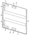
図3は、本発明の実施の形態1におけるケース上面板21の裏面側を見た斜視図である。図4は、本発明の実施の形態1におけるケース上面板21の表面側を見た斜視図である。図3に示すように、本実施形態では、6個の補強金具28がケース上面板21の裏面に配置されている。そして、図4に示すように、それらの補強金具28の各々に対して、個別に上部振れ止め金具27を固定することが可能である。このため、本実施形態では、複数の上部振れ止め金具27を用いて貯湯タンクユニット100と壁60とを連結することが可能であるので、貯湯タンクユニット100の耐震性能をより向上することができる。
FIG. 3 is a perspective view of the back surface side of the
また、本実施形態では、6個の補強金具28は、何れも同一の部品で構成されている。このため、部品の種類の増加を抑制することができ、コスト低減が図れる。
Moreover, in this embodiment, all the six
本実施形態における外郭ケース20は、ケース正面板23が開閉可能になっている。貯湯タンクユニット100の点検時等には、ケース正面板23を開くことにより、内蔵された機器の点検、修理、交換等を行うことができる。図3および図4に示すように、ケース上面板21の四辺のうち、ケース正面板23の上辺に並行して位置するケース上面板21の辺21aの近傍には補強金具28が配置されておらず、ケース背面板24の上辺に並行して位置するケース上面板21の辺21bの近傍には2個の補強金具28が配置され、ケース側面板25の上辺に並行して位置するケース上面板21の辺21cの近傍には2個の補強金具28が配置され、ケース側面板26の上辺に並行して位置するケース上面板21の辺21dの近傍には2個の補強金具28が配置されている。点検時等に開閉する可能性のあるケース正面板23を壁60に向けて貯湯タンクユニット100を設置することは通常は無いため、ケース正面板23の上辺に並行して位置するケース上面板21の辺21aの近傍に上部振れ止め金具27を固定することは通常は無い。このため、本実施形態のように、ケース正面板23の上辺に並行して位置するケース上面板21の辺21aの近傍を避けて補強金具28を配置することが合理的であり、利便性を損なうことなく、補強金具28の設置個数を抑制することができる。
In the
図4に示す例では、ケース上面板21の辺21bの近傍に配置された2個の補強金具28の位置に2個の上部振れ止め金具27がそれぞれ固定されている。図示を省略するが、ケース上面板21の辺21cの近傍に配置された2個の補強金具28の位置に2個の上部振れ止め金具27をそれぞれ固定することも可能であり、ケース上面板21の辺21dの近傍に配置された2個の補強金具28の位置に2個の上部振れ止め金具27をそれぞれ固定することも可能である。
In the example shown in FIG. 4, the two upper steady rests 27 are fixed to the positions of the two reinforcing
また、本実施形態では、複数の補強金具28のうちの一部は、ケース背面板24の上辺に並行して位置するケース上面板21の辺21bとケース側面板25の上辺に並行して位置するケース上面板21の辺21cとの角部の近傍と、ケース背面板24の上辺に並行して位置するケース上面板21の辺21bとケース側面板26の上辺に並行して位置するケース上面板21の辺21dとの角部の近傍とにそれぞれ配置されている。これらの角部は、外郭ケース20において直方体としての頂点の付近に位置するため、剛性が高い。このため、これらの角部に補強金具28を配置して上部振れ止め金具27を連結することにより、上部振れ止め金具27をより強固に貯湯タンクユニット100に連結することができ、耐震性をより向上することができる。
In the present embodiment, some of the plurality of reinforcing
図5は、本発明の実施の形態1の変形例におけるケース上面板21の裏面側を見た斜視図である。図5に示す変形例では、図3に示す例でケース上面板21の辺21bと辺21cとの角部の近傍に配置された2個の補強金具28に代えて、これらを一体化してL字型に形成した補強金具28Aを配置し、また、ケース上面板21の辺21bと辺21dとの角部の近傍に配置された2個の補強金具28に代えて、これらを一体化してL字型に形成した補強金具28Aを配置している。このような変形例の構成によれば、部品点数を削減することができ、コスト低減が図れる。
FIG. 5 is a perspective view of the back surface side of the case
図6は、本発明の実施の形態1の貯湯式給湯機の耐震構造を備えた貯湯タンクユニット100を上方から見た斜視図である。図6に示す例では、貯湯タンクユニット100の背面側と、一方の側面の側とに壁60がそれぞれ存在している。そして、ケース上面板21の辺21bの近傍に配置された2個の補強金具28の位置に2個の上部振れ止め金具27の一端がそれぞれ固定され、これらの上部振れ止め金具27の他端は、貯湯タンクユニット100の背面側にある壁60に対しボルト等の固定手段(図示せず)によりそれぞれ固定されている。また、ケース上面板21の辺21dの近傍に配置された2個の補強金具28のうちの1個の位置に上部振れ止め金具27の一端が固定され、この上部振れ止め金具27の他端は、貯湯タンクユニット100の側面の側にある壁60に対しボルト等の固定手段(図示せず)により固定されている。
FIG. 6 is a perspective view of hot water
このように、本実施形態では、複数の上部振れ止め金具27を同一の壁60に固定することもできるし、複数の上部振れ止め金具27を貯湯タンクユニット100に対して異なる方向に位置する複数の壁60にそれぞれ固定することもできる。このため、貯湯タンクユニット100の設置場所の状況に応じて、より優れた耐震性が得られるように複数の上部振れ止め金具27を適切な箇所に配置することができる。
Thus, in the present embodiment, the plurality of upper steady rests 27 can be fixed to the
実施の形態2.
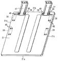
次に、図7および図8を参照して、本発明の実施の形態2について説明するが、上述した実施の形態1との相違点を中心に説明し、同一部分または相当部分は同一符号を付し説明を省略する。図7は、本発明の実施の形態2の貯湯式給湯機の耐震構造における補強金具28Bを示す斜視図である。図8は、本発明の実施の形態2における上部振れ止め金具27および補強金具28Bの付近を拡大して示す断面図である。
Embodiment 2. FIG.
Next, the second embodiment of the present invention will be described with reference to FIG. 7 and FIG. 8. The description will focus on the differences from the first embodiment described above, and the same or corresponding parts will be denoted by the same reference numerals. The description is omitted. FIG. 7 is a perspective view showing a reinforcing metal fitting 28B in the earthquake resistant structure of the hot water storage type water heater according to Embodiment 2 of the present invention. FIG. 8 is an enlarged sectional view showing the vicinity of the upper steady rest metal fitting 27 and the reinforcing metal fitting 28B in the second embodiment of the present invention.
図7に示すように、本実施の形態2における補強金具28Bには、下方に突出するリブ29が設けられている。図8に示すように、補強金具28Bのリブ29は、ケース背面板24の内面に重なって位置する。ケース上面板21の周縁部には、下方に突出するリブ21eが設けられている。ケース上面板21のリブ21eは、ケース背面板24の外側に重なっている。このようにして、補強金具28Bのリブ29と、ケース上面板21のリブ21eとが、ケース背面板24を挟んで重なって位置する。リブ29とケース背面板24とリブ21eとが重なった部分において、ケース背面板24およびリブ21eに形成された孔にネジ40が挿通され、このネジ40がリブ29に形成されたネジ孔に螺合され、ネジ40を締め付けることにより、リブ29とケース背面板24とリブ21eとが締結されている。
As shown in FIG. 7, the reinforcing metal fitting 28B according to the second embodiment is provided with a
このように、本実施の形態2では、補強金具28Bにリブ29を設けたことにより、補強金具28Bの剛性が向上し、上部振れ止め金具27と貯湯タンクユニット100とをより強固に連結することができる。また、リブ29がケース背面板24の近傍に配置されるので、リブ29が外郭ケース20の内部空間を狭めることがなく、収納される機器との干渉を防止することができる。また、本実施形態では、ケース上面板21とケース背面板24とを固定する固定手段(ネジ40)によってリブ29を共締めしていることにより、補強金具28Bを固定する固定手段の部品点数を削減することができる。また、補強金具28Bがリブ29を介してケース背面板24にも固定されるので、上部振れ止め金具27と貯湯タンクユニット100とをより強固に連結することができる。なお、図8では、リブ29がケース背面板24の近傍に配置される場合を例示したが、同様にして、リブ29をケース側面板25または26の近傍に配置し、ケース上面板21とケース側面板25または26とリブ29とをネジ40等の固定手段により共に固定しても良い。
As described above, in the second embodiment, the
10 貯湯タンク、20 外郭ケース、21 ケース上面板、
21a,21b,21c,21d 辺、21e リブ、22 ケース底面板、
23 ケース正面板、24 ケース背面板、25,26 ケース側面板、
27 上部振れ止め金具、28,28A,28B 補強金具、29 リブ、
30 脚構造、31 タンク下部脚、32 内部脚、33 据付脚、40 ネジ、
50 床面、60 壁、100 貯湯タンクユニット
10 hot water storage tanks, 20 outer case, 21 case top plate,
21a, 21b, 21c, 21d side, 21e rib, 22 case bottom plate,
23 Case front plate, 24 Case back plate, 25, 26 Case side plate,
27 Upper steady rest, 28, 28A, 28B Reinforcing bracket, 29 Rib,
30-leg structure, 31 tank lower leg, 32 internal leg, 33 installation leg, 40 screws,
50 floors, 60 walls, 100 hot water tank unit
Claims (6)
前記ケース上面板の裏面に配置され、前記貯湯タンクに接触しない複数の補強部材と、
前記ケース上面板と、外部の構造体とを連結する上部振れ止め部材と、
を備え、
前記上部振れ止め部材の一端は、前記ケース上面板と前記補強部材とに固定可能であり、前記上部振れ止め部材の他端は、前記構造体に固定可能であり、
前記外郭ケースは、正面を形成するケース正面板と、側面を形成するケース側面板と、背面を形成するケース背面板とを有し、前記ケース正面板は、点検時に開閉可能であり、
前記補強部材は、前記ケース正面板の上辺に並行して位置する前記ケース上面板の辺の近傍には配置されず、前記ケース背面板の上辺に並行して位置する前記ケース上面板の辺の近傍と、前記ケース側面板の上辺に並行して位置する前記ケース上面板の辺の近傍とに配置されている貯湯式給湯機の耐震構造。 A case upper surface plate that forms the upper surface of the outer case of the hot water storage tank unit containing the hot water storage tank;
A plurality of reinforcing members disposed on the back surface of the case top plate and not in contact with the hot water storage tank ;
An upper steadying member for connecting the case top plate and an external structure;
With
One end of the upper bracing member is securable to said reinforcing member and the case upper plate, the other end of the upper bracing member, Ri fixable der to said structure,
The outer case has a case front plate that forms the front, a case side plate that forms the side, and a case back plate that forms the back, and the case front plate can be opened and closed during inspection,
The reinforcing member is not arranged in the vicinity of the side of the case upper surface plate positioned in parallel with the upper side of the case front plate, and is provided on the side of the case upper surface plate positioned in parallel with the upper side of the case back plate. seismic neighborhood structure and the case upper surface plate of the side water storage type water heater that is disposed in the vicinity of that position in parallel to the upper side of the case side plates.
前記ケース上面板の裏面に配置され、前記貯湯タンクに接触しない複数の補強部材と、
前記ケース上面板と、外部の構造体とを連結する上部振れ止め部材と、
を備え、
前記上部振れ止め部材の一端は、前記ケース上面板と前記補強部材とに固定可能であり、前記上部振れ止め部材の他端は、前記構造体に固定可能であり、
前記外郭ケースは、正面を形成するケース正面板と、側面を形成するケース側面板と、背面を形成するケース背面板とを有し、
前記補強部材は、下方に突出するリブを有し、
前記ケース側面板と前記ケース背面板との一方または両方の近傍に前記リブが配置されている貯湯式給湯機の耐震構造。 A case upper surface plate that forms the upper surface of the outer case of the hot water storage tank unit containing the hot water storage tank;
A plurality of reinforcing members disposed on the back surface of the case top plate and not in contact with the hot water storage tank ;
An upper steadying member for connecting the case top plate and an external structure;
With
One end of the upper bracing member is securable to said reinforcing member and the case upper plate, the other end of the upper bracing member, Ri fixable der to said structure,
The outer case has a case front plate forming a front surface, a case side plate forming a side surface, and a case back plate forming a back surface,
The reinforcing member has a rib protruding downward,
Seismic structure of hot-water storage type water heater that has the ribs are disposed in the vicinity of one or both of the case rear plate and the casing side plates.
Priority Applications (1)
| Application Number | Priority Date | Filing Date | Title |
|---|---|---|---|
| JP2012162538A JP5874559B2 (en) | 2012-07-23 | 2012-07-23 | Seismic structure of hot water storage water heater |
Applications Claiming Priority (1)
| Application Number | Priority Date | Filing Date | Title |
|---|---|---|---|
| JP2012162538A JP5874559B2 (en) | 2012-07-23 | 2012-07-23 | Seismic structure of hot water storage water heater |
Publications (3)
| Publication Number | Publication Date |
|---|---|
| JP2014020745A JP2014020745A (en) | 2014-02-03 |
| JP2014020745A5 JP2014020745A5 (en) | 2015-03-12 |
| JP5874559B2 true JP5874559B2 (en) | 2016-03-02 |
Family
ID=50195828
Family Applications (1)
| Application Number | Title | Priority Date | Filing Date |
|---|---|---|---|
| JP2012162538A Active JP5874559B2 (en) | 2012-07-23 | 2012-07-23 | Seismic structure of hot water storage water heater |
Country Status (1)
| Country | Link |
|---|---|
| JP (1) | JP5874559B2 (en) |
Families Citing this family (1)
| Publication number | Priority date | Publication date | Assignee | Title |
|---|---|---|---|---|
| JP6386917B2 (en) * | 2015-01-06 | 2018-09-05 | リンナイ株式会社 | Hot water storage water heater |
Family Cites Families (7)
| Publication number | Priority date | Publication date | Assignee | Title |
|---|---|---|---|---|
| JPH0442680Y2 (en) * | 1988-01-21 | 1992-10-08 | ||
| JP3647096B2 (en) * | 1995-10-11 | 2005-05-11 | 株式会社キューヘン | Hot water storage type electric water heater |
| JPH09203563A (en) * | 1996-01-29 | 1997-08-05 | Toshiba Electric Appliance Co Ltd | Hot water heater |
| JPH1137559A (en) * | 1997-07-16 | 1999-02-12 | Sekisui Chem Co Ltd | Storage type water heater |
| JP2007151778A (en) * | 2005-12-05 | 2007-06-21 | Amakusa Toshio | Furniture falling prevention device |
| JP4821729B2 (en) * | 2007-07-26 | 2011-11-24 | パナソニック電工株式会社 | Storage furniture fixing structure |
| JP5133078B2 (en) * | 2008-01-23 | 2013-01-30 | パナソニック株式会社 | Hot water storage tank unit |
-
2012
- 2012-07-23 JP JP2012162538A patent/JP5874559B2/en active Active
Also Published As
| Publication number | Publication date |
|---|---|
| JP2014020745A (en) | 2014-02-03 |
Similar Documents
| Publication | Publication Date | Title |
|---|---|---|
| JP6128331B2 (en) | Hot water heater | |
| JP2009180489A (en) | Heat pump type water heater | |
| JP5874559B2 (en) | Seismic structure of hot water storage water heater | |
| JP5163159B2 (en) | Heat pump water heater | |
| JP2008032240A (en) | Heat pump type water heater | |
| JP2016156524A (en) | Storage water heater | |
| JP5316229B2 (en) | Hot water storage hot water unit | |
| JP6910051B2 (en) | Water heater | |
| JP2014214884A (en) | Hot water storage water heater and casing | |
| JP2013036697A (en) | Air conditioner outdoor unit | |
| JP4687522B2 (en) | Hot water storage tank unit | |
| JP5582335B2 (en) | Heat source machine | |
| JP4906763B2 (en) | Hot water storage water heater | |
| JP5807739B2 (en) | Case mounting structure | |
| JP5759258B2 (en) | Hot water storage tank unit | |
| JP7294203B2 (en) | Hot water storage type water heater and its installation method | |
| JP2010276229A (en) | Warm water type heating device | |
| JP5874422B2 (en) | Hot water storage water heater | |
| JP6420577B2 (en) | Hot water storage water heater | |
| JP6319052B2 (en) | Hot water storage water heater | |
| JP2016142435A (en) | Storage water heater | |
| JP6213206B2 (en) | Hot water storage water heater | |
| JP6124042B2 (en) | Waterproof pan for bathtub | |
| JP4167611B2 (en) | Through-wall combustor | |
| JP2005164136A (en) | Heat pump water heater |
Legal Events
| Date | Code | Title | Description |
|---|---|---|---|
| A621 | Written request for application examination |
Free format text: JAPANESE INTERMEDIATE CODE: A621 Effective date: 20150106 |
|
| A521 | Request for written amendment filed |
Free format text: JAPANESE INTERMEDIATE CODE: A523 Effective date: 20150126 |
|
| A977 | Report on retrieval |
Free format text: JAPANESE INTERMEDIATE CODE: A971007 Effective date: 20151009 |
|
| A131 | Notification of reasons for refusal |
Free format text: JAPANESE INTERMEDIATE CODE: A131 Effective date: 20151110 |
|
| A521 | Request for written amendment filed |
Free format text: JAPANESE INTERMEDIATE CODE: A523 Effective date: 20151202 |
|
| TRDD | Decision of grant or rejection written | ||
| A01 | Written decision to grant a patent or to grant a registration (utility model) |
Free format text: JAPANESE INTERMEDIATE CODE: A01 Effective date: 20151222 |
|
| A61 | First payment of annual fees (during grant procedure) |
Free format text: JAPANESE INTERMEDIATE CODE: A61 Effective date: 20160104 |
|
| R150 | Certificate of patent or registration of utility model |
Ref document number: 5874559 Country of ref document: JP Free format text: JAPANESE INTERMEDIATE CODE: R150 |
|
| R250 | Receipt of annual fees |
Free format text: JAPANESE INTERMEDIATE CODE: R250 |
|
| R250 | Receipt of annual fees |
Free format text: JAPANESE INTERMEDIATE CODE: R250 |
|
| R250 | Receipt of annual fees |
Free format text: JAPANESE INTERMEDIATE CODE: R250 |
|
| R250 | Receipt of annual fees |
Free format text: JAPANESE INTERMEDIATE CODE: R250 |
|
| R250 | Receipt of annual fees |
Free format text: JAPANESE INTERMEDIATE CODE: R250 |
|
| R250 | Receipt of annual fees |
Free format text: JAPANESE INTERMEDIATE CODE: R250 |