JP2012241316A - Corner eaves - Google Patents

Corner eaves Download PDF

Info

Publication number
JP2012241316A
JP2012241316A JP2011108919A JP2011108919A JP2012241316A JP 2012241316 A JP2012241316 A JP 2012241316A JP 2011108919 A JP2011108919 A JP 2011108919A JP 2011108919 A JP2011108919 A JP 2011108919A JP 2012241316 A JP2012241316 A JP 2012241316A
Authority
JP
Japan
Prior art keywords
corner
wall
arm member
fixed
ridge
Prior art date
Legal status (The legal status is an assumption and is not a legal conclusion. Google has not performed a legal analysis and makes no representation as to the accuracy of the status listed.)
Withdrawn
Application number
JP2011108919A
Other languages
Japanese (ja)
Inventor
Junji Kitagawa
淳二 北川
Yoshitaka Watanabe
義孝 渡辺
Current Assignee (The listed assignees may be inaccurate. Google has not performed a legal analysis and makes no representation or warranty as to the accuracy of the list.)
Daiken Co Ltd
Original Assignee
Daiken Co Ltd
Priority date (The priority date is an assumption and is not a legal conclusion. Google has not performed a legal analysis and makes no representation as to the accuracy of the date listed.)
Filing date
Publication date
Application filed by Daiken Co Ltd filed Critical Daiken Co Ltd
Priority to JP2011108919A priority Critical patent/JP2012241316A/en
Publication of JP2012241316A publication Critical patent/JP2012241316A/en
Withdrawn legal-status Critical Current

Links

Images

Abstract

PROBLEM TO BE SOLVED: To provide corner eaves formed by connecting a plurality of eaves members extending toward the outdoor.SOLUTION: Outside corner eaves 1 of an outside corner part 4 connected to outer wall eaves 6 for which a plurality of intermediate materials 24 that are eaves members projected from the outer wall 3 of a building to the outdoor are connected along the outer wall comprise: an attaching member 2 fixed to the outside corner part 4; an arm member 5 supported by the attaching member 2 at one end and extending in an outdoor direction along a bisector bisecting an angle formed by the outside corner part 4; and a corner eaves panel 8 installed between an outside corner side end 7 of the outer wall eaves 6 and the arm member 5. For the corner eaves panel 8, a first end face along the arm member 5 is fixed to the arm member 5, and a front edge part 21 which is a second end face along an outdoor side end face of the outer wall eaves 6 is fixed to a distal end parting material 22 which is a connecting member for connecting outdoor side end faces of the intermediate materials 24.

Description

本発明は、屋外に向かって伸延する庇部材を外壁に沿って複数個連結して形成した庇を外壁の出隅または入隅で連結するコーナー庇構造に関する。   The present invention relates to a corner ridge structure in which a ridge formed by connecting a plurality of ridge members extending toward the outdoors along an outer wall is connected at an outer corner or an inner corner of the outer wall.

建物の一方の外壁に設置した庇と他方の外壁に設置した庇とを、外壁の出隅または入隅で連結したい場合がある。特許文献1には、外壁の出隅に設置されるコーナー庇が記載されている。一方の壁面に設置される庇と他方の壁面に設置される庇とは、夫々外壁の出隅に位置する端部がトメ切りされており、2つの庇は、出隅の端部がコーナーブロックを介してトメ接合される。   There is a case where it is desired to connect a fence installed on one outer wall of a building and a fence installed on the other outer wall at an outer corner or an inner corner of the outer wall. Patent Document 1 describes a corner ridge installed at a protruding corner of an outer wall. The heels installed on one wall surface and the heels installed on the other wall surface are cut off at the ends located at the outer corners of the outer wall. To be joined.

特開2009−68269号公報JP 2009-68269 A

特許文献1に記載されるコーナー庇では、壁面部の庇が壁面に沿って出隅に伸延した状態で、コーナー庇と壁面部の庇とが一体成型されているので、出隅の庇の荷重は壁面部の庇を支持する支持部材によって受けることができる。ところが、一体成型の庇では庇の出幅を任意に選択することができず、さらに運搬コストが嵩む。そこで屋外に向かって伸延する庇部材を複数個外壁に沿って連結して庇を形成したい場合がある。このような場合に、コーナー庇も庇部材を横方向に連結して形成することができれば庇全体を統一した外観とすることができ、運搬する上でも便利であるが、この場合にコーナー庇をどのように支持するかという問題がある。出隅のコーナー庇について説明してきたが、入隅のコーナー庇についても同様の問題がある。   In the corner ridge described in Patent Document 1, the corner ridge and the wall surface ridge are integrally formed with the wall surface ridge extending along the wall surface to the exit corner. Can be received by a support member that supports the ridges of the wall surface. However, in the case of an integrally molded ridge, the protruding width of the ridge cannot be selected arbitrarily, and the transportation cost increases. Therefore, there is a case where a plurality of eaves members extending outward are connected along the outer wall to form eaves. In such a case, if the corner ridge can also be formed by connecting the heel members in the lateral direction, the entire heel can be made uniform in appearance, which is convenient for transportation. There is a problem of how to support it. Although the corner corner の has been described, there is a similar problem with the corner corner 入.

本発明の目的は、このような課題を解決するもので、屋外に向かって伸延する庇部材を複数個連結して形成されるコーナー庇を提供することである。   An object of the present invention is to solve such a problem and to provide a corner ridge formed by connecting a plurality of heel members extending outward.

この課題を解決するために請求項1の発明は、建物の外壁から屋外に向かって張り出す庇部材が外壁に沿って複数個連結された外壁庇に連設される出隅の出隅コーナー庇であって、出隅に固定される取り付け部材と、取り付け部材に一端部が支持され、出隅が成す角を2等分する2等分線に沿って屋外方向に伸延するアーム部材と、外壁庇の出隅側端部とアーム部材との間に設置されるコーナー庇パネルとを備え、コーナー庇パネルは、アーム部材に沿う第1の端面がアーム部材に固定され、外壁庇の出隅側端部に沿う第2の端面が出隅側端部に固定され、第3の端面である屋外側の端面が、外壁庇を形成する複数個の庇部材の屋外側端面を連結する連結部材に固定されるものである。   In order to solve this problem, according to the first aspect of the present invention, there is provided a protruding corner corner ridge in which a plurality of ridge members projecting outward from the outer wall of the building are connected to the outer wall ridge connected along the outer wall. And a mounting member fixed to the projecting corner, an arm member having one end supported by the mounting member, and extending in the outdoor direction along a bisector that bisects the angle formed by the projecting corner, and an outer wall A corner heel panel installed between an end portion of the heel corner and the arm member, and the corner heel panel has a first end surface along the arm member fixed to the arm member, and a corner side of the outer wall heel. The second end face along the end is fixed to the end corner side end, and the outdoor end face as the third end face is a connecting member that connects the outdoor end faces of the plurality of eaves members forming the outer wall eaves. It is fixed.

請求項2の発明では、アーム部材は固定用ステーによって出隅を構成する外壁に固定され、アーム部材の一端部には水平方向に臨み互いに対向する取り付け面が設けられ、取り付け部材には、取り付け面に当接してアーム部材を水平方向にねじ止めする当接面と、取り付け部材を出隅を構成する外壁に固定する固定部とが設けられているものである。   In the invention of claim 2, the arm member is fixed to the outer wall constituting the protruding corner by the fixing stay, and the arm member is provided with a mounting surface facing the horizontal direction at one end of the arm member. An abutting surface for abutting the surface and screwing the arm member in the horizontal direction and a fixing portion for fixing the mounting member to the outer wall constituting the protruding corner are provided.

請求項3の発明は、建物の外壁から屋外に向かって張り出す庇部材が外壁に沿って複数個連結された外壁庇に連設される入隅の入隅コーナー庇であって、入隅に固定される取り付け部が設けられ、入隅が成す角を2等分する2等分線に沿って屋外方向に伸延するアーム部材と、外壁庇の入隅側端部とアーム部材との間に設置されるコーナー庇パネルとを備え、コーナー庇パネルは、アーム部材に沿う第1の端面がアーム部材に固定され、外壁庇の入隅側端部に沿う第2の端面が入隅側端部に固定され、第3の端面である外壁側の端面が、外壁庇を形成する複数個の庇部材の外壁側端面を支持する支持部材に固定されるものである。   The invention according to claim 3 is a corner corner ridge of a corner in which a plurality of ridge members projecting outward from the outer wall of the building are connected to the outer wall ridge connected along the outer wall. A fixed attachment portion is provided, and extends between the arm member extending in the outdoor direction along a bisector that bisects the angle formed by the corner, and between the corner portion end of the outer wall wall and the arm member. The corner wall panel is provided with a first end surface along the arm member fixed to the arm member, and a second end surface along the inner corner side end of the outer wall wall is the inner corner side end. The end surface on the outer wall side, which is the third end surface, is fixed to a support member that supports the outer wall side end surfaces of the plurality of scissors members forming the outer wall scissors.

請求項4の発明において、コーナー庇パネルは第2の端面の周縁部が固定用ステーによって入隅を構成する外壁に固定されるものである。   According to a fourth aspect of the present invention, the corner wall panel is fixed to the outer wall of which the peripheral edge portion of the second end face constitutes the entrance corner by the fixing stay.

屋外に向かって伸延する庇部材を複数個連結して形成されるコーナー庇を提供することができる。   A corner ridge formed by connecting a plurality of heel members extending toward the outdoors can be provided.

第1の実施の形態に係る出隅コーナー庇の平面図である。It is a top view of the protruding corner corner ridge according to the first embodiment. 取り付け部材の詳細図である。It is detail drawing of an attachment member. アーム部材の縦断面図である。It is a longitudinal cross-sectional view of an arm member. アーム部材の横断面図である。It is a cross-sectional view of an arm member. 第2の実施の形態に係る入隅コーナー庇の平面図である。It is a top view of the corner corner ridge which concerns on 2nd Embodiment. 補強材の平面図である。It is a top view of a reinforcing material. 補強材の正面図である。It is a front view of a reinforcing material.

以下、本発明の第1の実施の形態について図1〜図4に基づいて説明する。
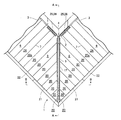
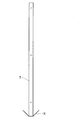
出隅コーナー庇1は、出隅4に固定される取り付け部材2と、取り付け部材2に一端部が支持され、2つの外壁3で形成される出隅4が成す角を2等分する2等分線に沿って屋外方向に伸延するアーム部材5と、外壁庇6の出隅側端部7とアーム部材5との間に設置されるコーナー庇パネル8とを備える。
Hereinafter, a first embodiment of the present invention will be described with reference to FIGS.
The exit corner corner 庇 1 has an attachment member 2 fixed to the exit corner 4, one end portion supported by the attachment member 2, and the like, which bisects the angle formed by the exit corner 4 formed by the two outer walls 3. An arm member 5 extending in the outdoor direction along the dividing line, and a corner heel panel 8 installed between the protruding corner side end 7 of the outer wall ridge 6 and the arm member 5 are provided.

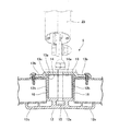
取り付け部材2は、一対の第1部材9と第2部材10とをからなる。第1部材9と第2部材10とは、ともに金属製の平板をくの字状に折り曲げられ左右対称に形成される。第1部材9と第2部材10とは、出隅4を構成する各々の外壁3に固定される板部9a,10aと、アーム部材5の取り付け面11に当接してアーム部材5をねじ止めする板部9b,10bとを備える。板部9a,10aはアンカーボルトを用いて外壁に固定される。   The attachment member 2 includes a pair of a first member 9 and a second member 10. Both the first member 9 and the second member 10 are formed symmetrically by bending a metal flat plate into a U-shape. The first member 9 and the second member 10 are abutted against the plate portions 9a and 10a fixed to the respective outer walls 3 constituting the protruding corner 4 and the mounting surface 11 of the arm member 5 and screwed the arm member 5 Plate portions 9b and 10b. The plate portions 9a and 10a are fixed to the outer wall using anchor bolts.

アーム部材5は、下部ジョイント材12と上部ジョイント材13と補強材14とを備える。下部ジョイント材12と上部ジョイント材13とはアルミ押出し型材を用いて形成され、補強材14はステンレス板を曲げ加工して形成される。
下部ジョイント材12は開口部が上方に臨んだ断面コの字状であり、底板部12aの両端には両側板12bの外側に伸延した板部12cが形成された長尺物である。底板部12aの中央上面側には長手方向に、あり溝15が形成されており、上部ジョイント材13をボルト止めするボルト頭部がこのあり溝に嵌め込まれる。補強材14は、断面がコの字状の長尺物であり、開口部を下向きにして底板14aが上方に位置した状態で、下部ジョイント材12の開口部に収容される。
The arm member 5 includes a lower joint material 12, an upper joint material 13, and a reinforcing material 14. The lower joint material 12 and the upper joint material 13 are formed using an aluminum extrusion mold material, and the reinforcing material 14 is formed by bending a stainless steel plate.
The lower joint material 12 has a U-shaped cross section with an opening facing upward, and is a long object in which plate portions 12c extending outward from both side plates 12b are formed at both ends of the bottom plate portion 12a. A dovetail groove 15 is formed in the longitudinal direction on the center upper surface side of the bottom plate portion 12a, and a bolt head for bolting the upper joint material 13 is fitted into the dovetail groove. The reinforcing member 14 is a long object having a U-shaped cross section, and is accommodated in the opening of the lower joint member 12 with the opening facing downward and the bottom plate 14a positioned upward.

上部ジョイント材13は、中央部に上方に凸となる段付き部13aが長手方向に沿って形成され、段付き部13aの両側に板部13bが形成された板状の長尺物である。上部ジョイント材13は、段付き部13aの底面13cが補強材14の底板14a上面に当接した状態で、下部ジョイント材12にボルト止めされる。このとき、上部ジョイント材13には段付き部13aが形成されているので、上部ジョイント材13と下部ジョイント材12との位置決めを容易に行うことができる。   The upper joint material 13 is a plate-like long object in which a stepped portion 13a that protrudes upward in the center is formed along the longitudinal direction, and plate portions 13b are formed on both sides of the stepped portion 13a. The upper joint material 13 is bolted to the lower joint material 12 in a state where the bottom surface 13c of the stepped portion 13a is in contact with the upper surface of the bottom plate 14a of the reinforcing material 14. At this time, since the stepped portion 13a is formed in the upper joint material 13, the upper joint material 13 and the lower joint material 12 can be easily positioned.

補強材14は、上部ジョイント材13および下部ジョイント材12から長手方向基端部側に突出した突出部14bを備えている。この突出部14bが取り付け部材2にボルト止めされる。さらに、上部ジョイント材13の板部13bには、長手方向に沿ってコーナー庇パネル8をねじ止めするためのねじ孔17が複数個所設けられている。   The reinforcing member 14 includes a protruding portion 14 b that protrudes from the upper joint material 13 and the lower joint material 12 toward the base end side in the longitudinal direction. This protrusion 14b is bolted to the attachment member 2. Further, the plate portion 13b of the upper joint member 13 is provided with a plurality of screw holes 17 for screwing the corner ridge panel 8 along the longitudinal direction.

アーム部材5は、取り付け部材2を構成する第1部材9と第2部材10との板部9b,10bによって補強材14突出部14bの取り付け面11が挟み込まれた状態で水平方向にボルト止めされる。第1部材9と第2部材10との板部9b,10bは、曲げ剛性を向上させるために上下方向の幅が幅広に形成されている。なお、第1部材9と第2部材10との板部9b,10bに形成されたボルト取り付け孔18は、アーム部材5の取り付け位置を調整可能とするために、庇の張り出し方向に細長な長孔とされる。   The arm member 5 is bolted in the horizontal direction in a state where the mounting surface 11 of the reinforcing member 14 protruding portion 14b is sandwiched between the plate portions 9b and 10b of the first member 9 and the second member 10 constituting the mounting member 2. The The plate portions 9b, 10b of the first member 9 and the second member 10 are formed with a wide vertical width in order to improve bending rigidity. The bolt mounting holes 18 formed in the plate portions 9b, 10b of the first member 9 and the second member 10 are long and narrow in the overhanging direction of the arm so that the mounting position of the arm member 5 can be adjusted. It is a hole.

コーナー庇パネル8は、コーナー中間材20が複数個連結されて形成される。コーナー中間材20同士は、接合部にピンが嵌合された状態で連結される。アーム部材5に長手方向に沿って当接するコーナー庇パネル8の端面は、下部ジョイント材12の側板12bおよび板部12cと、上部ジョイント材13の板部13bとによって形成される凹部16に嵌め込まれた状態で上部ジョイント材13にねじ止めされる。コーナー庇パネル8の前縁部21には不図示の先端ブラケットがビス止めされ、この先端ブラケットに先端見切り材22が装着される。コーナー庇パネル8は、外壁3に沿って取り付けられる外壁庇6に隣接して設置されるが、この外壁庇6に装着される先端見切り材22は出隅側に張り出した状態で設置される。出隅側に張り出した先端見切り材22の張り出し部がコーナー庇パネル8の先端ブラケットに固定される。先端見切り材22同士は、出隅角部において、シール処理された状態で当接し、あるいは溶接され、または接着された状態で当接する。   The corner saddle panel 8 is formed by connecting a plurality of corner intermediate members 20. The corner intermediate members 20 are connected to each other with a pin fitted to the joint. The end surface of the corner heel panel 8 that contacts the arm member 5 along the longitudinal direction is fitted into a recess 16 formed by the side plate 12b and the plate portion 12c of the lower joint material 12 and the plate portion 13b of the upper joint material 13. In this state, it is screwed to the upper joint material 13. A front end bracket (not shown) is screwed to the front edge portion 21 of the corner ridge panel 8, and a front end parting member 22 is attached to the front end bracket. The corner wall panel 8 is installed adjacent to the outer wall wall 6 attached along the outer wall 3, and the tip parting material 22 attached to the outer wall wall 6 is installed in a state of projecting to the protruding corner side. The projecting portion of the tip parting material 22 projecting to the projecting corner side is fixed to the tip bracket of the corner ridge panel 8. The tip parting materials 22 are in contact with each other in a sealed state, or are in contact with each other in a state where they are welded or bonded at the corners.

ここで出隅コーナー庇1の組み立て手順について説明する。取り付け部材2を構成する第1部材9と第2部材10とが出隅4を構成する各々の外壁3に固定される。第1部材9と第2部材10とは、板部9a,10aがアンカーボルトを用いて固定される。第1部材9と第2部材10との板部9b,10bには、アーム部材5が連結される。アーム部材5は、補強材14突出部14bの取り付け面11が第1部材9と第2部材10との板部9b,10bに挟み込まれた状態で水平方向にボルト止めされる。なお、アーム部材5には、固定用ステー23が取り付けられる。固定用ステー23の他端部は出隅部外壁3に支持される。   Here, a procedure for assembling the protruding corner 1 is described. A first member 9 and a second member 10 constituting the attachment member 2 are fixed to each outer wall 3 constituting the protruding corner 4. The plate member 9a, 10a is fixed to the first member 9 and the second member 10 using anchor bolts. The arm member 5 is coupled to the plate portions 9 b and 10 b of the first member 9 and the second member 10. The arm member 5 is bolted in the horizontal direction in a state where the attachment surface 11 of the protruding portion 14b of the reinforcing member 14 is sandwiched between the plate portions 9b and 10b of the first member 9 and the second member 10. A fixing stay 23 is attached to the arm member 5. The other end of the fixing stay 23 is supported by the outer corner outer wall 3.

固定用ステー23で支持されたアーム部材5には、コーナー庇パネル8が取り付けられる。コーナー庇パネル8は、コーナー中間材20の接合部にピンが嵌合され、あるいはコーナー中間材20の接合部がビス止めされてコーナー中間材20が複数個連結されて形成される。コーナー庇パネル8のアーム部材5に沿う第1の端面が、アーム部材5の長手方向に沿って形成された凹部16に嵌め込まれ、上部ジョイント材13の板部13bにねじ止めされる。   A corner rod panel 8 is attached to the arm member 5 supported by the fixing stay 23. The corner saddle panel 8 is formed by fitting a pin to a joint portion of the corner intermediate member 20 or by connecting a plurality of corner intermediate members 20 by screwing the joint portion of the corner intermediate member 20. A first end face along the arm member 5 of the corner rod panel 8 is fitted into a recess 16 formed along the longitudinal direction of the arm member 5 and is screwed to the plate portion 13 b of the upper joint material 13.

アーム部材5に取り付けられたコーナー庇パネル8の外壁庇6出隅側端部7に沿う第2の端面と、外壁3に沿って取り付けられた外壁庇6の出隅側端部7とは、コーナー庇パネル8の端部に位置するコーナー中間材20aと、外壁庇6の端部に位置する中間材24との接合部にピンが嵌合され、あるいはビス止めされて連結され固定される。コーナー中間材20aの基端部は、隣接する中間材24と同様に連結部材である壁取り付け材25とパネル取り付け材26とによって支持される。コーナー庇パネル8の第3の端面である前縁部には先端ブラケット27がビス止めされる。外壁庇6に装着された連結部材である先端見切り材22は出隅コーナー庇1側に張り出した状態で設置されており、この先端見切り材22の張り出し部が先端ブラケット27に固定される。先端見切り材22同士は出隅角部においてシール処理された状態で当接し、あるいは溶接され、または接着された状態で当接する。コーナー庇パネル8の基端部側には、取り付け部材2を覆うように上部カバー材28aと下部カバー材28bが取り付けられる。   The second end surface of the corner wall panel 8 attached to the arm member 5 along the outer wall edge 6 of the outer wall wall 6 and the outer edge 3 of the outer wall wall 6 attached along the outer wall 3 are: A pin is fitted to the joint between the corner intermediate member 20a located at the end of the corner wall panel 8 and the intermediate member 24 located at the end of the outer wall wall 6, or is connected and fixed by screwing. The base end portion of the corner intermediate member 20a is supported by the wall attachment member 25 and the panel attachment member 26, which are connecting members, like the adjacent intermediate member 24. A front end bracket 27 is screwed to the front edge which is the third end face of the corner ridge panel 8. The tip parting material 22, which is a connecting member attached to the outer wall rod 6, is installed in a state of projecting toward the protruding corner corner 庇 1, and the projecting part of the tip parting material 22 is fixed to the tip bracket 27. The end parting materials 22 abut on each other at a projected corner portion in a sealed state, or abutted in a welded or bonded state. An upper cover material 28 a and a lower cover material 28 b are attached to the base end portion side of the corner ridge panel 8 so as to cover the attachment member 2.

以下、本発明の第2の実施の形態について図5〜図7に基づいて説明する。本実施の形態では入隅コーナー庇31について説明するが、第1の実施の形態の説明と重複する部分については説明を省略し、同一の参照符を用いる。   Hereinafter, a second embodiment of the present invention will be described with reference to FIGS. In the present embodiment, the corner corner ridge 31 will be described. However, the description overlapping with the description of the first embodiment is omitted, and the same reference numerals are used.

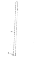
アーム部材32は、入隅33が成す角を2等分する2等分線に沿って屋外方向に伸延する。アーム部材32を入隅33の外壁34に固定する取り付け部35は、アーム部材32と一体に形成される。取り付け部35は、たとえば板材を用いて補強材14の長手方向一端部に溶接され、入隅33を構成する外壁34に当接した状態でねじ止めされる。取り付け部35は、曲げ剛性を向上させるために上下方向の幅が幅広に形成されている。   The arm member 32 extends in the outdoor direction along a bisector that bisects the angle formed by the entering corner 33. A mounting portion 35 for fixing the arm member 32 to the outer wall 34 of the entrance corner 33 is formed integrally with the arm member 32. The attachment portion 35 is welded to one end portion in the longitudinal direction of the reinforcing member 14 using, for example, a plate material, and is screwed in a state where the attachment portion 35 is in contact with the outer wall 34 constituting the entrance corner 33. The attachment portion 35 is formed with a wide vertical width in order to improve bending rigidity.

コーナー庇パネル36は、アーム部材32に沿う第1の端面がアーム部材32に固定され、外壁庇37の入隅側端部40に沿う第2の端面が入隅側端部40に固定される。第3の端面である外壁34側の端面は、外壁庇37を形成する複数個の庇部材である中間材38の外壁側端面を支持する、支持部材である壁取り付け材25とパネル取り付け材26とに固定される。コーナー庇パネル36の第2の端面の周縁部には、固定用ステーが取り付けられ、コーナー庇パネル36が入隅を構成する外壁に固定される。なお、先端見切り材39同士は入隅角部においてシール処理された状態で当接し、あるいは溶接され、または接着された状態で当接する。   The corner heel panel 36 has a first end face along the arm member 32 fixed to the arm member 32, and a second end face along the entry corner side end 40 of the outer wall ridge 37 is fixed to the entry corner side end 40. . The end face on the outer wall 34 side, which is the third end face, supports the wall attaching material 25 and the panel attaching material 26 which are support members that support the outer wall side end face of the intermediate member 38 which is a plurality of flange members forming the outer wall flange 37. And fixed to. A fixing stay is attached to the peripheral edge portion of the second end face of the corner heel panel 36, and the corner heel panel 36 is fixed to the outer wall constituting the entrance corner. It should be noted that the tip parting members 39 are in contact with each other in a sealed state at the corners, or in contact with each other in a welded or bonded state.

このように、建物の外壁3から屋外に向かって張り出す庇部材である中間材24が外壁3に沿って複数個連結された外壁庇6に連設される出隅4の出隅コーナー庇1であって、出隅4に固定される取り付け部材2と、取り付け部材2に一端部が支持され、出隅4が成す角を2等分する2等分線に沿って屋外方向に伸延するアーム部材5と、外壁庇6の出隅側端部7とアーム部材5との間に設置されるコーナー庇パネル8とを備え、コーナー庇パネル8は、アーム部材5に沿う第1の端面がアーム部材5に固定され、外壁庇6の出隅側端部7に沿う第2の端面が出隅側端部7に固定され、第3の端面である前縁部21が、外壁庇6を形成する複数個の庇部材である中間材24の屋外側端面を連結する連結部材である先端見切り材22に固定されるので、屋外に向かって伸延する庇部材であるコーナー中間材20を複数個連結して出隅コーナー庇1を形成することができる。   In this way, the protruding corner corner 庇 1 of the protruding corner 4 connected to the outer wall 庇 6 in which a plurality of intermediate members 24, which are ridge members that project outward from the outer wall 3 of the building, are connected along the outer wall 3. And an arm that extends in the outdoor direction along a bisector that bisects the angle formed by the projecting corner 4, with one end supported by the mounting member 2. A member 5 and a corner wall panel 8 installed between the end 7 of the outer wall wall 6 and the arm member 5. The corner wall panel 8 has an arm whose first end surface along the arm member 5 is an arm. The second end face that is fixed to the member 5 and that extends along the protruding corner side end 7 of the outer wall ridge 6 is fixed to the protruding corner end 7, and the front edge 21 that is the third end surface forms the outer wall ridge 6. Fixed to the end parting member 22 which is a connecting member for connecting the outdoor side end surfaces of the intermediate member 24 which is a plurality of eaves members. Since, it is possible to form the external corner corner eaves 1 corner intermediate member 20 is a canopy member which extends towards the outside with a plurality linked.

さらに、アーム部材5は固定用ステー23によって出隅4を構成する外壁3に固定され、アーム部材5の一端部には、水平方向に臨み互いに対向する取り付け面11が設けられ、取り付け部材2には、取り付け面に当接してアーム部材5を水平方向にねじ止めする当接面である板部9b,10bと、取り付け部材2を出隅4を構成する外壁3に固定する固定部である板部9a,10aとが設けられているので、アーム部材5の一端部が出隅4に支持される支持部である取り付け部材2の強度を向上させることができる。   Further, the arm member 5 is fixed to the outer wall 3 constituting the exit corner 4 by a fixing stay 23, and one end portion of the arm member 5 is provided with a mounting surface 11 facing in the horizontal direction and facing each other. Is a plate portion 9b, 10b that is a contact surface that contacts the mounting surface and screws the arm member 5 in the horizontal direction, and a plate that is a fixing portion that fixes the mounting member 2 to the outer wall 3 constituting the protruding corner 4. Since the portions 9a and 10a are provided, it is possible to improve the strength of the mounting member 2 which is a support portion in which one end portion of the arm member 5 is supported by the protruding corner 4.

さらに、建物の外壁34から屋外に向かって張り出す庇部材である中間材38が外壁34に沿って複数個連結された外壁庇37に連設される入隅33の入隅コーナー庇31であって、入隅33に固定される取り付け部35が設けられ入隅33が成す角を2等分する2等分線に沿って屋外方向に伸延するアーム部材32と、外壁庇37の入隅側端部40とアーム部材32との間に設置されるコーナー庇パネル36とを備え、コーナー庇パネル36は、アーム部材32に沿う第1の端面がアーム部材32に固定され、外壁庇37の入隅側端部40に沿う第2の端面が入隅側端部40に固定され、第3の端面である外壁34側の端面が、外壁庇37を形成する複数個の庇部材である中間材38の外壁側端面を支持する支持部材である壁取り付け材25とパネル取り付け材26とに固定されるので、屋外に向かって伸延する庇部材であるコーナー中間材38を複数個連結して入隅コーナー庇31を形成することができる。   Further, the corner member 31 is a corner member 31 of the corner 33 connected to a plurality of outer wall members 37, which are a plurality of intermediate members 38 extending outward from the outer wall 34 of the building. And an arm member 32 extending in the outdoor direction along a bisector that bisects the angle formed by the entrance corner 33, and an entrance corner side of the outer wall wall 37. The corner wall panel 36 is provided between the end 40 and the arm member 32, and the corner wall panel 36 has a first end surface along the arm member 32 fixed to the arm member 32, and the outer wall wall 37 is inserted. An intermediate material in which the second end surface along the corner side end portion 40 is fixed to the entrance corner side end portion 40, and the end surface on the outer wall 34 side which is the third end surface is a plurality of eaves members forming the outer wall eaves 37. Wall mounting material 2 which is a support member for supporting the outer wall side end face of 38 And because it is secured to the panel mounting member 26 can be a corner intermediate material 38 is a canopy member which extends towards the outside with a plurality linked to form an incoming corner corner eaves 31.

さらに、コーナー庇パネル36は第2の端面の周縁部が固定用ステー23によって入隅33を構成する外壁34に固定されるので、入隅コーナー庇の強度を控除させることができる。   Further, since the peripheral edge portion of the second end surface of the corner heel panel 36 is fixed to the outer wall 34 constituting the entrance corner 33 by the fixing stay 23, the strength of the entrance corner corner ridge can be deducted.

1 出隅コーナー庇
2 取り付け部材
3,34 外壁
4 出隅
5,32 アーム部材
6,37 外壁庇
7 出隅側端部
8,36 コーナー庇パネル
9 第1部材
9a,9b,10a,10b,12c,13b 板部
10 第2部材
11 取り付け面
12 下部ジョイント材
12a 底板部
12b 側板
13 上部ジョイント材
13a 段付き部
13c 底面
14 補強材
14a 底板
14b 突出部
15 あり溝
16 凹部
17 ねじ孔
18 ボルト取り付け孔
20 コーナー中間材
21 前縁部
22,39 先端見切り材
23 固定用ステー
24,38 中間材
25 壁取り付け材
26 パネル取り付け材
27 先端ブラケット
28a 上部カバー材
28b 下部カバー材
31 入隅コーナー庇
33 入隅
35 取り付け部
40 入隅側端部
1 Out corner corner
2 Mounting member 3,34 Outer wall 4 Outer corner 5,32 Arm member 6,37 Outer wall rod 7 Outer corner side end 8,36 Corner rod panel 9 First member 9a, 9b, 10a, 10b, 12c, 13b Plate portion 10 Second member 11 Mounting surface 12 Lower joint material 12a Bottom plate portion 12b Side plate 13 Upper joint material 13a Stepped portion 13c Bottom surface 14 Reinforcement material 14a Bottom plate 14b Protruding portion 15 Dovetail groove 16 Recessed portion 17 Screw hole 18 Bolt mounting hole 20 Corner intermediate material 21 Front edge 22, 39 End parting material 23 Fixing stay 24, 38 Intermediate material 25 Wall mounting material 26 Panel mounting material 27 End bracket 28a Upper cover material 28b Lower cover material 31 Corner corner ridge 33 Corner 35 Mounting portion 40 Corner edge

Claims (4)

建物の外壁から屋外に向かって張り出す庇部材が外壁に沿って複数個連結された外壁庇に連設される出隅部分の出隅コーナー庇であって、
出隅部分に固定される取り付け部材と、
取り付け部材に一端部が支持され、出隅部分が成す角を2等分する2等分線に沿って屋外方向に伸延するアーム部材と、
外壁庇の出隅側端部とアーム部材との間に設置されるコーナー庇パネルとを備え、
コーナー庇パネルは、アーム部材に沿う第1の端面がアーム部材に固定され、外壁庇の出隅側端部に沿う第2の端面が出隅側端部に固定され、第3の端面である屋外側の端面が、外壁庇を形成する複数個の庇部材の屋外側端面を連結する連結部材に固定されることを特徴とする出隅コーナー庇。
A projecting corner section of the projecting corner portion that is connected to the plurality of outer wall casings that are connected along the outer wall from the outer wall of the building.
An attachment member fixed to the protruding corner portion;
An arm member supported at one end by the mounting member and extending in the outdoor direction along a bisector that bisects the angle formed by the protruding corner portion;
A corner wall panel installed between the end of the outer wall wall and the arm member;
The corner wall panel has a first end surface along the arm member fixed to the arm member, and a second end surface along the protruding corner side end portion of the outer wall wall fixed to the protruding corner side end portion, which is a third end surface. An exterior corner ridge, wherein an end face on the outdoor side is fixed to a connecting member for connecting outdoor end faces of a plurality of ridge members forming the outer wall ridge.
アーム部材は固定用ステーによって出隅を構成する外壁に固定され、
アーム部材の一端部には水平方向に臨み互いに対向する取り付け面が設けられ、
取り付け部材には、取り付け面に当接してアーム部材を水平方向にねじ止めする当接面と、取り付け部材を出隅を構成する外壁に固定する固定部とが設けられて
いることを特徴とする請求項1記載の出隅コーナー庇。
The arm member is fixed to the outer wall constituting the exit corner by a fixing stay,
One end of the arm member is provided with mounting surfaces facing each other in the horizontal direction,
The attachment member is provided with an abutment surface that abuts the attachment surface and screwes the arm member in the horizontal direction, and a fixing portion that fixes the attachment member to the outer wall that forms the protruding corner. The corner of the corner according to claim 1.
建物の外壁から屋外に向かって張り出す庇部材が外壁に沿って複数個連結された外壁庇に連設される入隅部分の入隅コーナー庇であって、
入隅部分に固定される取り付け部が設けられ、入隅部分が成す角を2等分する2等分線に沿って屋外方向に伸延するアーム部材と、
外壁庇の入隅側端部とアーム部材との間に設置されるコーナー庇パネルとを備え、
コーナー庇パネルは、アーム部材に沿う第1の端面がアーム部材に固定され、外壁庇の入隅側端部に沿う第2の端面が入隅側端部に固定され、第3の端面である外壁側の端面が、外壁庇を形成する複数個の庇部材の外壁側端面を支持する支持部材に固定されることを特徴とする入隅コーナー庇。
A corner corner ridge of a corner portion connected to a plurality of outer wall ridges that are connected along the outer wall from the outer wall of the building.
An attachment member fixed to the corner portion, and an arm member extending in the outdoor direction along a bisector that bisects the angle formed by the corner portion;
A corner wall panel installed between the end of the outer wall wall and the arm member;
The corner wall panel has a first end surface along the arm member fixed to the arm member, and a second end surface along the entrance corner side end portion of the outer wall wall fixed to the entrance corner side end portion, which is a third end surface. An in-corner corner ridge, wherein an end surface on the outer wall side is fixed to a support member that supports the outer wall side end surfaces of a plurality of ridge members forming the outer wall ridge.
コーナー庇パネルは第2の端面の周縁部が固定用ステーによって入隅を構成する外壁に固定されることを特徴とする請求項3記載の入隅コーナー庇。 4. The corner corner ridge according to claim 3, wherein a peripheral edge portion of the second end surface of the corner ridge panel is fixed to an outer wall constituting the corner by a fixing stay.
JP2011108919A 2011-05-16 2011-05-16 Corner eaves Withdrawn JP2012241316A (en)

Priority Applications (1)

Application Number Priority Date Filing Date Title
JP2011108919A JP2012241316A (en) 2011-05-16 2011-05-16 Corner eaves

Applications Claiming Priority (1)

Application Number Priority Date Filing Date Title
JP2011108919A JP2012241316A (en) 2011-05-16 2011-05-16 Corner eaves

Publications (1)

Publication Number Publication Date
JP2012241316A true JP2012241316A (en) 2012-12-10

Family

ID=47463340

Family Applications (1)

Application Number Title Priority Date Filing Date
JP2011108919A Withdrawn JP2012241316A (en) 2011-05-16 2011-05-16 Corner eaves

Country Status (1)

Country Link
JP (1) JP2012241316A (en)

Cited By (2)

* Cited by examiner, † Cited by third party
Publication number Priority date Publication date Assignee Title
JP2015028248A (en) * 2013-07-30 2015-02-12 株式会社共和 Eaves
JP2015143433A (en) * 2014-01-31 2015-08-06 Ykk Ap株式会社 Eaves structure in projected corner

Cited By (2)

* Cited by examiner, † Cited by third party
Publication number Priority date Publication date Assignee Title
JP2015028248A (en) * 2013-07-30 2015-02-12 株式会社共和 Eaves
JP2015143433A (en) * 2014-01-31 2015-08-06 Ykk Ap株式会社 Eaves structure in projected corner

Similar Documents

Publication Publication Date Title
US9617738B2 (en) Auxiliary securing support and method of installing the same
JP6460098B2 (en) Panel building material with rail material and its mounting structure
KR20110001689U (en) Temporary truss construct
KR101125967B1 (en) Structure Connection Apparatus and Modular having the Same
JP2012241316A (en) Corner eaves
KR20170000040U (en) The bracket for fixing a window
JP6754265B2 (en) Louver panel and louver panel mounting structure
JP6177759B2 (en) Oversized exterior wall panel
JP2021055465A (en) Horizontal structural plane reinforcing plate and horizontal structural plane reinforcing structure
JP5103108B2 (en) Balcony structure and balcony unit
KR101404384B1 (en) The ceiling panel for bathroom
KR101734087B1 (en) Informal structural systems prefabricated roof trusses
JP6239883B2 (en) Exterior wall structure
JP5749663B2 (en) Column structure
KR102077856B1 (en) Exterior structure with a atypical surface
JP2019027050A (en) Building connection fitting
JP4509017B2 (en) Wall bottom draining structure
EP3441540B1 (en) Corner profile for fastening cladding structures
KR200479423Y1 (en) A connection bracket for a prefabricated wall panel
JP6700760B2 (en) Exterior wall exterior corner structure and exterior corner base material
JP6591799B2 (en) Building outer wall structure
JP5898654B2 (en) Lumbar panel frame fixing structure
JP5745825B2 (en) Outer wall fixing bracket and outer wall fixing structure
JP2015028248A (en) Eaves
JP5210129B2 (en) Columnar balcony and building

Legal Events

Date Code Title Description
A300 Withdrawal of application because of no request for examination

Free format text: JAPANESE INTERMEDIATE CODE: A300

Effective date: 20140805