JP6591799B2 - Building outer wall structure - Google Patents
Building outer wall structure Download PDFInfo
- Publication number
- JP6591799B2 JP6591799B2 JP2015124580A JP2015124580A JP6591799B2 JP 6591799 B2 JP6591799 B2 JP 6591799B2 JP 2015124580 A JP2015124580 A JP 2015124580A JP 2015124580 A JP2015124580 A JP 2015124580A JP 6591799 B2 JP6591799 B2 JP 6591799B2
- Authority
- JP
- Japan
- Prior art keywords
- wall
- hanging
- building
- plate portion
- floor
- Prior art date
- Legal status (The legal status is an assumption and is not a legal conclusion. Google has not performed a legal analysis and makes no representation as to the accuracy of the status listed.)
- Active
Links
Images


Description
この発明は、入り玄関等の外壁の入り込み部の上方に設けられる垂れ壁を支持する建物の外壁構造に関する。 The present invention relates to an outer wall structure of a building that supports a drooping wall provided above an entrance portion of an outer wall such as an entrance hall.
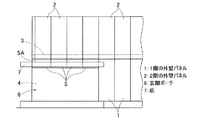
下階の外壁が上階の外壁よりも屋内側に入り込んだ入り玄関に庇を設ける場合、庇は玄関ポーチの上方に位置する垂れ壁に取り付けられる。下階の外壁パネルの上端と上階の外壁パネルの下端間の境界高さが階間の梁の上フランジの高さとほぼ同じである建物では、図7のように、前記垂れ壁5の上端が、前記梁3の上フランジ3aとほぼ同じ高さとなる。このような建物では、垂れ壁5の上下2箇所を、固定金物50を介して梁3の上フランジ3aおよび下フランジ3bにそれぞれ固定する。
When a wall is provided at the entrance where the outer wall of the lower floor enters the indoor side more than the outer wall of the upper floor, the wall is attached to the hanging wall located above the entrance porch. In a building where the boundary height between the upper end of the outer wall panel on the lower floor and the lower end of the outer wall panel on the upper floor is substantially the same as the height of the upper flange of the beam between the floors, as shown in FIG. However, it becomes substantially the same height as the
また、庇の出隅部については、図8のように、互いに角度を成す2つの垂れ壁5A,5Bの各上下2箇所を、それぞれ別々の固定金物50を介して梁3A,3Bに固定する。つまり出隅部では、計4個の固定金物50を用いて、垂れ壁5A,5Bが梁3A,3Bに固定される。
Further, as shown in FIG. 8, the upper and lower two portions of the two hanging
垂れ壁5がALC板や押出成形セメント板の場合は、垂れ壁5の下部に受け材を配置して固定される。
When the hanging
下階の外壁が上階の外壁よりも屋内側に入り込んだ入り玄関における庇の取付けに関して、例えば特許文献1,2に記載がある。但し、これらの特許文献には、この発明が対象とする、下階の外壁パネルの上端と上階の外壁パネルの下端間の境界高さが階間の梁の下フランジの高さとほぼ同じである建物における庇を取り付けるための構造は開示されていない。
For example,
外壁パネルと階間の梁との納まりの都合等から、下階の外壁パネルの上端および上階の外壁パネルの下端の高さが階間の梁の上フランジの高さとほぼ同じである従来の構成に代えて、図9のように、下階の外壁パネル1の上端と上階の外壁パネル(図示せず)の下端間の境界高さが階間の梁3の下フランジ3bの高さとほぼ同じである外壁を考えた。この外壁の場合、従来の固定金物50(図7、図8)を使用して梁3に垂れ壁5を固定しようとすると、図9に鎖線で示すように、垂れ壁5の上部だけが梁3に固定されることとなり、固定強度の低下が懸念される。
Conventionally, the height of the upper end of the outer wall panel on the lower floor and the lower end of the outer wall panel on the upper floor are almost the same as the height of the upper flange of the beam on the floor due to the convenience of the storage of the outer wall panel and the beam between the floors. Instead of the configuration, as shown in FIG. 9, the boundary height between the upper end of the
この発明の目的は、下階の外壁パネルの上端と上階の外壁パネルの下端間の境界高さが階間の梁の下フランジの高さと同じかまたは低い外壁において、少ない部品点数で梁に垂れ壁を強固に固定することができる建物の外壁構造を提供することである。 The object of the present invention is to provide a beam with a small number of parts on the outer wall where the boundary height between the upper end of the outer wall panel of the lower floor and the lower end of the outer wall panel of the upper floor is the same as or lower than the height of the lower flange of the beam. An object of the present invention is to provide a building outer wall structure capable of firmly fixing a hanging wall.
この発明の建物の外壁構造は、建物の外壁が、下階の外壁パネルの上端と上階の外壁パネルの下端間の境界高さが階間の梁の下フランジの高さと同じかまたは低く、前記外壁の一部には、前記上階の外壁パネルの下方に、前記下階の外壁パネルに代えて垂れ壁が配置され、この垂れ壁が前記梁に固定金物を介して固定され、前記固定金物は、前記梁の下フランジの下面に接合される水平板部と、この水平板部の一端から下方に前記垂れ壁の下部まで延び前記垂れ壁に接合される垂直板部とを有する。
この建物の外壁構造において、
前記梁はウェブが上下方向に沿うH形鋼であって、
前記固定金物の前記水平板部は前記梁の前記下フランジの下面における幅方向の全面に接し、
前記固定金物の前記水平板部は前記梁の前記ウェブの両側でボルトにより前記梁の前記下フランジに接合されてもよい。
In the outer wall structure of the building of the present invention, the outer wall of the building has a boundary height between the upper end of the outer wall panel on the lower floor and the lower end of the outer wall panel on the upper floor equal to or lower than the height of the lower flange of the beam between the floors. In the part of the outer wall, a hanging wall is disposed below the outer wall panel of the upper floor instead of the outer wall panel of the lower floor, and the hanging wall is fixed to the beam via a fixing metal, and the fixed hardware is that Yusuke a horizontal plate portion joined to the lower surface of the lower flange of the beam, and a vertical plate portion joined from one end of the horizontal plate section to the hanging wall extending to the bottom of the hanging wall downwardly .
In the outer wall structure of this building,
The beam is an H-shaped steel with a web extending in the vertical direction,
The horizontal plate portion of the fixed hardware is in contact with the entire surface in the width direction on the lower surface of the lower flange of the beam,
The horizontal plate portion of the fixed hardware may be joined to the lower flange of the beam by bolts on both sides of the web of the beam.
この構造によると、梁の下フランジの下面に固定金物の水平板部を接合し、かつ垂れ壁の側面に固定金物の垂直板部を接合することで、梁と垂れ壁とが固定金物を介して互いに固定される。固定金物の垂直板部の下端が垂れ壁の下部まで延びているため、垂れ壁の上下に広い範囲が固定金物に接合される。このため、梁に垂れ壁を強固に固定することができる。また、梁と垂れ壁との1つの固定箇所につき1つの固定金物だけを使用するため、使用する固定金物の数が少なくて済み、施工が容易である。 According to this structure, the horizontal plate portion of the fixed hardware is joined to the lower surface of the lower flange of the beam, and the vertical plate portion of the fixed hardware is joined to the side surface of the hanging wall, so that the beam and the hanging wall are interposed via the fixed hardware. Are fixed to each other. Since the lower end of the vertical plate portion of the fixed hardware extends to the lower portion of the hanging wall, a wide range is joined to the fixed hardware above and below the hanging wall. For this reason, the drooping wall can be firmly fixed to the beam. In addition, since only one fixed hardware is used for each fixed location between the beam and the hanging wall, the number of fixed hardware used is small, and the construction is easy.
この発明において、前記建物の出隅部を形成する平面視で互いに角度を成す2本の前記梁に2つの前記垂れ壁をそれぞれ固定するのに前記固定金物を用いる場合、前記固定金物は、前記2つの梁にそれぞれ接合される2つの前記水平板部と、前記2つの垂れ壁にそれぞれ接合される2つの前記垂直板部とを有し、これら2つの垂直板部が一体化されていると良い。
この構成であると、1つの固定金物で、建物の出隅部を形成する2本の梁に2つの垂れ壁をそれぞれ固定することができる。2つの垂直板部が一体化されていると、部品点数が削減されると共に面外方向の剛性が向上する。なお、「2つの垂直板部が一体化されている」とは、2つの垂直板部が1つの材料から折り曲げ加工等により成形されている場合、および元は別体である2つの垂直板部を溶接等により結合した場合の両方を含む。
In the present invention, when using the fixing hardware two of the hanging wall to fixed respectively to two said beams forming an angle with each other in plan view to form a external corner portion of the building, the fixing hardware, the And having the two horizontal plate portions joined to the two beams and the two vertical plate portions joined to the two hanging walls, respectively, and the two vertical plate portions are integrated. good.
With this configuration, the two hanging walls can be fixed to the two beams that form the projecting corner of the building with one fixed hardware. When the two vertical plate portions are integrated, the number of parts is reduced and the rigidity in the out-of-plane direction is improved. “Two vertical plate portions are integrated” means that the two vertical plate portions are formed of one material by bending or the like, and two vertical plate portions that are originally separate bodies. This includes both cases where these are joined by welding or the like.
この発明において、前記固定金物は、前記水平板部と前記垂直板部とを繋ぐリブを有すると良い。リブを有すると、固定金物の剛性が向上する。 In this invention, it is preferable that the fixed hardware has a rib connecting the horizontal plate portion and the vertical plate portion. When the rib is provided, the rigidity of the fixed hardware is improved.
この発明において、前記垂れ壁に庇が取り付けられていても良い。
垂れ壁が固定金物を介して梁に強固に固定されているため、垂れ壁に庇を取り付けることが可能である。
In the present invention, a hook may be attached to the hanging wall.
Since the drooping wall is firmly fixed to the beam via the fixed hardware, it is possible to attach a ridge to the drooping wall.
この発明の建物の外壁構造は、前記垂れ壁が外壁よりも建物の奥に入り込んだ玄関ポーチの上方に配置されている場合にも適用できる。 The outer wall structure of the building of the present invention can also be applied to the case where the hanging wall is disposed above the entrance porch that has entered the interior of the building more than the outer wall.
この発明の建物の外壁構造は、建物の外壁が、下階の外壁パネルの上端と上階の外壁パネルの下端間の境界高さが階間の梁の下フランジの高さと同じかまたは低く、前記外壁の一部には、前記上階の外壁パネルの下方に、前記下階の外壁パネルに代えて垂れ壁が配置され、この垂れ壁が前記梁に固定金物を介して固定され、前記固定金物は、前記梁の下フランジの下面に接合される水平板部と、この水平板部の一端から下方に前記垂れ壁の下部まで延び前記垂れ壁に接合される垂直板部とを有するため、少ない部品点数で梁に垂れ壁を強固に固定することができる。 In the outer wall structure of a building according to the present invention, the outer wall of the building has a boundary height between the upper end of the outer wall panel on the lower floor and the lower end of the outer wall panel on the upper floor equal to or lower than the height of the lower flange of the beam between the floors. In the part of the outer wall, a hanging wall is arranged below the outer wall panel of the upper floor instead of the outer wall panel of the lower floor, and the hanging wall is fixed to the beam via a fixing hardware, and the fixed Since the hardware has a horizontal plate portion joined to the lower surface of the lower flange of the beam, and a vertical plate portion extending from one end of the horizontal plate portion to the lower portion of the hanging wall and joined to the hanging wall, The hanging wall can be firmly fixed to the beam with a small number of parts.
この発明の一実施形態を図1〜図5と共に説明する。
図1はこの発明の一実施形態にかかる外壁構造が適用された建物の玄関周辺の正面図である。同図に示すように、この建物は2階建てで、各階の外壁が外壁パネル1,2で構成されている。玄関4は1階の隅部に設けられている。玄関4の上側部分には、1階の外壁パネル1に代えて垂れ壁5が設けられる。そして、この垂れ壁5に、玄関ポーチ6に被さる庇7が取り付けられる。図の例の建物の場合、1階が請求項で言う「下階」であり、2階が請求項で言う「上階」である。
An embodiment of the present invention will be described with reference to FIGS.
FIG. 1 is a front view around the entrance of a building to which an outer wall structure according to one embodiment of the present invention is applied. As shown in the figure, this building has two floors, and the outer wall of each floor is composed of
1階の外壁パネル1の上端と2階の外壁パネル2の下端間の境界高さは、階間の梁3の下端の高さとほぼ同じである。詳しくは、1階の外壁パネル1の上端および2階の外壁パネル2の下端の高さは、梁3の下端の高さよりも少し低い。
The boundary height between the upper end of the
図2は同玄関周辺の梁、垂れ壁、および庇を示す水平断面図である。この建物の玄関4は、外壁よりも建物の奥に入り込んだ入り玄関である。玄関4上側の出隅部では、階間の梁3として前後梁3Aおよび左右梁3Bを有し、これら前後梁3Aおよび左右梁3Bが梁接合金物3Cを介して互いに直角となるように接合されている。また、前記垂れ壁5として前後垂れ壁5Aおよび左右垂れ壁5Bを有し、これら前後垂れ壁5Aおよび左右垂れ壁5B間にコーナー垂れ壁5Cが介在している。なお、以下の説明では、前後梁3A、左右梁3Bを単に「梁3」を呼称する場合があると共に、前後垂れ壁5A、左右垂れ壁5Bを単に「垂れ壁5」を呼称する場合がある。
FIG. 2 is a horizontal sectional view showing a beam, a hanging wall, and a fence around the entrance. The
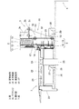
図3は庇取付部の破断側面図、具体的には図2のIII−III断面図である。梁3はH形鋼からなり、ウェブ3cが上下を向くように設置されている。2階の外壁パネル2は、外壁フレーム10と、断熱材11と、外装下地材12と、外装材13とからなる。外壁フレーム10は、例えば溝形鋼からなる縦材および横材を四角形の枠状に組んだものであり、枠内に前記断熱材11が充填される。図3には1階の外壁パネル1は図示されていないが、1階の外壁パネル1も2階の外壁パネル2と同じ構造である。
FIG. 3 is a cutaway side view of the saddle mounting portion, specifically a III-III cross-sectional view of FIG. The
2階の外壁パネル2の下側には、前記垂れ壁5が配置されている。垂れ壁5は、垂れ壁フレーム15と庇用下地材16とからなる。垂れ壁フレーム15は、外壁フレーム10と同様に溝形鋼からなる縦材および横材を四角形の枠状に組んだものである。垂れ壁フレーム15の枠内に断熱材は充填されない。
The hanging
2階の外壁パネル2と垂れ壁5との間には、水切り用隙間17が形成されている。この水切り用隙間17は、2階の外壁パネル2の外装材13の下方に開口している。水切り用隙間17の開口には、雨水が内部に入るのを防ぐ水切りカバー18が取り付けられている。
A draining
庇7は、垂れ壁5の庇用下地材16に木ねじ等の固定具20で固定された庇骨組21と、この庇骨組21の上に設置された屋根材22と、庇骨組21の端縁に取り付けられた鼻隠し23とを有する。屋根材22にはドレン24が設けられ、このドレン24に排水管25が接続されている。庇骨組21の下側には水平状に軒天面材26が設けられ、この軒天面材26が垂れ壁5の下方を通って玄関4の上方まで延びている。軒天面材26は、庇骨組21および垂れ壁5の垂れ壁フレーム15にそれぞれ設置された軒天下地材27,28に、木ねじ等の固定具29で固定される。
The
前記垂れ壁5は、後述の固定金物30,40を介して梁3に固定される。固定金物30,40には、図4に示す直線部用のものと、図5に示す出隅部用のものとがある。
図4に示すように、直線部用の固定金物30は、梁3の下フランジ3bの下面に接合される水平板部31と、この水平板部31の一端から下方に延び垂れ壁5の垂れ壁フレーム15に接合される垂直板部32と、これら水平板部31と垂直板部32とを繋ぐリブ33とで構成される。
The hanging
As shown in FIG. 4, the fixed
水平板部31には、梁3の下フランジ3bに接合するためのボルト挿通孔34が、リブ33を挟んで両側に2個ずつ設けられている。図4(C)における左列のボルト挿通孔34には、下フランジ3bのウェブ3cよりも左側の部分に接合するためのボルトが挿通され、右列のボルト挿通孔34には、下フランジ3bのウェブ3cよりも右側の部分に接合するためのボルトが挿通される。
The horizontal
垂直板部32には、垂れ壁5の垂れ壁フレーム15に接合するためのボルト挿通孔35が、リブ33を挟んで両側に2個ずつ設けられている。上列のボルト挿通孔35には、垂れ壁フレーム15の上の横材である溝形鋼のフランジに接合するためのボルトが挿通され、右列のボルト挿通孔35には、下の横材である溝形鋼のフランジに接合するためのボルトが挿通される。
The
この実施形態の場合、水平板部31と垂直板部32は同じ幅であり、1枚の鋼板を折り曲げて両部31,32が成形されている。水平板部31および垂直板部32は、2枚の鋼板を溶接等により接合して成形してもよい。リブ33は三角形状で、溶接により水平板部31および垂直板部32に接合されている。このようにリブ33を設けることで、固定金物30の剛性が向上する。
In the case of this embodiment, the
図5に示すように、出隅部用の固定金物40は、出隅部を形成する前後梁3Aおよび左右梁3Bにそれぞれ接合される2つの水平板部41A,41Bと、前後垂れ壁5Aおよび左右垂れ壁5Bにそれぞれ接合される2つの垂直板部42A,42Bとを有する。水平板部41Aと垂直板部42Aとの間、および水平板部41Bと垂直板部42Bとの間には、それぞれリブ43A,43Bが設けられている。
As shown in FIG. 5, the fixed
2つの垂直板部42A,42Bは、1枚の鋼板を平面視で直角に折り曲げて成形されている。水平板部41A,41Bは、垂直板部42A,42Bの上端縁における折り曲げ位置Pからそれぞれ所定距離だけ離れた箇所に位置している。前記所定距離は、前記梁接合金物3Cの一辺の長さと同じか、または少しだけ長い値である。固定金物40の使用状態において、図5(C)に示すように、2つの垂直板部42A,42Bにおける水平板部41A,41Bの存在しない部分と、2つの水平板部41A,41Bとで囲まれた空間Sに、梁接合金物3Cが配置されるようになっている。
The two
水平板部41A,41Bは、固定金物40の使用状態において梁接合金物3Cとの干渉を避けるために、折り曲げ位置Pに近い側の角部がそれぞれ平面視で三角形に切り欠かれている。水平板部41A,41Bには、縦梁3Aおよび横梁3Bの各下フランジ3b,3bに接合するためのボルト挿通孔44が、折り曲げ位置Pから見てリブ43A,43Bの外側に2つ、内側に1つ設けられている。
In the
垂直板部42A,42Bには、前後垂れ壁5Aおよび左右垂れ壁5Bの各垂れ壁フレーム15に接合するためのボルト挿通孔45が、折り曲げ位置Pから見てリブ43A,43Bの内側に2つ設けられている。上のボルト挿通孔45には、垂れ壁フレーム15の上の横材である溝形鋼のフランジに接合するためのボルトが挿通され、右のボルト挿通孔45には、下の横材である溝形鋼のフランジに接合するためのボルトが挿通される。
The
この出隅部用の固定金物40は、2つの垂直板部42A,42Bが平面視でL字状を成す一体型としたため、部品点数を削減することができると共に、面外方向の剛性が強化されている。この実施形態の場合、水平板部41A,41Bおよび垂直板部42A,42Bが1枚の鋼板を折り曲げて成形されているが、水平板部41A,41Bをそれぞれ別体で形成しておき、垂直板部42A,42Bに前記別体の水平板部41A,41Bを溶接等で接合してもよい。リブ43A,43Bは、溶接により水平板部41A,41Bおよび垂直板部42A,42Bに接合されている。このようにリブ43A,43Bを設けることで、固定金物40の剛性が向上する。
Since the fixed
図3は図2のIII−III断面図であり、直線部用の固定金物30を介して梁3に垂れ壁5が固定された状態を示している。具体的には、梁3の下フランジ3bの下面に固定金物30の水平板部31がボルト・ナット51で接合され、かつ垂れ壁5の垂れ壁フレーム15の上下の横材である溝形鋼の各フランジに固定金物30の垂直板部32がボルト・ナット52で接合されている。つまり、固定金物30の垂直板部31の下端が垂れ壁5の下端付近まで延びているため、垂れ壁5の上下に広い範囲が垂直板部31に接合される。これにより、梁3に垂れ壁5を強固に固定することができる。また、梁3と垂れ壁5との1つの固定箇所につき1つの固定金物30だけを使用するため、使用する固定金物30の数が少なくて済み、施工が容易である。
FIG. 3 is a cross-sectional view taken along the line III-III in FIG. 2 and shows a state in which the
また、図2に示すように、出隅部では、出隅部用の固定金物40を介して、前後梁3Aおよび左右梁3Bに前後垂れ壁5Aおよび左右垂れ壁5Bがそれぞれ固定される。出隅部用の固定金物40は、前後梁3Aおよび左右梁3Bにそれぞれ接合される2つの水平板部41A,41B(図5)と、前後垂れ壁5Aおよび左右垂れ壁5Bにそれぞれ接合される2つの垂直板部42A,42B(図5)とを有するため、1つの固定金物40で、出隅部を形成する2本の梁3A,3Bに2つの垂れ壁5A,5Bをそれぞれ固定することができる。梁3A,3Bと水平板部41A,41Bとの接合構造、および垂れ壁5A,5Bと垂直板部42A,42Bとの接合構造は、前記直線部用の固定金物30の場合と同様である。
In addition, as shown in FIG. 2, the front and
このように、直線部用および出隅部用の固定金物30,40を用いることで、少ない固定金物30,40で梁3に垂れ壁5を強固に固定することができる。特に、出隅部用の固定金物40を2つの垂直板部42A,42Bが平面視でL字状を成す一体型としたため、面外方向の剛性が向上している。このため、庇7に積雪、風圧等の荷重が作用した場合でも、その荷重に垂れ壁5が耐えることができ、庇7の撓みが抑制される。
As described above, by using the fixed
出隅部用の固定金物40を使用することの効果を確かめるために、試験を行った。試験は、庇7に荷重をかけ固定金物40の下端の変位量を測定した。この試験を、出隅部用の固定金物40を使用した場合(金物L型)、および2つの直線部用の固定金物30を使用した場合(金物分割)につき行った。図6が、その試験結果である。両者を比較すると、積雪設計荷重である荷重470kgで、金物L型の方が金物分割よりも変位量で約5mmの低減効果があることが分かる。
A test was conducted to confirm the effect of using the fixed
また、直線部用および出隅部用の固定金物30,40を用いると、使用する固定金物30,40の数が少なくて済む。例えば、従来、出隅部では4個の固定金物50(図6、図7)で梁3に垂れ壁5を固定したのに対し、1個の出隅部用の固定金物40で梁3に垂れ壁5を固定することができる。このため、施工工数が削減され、施工が容易となる。
Further, when the fixed
さらに、この実施形態の外壁構造では、垂れ壁5がALC板や押出成形セメント板ではなく、溝形鋼を四角形に組んだ垂れ壁フレーム15が採用されているため、垂れ壁5の下部に受け材を配置して固定する必要がなく、さらなる部品点数の削減が図られている。
Furthermore, in the outer wall structure of this embodiment, the drooping
1…1階の外壁パネル
2…2階の外壁パネル
3…梁
3A…前後梁
3B…左右梁
3b…下フランジ
5…垂れ壁
5A…前後垂れ壁
5B…左右垂れ壁
6…玄関ポーチ
7…庇
30,40…固定金物
31,41A,41B…水平板部
32,42A,42B…垂直板部
33,43…リブ
DESCRIPTION OF
Claims (5)
前記外壁の一部には、前記上階の外壁パネルの下方に、前記下階の外壁パネルに代えて垂れ壁が配置され、この垂れ壁が前記梁に固定金物を介して固定され、
前記固定金物は、前記梁の下フランジの下面に接合される水平板部と、この水平板部の一端から下方に前記垂れ壁の下部まで延び前記垂れ壁に接合される垂直板部とを有し、
前記梁はウェブが上下方向に沿うH形鋼であって、
前記固定金物の前記水平板部は前記梁の前記下フランジの下面における幅方向の全面に接し、
前記固定金物の前記水平板部は前記梁の前記ウェブの両側でボルトにより前記梁の前記下フランジに接合された
ことを特徴とする建物の外壁構造。 The outer wall of the building is a building outer wall structure in which the boundary height between the upper end of the lower-floor outer wall panel and the lower end of the upper-floor outer wall panel is the same as or lower than the lower flange height of the beam between the floors,
In the part of the outer wall, a hanging wall is disposed below the outer wall panel on the upper floor instead of the outer wall panel on the lower floor, and the hanging wall is fixed to the beam via a fixing metal,
The fixed hardware has a horizontal plate portion joined to the lower surface of the lower flange of the beam, and a vertical plate portion that extends downward from one end of the horizontal plate portion to a lower portion of the hanging wall and is joined to the hanging wall. And
The beam is an H-shaped steel with a web extending in the vertical direction,
The horizontal plate portion of the fixed hardware is in contact with the entire surface in the width direction on the lower surface of the lower flange of the beam,
The outer wall structure of a building, wherein the horizontal plate portion of the fixed hardware is joined to the lower flange of the beam by bolts on both sides of the web of the beam .
前記外壁の一部には、前記上階の外壁パネルの下方に、前記下階の外壁パネルに代えて垂れ壁が配置され、この垂れ壁が前記梁に固定金物を介して固定され、
前記固定金物は、前記梁の下フランジの下面に接合される水平板部と、この水平板部の一端から下方に前記垂れ壁の下部まで延び前記垂れ壁に接合される垂直板部とを有し、
前記建物の出隅部を形成する平面視で互いに角度を成す2本の前記梁に2つの前記垂れ壁をそれぞれ固定するのに前記固定金物が用いられ、前記2つの梁にそれぞれ接合される2つの前記水平板部と、前記2つの垂れ壁にそれぞれ接合される2つの前記垂直板部とを有し、これら2つの垂直板部が一体化されている建物の外壁構造。 The outer wall of the building is a building outer wall structure in which the boundary height between the upper end of the lower floor outer wall panel and the lower end of the upper floor outer wall panel is the same as or lower than the lower flange height of the beam between the floors,
In the part of the outer wall, a hanging wall is disposed below the outer wall panel of the upper floor instead of the outer wall panel of the lower floor, and the hanging wall is fixed to the beam via a fixing metal,
The fixed hardware has a horizontal plate portion joined to the lower surface of the lower flange of the beam, and a vertical plate portion extending downward from one end of the horizontal plate portion to the lower portion of the hanging wall and joined to the hanging wall. And
The fixed hardware is used to fix the two hanging walls to the two beams that form an angle with each other in a plan view that forms the projecting corner of the building, and is joined to the two beams, respectively. An outer wall structure of a building having two horizontal plate portions and two vertical plate portions respectively joined to the two hanging walls, and these two vertical plate portions are integrated.
Priority Applications (1)
| Application Number | Priority Date | Filing Date | Title |
|---|---|---|---|
| JP2015124580A JP6591799B2 (en) | 2015-06-22 | 2015-06-22 | Building outer wall structure |
Applications Claiming Priority (1)
| Application Number | Priority Date | Filing Date | Title |
|---|---|---|---|
| JP2015124580A JP6591799B2 (en) | 2015-06-22 | 2015-06-22 | Building outer wall structure |
Publications (2)
| Publication Number | Publication Date |
|---|---|
| JP2017008571A JP2017008571A (en) | 2017-01-12 |
| JP6591799B2 true JP6591799B2 (en) | 2019-10-16 |
Family
ID=57761116
Family Applications (1)
| Application Number | Title | Priority Date | Filing Date |
|---|---|---|---|
| JP2015124580A Active JP6591799B2 (en) | 2015-06-22 | 2015-06-22 | Building outer wall structure |
Country Status (1)
| Country | Link |
|---|---|
| JP (1) | JP6591799B2 (en) |
Family Cites Families (5)
| Publication number | Priority date | Publication date | Assignee | Title |
|---|---|---|---|---|
| JPH0670336B2 (en) * | 1990-10-15 | 1994-09-07 | ナショナル住宅産業株式会社 | External wall panel mounting structure |
| JPH0833038B2 (en) * | 1990-10-15 | 1996-03-29 | ナショナル住宅産業株式会社 | Concrete panel mounting structure for vertical walls |
| JP2001115579A (en) * | 1999-10-20 | 2001-04-24 | Sekisui House Ltd | Attaching structure of outer wall panel |
| JP2009203739A (en) * | 2008-02-28 | 2009-09-10 | Toyota Home Kk | Building and its construction method |
| JP2009270299A (en) * | 2008-05-02 | 2009-11-19 | Sekisui House Ltd | Eaves |
-
2015
- 2015-06-22 JP JP2015124580A patent/JP6591799B2/en active Active
Also Published As
| Publication number | Publication date |
|---|---|
| JP2017008571A (en) | 2017-01-12 |
Similar Documents
| Publication | Publication Date | Title |
|---|---|---|
| JP6283335B2 (en) | Exterior structure | |
| JP6151511B2 (en) | Exterior wall structure | |
| JP5329174B2 (en) | Outside heat insulation structure | |
| JP6645193B2 (en) | Horizontal material, structure for mounting surface material using horizontal material, and structure for mounting surface material and frame material using horizontal material | |
| JP6591799B2 (en) | Building outer wall structure | |
| JP4691203B1 (en) | Building reinforcement structure | |
| JP5461279B2 (en) | building | |
| JP5873369B2 (en) | Building overhang structure | |
| JP6368272B2 (en) | Handrail mounting structure on balcony | |
| JP7164394B2 (en) | Roof structure with eaves gutter | |
| JP2018197451A (en) | Simplified structure | |
| JP2012167462A (en) | Joint member, joint structure using the same, and steel-frame building | |
| JP6250929B2 (en) | Exterior wall structure | |
| JP6265677B2 (en) | External overhang structure | |
| JP4691202B1 (en) | Building reinforcement structure | |
| KR102096099B1 (en) | Assembling structure of curtain wall frame | |
| JP6423165B2 (en) | Surface grid mounting structure | |
| JP4248596B1 (en) | Exterior structure | |
| JP4691201B1 (en) | Building reinforcement structure | |
| JP5934059B2 (en) | How to install a unit building | |
| JP6918590B2 (en) | handrail | |
| JP6886382B2 (en) | balcony | |
| JP6904867B2 (en) | Connecting girders and balconies with them | |
| JP6904868B2 (en) | balcony | |
| JP6581354B2 (en) | building |
Legal Events
| Date | Code | Title | Description |
|---|---|---|---|
| A621 | Written request for application examination |
Free format text: JAPANESE INTERMEDIATE CODE: A621 Effective date: 20180531 |
|
| A977 | Report on retrieval |
Free format text: JAPANESE INTERMEDIATE CODE: A971007 Effective date: 20190213 |
|
| A131 | Notification of reasons for refusal |
Free format text: JAPANESE INTERMEDIATE CODE: A131 Effective date: 20190305 |
|
| A521 | Request for written amendment filed |
Free format text: JAPANESE INTERMEDIATE CODE: A523 Effective date: 20190419 |
|
| TRDD | Decision of grant or rejection written | ||
| A01 | Written decision to grant a patent or to grant a registration (utility model) |
Free format text: JAPANESE INTERMEDIATE CODE: A01 Effective date: 20190903 |
|
| A61 | First payment of annual fees (during grant procedure) |
Free format text: JAPANESE INTERMEDIATE CODE: A61 Effective date: 20190919 |
|
| R150 | Certificate of patent or registration of utility model |
Ref document number: 6591799 Country of ref document: JP Free format text: JAPANESE INTERMEDIATE CODE: R150 |
|
| R250 | Receipt of annual fees |
Free format text: JAPANESE INTERMEDIATE CODE: R250 |