JP2012241120A - Gasification system - Google Patents
Gasification system Download PDFInfo
- Publication number
- JP2012241120A JP2012241120A JP2011113331A JP2011113331A JP2012241120A JP 2012241120 A JP2012241120 A JP 2012241120A JP 2011113331 A JP2011113331 A JP 2011113331A JP 2011113331 A JP2011113331 A JP 2011113331A JP 2012241120 A JP2012241120 A JP 2012241120A
- Authority
- JP
- Japan
- Prior art keywords
- gas
- fuel
- supplied
- gasification
- coal
- Prior art date
- Legal status (The legal status is an assumption and is not a legal conclusion. Google has not performed a legal analysis and makes no representation as to the accuracy of the status listed.)
- Withdrawn
Links
Images
Classifications
-
- Y—GENERAL TAGGING OF NEW TECHNOLOGICAL DEVELOPMENTS; GENERAL TAGGING OF CROSS-SECTIONAL TECHNOLOGIES SPANNING OVER SEVERAL SECTIONS OF THE IPC; TECHNICAL SUBJECTS COVERED BY FORMER USPC CROSS-REFERENCE ART COLLECTIONS [XRACs] AND DIGESTS
- Y02—TECHNOLOGIES OR APPLICATIONS FOR MITIGATION OR ADAPTATION AGAINST CLIMATE CHANGE
- Y02E—REDUCTION OF GREENHOUSE GAS [GHG] EMISSIONS, RELATED TO ENERGY GENERATION, TRANSMISSION OR DISTRIBUTION
- Y02E20/00—Combustion technologies with mitigation potential
- Y02E20/16—Combined cycle power plant [CCPP], or combined cycle gas turbine [CCGT]
- Y02E20/18—Integrated gasification combined cycle [IGCC], e.g. combined with carbon capture and storage [CCS]
-
- Y—GENERAL TAGGING OF NEW TECHNOLOGICAL DEVELOPMENTS; GENERAL TAGGING OF CROSS-SECTIONAL TECHNOLOGIES SPANNING OVER SEVERAL SECTIONS OF THE IPC; TECHNICAL SUBJECTS COVERED BY FORMER USPC CROSS-REFERENCE ART COLLECTIONS [XRACs] AND DIGESTS
- Y02—TECHNOLOGIES OR APPLICATIONS FOR MITIGATION OR ADAPTATION AGAINST CLIMATE CHANGE
- Y02P—CLIMATE CHANGE MITIGATION TECHNOLOGIES IN THE PRODUCTION OR PROCESSING OF GOODS
- Y02P20/00—Technologies relating to chemical industry
- Y02P20/10—Process efficiency
- Y02P20/129—Energy recovery, e.g. by cogeneration, H2recovery or pressure recovery turbines
Abstract
Description
本発明は、褐炭等の湿潤燃料を乾燥させて乾燥燃料とし、乾燥燃料をガス化して燃料ガスとするガス化システムに関するものである。 The present invention relates to a gasification system in which wet fuel such as lignite is dried to obtain dry fuel, and the dry fuel is gasified to produce fuel gas.
従来、このようなガス化システムとして、石炭を粉砕・乾燥して微粉燃料とし、微粉燃料をガス化炉に供給してガス化し、石炭ガスをガスタービンに供給して発電を行い、ガスタービンの排ガスを排熱回収ボイラに導入して蒸気を発生し、発生蒸気を蒸気タービンに供給して発電を行う石炭焚複合発電設備が知られている(例えば、特許文献1参照)。 Conventionally, as such a gasification system, coal is pulverized and dried to make a fine powder fuel, the fine powder fuel is supplied to a gasification furnace for gasification, and the coal gas is supplied to a gas turbine to generate power. There is known a coal-fired combined power generation facility in which exhaust gas is introduced into an exhaust heat recovery boiler to generate steam, and the generated steam is supplied to a steam turbine to generate power (see, for example, Patent Document 1).
ところで、従来の石炭焚複合発電設備のようなガス化システムにおいて、ガスタービンによる発電を行わない場合、ガス化炉を有効活用すべく、ガス化炉でガス化した石炭ガスからメタノールやジメチルエーテル等の液体燃料を合成する燃料合成装置を併設している。燃料合成装置を用いて燃料合成を行う場合、空気分離装置において分離された酸素は、ガス化炉への供給量が多くなる。このため、空気分離装置において分離された窒素が余ってしまい、窒素を有効に活用することが困難であった。 By the way, in a gasification system such as a conventional coal-fired combined power generation facility, when power generation by a gas turbine is not performed, methanol, dimethyl ether, etc. are used from coal gas gasified in the gasification furnace in order to effectively use the gasification furnace. A fuel synthesizer that synthesizes liquid fuel is also provided. When fuel synthesis is performed using a fuel synthesizing apparatus, the amount of oxygen separated in the air separation apparatus is supplied to the gasifier. For this reason, the nitrogen separated in the air separation device is left, and it is difficult to effectively use the nitrogen.
そこで、本発明は、燃料合成時において、窒素を有効に活用しながら、湿潤燃料を効率良く乾燥させることが可能なガス化システムを提供することを課題とする。 Therefore, an object of the present invention is to provide a gasification system capable of efficiently drying wet fuel while effectively utilizing nitrogen during fuel synthesis.
本発明のガス化システムは、流動化ガスによって流動する湿潤燃料を、内部に設けた伝熱管により加熱することで乾燥燃料とする流動層乾燥装置と、空気を窒素と酸素とに分離可能な空気分離装置と、空気分離装置から供給される酸素を用いて、乾燥燃料をガス化してガス化ガスとするガス化炉と、ガス化炉でガス化されたガス化ガスを燃焼させることにより発電可能な発電装置と、ガス化炉でガス化されたガス化ガスを用いて、液体燃料を合成可能な燃料合成装置と、を備え、発電装置による発電運転時において、発電装置には、ガス化ガスが供給され、流動層乾燥装置には、流動化ガスとして蒸気が供給される一方で、流動化ガスとして空気分離装置から窒素が供給されず、伝熱管の内部には、高温流体が流通し、燃料合成装置による燃料合成時において、燃料合成装置には、ガス化ガスが供給され、流動層乾燥装置には、流動化ガスとして蒸気が供給されると共に、流動化ガスとして空気分離装置から窒素が供給され、伝熱管の内部には、高温流体に比して低温となる低温流体が流通することを特徴とする。 A gasification system according to the present invention includes a fluidized bed drying apparatus that uses wet fuel flowing by a fluidizing gas as a dry fuel by heating it with a heat transfer tube provided therein, and air that can separate air into nitrogen and oxygen. Power generation is possible by burning the gasification gas gasified in the gasification furnace and the gasification furnace that gasifies the dry fuel into gasification gas using oxygen supplied from the separation device and air separation device And a fuel synthesizing device capable of synthesizing liquid fuel using gasified gas gasified in a gasification furnace. During power generation operation by the power generating device, the power generating device includes gasified gas. In the fluidized bed drying apparatus, steam is supplied as fluidizing gas, while nitrogen is not supplied from the air separation apparatus as fluidizing gas, and a high-temperature fluid circulates inside the heat transfer tube, Fuel synthesis equipment At the time of synthesis, gasification gas is supplied to the fuel synthesizing device, steam is supplied as fluidizing gas to the fluidized bed drying device, and nitrogen is supplied as fluidizing gas from the air separation device, and the heat transfer tube A low-temperature fluid having a temperature lower than that of the high-temperature fluid circulates in the interior of the.
この構成によれば、燃料合成装置により液体燃料を合成する場合、空気分離装置で分離される酸素の使用量が多くなり、分離された余剰の窒素は、流動化ガスとして流動層乾燥装置に供給することができる。このため、燃料合成時において余剰となる窒素を有効に活用することができる。このとき、窒素は非凝縮性ガスであるため、窒素を流動化ガスとして用いると、凝縮性ガスである蒸気を流動化ガスとして用いる場合に比して、低温で湿潤燃料を乾燥することができる。これにより、伝熱管に供給する流体を低温流体とすることができ、湿潤燃料の乾燥の効率化を図ることができる。なお、低温流体は、ガス化炉の発電運転時の蒸気による流動化の際に、伝熱管に流通する高温流体に較べて低温である。 According to this configuration, when liquid fuel is synthesized by the fuel synthesizing apparatus, the amount of oxygen separated by the air separation apparatus increases, and the separated excess nitrogen is supplied to the fluidized bed drying apparatus as fluidized gas. can do. For this reason, surplus nitrogen at the time of fuel synthesis can be effectively utilized. At this time, since nitrogen is a non-condensable gas, when nitrogen is used as the fluidizing gas, the wet fuel can be dried at a lower temperature than when vapor, which is a condensable gas, is used as the fluidizing gas. . Thereby, the fluid supplied to a heat exchanger tube can be made into a low-temperature fluid, and the drying efficiency of wet fuel can be achieved. Note that the low-temperature fluid has a lower temperature than the high-temperature fluid flowing through the heat transfer tube when fluidizing with steam during the power generation operation of the gasifier.
この場合、発電装置において燃焼するガス化ガスの排熱を回収する排熱回収装置をさらに備え、流動化ガスとして供給される蒸気は、排熱回収装置によって回収された排熱によって発生する蒸気であることが好ましい。 In this case, the apparatus further includes an exhaust heat recovery device that recovers exhaust heat of the gasified gas combusted in the power generation device, and the steam supplied as the fluidizing gas is steam generated by the exhaust heat recovered by the exhaust heat recovery device. Preferably there is.
この構成によれば、ガス化ガスの排熱によって発生する蒸気を利用することができるため、湿潤燃料をさらに効率良く乾燥させることができる。 According to this configuration, steam generated by exhaust heat of the gasification gas can be used, so that the wet fuel can be dried more efficiently.
この場合、ガス化炉でガス化されたガス化ガスの不純物を除去するガス精製装置をさらに備え、低温流体は、ガス精製装置から得られる熱媒であることが好ましい。 In this case, it is preferable to further include a gas purification device that removes impurities of the gasification gas gasified in the gasification furnace, and the low-temperature fluid is a heat medium obtained from the gas purification device.
この構成によれば、ガス精製装置から得られる熱媒を利用することができるため、湿潤燃料をさらに効率良く乾燥させることができる。 According to this configuration, since the heat medium obtained from the gas purifier can be used, the wet fuel can be dried more efficiently.
本発明のガス化システムによれば、燃料合成時において、余剰となる窒素を流動化ガスとして流動層乾燥装置に供給することができるため、窒素を有効に活用することができ、また、伝熱管に供給する流体を低温流体とすることができるため、湿潤燃料の乾燥の効率化を図ることができる。 According to the gasification system of the present invention, surplus nitrogen can be supplied as a fluidizing gas to the fluidized bed drying apparatus at the time of fuel synthesis, so that nitrogen can be effectively utilized, and the heat transfer tube Since the fluid supplied to the fuel can be a low-temperature fluid, the efficiency of drying the wet fuel can be improved.
以下、添付した図面を参照して、本発明に係るガス化システムについて説明する。なお、以下の実施例によりこの発明が限定されるものではない。また、下記実施例における構成要素には、当業者が置換可能かつ容易なもの、或いは実質的に同一のものが含まれる。 Hereinafter, a gasification system according to the present invention will be described with reference to the accompanying drawings. The present invention is not limited to the following examples. In addition, constituent elements in the following embodiments include those that can be easily replaced by those skilled in the art or those that are substantially the same.
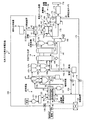
図1は、本実施例に係る石炭ガス化複合発電設備の概略構成図である。本実施例のガス化システムは、いわゆる、石炭ガス化複合発電設備(IGCC:Integrated Coal Gasification Combined Cycle)10である。石炭ガス化複合発電設備10は、空気を酸化剤としてガス化炉で石炭ガスを生成する空気燃焼方式を採用し、ガス精製装置16で精製した後の石炭ガスをガス化ガスとしてガスタービン設備17に供給して発電を行っている。すなわち、本実施例の石炭ガス化複合発電設備10は、空気燃焼方式(空気吹き)の発電設備である。この場合、ガス化炉に供給する湿潤原料として褐炭を使用している。
FIG. 1 is a schematic configuration diagram of the combined coal gasification combined power generation facility according to the present embodiment. The gasification system of this embodiment is a so-called coal gasification combined cycle facility (IGCC: Integrated Coal Gasification Combined Cycle) 10. The combined coal gasification combined
なお、本実施例では、湿潤原料として褐炭を適用したが、水分含量の高いものであれば、亜瀝青炭等を含む低品位炭や、スラッジ等の泥炭を適用してもよく、また、高品位炭であっても適用可能である。また、湿潤原料として、褐炭等の石炭に限らず、再生可能な生物由来の有機性資源として使用されるバイオマスであってもよく、例えば、間伐材、廃材木、流木、草類、廃棄物、汚泥、タイヤ及びこれらを原料としたリサイクル燃料(ペレットやチップ)などを使用することも可能である。 In this example, lignite was applied as a wet raw material, but low-grade coal including subbituminous coal, peat such as sludge, etc. may be applied as long as the moisture content is high. Even charcoal is applicable. In addition, the wet raw material is not limited to coal such as lignite, but may be biomass used as organic resources derived from renewable organisms. For example, thinned wood, waste wood, driftwood, grass, waste, It is also possible to use sludge, tires, and recycled fuel (pellets and chips) made from these raw materials.
本実施例において、図1に示すように、石炭ガス化複合発電設備10は、給炭装置11、流動層乾燥装置12、微粉炭機(ミル)13、石炭ガス化炉14、チャー回収装置15、ガス精製装置16、ガスタービン設備17と蒸気タービン設備18と発電機19とからなる発電設備(発電装置)22、排熱回収ボイラ(HRSG:Heat Recovery Steam Generator)20、燃料合成装置21、これらを制御する制御装置23を有している。
In this embodiment, as shown in FIG. 1, the coal gasification combined
給炭装置11は、原炭バンカ121と、石炭供給機122と、クラッシャ123とを有している。原炭バンカ121は、褐炭を貯留可能であって、所定量の褐炭を石炭供給機122に投下する。石炭供給機122は、原炭バンカ121から投下された褐炭をコンベアなどにより搬送し、クラッシャ123に投下する。このクラッシャ123は、投下された褐炭を細かく破砕して細粒化する。
The coal feeder 11 includes a
流動層乾燥装置12は、給炭装置11により投入された褐炭を、流動化ガスにより流動させながら、加熱乾燥させるものである。流動層乾燥装置12は、内部に褐炭が供給される乾燥炉30と、乾燥炉30の内部に設けられたガス分散板31と、を備えている。乾燥炉30は、長方体の箱状に形成されている。ガス分散板31は、乾燥炉30内部の空間を、鉛直方向下方側(図示下側)に位置するチャンバ室35と、鉛直方向上方側(図示上側)に位置する乾燥室36とに区分けしている。ガス分散板31には、多数の貫通孔が形成され、チャンバ室35には、蒸気や窒素等の流動化ガスが導入される。これにより、乾燥炉30に供給された褐炭は、流動化ガスにより流動することで、乾燥炉30内に流動層25を形成する。また、流動層乾燥装置12は、流動層25内に設けられた伝熱管38を有している。この伝熱管38の内部には、流体流入ライン39を介して乾燥用蒸気(高温流体)が流入する。この流体流入ライン39には、伝熱管用第1開閉弁40が介設されており、伝熱管用第1開閉弁40が開弁して乾燥用蒸気が流入すると、伝熱管38は、流体の潜熱を利用して、乾燥室36内の褐炭を乾燥させる。
The fluidized
この流動層乾燥装置12には、下部から取り出された乾燥済の褐炭(乾燥炭)を冷却する冷却器131が接続され、乾燥冷却済の乾燥炭は、冷却器131に接続された乾燥炭バンカ132に貯留される。また、流動層乾燥装置12は、上部から排出された排出ガスから乾燥炭の粒子を分離する乾燥炭サイクロン133と乾燥炭電気集塵機134とが順に接続され、排出ガスから分離された乾燥炭の粒子が乾燥炭バンカ132に貯留される。なお、乾燥炭電気集塵機134で乾燥炭が分離された排出ガスは、低圧タービンを用いた発電により潜熱回収される。
The fluidized
微粉炭機13は、流動層乾燥装置12により乾燥された褐炭(乾燥炭)を細かい粒子状に粉砕して微粉炭を製造するものである。すなわち、微粉炭機13は、乾燥炭バンカ132に貯留された乾燥炭が石炭供給機136により投下されると、この乾燥炭を所定粒径以下の微粉炭とする。そして、微粉炭機13で粉砕後の微粉炭は、微粉炭バグフィルタ137a,137bにより搬送用ガスから分離され、微粉炭供給ホッパ138a,138bに貯留される。
The pulverized coal machine 13 produces pulverized coal by pulverizing lignite (dried coal) dried by the fluidized
石炭ガス化炉14は、微粉炭機13で処理された微粉炭が供給されると共に、チャー回収装置15で回収されたチャー(石炭の未燃分)が供給される。
The coal gasification furnace 14 is supplied with the pulverized coal treated by the pulverized coal machine 13 and the char (unburned coal) recovered by the
石炭ガス化炉14は、ガスタービン設備17(圧縮機161)から圧縮空気供給ライン141が接続されており、このガスタービン設備17で圧縮された圧縮空気が供給可能となっている。空気分離装置142は、大気中の空気から窒素と酸素を分離生成するものであり、第1窒素供給ライン143が石炭ガス化炉14に接続され、この第1窒素供給ライン143に微粉炭供給ホッパ138a,138bからの給炭ライン144a,144bが接続されている。また、第2窒素供給ライン145も石炭ガス化炉14に接続され、この第2窒素供給ライン145にチャー回収装置15からのチャー戻しライン146が接続されている。加えて、第3窒素供給ライン150は後述する蒸気排出ライン175に接続され、第3窒素供給ライン150には、流動化用第1開閉弁80が介設されている。更に、酸素供給ライン147は、圧縮空気供給ライン141に接続されている。この場合、窒素は、石炭やチャーの搬送用ガスとして利用され、酸素は、酸化剤として利用される。
The coal gasification furnace 14 is connected to a compressed
石炭ガス化炉14は、例えば、噴流床形式のガス化炉であって、内部に供給された石炭、チャー、空気(酸素)、またはガス化剤としての水蒸気を燃焼・ガス化する。これにより、石炭ガス化炉14では、二酸化炭素を主成分とする燃料ガス(生成ガス、石炭ガス、ガス化ガス)が発生し、この燃料ガスをガス化剤としてガス化反応が起こる。なお、石炭ガス化炉14は、微粉炭の混入した異物を除去する異物除去装置148が設けられている。この場合、石炭ガス化炉14は噴流床ガス化炉に限らず、流動床ガス化炉や固定床ガス化炉としてもよい。そして、この石炭ガス化炉14は、チャー回収装置15に向けて可燃性ガスを供給するガス生成ライン149が設けられており、チャーを含む可燃性ガスが排出可能となっている。この場合、ガス生成ライン149にガス冷却器を設けることで、燃料ガスを所定温度まで冷却してからチャー回収装置15に供給するとよい。
The coal gasification furnace 14 is, for example, a spouted bed type gasification furnace, which combusts and gasifies coal, char, air (oxygen) supplied therein or water vapor as a gasifying agent. Thereby, in the coal gasification furnace 14, fuel gas (generated gas, coal gas, gasification gas) containing carbon dioxide as a main component is generated, and a gasification reaction takes place using this fuel gas as a gasifying agent. The coal gasification furnace 14 is provided with a foreign
チャー回収装置15は、集塵装置151と供給ホッパ152とを有している。この場合、集塵装置151は、1つまたは複数のバグフィルタやサイクロンにより構成され、石炭ガス化炉14で生成された燃料ガス(ガス化ガス)に含有するチャーを分離することができる。そして、チャーが分離された燃料ガスは、ガス排出ライン153を通してガス精製装置16に送られる。供給ホッパ152は、集塵装置151で可燃性ガスから分離されたチャーを貯留するものである。なお、集塵装置151と供給ホッパ152との間にビンを配置し、このビンに複数の供給ホッパ152を接続するように構成してもよい。そして、供給ホッパ152からのチャー戻しライン146が第2窒素供給ライン145に接続されている。
The
ガス精製装置16は、チャー回収装置15によりチャーが分離された燃料ガスに対して、硫黄化合物や窒素化合物などの不純物を取り除くことで、ガス精製を行うものである。ガス精製装置16は、吸収塔41と再生塔42とを有しており、吸収塔41は、燃料ガスと不純物吸収液とを接触させて燃料ガス中の不純物を除去し、再生塔42は、吸収塔41で不純物を吸収した不純物吸収液中の不純物を除去して再生している。このとき、流動層乾燥装置12の伝熱菅38の内部には、再生塔42から抽気された蒸気や温水等の低温流体(熱媒)が、抽気ライン155を介して供給可能となっている。この低温流体は、流体流入ライン39を通って供給される乾燥用蒸気よりも低温となっている。つまり、抽気ライン155は、流体流入ライン39に接続されており、この抽気ライン155には、伝熱管用第2開閉弁156が介設されている。
The
そして、ガス精製装置16は、燃料ガスを精製し、精製後の燃料ガスをガスタービン設備17および燃料合成装置21に供給する。ここで、ガス精製装置16は、発電設備22による発電の運転状況に応じて、燃料ガスをガスタービン設備17および燃料合成装置21に適宜供給している。つまり、電力需要が多い場合、ガス精製装置16は、精製した燃料ガスを発電設備22へ向けて供給する一方で、電力需要が少ない場合、ガス精製装置16は、精製した燃料ガスを燃料合成装置21へ向けて供給する。なお、このガス精製装置16では、チャーが分離された燃料ガス中にはまだ硫黄分(H2S)が含まれているため、アミン吸収液によって除去することで、硫黄分を最終的には石膏として回収し、有効利用する。
The
燃料合成装置21は、ガス精製装置16から供給された燃料ガスを用いて、メチルアルコールやエチルアルコール等の液体燃料を合成するものである。なお、詳細は後述するが、燃料合成装置21において燃料合成を行う場合、空気分離装置142から石炭ガス化炉14へ供給される酸素の割合は、燃料合成を行わない場合に比して多くなる。このため、燃料合成を行う場合、空気分離装置142により分離される窒素は余る。
The fuel synthesizing device 21 synthesizes a liquid fuel such as methyl alcohol or ethyl alcohol using the fuel gas supplied from the
ガスタービン設備17は、圧縮機161、燃焼器162、タービン163を有しており、圧縮機161とタービン163は、回転軸164により連結されている。燃焼器162は、圧縮機161から圧縮空気供給ライン165が接続されると共に、ガス精製装置16から燃料ガス供給ライン166が接続され、タービン163に燃焼ガス供給ライン167が接続されている。また、ガスタービン設備17は、圧縮機161から石炭ガス化炉14に延びる圧縮空気供給ライン141が設けられており、圧縮空気供給ライン141に昇圧機168が介設されている。従って、燃焼器162では、圧縮機161から供給された圧縮空気とガス精製装置16から供給された燃料ガスとを混合して燃焼し、タービン163にて、発生した燃焼ガスにより回転軸164を回転することで発電機19を駆動することができる。
The gas turbine equipment 17 includes a
蒸気タービン設備18は、ガスタービン設備17における回転軸164に連結されるタービン169を有しており、発電機19は、この回転軸164の基端部に連結されている。排熱回収ボイラ20は、ガスタービン設備17(タービン163)からの排ガスライン170に設けられており、空気と高温の排ガスとの間で熱交換を行うことで、蒸気を生成するものである。そのため、排熱回収ボイラ20は、蒸気タービン設備18のタービン169との間に蒸気供給ライン171が設けられると共に、蒸気回収ライン172が設けられ、蒸気回収ライン172に復水器173が設けられている。従って、蒸気タービン設備18では、排熱回収ボイラ20から供給された蒸気によりタービン169が駆動し、回転軸164を回転することで発電機19を駆動することができる。
The
また、排熱回収ボイラ20には、排熱によって加熱された蒸気を排出する蒸気排出ライン175が接続されており、蒸気排出ライン175は、流動層乾燥装置12のチャンバ室35に接続されている。蒸気排出ライン175には、流動化用第2開閉弁176が介設されると共に、上記の第3窒素供給ライン150が接続されている。そして、排熱回収ボイラ20で熱が回収された排ガスは、ガス浄化装置174により有害物質を除去され、浄化された排ガスは、煙突178から大気へ放出される。
The exhaust
制御装置25は、給炭装置11、流動層乾燥装置12、微粉炭機13、石炭ガス化炉14、チャー回収装置15、ガス精製装置16、発電設備22、排熱回収ボイラ20、燃料合成装置21を制御している。この制御装置25には、上記の伝熱管用第1開閉弁40と、伝熱管用第2開閉弁156と、流動化用第1開閉弁80と、流動化用第2開閉弁176とが接続されており、各開閉弁40,80,156,176の開閉を制御している。制御装置25は、発電設備22により発電運転が行われると、伝熱管用第2開閉弁156および流動化用第1開閉弁80を閉弁する一方で、伝熱管用第1開閉弁40および流動化用第2開閉弁176を開弁する。一方で、制御装置25は、発電設備22により発電運転が行われず、燃料合成装置21により燃料合成が行われると、伝熱管用第1開閉弁40および流動化用第2開閉弁176を閉弁する一方で、伝熱管用第2開閉弁156および流動化用第1開閉弁80を開弁する。
The
ここで、発電設備22による発電運転時における石炭ガス化複合発電設備10の作動と、燃料合成装置21による燃料合成時における石炭ガス化複合発電設備10の作動とについてそれぞれ説明する。まず、発電設備22による発電運転時における石炭ガス化複合発電設備10の作動について説明する。
Here, the operation of the coal gasification combined
本実施例の石炭ガス化複合発電設備10において、発電設備22による発電運転を行う場合、給炭装置11にて、原炭バンカ121に貯留された褐炭が石炭供給機122によりクラッシャ123に投下され、ここで所定の大きさに破砕される。そして、破砕された褐炭は、流動層乾燥装置12により加熱乾燥される。このとき、制御装置25は、伝熱管用第2開閉弁156および流動化用第1開閉弁80を閉弁する一方で、伝熱管用第1開閉弁40および流動化用第2開閉弁176を開弁している。このため、流動層乾燥装置12に供給される流動化ガスは、排熱回収ボイラ20から蒸気排出ライン175を通って供給される蒸気となっており、流動層乾燥装置12の伝熱管38に供給される流体は、流体流入ライン39を通って供給される乾燥用蒸気となっている。
In the coal gasification combined
乾燥された褐炭は、冷却器131により冷却され、乾燥炭バンカ132に貯留される。また、流動層乾燥装置1の上部から排出された排出ガスは、乾燥炭サイクロン133および乾燥炭電気集塵機134により乾燥炭の粒子が分離される。蒸気から分離された乾燥炭の粒子は、乾燥炭バンカ132に貯留される。
The dried lignite is cooled by the cooler 131 and stored in the
乾燥炭バンカ132に貯留される乾燥炭は、石炭供給機136により微粉炭機13に投入され、ここで、細かい粒子状に粉砕されて微粉炭が製造され、微粉炭バグフィルタ137a,137bを介して微粉炭供給ホッパ138a,138bに貯留される。この微粉炭供給ホッパ138a,138bに貯留される微粉炭は、空気分離装置142から供給される窒素により第1窒素供給ライン143を通して石炭ガス化炉14に供給される。また、後述するチャー回収装置15で回収されたチャーが、空気分離装置142から供給される窒素により第2窒素供給ライン145を通して石炭ガス化炉14に供給される。更に、後述するガスタービン設備17から抽気された圧縮空気が昇圧機168で昇圧された後、空気分離装置142から供給される酸素と共に圧縮空気供給ライン141を通して石炭ガス化炉14に供給される。
The dry coal stored in the
石炭ガス化炉14では、供給された微粉炭及びチャーが圧縮空気(酸素)により燃焼し、微粉炭及びチャーがガス化することで、二酸化炭素を主成分とする燃料ガス(石炭ガス)を生成することができる。そして、この燃料ガスは、石炭ガス化炉14からガス生成ライン149を通して排出され、チャー回収装置15に送られる。
In the coal gasification furnace 14, the supplied pulverized coal and char are combusted by compressed air (oxygen), and the pulverized coal and char are gasified to generate fuel gas (coal gas) mainly composed of carbon dioxide. can do. The fuel gas is discharged from the coal gasifier 14 through the
このチャー回収装置15にて、燃料ガスは、まず、集塵装置151に供給され、集塵装置151は、燃料ガスに含まれるチャーを分離する。そして、チャーが分離された燃料ガスは、ガス排出ライン153を通してガス精製装置16に送られる。一方、燃料ガスから分離した微粒チャーは、ホッパ152に堆積され、チャー戻しライン146を通して石炭ガス化炉14に戻されてリサイクルされる。
In the
チャー回収装置15によりチャーが分離された燃料ガスは、ガス精製装置16にて、硫黄化合物や窒素化合物などの不純物が取り除かれて精製される。ガス精製装置16で精製された燃料ガスは、ガスタービン設備17へ向けて供給される一方で、燃料合成装置21へ向けて供給されない。そして、ガスタービン設備17では、圧縮機161が圧縮空気を生成して燃焼器162に供給すると、この燃焼器162は、圧縮機161から供給される圧縮空気と、ガス精製装置16から供給される燃料ガスとを混合し、燃焼することで燃焼ガスを生成し、この燃焼ガスによりタービン163を駆動することで、回転軸164を介して発電機19を駆動し、発電を行うことができる。
The fuel gas from which the char has been separated by the
そして、ガスタービン設備17におけるタービン163から排出された排気ガスは、排熱回収ボイラ20にて、空気と熱交換を行うことで蒸気を生成し、この生成した蒸気を蒸気タービン設備18に供給する。蒸気タービン設備18では、排熱回収ボイラ20から供給された蒸気によりタービン169を駆動することで、回転軸164を介して発電機19を駆動し、発電を行うことができる。また、排熱回収ボイラ20は、生成した蒸気を流動化ガスとして、蒸気排出ライン175を通って、流動層乾燥装置12のチャンバ室35へ供給する。
The exhaust gas discharged from the
その後、ガス浄化装置174では、排熱回収ボイラ20から排出された排気ガスの有害物質が除去され、浄化された排ガスが煙突178から大気へ放出される。
Thereafter, in the
次に、燃料合成装置21による燃料合成時における石炭ガス化複合発電設備10の作動について説明する。なお、重複した記載を避けるべく、異なる部分についてのみ説明する。本実施例の石炭ガス化複合発電設備10において、燃料合成装置21による燃料合成を行う場合、給炭装置11から流動層乾燥装置12へ供給された褐炭は、流動層乾燥装置12により加熱乾燥される。このとき、制御装置23は、伝熱管用第1開閉弁40および流動化用第2開閉弁176を閉弁する一方で、伝熱管用第2開閉弁156および流動化用第1開閉弁80を開弁している。このため、流動層乾燥装置12に供給される流動化ガスは、空気分離装置142から第3窒素供給ライン150を通って供給される窒素となっており、流動層乾燥装置12の伝熱管38に供給される流体は、ガス精製装置16の再生塔42から抽気ライン155を通って供給される蒸気や温水等の低温流体となっている。
Next, the operation of the coal gasification combined
乾燥された褐炭は、冷却器131や乾燥炭バンカ132等の装置を通過して、石炭ガス化炉14に供給される。このとき、空気分離装置142は、発電設備22が発電運転を行う場合に比して、石炭ガス化炉14へ供給する酸素の割合が増大する。このため、空気分離装置142で分離される窒素は余るが、上記したように余剰の窒素は、第3窒素供給ライン150を通って流動層乾燥装置12のチャンバ室35へ供給される。
The dried lignite passes through devices such as a cooler 131 and a
石炭ガス化炉14では、供給された微粉炭及びチャーが圧縮空気(酸素)により燃焼し、微粉炭及びチャーがガス化することで、二酸化炭素を主成分とする燃料ガス(石炭ガス)を生成することができる。生成された燃料ガスは、チャー回収装置15を通過して、ガス精製装置16にて、硫黄化合物や窒素化合物などの不純物が取り除かれて精製される。
In the coal gasification furnace 14, the supplied pulverized coal and char are combusted by compressed air (oxygen), and the pulverized coal and char are gasified to generate fuel gas (coal gas) mainly composed of carbon dioxide. can do. The produced fuel gas passes through the
ガス精製装置16で精製された燃料ガスは、燃料合成装置21へ向けて供給される一方で、ガスタービン設備17へ向けて供給されない。そして、燃料合成装置21では、燃料ガスが供給されることで、液体燃料を合成できる。
The fuel gas purified by the
以上のように、本実施例の構成によれば、燃料合成装置21により液体燃料を合成する場合、空気分離装置142で分離される酸素の使用量が多くなり、分離された余剰の窒素は、流動化ガスとして流動層乾燥装置12に供給することができる。このため、燃料合成時において余剰となる窒素を有効に活用することができる。このとき、窒素は非凝縮性ガスであるため、窒素を流動化ガスとして用いると、凝縮性ガスである蒸気を流動化ガスとして用いる場合に比して、低温で褐炭を乾燥することができる。これにより、伝熱管38に供給する流体を低温流体とすることができ、褐炭の乾燥の効率化を図ることができる。
As described above, according to the configuration of the present embodiment, when liquid fuel is synthesized by the fuel synthesizing device 21, the amount of oxygen separated by the
また、本実施例の構成によれば、流動層乾燥装置12の流動化ガスとして、排熱回収ボイラ20によって回収された排熱によって発生する蒸気を利用することができるため、褐炭をさらに効率良く乾燥させることができる。なお、本実施例では、流動層乾燥装置12へ供給する高温流体となる蒸気を、排熱回収ボイラ20から得たが、この構成に限らず、石炭ガス化複合発電設備10における他の部分において抽気してもよい。
Moreover, according to the structure of a present Example, since the vapor | steam which generate | occur | produces with the exhaust heat collect | recovered by the exhaust
また、本実施例の構成によれば、伝熱管38の低温流体として、ガス精製装置16から得られる熱媒を利用することができるため、褐炭をさらに効率良く乾燥させることができる。なお、本実施例では、低温流体として、ガス精製装置16の再生塔42から抽気された蒸気や温水であったが、この構成に限らず、石炭ガス化複合発電設備10における他の部分において抽気してもよい。
Moreover, according to the structure of a present Example, since the heat medium obtained from the
10 石炭ガス化複合発電設備
11 給炭装置
12 流動層乾燥装置
13 微粉炭機
14 石炭ガス化炉
15 チャー回収装置
16 ガス精製装置
17 ガスタービン設備
18 蒸気タービン設備
19 発電機
20 排熱回収ボイラ
21 燃料合成装置
22 発電設備
23 制御装置
35 チャンバ室
38 伝熱管
39 流体流入ライン
40 伝熱管用第1開閉弁
41 吸収塔
42 再生塔
80 流動化用第1開閉弁
142 空気分離装置
150 第3窒素供給ライン
155 抽気ライン
156 伝熱管用第2開閉弁
175 蒸気排出ライン
176 流動化用第2開閉弁
DESCRIPTION OF
Claims (3)
空気を窒素と酸素とに分離可能な空気分離装置と、
前記空気分離装置から供給される前記酸素を用いて、前記乾燥燃料をガス化してガス化ガスとするガス化炉と、
前記ガス化炉でガス化された前記ガス化ガスを燃焼させることにより発電可能な発電装置と、
前記ガス化炉でガス化された前記ガス化ガスを用いて、液体燃料を合成可能な燃料合成装置と、を備え、
前記発電装置による発電運転時において、前記発電装置には、前記ガス化ガスが供給され、前記流動層乾燥装置には、前記流動化ガスとして蒸気が供給される一方で、前記流動化ガスとして前記空気分離装置から前記窒素が供給されず、前記伝熱管の内部には、高温流体が流通し、
前記燃料合成装置による燃料合成時において、前記燃料合成装置には、前記ガス化ガスが供給され、前記流動層乾燥装置には、前記流動化ガスとして蒸気が供給されると共に、前記流動化ガスとして前記空気分離装置から前記窒素が供給され、前記伝熱管の内部には、前記高温流体に比して低温となる低温流体が流通することを特徴とするガス化システム。 A fluidized bed drying apparatus that uses wet fuel flowing by fluidizing gas as a dry fuel by heating with a heat transfer tube provided inside;
An air separation device capable of separating air into nitrogen and oxygen;
A gasification furnace using the oxygen supplied from the air separation device to gasify the dry fuel into a gasification gas;
A power generator capable of generating power by burning the gasified gas gasified in the gasifier;
A fuel synthesis device capable of synthesizing liquid fuel using the gasification gas gasified in the gasification furnace,
During the power generation operation by the power generation device, the gasification gas is supplied to the power generation device, and steam is supplied to the fluidized bed drying device as the fluidization gas, while the fluidization gas is the above-mentioned The nitrogen is not supplied from the air separation device, a high-temperature fluid circulates inside the heat transfer tube,
At the time of fuel synthesis by the fuel synthesizing apparatus, the gasification gas is supplied to the fuel synthesizing apparatus, steam is supplied to the fluidized bed drying apparatus as the fluidizing gas, and the fluidizing gas is used as the fluidizing gas. The gasification system, wherein the nitrogen is supplied from the air separation device, and a low-temperature fluid having a temperature lower than that of the high-temperature fluid flows through the heat transfer tube.
前記流動化ガスとして供給される前記蒸気は、前記排熱回収装置によって回収された排熱によって発生する蒸気であることを特徴とする請求項1に記載のガス化システム。 An exhaust heat recovery device for recovering exhaust heat of the gasification gas combusted in the power generation device;
The gasification system according to claim 1, wherein the steam supplied as the fluidizing gas is steam generated by exhaust heat recovered by the exhaust heat recovery device.
前記低温流体は、前記ガス精製装置から得られる熱媒であることを特徴とする請求項1または2に記載のガス化システム。 A gas purification device for removing impurities of the gasification gas gasified in the gasification furnace;
The gasification system according to claim 1, wherein the low-temperature fluid is a heat medium obtained from the gas purification device.
Priority Applications (1)
| Application Number | Priority Date | Filing Date | Title |
|---|---|---|---|
| JP2011113331A JP2012241120A (en) | 2011-05-20 | 2011-05-20 | Gasification system |
Applications Claiming Priority (1)
| Application Number | Priority Date | Filing Date | Title |
|---|---|---|---|
| JP2011113331A JP2012241120A (en) | 2011-05-20 | 2011-05-20 | Gasification system |
Publications (1)
| Publication Number | Publication Date |
|---|---|
| JP2012241120A true JP2012241120A (en) | 2012-12-10 |
Family
ID=47463179
Family Applications (1)
| Application Number | Title | Priority Date | Filing Date |
|---|---|---|---|
| JP2011113331A Withdrawn JP2012241120A (en) | 2011-05-20 | 2011-05-20 | Gasification system |
Country Status (1)
| Country | Link |
|---|---|
| JP (1) | JP2012241120A (en) |
Cited By (2)
| Publication number | Priority date | Publication date | Assignee | Title |
|---|---|---|---|---|
| CN105258491A (en) * | 2015-10-28 | 2016-01-20 | 北京国电龙源环保工程有限公司 | Exhausted steam dedusting and water recycling system for brown coal drying and technological method |
| JP2018177955A (en) * | 2017-04-12 | 2018-11-15 | 一般財団法人電力中央研究所 | Gasification furnace equipment and combined power-generation plant |
-
2011
- 2011-05-20 JP JP2011113331A patent/JP2012241120A/en not_active Withdrawn
Cited By (3)
| Publication number | Priority date | Publication date | Assignee | Title |
|---|---|---|---|---|
| CN105258491A (en) * | 2015-10-28 | 2016-01-20 | 北京国电龙源环保工程有限公司 | Exhausted steam dedusting and water recycling system for brown coal drying and technological method |
| CN105258491B (en) * | 2015-10-28 | 2017-07-04 | 北京国电龙源环保工程有限公司 | For the weary Steam Dust and the process of water reclamation system of brown coal drying |
| JP2018177955A (en) * | 2017-04-12 | 2018-11-15 | 一般財団法人電力中央研究所 | Gasification furnace equipment and combined power-generation plant |
Similar Documents
| Publication | Publication Date | Title |
|---|---|---|
| WO2012147752A1 (en) | Fluidized bed drying apparatus and integrated coal gasification combined cycle system | |
| JP5851884B2 (en) | Fluidized bed drying apparatus, gasification combined power generation facility, and drying method | |
| JP2014173789A (en) | Low-grade coal drying facility and gasification hybrid power system | |
| JP5896821B2 (en) | Gasification combined cycle system using fluidized bed drying equipment and coal | |
| JP5959879B2 (en) | Drying system | |
| JP5748559B2 (en) | Fluidized bed dryer | |
| JP2012241120A (en) | Gasification system | |
| AU2012243826B2 (en) | Fluidized bed drying apparatus | |
| WO2012133549A1 (en) | Wet material supplying facility and gasification composite power generation system using wet material | |
| JP5812896B2 (en) | Fluidized bed drying apparatus, gasification combined power generation facility, and drying method | |
| JP2012214578A (en) | Low-grade coal supplying facility and gasification composite power generation system using the low-grade coal | |
| JP5931505B2 (en) | Fluidized bed drying apparatus, gasification combined power generation facility, and drying method | |
| JP2012241992A (en) | Drying system | |
| JP7106367B2 (en) | Gasification equipment and its operation method | |
| JP5922338B2 (en) | Fluidized bed drying equipment and gasification combined cycle power generation system using fluidized bed drying equipment | |
| JP5777402B2 (en) | Fluidized bed dryer | |
| JP5851883B2 (en) | Non-condensable gas exhaust system and gasification combined power generation facility | |
| JP2013210179A (en) | Device for decompressing and drying wet fuel | |
| JP2013167378A (en) | Fluidized bed drying equipment and gasification complex power generation system using coal | |
| JP2014173790A (en) | Low-grade coal drying facility and gasification hybrid power system | |
| JP6008514B2 (en) | Gas purification equipment for gasification gas | |
| JP2012241990A (en) | Fluidized bed drying device | |
| JP2012233634A (en) | Fluidized bed drying apparatus, and gasification composite power generation system using coal | |
| JP2013044461A (en) | Fluidized bed drying device | |
| JP5916426B2 (en) | Fluidized bed drying apparatus, gasification combined power generation facility, and drying method |
Legal Events
| Date | Code | Title | Description |
|---|---|---|---|
| A300 | Withdrawal of application because of no request for examination |
Free format text: JAPANESE INTERMEDIATE CODE: A300 Effective date: 20140805 |