JP2012220249A - Shunt resistance type current sensor - Google Patents
Shunt resistance type current sensor Download PDFInfo
- Publication number
- JP2012220249A JP2012220249A JP2011083706A JP2011083706A JP2012220249A JP 2012220249 A JP2012220249 A JP 2012220249A JP 2011083706 A JP2011083706 A JP 2011083706A JP 2011083706 A JP2011083706 A JP 2011083706A JP 2012220249 A JP2012220249 A JP 2012220249A
- Authority
- JP
- Japan
- Prior art keywords
- bus bar
- circuit board
- connection terminal
- current sensor
- shunt resistance
- Prior art date
- Legal status (The legal status is an assumption and is not a legal conclusion. Google has not performed a legal analysis and makes no representation as to the accuracy of the status listed.)
- Granted
Links
Images

Classifications
-
- G—PHYSICS
- G01—MEASURING; TESTING
- G01R—MEASURING ELECTRIC VARIABLES; MEASURING MAGNETIC VARIABLES
- G01R1/00—Details of instruments or arrangements of the types included in groups G01R5/00 - G01R13/00 and G01R31/00
- G01R1/20—Modifications of basic electric elements for use in electric measuring instruments; Structural combinations of such elements with such instruments
- G01R1/203—Resistors used for electric measuring, e.g. decade resistors standards, resistors for comparators, series resistors, shunts
-
- G—PHYSICS
- G01—MEASURING; TESTING
- G01R—MEASURING ELECTRIC VARIABLES; MEASURING MAGNETIC VARIABLES
- G01R31/00—Arrangements for testing electric properties; Arrangements for locating electric faults; Arrangements for electrical testing characterised by what is being tested not provided for elsewhere
- G01R31/36—Arrangements for testing, measuring or monitoring the electrical condition of accumulators or electric batteries, e.g. capacity or state of charge [SoC]
- G01R31/364—Battery terminal connectors with integrated measuring arrangements
Landscapes
- Physics & Mathematics (AREA)
- General Physics & Mathematics (AREA)
- Measuring Instrument Details And Bridges, And Automatic Balancing Devices (AREA)
Abstract
【課題】熱膨張差による耐久性の問題を改善すると共にコスト面においても改善を図ることが可能なシャント抵抗式電流センサを提供する。
【解決手段】シャント抵抗式電流センサ1は、略平板形状のバスバ10と、バスバ10上に設置された回路基板20と、バスバ10のうち回路基板20の搭載箇所においてバスバ10から延在され、回路基板20と電気接続される接続端子部40と、回路基板20上に設置され、バスバ10に流れる被測定電流の大きさを検出するために接続端子部40を介して回路基板20に印加される電圧値を検出する電圧検出IC30と、を備え、接続端子部40は、対となって突き合わされて形成される共に、それぞれがバスバ10の平板部よりも立ち上げられて片持ち状となっている。
【選択図】図2A shunt resistance type current sensor capable of improving the problem of durability due to a difference in thermal expansion and improving the cost is also provided.
A shunt resistance type current sensor (1) includes a substantially flat bus bar (10), a circuit board (20) installed on the bus bar (10), and the bus bar (10) extending from the bus bar (10) at a mounting position of the circuit board (20). A connection terminal portion 40 that is electrically connected to the circuit board 20, and is applied to the circuit board 20 via the connection terminal portion 40 in order to detect the magnitude of the current to be measured flowing on the bus bar 10. A voltage detection IC 30 for detecting a voltage value, and the connection terminal portions 40 are formed to be abutted in pairs, and each is raised from the flat plate portion of the bus bar 10 to be cantilevered. ing.
[Selection] Figure 2
Description
本発明は、シャント抵抗式電流センサに関する。 The present invention relates to a shunt resistance type current sensor.
従来、パルス電流や交流大電流等を測定するため、抵抗値が既知なシャント抵抗に被測定電流を流し、このシャント抵抗に生じる電圧降下を測定するシャント抵抗式電流センサが提案されている。このようなシャント抵抗式電流センサは、電圧降下を測定する際、電圧降下を測定するための電圧検出IC等が搭載される回路基板とシャント抵抗とを接続する必要がある。シャント抵抗がバスバである場合、バスバと回路基板とを接続する必要がある。 Conventionally, in order to measure a pulse current, a large alternating current, and the like, a shunt resistance type current sensor has been proposed in which a current to be measured is passed through a shunt resistor having a known resistance value and a voltage drop generated in the shunt resistor is measured. When such a shunt resistance type current sensor measures a voltage drop, it is necessary to connect a circuit board on which a voltage detection IC or the like for measuring the voltage drop is mounted and a shunt resistor. When the shunt resistor is a bus bar, it is necessary to connect the bus bar and the circuit board.
しかし、バスバと回路基板とはそれぞれ熱膨張率が異なるため、熱膨張差によりバスバと回路基板とに応力が掛かってしまい、耐久性に問題が生じてしまう。そこで、熱膨張差による耐久性問題を改善するシャント抵抗式電流センサが提案されている(特許文献1及び2参照)。
However, since the bus bar and the circuit board have different coefficients of thermal expansion, stress is applied to the bus bar and the circuit board due to the difference in thermal expansion, causing a problem in durability. Therefore, a shunt resistance type current sensor that improves the durability problem due to the difference in thermal expansion has been proposed (see
しかし、特許文献1及び2に記載のシャント抵抗式電流センサは、可とう性が高い高価なフレキシブル配線板(回路基板)を使用したり、ピン状の接続部材が必要となったりするため、コスト面で改善の余地があった。
However, the shunt resistance type current sensor described in
本発明はこのような従来の課題を解決するためになされたものであり、その目的とするところは、熱膨張差による耐久性の問題を改善すると共にコスト面においても改善を図ることが可能なシャント抵抗式電流センサを提供することにある。 The present invention has been made to solve such conventional problems, and the object of the present invention is to improve the problem of durability due to a difference in thermal expansion and improve the cost. It is to provide a shunt resistance type current sensor.
本発明のシャント抵抗式電流センサは、略平板形状のバスバと、バスバ上に設置された回路基板と、バスバから延在され、回路基板と電気接続される接続端子部と、回路基板上に設置され、バスバに流れる被測定電流の大きさを検出するために接続端子部を介して回路基板に印加される電圧値を検出する電圧検出手段と、を備え、接続端子部は、対となって突き合わされて形成される共に、それぞれがバスバの平板部よりも立ち上げられて片持ち状となっていることを特徴とする。 The shunt resistance type current sensor of the present invention includes a substantially flat bus bar, a circuit board installed on the bus bar, a connection terminal portion extending from the bus bar and electrically connected to the circuit board, and installed on the circuit board. And a voltage detecting means for detecting a voltage value applied to the circuit board via the connection terminal portion in order to detect the magnitude of the current to be measured flowing through the bus bar, and the connection terminal portions are paired In addition to being formed by being abutted, each is raised from the flat plate portion of the bus bar and is cantilevered.
本発明のシャント抵抗式電流センサによれば、接続端子部は、バスバから延在され、回路基板と電気接続される。また、接続端子部は、それぞれがバスバの平板部よりも立ち上げられて片持ち状となっている。このため、仮にバスバと回路基板との熱膨張差により応力が発生したとしても、その応力が片持ち状に形成される接続端子部の弾性力により緩和される。また、接続端子部は、対となって突き合わされて形成されているため、応力が発生する距離を短くすることができ、応力を小さくすることができる。よって、熱膨張差による耐久性の問題を改善することができる。また、回路基板を可とう性が高く高価なフレキシブル回路基板等にする必要がなく、しかも、接続端子部はバスバの平板部から、その一部が立ち上げられて形成されているため、ピン状の接続部材も必要がない。よって、コスト面で改善を図ることができる。 According to the shunt resistance type current sensor of the present invention, the connection terminal portion extends from the bus bar and is electrically connected to the circuit board. Each of the connection terminal portions is cantilevered up from the flat plate portion of the bus bar. For this reason, even if a stress is generated due to a difference in thermal expansion between the bus bar and the circuit board, the stress is relieved by the elastic force of the connection terminal portion formed in a cantilever shape. Further, since the connection terminal portions are formed to be abutted in pairs, the distance in which the stress is generated can be shortened, and the stress can be reduced. Therefore, the problem of durability due to the difference in thermal expansion can be improved. In addition, the circuit board does not need to be a flexible and expensive flexible circuit board, and the connection terminal portion is formed by raising a part of the flat portion of the bus bar. There is no need for a connecting member. Therefore, cost can be improved.
また、本発明のシャント抵抗式電流センサにおいて、接続端子部それぞれは、幅方向の大きさが長さ方向の大きさよりも小さくされていることが好ましい。 Moreover, in the shunt resistance type current sensor of the present invention, it is preferable that each of the connection terminal portions has a width direction smaller than a length direction.
このシャント抵抗式電流センサによれば、接続端子部それぞれは、幅方向の大きさが長さ方向の大きさよりも小さくされているため、接続端子部が細くなって撓みやすくなり、応力の緩和をし易くすることができる。また、接続端子部が細いことから半田付けにより回路基板との電気接続を行う際に、熱が逃げ難く半田付けし易くすることができる。 According to this shunt resistance type current sensor, each of the connection terminal portions is smaller in the width direction than in the length direction. Can be made easier. In addition, since the connection terminal portion is thin, when performing electrical connection with the circuit board by soldering, heat does not easily escape and soldering can be facilitated.
また、本発明のシャント抵抗式電流センサにおいて、バスバ近傍の温度を検出する温度検出手段をさらに備え、電圧検出手段は、温度検出手段による検出結果に応じて、電圧補正を行うことが好ましい。 The shunt resistance type current sensor of the present invention preferably further includes temperature detection means for detecting the temperature in the vicinity of the bus bar, and the voltage detection means preferably performs voltage correction according to the detection result by the temperature detection means.
このシャント抵抗式電流センサによれば、バスバ近傍の温度を検出する温度検出手段をさらに備え、電圧検出手段は、温度検出手段による検出結果に応じて、電圧補正を行う。このため、温度の影響による抵抗変化によって誤った結果を得てしまうことを防止することができる。 According to this shunt resistance type current sensor, the temperature detecting means for detecting the temperature in the vicinity of the bus bar is further provided, and the voltage detecting means performs voltage correction according to the detection result by the temperature detecting means. For this reason, it is possible to prevent an erroneous result from being obtained due to a resistance change due to the influence of temperature.
また、本発明のシャント抵抗式電流センサにおいて、バスバは、バッテリターミナルであることが好ましい。 In the shunt resistance type current sensor of the present invention, the bus bar is preferably a battery terminal.
このシャント抵抗式電流センサによれば、バスバはバッテリターミナルである。ここでバッテリターミナルは銅合金などが使用され、温度変化が小さいシャント抵抗用の材料(例えばマンガニン)と比べると温度による抵抗変化が大きい。しかし、温度補正を行うため、バッテリターミナル用のシャント抵抗式電流センサとして、より効果的な温度補正を行うことができる。 According to this shunt resistance type current sensor, the bus bar is a battery terminal. Here, a copper alloy or the like is used for the battery terminal, and the resistance change due to temperature is large compared to a shunt resistance material (for example, manganin) whose temperature change is small. However, since temperature correction is performed, more effective temperature correction can be performed as a shunt resistance type current sensor for a battery terminal.
本発明によれば、熱膨張差による耐久性の問題を改善すると共にコスト面においても改善を図ることが可能なシャント抵抗式電流センサを提供することができる。 ADVANTAGE OF THE INVENTION According to this invention, the shunt resistance type current sensor which can aim at the improvement in the cost aspect while improving the problem of durability by a thermal expansion difference can be provided.
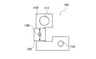
以下、本発明の好適な実施形態を図面に基づいて説明するのに先立って、シャント式電流センサの熱膨張差について詳細に説明する。図1は、従来のシャント抵抗式電流センサの一例を示す上面図である。図1に示すシャント抵抗式電流センサ101は、バッテリターミナルとして用いられるものであって、バスバ110と、回路基板120と、電圧検出IC130とを備えている。
Hereinafter, prior to describing a preferred embodiment of the present invention with reference to the drawings, a difference in thermal expansion of a shunt type current sensor will be described in detail. FIG. 1 is a top view showing an example of a conventional shunt resistance type current sensor. A shunt resistance type
バスバ110は、略平板形状の導電部材であって、例えば銅マンガン合金や銅ニッケル合金などにより構成されている。このバスバ110は、平板形状の鋼材からプレス成形により所望の形状に形成される。また、バスバ110はシャント抵抗の役割を果たし、被測定電流が流れるようになっている。
The
より詳細にバスバ110は、略L字状に形成され、L字のそれぞれの先端部に貫通孔111,112が形成されている。このうち一方の貫通孔111は、バッテリポスト用の孔として機能すると共に、他方の貫通孔112はワイヤーハーネス固定ネジ用の孔として機能する。
More specifically, the
回路基板120は、バスバ110の中間部に搭載され、バスバ110と接続ピン等により電気接続されている。電圧検出IC130は、バスバ110に流れる被測定電流の大きさを検出するために回路基板120に印加される電圧値を検出するものである。この電圧検出IC130による電圧値の検出により、バスバ110に生じる電圧降下が測定される。
The
ここで、バスバ110と回路基板120とは素材が異なっている。このため、熱膨張率が異なってしまう。一例を挙げると、20℃におけるバスバ110の線膨張率は16.5×10⁻⁶〔1/K〕であり、回路基板120の線膨張率は16.0×10−6〔1/K〕であるとすると、温度が上昇するとバスバ110の方が長くなってしまい、バスバ110と回路基板120との電気接続部である接続ピン等に応力が発生し、破損等してしまう可能性がある。
Here, the
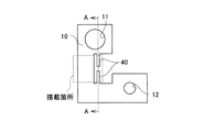
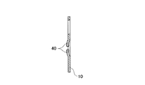
図2は、本発明の実施形態に係る本発明の実施形態に係るシャント抵抗式電流センサのバスバを示す上面図であり、図3は、本発明の実施形態に係る本発明の実施形態に係るシャント抵抗式電流センサのバスバを示すA−A断面図である。これらの図に示すシャント抵抗式電流センサ1は、接続端子部40を備えている。なお、バスバ10、回路基板20、及び電圧検出IC30は、図1に示したものと同様であるため、以下において重複する説明を省略する。
FIG. 2 is a top view showing a bus bar of the shunt resistance type current sensor according to the embodiment of the present invention according to the embodiment of the present invention, and FIG. 3 relates to the embodiment of the present invention according to the embodiment of the present invention. It is AA sectional drawing which shows the bus bar of a shunt resistance type current sensor. The shunt resistance type
接続端子部40は、バスバ10から延在されて形成され、バスバ10と同一部材にて形成されたものである。すなわち、バスバ10及び接続端子部40は、平板形状の鋼材からプレス成形により同時的に形成される。この接続端子部40は、バスバ10のうち回路基板20の搭載箇所の内方に向かって、バスバ10から延在されて形成されている。
The
また、本実施形態において接続端子部40は、対となって突き合わされて形成される共に、それぞれがバスバ10の平板部よりも立ち上げられて片持ち状となっている。接続端子部40は、その自由端側が回路基板20と半田付けにより電気接続される構成となっている。また、図2に示すように、接続端子部40それぞれは、幅方向の大きさが長さ方向の大きさよりも小さくされている。
Further, in the present embodiment, the connection
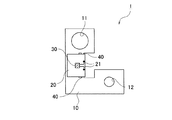
図4は、本実施形態に係るシャント抵抗式電流センサ1の上面図である。図4に示すように、回路基板20は回路パターン21が形成されている。電圧検出IC30は回路パターン21上に搭載されている。また、回路パターン21の端部は、上記した接続端子部40の自由端側に電気接続されている。これにより、電圧検出IC30は、回路基板20に印加される電圧値を検出し、電圧降下からバスバ10に流れる被測定電流の大きさを検出する。
FIG. 4 is a top view of the shunt resistance type
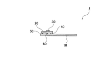
図5は、本実施形態に係るシャント抵抗式電流センサ1の側面図である。図5に示すように、シャント抵抗式電流センサ1は、スペーサ50と温度センサ(温度検出手段)60とをさらに備えている。
FIG. 5 is a side view of the shunt resistance type
スペーサ50は、バスバ10と回路基板20との間に介在される部材である。回路基板20は、接続端子部40がバスバ10の平板部よりも立ち上げられているため、バスバ10よりもやや高くなっている。このため、回路基板20の搭載箇所のうち接続端子部40の反対側領域にスペーサ50を介在させることで、高さ分を補っている。
The
温度センサ60は、回路基板20のうち電圧検出IC30の搭載面と反対側の面に設けられ、バスバ10と近接するように配置されている。このため、温度センサ60は、バスバ10近傍の温度を検出することとなる。
The
また、本実施形態において電圧検出IC30は、温度センサ60による検出結果に応じて、電圧補正を行う。すなわち、電圧検出IC30は、温度変化による抵抗変化の影響を受けて、誤った電流値を検出しないように温度結果に応じた電圧補正を行う。
In the present embodiment, the
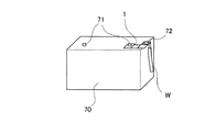
図6は、本実施形態に係るシャント抵抗式電流センサ1の使用状態図である。図6に示すように本実施形態に係るシャント抵抗式電流センサ1のバスバ10はバッテリターミナルとして用いられる。このため、バスバ10の貫通孔11はバッテリ70のバッテリポスト71に接続され、他方の貫通孔12にはワイヤーハーネス固定ネジ72を介してワイヤーハーネスWに接続される。
FIG. 6 is a use state diagram of the shunt resistance type
ここで、バスバ10がバッテリターミナルとして用いられる場合、バスバ10には銅合金などが使用され、温度変化が小さい他のシャント抵抗用の材料(例えばマンガニン)と比べると温度による抵抗変化が大きい。しかし、温度補正を行うため、バッテリターミナル用のシャント抵抗式電流センサ1として、より効果的な温度補正を行うことができる。
Here, when the
次に、本実施形態に係るシャント抵抗式電流センサ1の作用を説明する。まず、熱の影響によりバスバ10及び回路基板20の双方が熱膨張したとする。このとき、バスバ10と回路基板20との素材が異なることから、熱膨張率も異なることとなる。このため、膨張率差により応力が発生し、バスバ10と回路基板20とを電気的接続する接合部(すなわち半田部位)が破損して、電気的な接続がとれなくなってしまう可能性がある。
Next, the operation of the shunt resistance type
しかし、本実施形態に係るシャント抵抗式電流センサ1は接続端子部40を備えている。この接続端子部40はそれぞれがバスバ10の平板部よりも立ち上げられて片持ち状となっている。このため、接続端子部40の弾性力により応力が緩和されることとなる。これにより、接合部が応力により破損してしまう事態が抑制されることとなる。
However, the shunt resistance type
特に、接続端子部40は対となって突き合わされて形成されている。図7は、本実施形態に係るシャント抵抗式電流センサ1の作用を示すバスバ10の上面図である。接続端子部40を備えない構成の場合、シャント抵抗部の長さbに応じた応力が発生してしまう。これに対してそれぞれの接続端子部40の長さがcであるとすると、対となって突き合わされている間の距離d=b−2cに応じて応力が発生することとなる。すなわち、応力が発生する距離を短くすることで、応力自体を小さくすることができる。
In particular, the
よって、接合部の破損を防止することができる。また、接合部の破損を防止することができることから、回路基板20を可とう性が高く高価なフレキシブル回路基板等にする必要がなく、しかも、接続端子部40はバスバ10の平板部から立ち上げられて形成されているため、ピン状の接続部材も必要がない。
Therefore, breakage of the joint can be prevented. In addition, since the breakage of the joint portion can be prevented, the
さらに、接続端子部40は幅方向の大きさが長さ方向の大きさよりも小さくされていることから、接続端子部40が細くなり、より応力を緩和しやすくされており、一層接合部の破損を防止することができる。また、接続端子部40が細いことから半田付けにより回路基板20との電気接続を行う際に、熱が逃げ難く半田付けし易くすることができる。
Further, since the connecting
加えて、接続端子部40をバスバ10の平面部よりも高くしているため、バスバ10と回路基板20との接触も避けることとなる。
In addition, since the
このようにして、本実施形態に係るシャント抵抗式電流センサ1によれば、接続端子部40は、バスバ10のうち回路基板20の搭載箇所においてバスバ10から延在され、回路基板20と電気接続される。また、接続端子部40は、それぞれがバスバ10の平板部よりも立ち上げられて片持ち状となっている。このため、仮にバスバ10と回路基板20との熱膨張差により応力が発生したとしても、その応力が片持ち状に形成される接続端子部40の弾性力により緩和される。また、接続端子部40は、対となって突き合わされて形成されているため、応力が発生する距離を短くすることができ、応力を小さくすることができる。よって、熱膨張差による耐久性の問題を改善することができる。また、回路基板20を可とう性が高く高価なフレキシブル回路基板等にする必要がなく、しかも、接続端子部40はバスバ10の平板部から、その一部が立ち上げられて形成されているため、ピン状の接続部材も必要がない。よって、コスト面で改善を図ることができる。
Thus, according to the shunt resistance type
また、接続端子部40それぞれは、幅方向の大きさが長さ方向の大きさよりも小さくされているため、接続端子部40が細くなって撓みやすくなり、応力の緩和をし易くすることができる。また、接続端子部40が細いことから半田付けにより回路基板20との電気接続を行う際に、熱が逃げ難く半田付けし易くすることができる。
In addition, since each of the
また、バスバ10近傍の温度を検出する温度センサ60をさらに備え、電圧検出IC30は、温度センサ60による検出結果に応じて、電圧補正を行う。このため、温度の影響による抵抗変化によって誤った結果を得てしまうことを防止することができる。
In addition, a
また、バスバ10はバッテリターミナルである。ここでバッテリターミナルは銅合金などが使用され、温度変化が小さいシャント抵抗用の材料(例えばマンガニン)と比べると温度による抵抗変化が大きい。しかし、温度補正を行うため、バッテリターミナル用のシャント抵抗式電流センサ1として、より効果的な温度補正を行うことができる。
The
以上、実施形態に基づき本発明を説明したが、本発明は上記実施形態に限られるものではなく、本発明の趣旨を逸脱しない範囲で、変更を加えてもよい。 As described above, the present invention has been described based on the embodiment, but the present invention is not limited to the above embodiment, and may be modified without departing from the gist of the present invention.
例えば、本実施形態に係るシャント抵抗式電流センサ1において、接続端子部40は上記実施形態に係る形状に限定されるものではない。例えば本実施形態において接続端子部40は直線状であるが、これに限らず、曲線状等であってもよい。また、直線状や曲線状等の接続端子部40の一部に切り欠きが形成されていてもよい。また、接続端子部40の幅は一定でなくともよい。
For example, in the shunt resistance type
1…シャント抵抗式電流センサ
10…バスバ
11,12…貫通孔
20…回路基板
21…回路パターン
30…電圧検出IC(電圧検出手段)
40…接続端子部
50…スペーサ
60…温度センサ(温度検出手段)
DESCRIPTION OF
40 ...
Claims (4)
前記バスバ上に設置された回路基板と、
前記バスバから延在され、前記回路基板と電気接続される接続端子部と、
前記回路基板上に設置され、前記バスバに流れる被測定電流の大きさを検出するために前記接続端子部を介して回路基板に印加される電圧値を検出する電圧検出手段と、を備え、
前記接続端子部は、対となって突き合わされて形成される共に、それぞれが前記バスバの平板部よりも立ち上げられて片持ち状となっている
ことを特徴とするシャント抵抗式電流センサ。 A substantially flat bus bar;
A circuit board installed on the bus bar;
A connection terminal portion extending from the bus bar and electrically connected to the circuit board;
Voltage detecting means installed on the circuit board and detecting a voltage value applied to the circuit board via the connection terminal portion in order to detect the magnitude of the current to be measured flowing through the bus bar,
The connection terminal portions are formed to be abutted in pairs, and each of the connection terminal portions is raised from the flat plate portion of the bus bar and is cantilevered. Shunt resistance type current sensor.
ことを特徴とする請求項1に記載のシャント抵抗式電流センサ。 2. The shunt resistance type current sensor according to claim 1, wherein each of the connection terminal portions is smaller in size in the width direction than in the length direction.
前記電圧検出手段は、前記温度検出手段による検出結果に応じて、電圧補正を行う
ことを特徴とする請求項1又は請求項2のいずれかに記載のシャント抵抗式電流センサ。 A temperature detecting means for detecting a temperature in the vicinity of the bus bar;
The shunt resistance type current sensor according to claim 1, wherein the voltage detection unit performs voltage correction according to a detection result of the temperature detection unit.
ことを特徴とする請求項3に記載のシャント抵抗式電流センサ。 The shunt resistance type current sensor according to claim 3, wherein the bus bar is a battery terminal.
Priority Applications (4)
| Application Number | Priority Date | Filing Date | Title |
|---|---|---|---|
| JP2011083706A JP5926495B2 (en) | 2011-04-05 | 2011-04-05 | Shunt resistance type current sensor |
| PCT/JP2012/059947 WO2012137980A1 (en) | 2011-04-05 | 2012-04-05 | Shunt resistance type current sensor |
| EP12716689.0A EP2694985A1 (en) | 2011-04-05 | 2012-04-05 | Shunt resistance type current sensor |
| US14/032,423 US20140015515A1 (en) | 2011-04-05 | 2013-09-20 | Shunt Resistance Type Current Sensor |
Applications Claiming Priority (1)
| Application Number | Priority Date | Filing Date | Title |
|---|---|---|---|
| JP2011083706A JP5926495B2 (en) | 2011-04-05 | 2011-04-05 | Shunt resistance type current sensor |
Publications (2)
| Publication Number | Publication Date |
|---|---|
| JP2012220249A true JP2012220249A (en) | 2012-11-12 |
| JP5926495B2 JP5926495B2 (en) | 2016-05-25 |
Family
ID=46001687
Family Applications (1)
| Application Number | Title | Priority Date | Filing Date |
|---|---|---|---|
| JP2011083706A Expired - Fee Related JP5926495B2 (en) | 2011-04-05 | 2011-04-05 | Shunt resistance type current sensor |
Country Status (4)
| Country | Link |
|---|---|
| US (1) | US20140015515A1 (en) |
| EP (1) | EP2694985A1 (en) |
| JP (1) | JP5926495B2 (en) |
| WO (1) | WO2012137980A1 (en) |
Cited By (7)
| Publication number | Priority date | Publication date | Assignee | Title |
|---|---|---|---|---|
| WO2014115724A1 (en) * | 2013-01-23 | 2014-07-31 | 矢崎総業株式会社 | Shunt resistance-type current sensor |
| JP2015011844A (en) * | 2013-06-28 | 2015-01-19 | 三洋電機株式会社 | On-vehicle power supply device, vehicle having the power supply device, and bus bar |
| KR20150061881A (en) * | 2013-11-28 | 2015-06-05 | 현대모비스 주식회사 | Device for sensing battery of vehicel |
| KR20150125999A (en) * | 2013-03-05 | 2015-11-10 | 콘티넨탈 오토모티브 게엠베하 | Current sensor device with integrated clamping device and mass element |
| WO2016042732A1 (en) * | 2014-09-16 | 2016-03-24 | パナソニックIpマネジメント株式会社 | Battery sensor device |
| JP2017222195A (en) * | 2016-06-13 | 2017-12-21 | 日本精機株式会社 | Control device for vehicle horn |
| WO2020045915A1 (en) * | 2018-08-31 | 2020-03-05 | 주식회사 엘지화학 | System and method for correcting current value of shunt resistor |
Families Citing this family (10)
| Publication number | Priority date | Publication date | Assignee | Title |
|---|---|---|---|---|
| JP2014085245A (en) * | 2012-10-24 | 2014-05-12 | Yazaki Corp | Shunt resistor current sensor |
| US9831482B2 (en) | 2013-09-06 | 2017-11-28 | Johnson Controls Technology Company | Battery module lid system and method |
| DE102016014130B3 (en) * | 2016-11-25 | 2017-11-23 | Isabellenhütte Heusler Gmbh & Co. Kg | Current measuring device |
| CN109591601B (en) * | 2018-12-19 | 2020-11-17 | 安徽江淮汽车集团股份有限公司 | Self-diagnosis current divider circuit for vehicle |
| US11515585B2 (en) * | 2019-02-21 | 2022-11-29 | Datang Nxp Semiconductors Co., Ltd. | Accurate battery temperature measurement by compensating self heating |
| DE102019108541A1 (en) * | 2019-04-02 | 2020-10-08 | Eberspächer Controls Landau Gmbh & Co. Kg | Current measuring module |
| US11639967B2 (en) * | 2019-11-12 | 2023-05-02 | Samsung Sdi Co., Ltd. | Sensor system for a battery module |
| PL3823076T3 (en) * | 2019-11-12 | 2024-09-16 | Samsung Sdi Co., Ltd. | Sensor system for a battery module |
| WO2021104670A1 (en) * | 2019-11-27 | 2021-06-03 | Eaton Intelligent Power Limited | Busbar as current sensor |
| WO2023110715A2 (en) * | 2021-12-16 | 2023-06-22 | Vitesco Technologies GmbH | Current sensing system |
Citations (11)
| Publication number | Priority date | Publication date | Assignee | Title |
|---|---|---|---|---|
| JP2004221160A (en) * | 2003-01-10 | 2004-08-05 | Mitsubishi Electric Corp | Current detection resistor |
| JP2005017293A (en) * | 2003-06-26 | 2005-01-20 | Isabellenhuette Heusler Gmbh Kg | Resistance device, manufacturing method and measuring circuit |
| JP2005129379A (en) * | 2003-10-24 | 2005-05-19 | Auto Network Gijutsu Kenkyusho:Kk | Battery terminal |
| JP2005188931A (en) * | 2003-12-24 | 2005-07-14 | Auto Network Gijutsu Kenkyusho:Kk | Voltage drop type current measuring device |
| JP2008082957A (en) * | 2006-09-28 | 2008-04-10 | Denso Corp | Shunt resistor |
| JP2009040314A (en) * | 2007-08-10 | 2009-02-26 | Denso Corp | Vehicle system |
| JP2009063527A (en) * | 2007-09-10 | 2009-03-26 | Furukawa Electric Co Ltd:The | Current detector |
| JP2009177903A (en) * | 2008-01-23 | 2009-08-06 | Denso Corp | Vehicle system |
| WO2010121841A1 (en) * | 2009-07-01 | 2010-10-28 | Isabellenhütte Heusler Gmbh & Co. Kg | Electronic component and corresponding production method |
| JP2011003694A (en) * | 2009-06-18 | 2011-01-06 | Koa Corp | Shunt resistor, and method of manufacturing the same |
| JP2011047721A (en) * | 2009-08-25 | 2011-03-10 | Sanyo Electric Co Ltd | Shunt resistor, power supply device for vehicle equipped with the same, and the vehicle |
Family Cites Families (17)
| Publication number | Priority date | Publication date | Assignee | Title |
|---|---|---|---|---|
| JPH0483175A (en) * | 1990-07-25 | 1992-03-17 | Mitsubishi Electric Corp | Current detector |
| US6304062B1 (en) * | 1999-10-28 | 2001-10-16 | Powersmart, Inc. | Shunt resistance device for monitoring battery state of charge |
| US7319304B2 (en) * | 2003-07-25 | 2008-01-15 | Midtronics, Inc. | Shunt connection to a PCB of an energy management system employed in an automotive vehicle |
| DE20318266U1 (en) * | 2003-11-26 | 2004-02-19 | Hella Kg Hueck & Co. | Car battery current measurement unit has resistance connected to electronics by spring contacts |
| JP2005181119A (en) * | 2003-12-19 | 2005-07-07 | Auto Network Gijutsu Kenkyusho:Kk | Current sensor and circuit structure including the same |
| JP2005188972A (en) | 2003-12-24 | 2005-07-14 | Auto Network Gijutsu Kenkyusho:Kk | Voltage drop type current measuring device |
| JP2005188945A (en) * | 2003-12-24 | 2005-07-14 | Auto Network Gijutsu Kenkyusho:Kk | Voltage drop type current measuring device |
| JP2005188973A (en) | 2003-12-24 | 2005-07-14 | Auto Network Gijutsu Kenkyusho:Kk | Voltage drop type current measuring device |
| JP2005188935A (en) * | 2003-12-24 | 2005-07-14 | Auto Network Gijutsu Kenkyusho:Kk | Voltage drop type current measuring device |
| US7253602B2 (en) * | 2004-10-12 | 2007-08-07 | Eaton Corporation | Self-powered power bus sensor employing wireless communication |
| DE102004053648A1 (en) * | 2004-11-03 | 2006-05-04 | Leopold Kostal Gmbh & Co. Kg | Battery current sensor for a motor vehicle |
| FR2879751B1 (en) * | 2004-12-20 | 2007-02-23 | Johnson Controls Tech Co | DEVICE FOR MEASURING CIRCULATING CURRENT IN A CABLE |
| FR2884615B1 (en) * | 2005-04-13 | 2007-06-29 | Valeo Electronique Sys Liaison | DEVICE FOR MEASURING CURRENT, IN PARTICULAR A BATTERY |
| FR2903498B1 (en) * | 2006-07-07 | 2008-10-17 | Valeo Electronique Sys Liaison | BATTERY MONITORING SENSOR RESISTANT TO TEMPERATURE VARIATIONS. |
| JP2008039571A (en) * | 2006-08-04 | 2008-02-21 | Denso Corp | Current sensor |
| JP2011053003A (en) * | 2009-08-31 | 2011-03-17 | Denso Corp | Current detector |
| JP5424808B2 (en) | 2009-10-15 | 2014-02-26 | 株式会社アルバック | Print head and discharge device |
-
2011
- 2011-04-05 JP JP2011083706A patent/JP5926495B2/en not_active Expired - Fee Related
-
2012
- 2012-04-05 WO PCT/JP2012/059947 patent/WO2012137980A1/en not_active Ceased
- 2012-04-05 EP EP12716689.0A patent/EP2694985A1/en not_active Withdrawn
-
2013
- 2013-09-20 US US14/032,423 patent/US20140015515A1/en not_active Abandoned
Patent Citations (12)
| Publication number | Priority date | Publication date | Assignee | Title |
|---|---|---|---|---|
| JP2004221160A (en) * | 2003-01-10 | 2004-08-05 | Mitsubishi Electric Corp | Current detection resistor |
| JP2005017293A (en) * | 2003-06-26 | 2005-01-20 | Isabellenhuette Heusler Gmbh Kg | Resistance device, manufacturing method and measuring circuit |
| JP2005129379A (en) * | 2003-10-24 | 2005-05-19 | Auto Network Gijutsu Kenkyusho:Kk | Battery terminal |
| JP2005188931A (en) * | 2003-12-24 | 2005-07-14 | Auto Network Gijutsu Kenkyusho:Kk | Voltage drop type current measuring device |
| JP2008082957A (en) * | 2006-09-28 | 2008-04-10 | Denso Corp | Shunt resistor |
| JP2009040314A (en) * | 2007-08-10 | 2009-02-26 | Denso Corp | Vehicle system |
| JP2009063527A (en) * | 2007-09-10 | 2009-03-26 | Furukawa Electric Co Ltd:The | Current detector |
| JP2009177903A (en) * | 2008-01-23 | 2009-08-06 | Denso Corp | Vehicle system |
| JP2011003694A (en) * | 2009-06-18 | 2011-01-06 | Koa Corp | Shunt resistor, and method of manufacturing the same |
| WO2010121841A1 (en) * | 2009-07-01 | 2010-10-28 | Isabellenhütte Heusler Gmbh & Co. Kg | Electronic component and corresponding production method |
| JP2012531760A (en) * | 2009-07-01 | 2012-12-10 | イザベレンヒュッテ ホイスラー ゲー・エム・ベー・ハー ウント コンパニー コマンデイトゲゼルシャフト | Electronic component and manufacturing method thereof |
| JP2011047721A (en) * | 2009-08-25 | 2011-03-10 | Sanyo Electric Co Ltd | Shunt resistor, power supply device for vehicle equipped with the same, and the vehicle |
Cited By (17)
| Publication number | Priority date | Publication date | Assignee | Title |
|---|---|---|---|---|
| JP2014142226A (en) * | 2013-01-23 | 2014-08-07 | Yazaki Corp | Shunt resistance type current sensor |
| CN105324673A (en) * | 2013-01-23 | 2016-02-10 | 矢崎总业株式会社 | Shunt Resistive Current Sensor |
| WO2014115724A1 (en) * | 2013-01-23 | 2014-07-31 | 矢崎総業株式会社 | Shunt resistance-type current sensor |
| US9404949B2 (en) | 2013-01-23 | 2016-08-02 | Yazaki Corporation | Shunt resistance-type current sensor |
| KR102107268B1 (en) * | 2013-03-05 | 2020-05-06 | 콘티넨탈 오토모티브 게엠베하 | Current sensor device with integrated clamping device and mass element |
| US10677847B2 (en) | 2013-03-05 | 2020-06-09 | Continental Automotive Gmbh | Current sensor apparatus comprising an integrated clamping device and a grounding element |
| KR20150125999A (en) * | 2013-03-05 | 2015-11-10 | 콘티넨탈 오토모티브 게엠베하 | Current sensor device with integrated clamping device and mass element |
| JP2015011844A (en) * | 2013-06-28 | 2015-01-19 | 三洋電機株式会社 | On-vehicle power supply device, vehicle having the power supply device, and bus bar |
| KR102113765B1 (en) * | 2013-11-28 | 2020-05-21 | 현대모비스 주식회사 | Device for sensing battery of vehicel |
| KR20150061881A (en) * | 2013-11-28 | 2015-06-05 | 현대모비스 주식회사 | Device for sensing battery of vehicel |
| WO2016042732A1 (en) * | 2014-09-16 | 2016-03-24 | パナソニックIpマネジメント株式会社 | Battery sensor device |
| JP2017222195A (en) * | 2016-06-13 | 2017-12-21 | 日本精機株式会社 | Control device for vehicle horn |
| WO2020045915A1 (en) * | 2018-08-31 | 2020-03-05 | 주식회사 엘지화학 | System and method for correcting current value of shunt resistor |
| KR20200025784A (en) * | 2018-08-31 | 2020-03-10 | 주식회사 엘지화학 | System and method for correcting current value of shunt resistor |
| JP2021508817A (en) * | 2018-08-31 | 2021-03-11 | エルジー・ケム・リミテッド | Shunt resistor current value correction system and method |
| KR102234155B1 (en) | 2018-08-31 | 2021-03-30 | 주식회사 엘지화학 | System and method for correcting current value of shunt resistor |
| US11293948B2 (en) | 2018-08-31 | 2022-04-05 | Lg Energy Solution, Ltd. | System and method for correcting current value of shunt resistor |
Also Published As
| Publication number | Publication date |
|---|---|
| US20140015515A1 (en) | 2014-01-16 |
| WO2012137980A1 (en) | 2012-10-11 |
| JP5926495B2 (en) | 2016-05-25 |
| EP2694985A1 (en) | 2014-02-12 |
Similar Documents
| Publication | Publication Date | Title |
|---|---|---|
| JP5926495B2 (en) | Shunt resistance type current sensor | |
| JP5873315B2 (en) | Shunt resistance type current sensor | |
| US9404949B2 (en) | Shunt resistance-type current sensor | |
| CN115461826B (en) | Shunt resistor, method for manufacturing shunt resistor, and current detection device | |
| US20150108965A1 (en) | Shunt resistance type current sensor | |
| CN111693745A (en) | Passive current sensor with simplified geometry | |
| WO2013153874A1 (en) | Shunt resistance type current sensor | |
| US7937822B2 (en) | Method for connecting tab pattern and lead wire | |
| CN104662429A (en) | Shunt resistance-type current sensor | |
| JP2014085245A (en) | Shunt resistor current sensor | |
| JP2012177656A (en) | Shunt resistance type current sensor | |
| CN120322833A (en) | Shunt Resistors | |
| JP4278096B2 (en) | Temperature compensation device | |
| JP5918023B2 (en) | Shunt resistance type current sensor | |
| JP6082604B2 (en) | Shunt resistance type current sensor | |
| JP2015021816A (en) | Shunt resistance type current sensor | |
| JP2025181274A (en) | Current detection device | |
| JP2016038232A (en) | Resistance measuring electro-conductor, resistance measuring apparatus for electro-conductors, and electric current detecting apparatus | |
| JP2014062810A (en) | Shunt resistance type current sensor | |
| KR20150063988A (en) | Current sensing resistor |
Legal Events
| Date | Code | Title | Description |
|---|---|---|---|
| A621 | Written request for application examination |
Free format text: JAPANESE INTERMEDIATE CODE: A621 Effective date: 20140318 |
|
| A131 | Notification of reasons for refusal |
Free format text: JAPANESE INTERMEDIATE CODE: A131 Effective date: 20150324 |
|
| A521 | Request for written amendment filed |
Free format text: JAPANESE INTERMEDIATE CODE: A523 Effective date: 20150508 |
|
| A131 | Notification of reasons for refusal |
Free format text: JAPANESE INTERMEDIATE CODE: A131 Effective date: 20151020 |
|
| A521 | Request for written amendment filed |
Free format text: JAPANESE INTERMEDIATE CODE: A523 Effective date: 20151124 |
|
| TRDD | Decision of grant or rejection written | ||
| A01 | Written decision to grant a patent or to grant a registration (utility model) |
Free format text: JAPANESE INTERMEDIATE CODE: A01 Effective date: 20160419 |
|
| A61 | First payment of annual fees (during grant procedure) |
Free format text: JAPANESE INTERMEDIATE CODE: A61 Effective date: 20160422 |
|
| R150 | Certificate of patent or registration of utility model |
Ref document number: 5926495 Country of ref document: JP Free format text: JAPANESE INTERMEDIATE CODE: R150 |
|
| R250 | Receipt of annual fees |
Free format text: JAPANESE INTERMEDIATE CODE: R250 |
|
| R250 | Receipt of annual fees |
Free format text: JAPANESE INTERMEDIATE CODE: R250 |
|
| R250 | Receipt of annual fees |
Free format text: JAPANESE INTERMEDIATE CODE: R250 |
|
| R250 | Receipt of annual fees |
Free format text: JAPANESE INTERMEDIATE CODE: R250 |
|
| R250 | Receipt of annual fees |
Free format text: JAPANESE INTERMEDIATE CODE: R250 |
|
| S531 | Written request for registration of change of domicile |
Free format text: JAPANESE INTERMEDIATE CODE: R313531 |
|
| R350 | Written notification of registration of transfer |
Free format text: JAPANESE INTERMEDIATE CODE: R350 |
|
| R250 | Receipt of annual fees |
Free format text: JAPANESE INTERMEDIATE CODE: R250 |
|
| LAPS | Cancellation because of no payment of annual fees |