JP2012213633A - Target showing apparatus - Google Patents
Target showing apparatus Download PDFInfo
- Publication number
- JP2012213633A JP2012213633A JP2012083094A JP2012083094A JP2012213633A JP 2012213633 A JP2012213633 A JP 2012213633A JP 2012083094 A JP2012083094 A JP 2012083094A JP 2012083094 A JP2012083094 A JP 2012083094A JP 2012213633 A JP2012213633 A JP 2012213633A
- Authority
- JP
- Japan
- Prior art keywords
- target
- distance
- display
- subject
- eye
- Prior art date
- Legal status (The legal status is an assumption and is not a legal conclusion. Google has not performed a legal analysis and makes no representation as to the accuracy of the status listed.)
- Pending
Links
Images


Classifications
-
- A—HUMAN NECESSITIES
- A61—MEDICAL OR VETERINARY SCIENCE; HYGIENE
- A61B—DIAGNOSIS; SURGERY; IDENTIFICATION
- A61B3/00—Apparatus for testing the eyes; Instruments for examining the eyes
- A61B3/02—Subjective types, i.e. testing apparatus requiring the active assistance of the patient
- A61B3/028—Subjective types, i.e. testing apparatus requiring the active assistance of the patient for testing visual acuity; for determination of refraction, e.g. phoropters
- A61B3/032—Devices for presenting test symbols or characters, e.g. test chart projectors
-
- A—HUMAN NECESSITIES
- A61—MEDICAL OR VETERINARY SCIENCE; HYGIENE
- A61B—DIAGNOSIS; SURGERY; IDENTIFICATION
- A61B3/00—Apparatus for testing the eyes; Instruments for examining the eyes
- A61B3/02—Subjective types, i.e. testing apparatus requiring the active assistance of the patient
- A61B3/08—Subjective types, i.e. testing apparatus requiring the active assistance of the patient for testing binocular or stereoscopic vision, e.g. strabismus
-
- A—HUMAN NECESSITIES
- A61—MEDICAL OR VETERINARY SCIENCE; HYGIENE
- A61B—DIAGNOSIS; SURGERY; IDENTIFICATION
- A61B3/00—Apparatus for testing the eyes; Instruments for examining the eyes
- A61B3/10—Objective types, i.e. instruments for examining the eyes independent of the patients' perceptions or reactions
- A61B3/11—Objective types, i.e. instruments for examining the eyes independent of the patients' perceptions or reactions for measuring interpupillary distance or diameter of pupils
-
- G—PHYSICS
- G02—OPTICS
- G02B—OPTICAL ELEMENTS, SYSTEMS OR APPARATUS
- G02B30/00—Optical systems or apparatus for producing three-dimensional [3D] effects, e.g. stereoscopic images
- G02B30/20—Optical systems or apparatus for producing three-dimensional [3D] effects, e.g. stereoscopic images by providing first and second parallax images to an observer's left and right eyes
- G02B30/22—Optical systems or apparatus for producing three-dimensional [3D] effects, e.g. stereoscopic images by providing first and second parallax images to an observer's left and right eyes of the stereoscopic type
- G02B30/25—Optical systems or apparatus for producing three-dimensional [3D] effects, e.g. stereoscopic images by providing first and second parallax images to an observer's left and right eyes of the stereoscopic type using polarisation techniques
-
- H—ELECTRICITY
- H04—ELECTRIC COMMUNICATION TECHNIQUE
- H04N—PICTORIAL COMMUNICATION, e.g. TELEVISION
- H04N13/00—Stereoscopic video systems; Multi-view video systems; Details thereof
- H04N13/30—Image reproducers
- H04N13/332—Displays for viewing with the aid of special glasses or head-mounted displays [HMD]
- H04N13/337—Displays for viewing with the aid of special glasses or head-mounted displays [HMD] using polarisation multiplexing
-
- H—ELECTRICITY
- H04—ELECTRIC COMMUNICATION TECHNIQUE
- H04N—PICTORIAL COMMUNICATION, e.g. TELEVISION
- H04N13/00—Stereoscopic video systems; Multi-view video systems; Details thereof
- H04N13/30—Image reproducers
- H04N13/366—Image reproducers using viewer tracking
- H04N13/383—Image reproducers using viewer tracking for tracking with gaze detection, i.e. detecting the lines of sight of the viewer's eyes
Abstract
Description
本発明は、被検者の両眼視機能を検査するために被検者の左右眼に視標を呈示する視標呈示装置に関する。 The present invention relates to an optotype presenting apparatus that presents optotypes to the left and right eyes of a subject in order to examine the binocular vision function of the subject.
近年、液晶パネル等のディスプレイに視標を呈示(表示)することによって被検者眼の視力等を検査する視標呈示装置が知られている(例えば、特許文献1参照)。このような装置では、ディスプレイに表示する視標を変えることにより、様々な種類、形状、サイズ、等の視標を被検者眼に呈示できる。また、このような装置では、偏光等を利用して視標を被検者の左眼に呈示するための左眼用視標と、被検者の右眼に呈示するための右眼用視標に分離している。左眼用視標と右眼用視標のディスプレイ上での表示間隔(視標間隔)を持たせることによって、視標に視差を持たせている。これにより、被検者には、視標がディスプレイから浮き上がって(又は、沈み込んで)認識される。このようにして、立体視機能検査等の両眼視機能検査が行える。 2. Description of the Related Art In recent years, there has been known an optotype presenting apparatus that examines visual acuity and the like of a subject's eye by presenting (displaying) an optotype on a display such as a liquid crystal panel (for example, see Patent Document 1). In such an apparatus, by changing the target to be displayed on the display, targets of various types, shapes, sizes, etc. can be presented to the subject's eyes. Further, in such an apparatus, a left-eye target for presenting a target to the left eye of the subject using polarized light and a right-eye view for presenting to the right eye of the subject. The mark is separated. By providing a display interval (target interval) on the display of the left-eye target and the right-eye target, parallax is given to the target. As a result, the visual target is recognized by the subject as it floats (or sinks) from the display. Thus, a binocular visual function test such as a stereoscopic function test can be performed.
このような視差を持った視標を被検者が左右眼で見ると、視標は浮き上がって見える、又は沈み込んで見える。しかし、被検者の左右眼の瞳孔間距離が異なると、視標の浮き上がり量(距離)又は沈み込み量(距離)が異なって見える。すなわち、視差を持つ視標の融像位置は、瞳孔間距離の異なる被検者の左右眼には異なって見える。 When the subject sees the target with such parallax with the left and right eyes, the target appears to float or sink. However, when the distance between the pupils of the left and right eyes of the subject is different, the amount of lift (distance) or the amount of sink (distance) of the target appears to be different. That is, the fusion position of the target with parallax looks different to the left and right eyes of subjects having different interpupillary distances.
本発明は、上記従来技術の問題点に鑑み、被検者の瞳孔間距離に基づいて視差を持つ視標の融像位置が最適になるように調整することにより、より正確な検査が行える視標呈示装置を提供することを技術課題とする。 In view of the above-described problems of the prior art, the present invention can perform a more accurate examination by adjusting the fusion position of a target having parallax based on the distance between pupils of the subject. It is a technical problem to provide a sign presentation device.
本発明は、上記課題を解決するために、以下の構成を有することを特徴とする。
(1) 被検者の両眼視機能を検査するために被検者の左右眼に視標を呈示する視標呈示装置において、ディスプレイを有し、被検者の左右眼に対して視差を持った視標を表示する表示手段と、被検者の瞳孔間距離を入力する瞳孔間距離入力手段と、前記瞳孔間距離入力手段によって入力された前記瞳孔間距離に基づき、前記視標が基準位置から融像位置まで浮き上がって認識されるか、又は沈み込んで認識されるように、前記視標の視標間隔を調節して前記ディスプレイに表示する制御手段と、を有する、ことを特徴とする。
(2) (1)の視標呈示装置において、前記制御手段は、前記瞳孔間距離と前記基準位置から前記融像位置までの融像距離との積を被検者から前記融像位置までの距離で除して求めた視標間隔に基づき、前記視標の視標間隔を調節して前記ディスプレイに表示する、ことを特徴とする。
(3) (1)又は(2)の視標呈示装置において、前記ディスプレイは、カラー表示可能なディスプレイであって、1ピクセル内に複数種類の単色の各輝度を変更して表示可能な複数のサブピクセルを有するディスプレイであり、前記制御手段は、前記視標を表示するピクセルと境界を成すピクセルにおいて、前記視標間隔に基づき、1つのサブピクセルの輝度を制御する、ことを特徴とする。
(4) (3)の視標呈示装置において、前記制御手段は、前記視標を黒色又は白色の何れか1色で前記ディスプレイに表示する、ことを特徴とする。
(5) (4)の視標呈示装置において、前記制御手段は、前記ディスプレイに表示される前記視標の背景を前記視標の反対色で表示する、ことを特徴とする。
(6) 被検者の両眼視機能を検査するための視標を呈示する視標呈示装置は、視標を表示するためのディスプレイと、被検者の左右眼の瞳孔間距離を入力する瞳孔間距離入力部と、ディスプレイに立体視検査用の左眼用視標及び右眼用視標を表示させる制御部であって、被検者の両眼視で見える融像視標が、「基準位置から所定の融像位置までの融像距離」浮き上がって又は沈み込んで認識されるように、入力された瞳孔間距離に基づいて左眼用視標と右眼用視標との左右方向の視標間隔を取得し、取得した視標間隔に基づいてディスプレイに左眼用視標及び右眼用視標を表示させる制御部と、を備える、ことを特徴とする。
(7) (6)の視標呈示装置において、制御部は、瞳孔間距離と融像距離との積を、被検者から融像位置までの距離で除して視標間隔を求める、ことを特徴とする。
(8) (6)又は(7)の視標呈示装置において、制御部は、ディスプレイが有する1ピクセルの整数倍より細かな距離として,視標間隔を被検者に認識させるために、右眼用視標及び左眼視標の少なくとも一方の境界であって、左右方向の境界が位置するピクセルの輝度を取得し、取得した視標間隔に基づいて変える、、ことを特徴とする。
(9) (6)又は(7)の視標呈示装置において、ディスプレイは、1ピクセル毎に色の異なる複数のサブピクセルが左右方向に並べられたカラーディスプレイであり、制御部は、1ピクセルの整数倍より細かな距離として視標間隔を被検者に認識させるために、右眼用視標及び左眼用視標の少なくとも一方の境界であって、左右方向の境界が位置するピクセル内の各サブピクセルの輝度を、取得した視標間隔に基づき、視標側から背景側に順に変化させる、ことを特徴とする。
(10) (9)の視標呈示装置において、制御部は、視標を黒色又は白色の何れか1色でディスプレイに表示する、ことを特徴とする。
(11) (10)の視標呈示装置において、制御部は、ディスプレイに表示される視標の背景を視標の反対色で表示する、ことを特徴とする。
(12) (6)〜(11)の何れかの視標呈示装置は、基準位置から所定の融像位置までの融像距離を入力する融像距離入力部を備えている、ことを特徴とする。
(13) (6)〜(12)の何れかの視標呈示装置において、左眼用視標及び右眼用視標は、同一形状、同一サイズ及び同一色である、ことを特徴とする。
In order to solve the above-mentioned problems, the present invention has the following configuration.
(1) An optotype presenting apparatus that presents an optotype to the left and right eyes of the subject in order to examine the binocular vision function of the subject, and has a display, and provides parallax to the left and right eyes of the subject. Based on the interpupillary distance input by the display means for displaying the target index, the interpupillary distance input means for inputting the interpupillary distance of the subject, and the interpupillary distance input means, Control means for adjusting the target interval of the target and displaying it on the display so that it can be recognized by rising from the position to the fusion position or being recognized by sinking. To do.
(2) In the optotype presenting apparatus according to (1), the control means calculates a product of the interpupillary distance and the fusion distance from the reference position to the fusion position from the subject to the fusion position. Based on the target interval determined by dividing by the distance, the target interval of the target is adjusted and displayed on the display.
(3) In the visual target presenting device according to (1) or (2), the display is a display capable of color display, and a plurality of types of display that can be displayed by changing each luminance of a plurality of types of single colors within one pixel. In the display having sub-pixels, the control means controls the luminance of one sub-pixel based on the target interval in a pixel that forms a boundary with a pixel that displays the target.
(4) In the optotype presenting apparatus according to (3), the control means displays the optotype on the display in one color of black or white.
(5) In the optotype presenting apparatus according to (4), the control means displays a background of the optotype displayed on the display in a color opposite to the optotype.
(6) An optotype presenting apparatus for presenting an optotype for inspecting the binocular vision function of a subject inputs a display for displaying the optotype and a distance between pupils of left and right eyes of the subject. An interpupillary distance input unit and a control unit that displays a left-eye target and a right-eye target for stereoscopic examination on a display, and a fusion target that can be viewed with binocular vision of the subject is `` Left and right eye targets and right eye targets based on the input interpupillary distance so that they can be recognized by rising or sinking the fusion distance from the reference position to the predetermined fusion position. And a control unit that displays a left-eye target and a right-eye target on a display based on the acquired target interval.
(7) In the target presentation device of (6), the control unit obtains the target interval by dividing the product of the interpupillary distance and the fusion distance by the distance from the subject to the fusion position. It is characterized by.
(8) In the optotype presenting apparatus according to (6) or (7), the control unit uses the right eye to recognize the optotype interval as a distance finer than an integer multiple of one pixel of the display. The brightness of a pixel that is at least one boundary of the visual target and the left eye visual target and in which the horizontal boundary is located is acquired, and is changed based on the acquired target interval.
(9) In the optotype presenting apparatus according to (6) or (7), the display is a color display in which a plurality of subpixels having different colors are arranged in the left-right direction for each pixel, and the control unit In order to make the subject recognize the target interval as a distance finer than an integral multiple, at least one boundary of the right-eye target and the left-eye target within the pixel where the left-right boundary is located The luminance of each sub-pixel is changed in order from the target side to the background side based on the acquired target interval.
(10) In the target presentation device according to (9), the control unit displays the target on the display in one of black or white.
(11) In the target presentation device of (10), the control unit displays a background of the target displayed on the display in a color opposite to the target.
(12) The target presentation apparatus according to any one of (6) to (11) includes a fusion distance input unit that inputs a fusion distance from a reference position to a predetermined fusion position. To do.
(13) In the target presentation device according to any one of (6) to (12), the left-eye target and the right-eye target have the same shape, the same size, and the same color.
本発明によれば、被検者の瞳孔間距離に基づいて視差を持つ視標の融像位置が最適になるように調整することにより、より正確な検査が行える。 According to the present invention, a more accurate examination can be performed by adjusting the fusion position of the target having parallax based on the distance between the pupils of the subject.
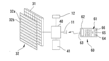
以下、本発明の実施形態を図面に基づいて説明する。図1は、本実施形態の視標呈示装置の概略外観図である。視標呈示装置100の筐体10の前面には、表示手段である視標呈示部30が設けられている。視標呈示部30は、被検者との距離が6m等の遠方距離の位置に置かれた場合にも所定サイズの視力検査用視標70a(例えば、VA(Visual Acuity)2.0のランドルト環視標)等の視標が呈示(表示)可能な大きさを持つ画面を備えており、内部にはカラー液晶ディスプレイ31が配置されている(図2参照)。ディスプレイ31には、例えば、解像度SXGAの19インチ、17インチ、等のものを用いることができる。なお、筐体10は、壁に掛けて使用できる薄型とされている。
Hereinafter, embodiments of the present invention will be described with reference to the drawings. FIG. 1 is a schematic external view of the optotype presenting apparatus according to the present embodiment. On the front surface of the
筐体10の前面の下方には、操作手段(操作部)であるリモートコントローラ(以下、リモコン)60からの赤外通信信号を受信する受信部11が設けられている。また、筐体10の下部には、装置100の設置距離(被検者(被検者眼)から視標呈示部30までの距離)の設定(入力)等の各種設定(入力)を行うための設定手段(設定部(入力部))であるファンクションキー12が設けられている。
A receiving
リモコン60は、視標呈示部30(ディスプレイ31)に呈示(表示)される視標を選択するための選択手段(選択部(セレクタ))である複数の視標選択キー(ボタン)61と、選択された視標等の情報を表示する表示手段(表示部)である液晶ディスプレイ62と、赤外通信信号を送信する送信部63と、を備えている。また、リモコン60は、装置100の設置距離を入力するための入力手段(入力部)である設置距離入力キー(ボタン)64と、被検者の瞳孔間距離(PD(pupillary distance))を入力するための入力手段(入力部)である瞳孔間距離入力キー(ボタン)65と、視差を持つ視標の融像距離を入力するための入力手段(入力部)である融像距離入力キー(ボタン)66と、を備えている。なお、被検者に呈示される立体視検査用の視標は、被検者の左眼に呈示するための左眼用視標と、被検者の右眼に呈示するための右眼用視標とを有している。立体視検査用の左眼用視標と右用視標は、左右方向におて所定の視標間距離離れて呈示される。被検者の左眼に左眼用視標が見え、被検者の右眼に右眼用視標が見え、被検者がそれぞれの視標を融像(一つの像として見る)すると、視標は浮き上がって(又は沈み込んで)認識される。なお、融像距離とは、基準面(基準位置、ここでは、ディスプレイ31の表示面)から浮き上がって見える、又は沈み込んで見える視標までの距離とする。なお、融像距離は、被検者から浮き上がって見える、又は沈み込んで見える視標までの距離としてもよい。
The
図2は、視標呈示部30の概略構成図と装置100の制御系の概略ブロック図とである。視標呈示部30は、カラーディスプレイであるカラー液晶ディスプレイ31と、ディスプレイ31の前面に配置(貼付)されたシート状の偏光光学部材32と、を備えている。ディスプレイ31には、1ピクセルで様々な色が表示できるように、赤色、青色及び緑色(光の三原色)のサブピクセルが1ピクセル内に左右方向(ここでは、水平方向と一致する)に並べられている。偏光光学部材32は、少なくともディスプレイ31の視標呈示(表示)領域をカバーする大きさを持っている。
FIG. 2 is a schematic configuration diagram of the
ディスプレイ31と受信部11とファンクションキー12とは、装置100の制御手段(制御部)である制御ユニット40に接続されている。また、制御ユニット40には、様々な視標のデータを記憶する記憶手段(記憶部)であるメモリ41が接続されており、また、リモコン60からの指令信号を解読するデコーダ回路等を備えている。制御ユニット40は、リモコン60からの視標切換えの指令信号等の入力により、ディスプレイ31の各ピクセルの表示を制御する。また、制御ユニット40は、ディスプレイ31に表示させた視標の境界(視標と背景との境界)において、ピクセル毎にサブピクセル処理することにより、視標の表示(呈示)位置が移動したように被検者に見せる(認識させる)(詳しくは後述する)。
The
偏光光学部材32について説明する。ディスプレイ31からは、所定の方向(垂直方向,水平方向又は斜め45度方向)の偏光軸を持つ直線偏光の光が出射される。本実施形態では、垂直方向の偏光軸を持つ直線偏光の光が出射される。偏光光学部材32は、ディスプレイ31が持つ1ピクセルの所定倍の大きさに対応して左右方向に延びるライン状で且つ縦方向(鉛直方向)に交互に配置された光学領域32aと光学領域32bとを備えている。光学領域32aと光学領域32bとは、ディスプレイ31からの直線偏光の光を通過させるときに、互いに直交する偏光軸を持つ直線偏光の光に変換する。本実施形態では、偏光光学部材32として、位相差機能を持つ1/2波長板と同等の機能を持つものが使用されている。1/2波長板は、周知のように、入射光の偏光軸が1/2波長板の高速軸(又は低速軸)に対して角度θで入射したときに、その振動方向を2×θ回転させる。すなわち、1/2波長板は、入射光の偏光方向に対して高速軸(又は低速軸)である光学的主軸方向を傾斜させることにより、入射光の偏光軸方向(振動方向)を回転させる機能を持つものであり、入射光の光量をそのまま維持できる特性を持つものである。
The polarizing
立体視検査等の両眼視機能検査では、互いに直交する偏光軸を持つ偏光フィルタ91Lと偏光フィルタ91Rとを備える偏光眼鏡90を被検者が装用し、被検者の左眼の前に偏光フィルタ91Lが配置され、被検者の右眼の前に偏光フィルタ91Rが配置される。本実施形態の偏光フィルタ91Lは45度方向に偏光軸を持っており、偏光フィルタ91Rは135度方向に偏光軸を持っている。また、被検者が偏光眼鏡90を装用する代わりに、左右の検査窓に球面レンズ、柱面レンズ、補助レンズ、等が切換え配置される自覚式屈折力検査装置(以下、ホロプタ)200が使用されてもよい。この場合には、ホロプタ200は、互いに直交する偏光軸を持つ偏光フィルタ201L(45度方向に偏光軸を持つ)と偏光フィルタ201R(135度方向に偏光軸を持つ)とを備え、被検者の左眼の前に配置される左検査窓に偏光フィルタ201Lが配置され、被検者の右眼の前に配置される右検査窓に偏光フィルタ201Rが配置される。
In a binocular function test such as a stereoscopic test, a subject wears
一方、光学領域32aは左眼用の光学領域であり、本実施形態では、その光学的主軸方向は、偏光眼鏡90又はホロプタ200が備える左眼用の偏光フィルタ91L又は201Lの偏光方向である45度方向と一致した偏光方向の光にディスプレイ31からの光を変換するように配置されている。また、光学領域32bは右眼用の光学領域であり、本実施形態では、その光学的主軸方向は、偏光眼鏡90又はホロプタ200が備える右眼用の偏光フィルタ91R又は201Rの偏光方向である135度方向と一致した偏光方向の光にディスプレイ31からの光を変換するように配置されている。このため、被検者が左右眼の前に配置された偏光フィルタ91L及び91R、又は偏光フィルタ201L及び201Rを通して視標呈示部30を見ると、左眼には偏光フィルタ91L又は201Lを透過可能な光学領域32aからの光のみが視認され、光学領域32bからの光は偏光フィルタ91R又は201Rで遮断されることによって視認されない。逆に、右眼には偏光フィルタ91R又は201Rを透過可能な光学領域32bからの光のみが視認され、光学領域32aからの光は偏光フィルタ91L又は201Lで遮断されることによって視認されない。このようにして、被検者の左右眼に入射する光を分離でき、被検者の左右眼にそれぞれ異なる視標を呈示できる。すなわち、視差を持つ視標を被検者の左右眼に呈示できる。
On the other hand, the
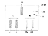
次に、ディスプレイ31に呈示(表示)される三桿検査用視標について説明する。図3は、本実施形態の三桿検査用視標(画像)を正面から見た状態を示す図である。図4は、三桿検査用視標と被検者の瞳孔間距離との関係を説明する図である。図5は、サブピクセル処理について説明する図である。図6は、三桿検査用視標の見え方を模式的に示した図である。
Next, the three eye test target presented (displayed) on the
なお、本実施形態では、検査距離(=装置100の設置距離)DEを2.5mとしており、検査の基準となる視標からの浮き上がり量又は沈み込み量を2cmとしている。また、装置の設置距離は、2.5mから6.0mまで50cm刻みで設定可能となっている。 In this embodiment, the inspection distance (= installation distance of the apparatus 100) DE is 2.5 m, and the amount of lifting or sinking from the target that is the reference for inspection is 2 cm. Further, the installation distance of the apparatus can be set in increments of 50 cm from 2.5 m to 6.0 m.
視標(画像)70には、簡易的な三桿検査をするために、3種類の視標が含まれている。本実施形態の視標70は、三桿計での三桿検査を模した検査が行えるように、桿(棒)状の視標とされている。視標70は、被検者から検査距離DE離れた位置に見える(認識される)、検査の基準となる視標(第1視標)71と、基準視標71から融像距離FD分浮き出がって被検者に見える(認識される)視標(第2視標)72と、基準視標71から融像距離FD分沈み込んで被検者に見える(認識される)視標(第2視標)73と、を含んでいる。視標70の背景70aは白色であり、視標71、72及び73は、すべて同一色の黒色である。また、視標71、72及び73は、同形状、同サイズとされる。
The visual target (image) 70 includes three types of visual targets in order to perform a simple three eye test. The
視標71は、左右眼に同じ位置に認識されるように、1つの視標である。視標72は、左眼用視標72Lと右眼用視標72Rとを含む。視標72Lと視標72Rとは、間隔W2隔てられている。被検者の両眼視によって、視標72が融像して見えるように、視標72L及び72Rは、同形状、同サイズ及び同色とされる。視標73は、左眼用視標73Lと右眼用視標73Rとを含む。視標73Lと視標73Rとは、間隔W3隔てられている。被検者の両眼視によって、視標73が融像して見えるように、視標73L及び73Rは、同形状、同サイズ及び同色とされる。間隔W2は、検査距離DEと被検者の瞳孔間距離PDとに基づいて定められており、何れの瞳孔間距離PDであっても視標72は視標呈示部30の画面から一定距離(融像距離FD)分浮き上がって見える(認識される)ような間隔とされている。同様に、間隔W3は、検査距離DEと被検者の瞳孔間距離PDとに基づいて定められており、何れの瞳孔間距離PDであっても視標73は視標呈示部30の画面から一定距離(融像距離FD)分沈み込んで見える(認識される)ような間隔とされている。
The
本実施形態の装置での三桿検査は、三桿計での三桿検査を模した検査が行えるように、検査距離DEが2.5mに設定されており、被検者の瞳孔間距離PDに拘らず、視標72の浮き上がり量と視標73の沈み込み量とが共に2cmに設定されている。検査距離DEは、三桿計での三桿検査において被検者眼から固定配置された左右2つの桿までの距離と等しくなっている。融像距離FD(浮き上がり量及び沈み込み量)は、三桿計での三桿検査において被検者眼が深視力を持つと判定される条件に基づいて設定されている。すなわち、三桿計での三桿検査においては、被検者の操作によって移動される中央の桿が左右の桿から前後2cm以内に位置されることにより、三桿検査の合格が判定される。このため、融像距離FDは、この条件に合うようになっている。
In the third eye examination with the apparatus of this embodiment, the examination distance DE is set to 2.5 m so that the examination imitating the third eye examination with a trigeometer can be performed, and the interpupillary distance PD of the subject. Regardless of this, both the lifting amount of the
また、本実施形態では、視標70は、ベクターデータとしてメモリ41に記憶されている。制御ユニット40は、検査距離DE、瞳孔間距離PD及び融像距離FDに基づいて視標間隔(視標間距離)W2及びW3を求め(取得し)、求められた視標間隔W2及びW3に基づいて視標70を生成し、視標呈示部30に呈示する(ディスプレイ31に表示する)。
In the present embodiment, the
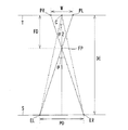
次に、瞳孔間距離PDと融像距離FDとの関係を説明する。ここでは、浮き上がって見せる場合を例に挙げて説明する。図4では、各位置を点として示している。左眼ELと右眼ERとが並ぶ面Sは、検査距離DEを隔てて、左眼用視標PLと右眼用視標PRとが並ぶ面T(視標呈示部30の画面と一致)と対向している。左眼ELと視標PLとを結んだ線分と右眼ERと視標PLとを結んだ線分との交点に、視標の融像位置FPができる。面Tから融像位置FPまでの距離が融像距離FDとなる。左眼ELと右眼ERとの間隔を瞳孔間距離PDとし、視標PLと視標PRとの間隔を視標間隔Wとする。 Next, the relationship between the inter-pupil distance PD and the fusion distance FD will be described. Here, the case where it floats up and shows is mentioned as an example, and is demonstrated. In FIG. 4, each position is shown as a point. A surface S in which the left eye EL and the right eye ER are arranged is a surface T in which the left eye target PL and the right eye target PR are arranged at the inspection distance DE (matches the screen of the target presenting unit 30). Is facing. The fusion position FP of the visual target is formed at the intersection of the line segment connecting the left eye EL and the target PL and the line segment connecting the right eye ER and the target PL. The distance from the surface T to the fusion position FP is the fusion distance FD. An interval between the left eye EL and the right eye ER is an interpupillary distance PD, and an interval between the target PL and the target PR is a target interval W.
ここで、立体視検査における視差は、左眼ELと融像位置FPとを結んだ線分と右眼ERと融像位置FPとを結んだ線分とが成す角度θ1と、左眼ELと面Tの中心Cとを結んだ線分と右眼ERと中心Cとを結んだ線分とが成す角度θ2と、の差分となる。従って、検査距離DEと視標間隔Wとがそれぞれ一定であれば、視差は、瞳孔間距離PDに拘らず一定となる。しかし、融像距離FDは、瞳孔間距離PDに応じて変化する。具体的に、瞳孔間距離PDと融像距離FDとの関係を示すと、図4における三角形の関係から、以下の式1のようになる。なお、DE−FDは、被検者から融像位置FPまでの距離になる。 Here, the parallax in the stereoscopic examination is the angle θ1 formed by the line segment connecting the left eye EL and the fusion position FP and the line segment connecting the right eye ER and the fusion position FP, and the left eye EL. This is the difference between the angle θ2 formed by the line segment connecting the center C of the surface T and the line segment connecting the right eye ER and the center C. Therefore, if the examination distance DE and the target interval W are constant, the parallax is constant regardless of the inter-pupil distance PD. However, the fusion distance FD changes according to the inter-pupil distance PD. Specifically, the relationship between the interpupillary distance PD and the fusion distance FD is expressed by the following formula 1 from the triangular relationship in FIG. The DE-FD is a distance from the subject to the fusion position FP.
PD:W=DE−FD:FD (式1)
式1を、融像距離FDについて解くと、以下の式2のようになる。
PD: W = DE-FD: FD (Formula 1)
Solving Equation 1 for the fusion distance FD gives
FD=W・DE/(PD+W) (式2)
式2から、融像距離FDは、瞳孔間距離PDに依存することがわかる。また、融像距離FDは、視標間隔Wに依存することがわかる。式1を視標間隔Wについて解くと、以下の式3のようになる。
FD = W · DE / (PD + W) (Formula 2)
From
W=PD・FD/(DE−FD) (式3)
本実施形態では、融像距離FDを一定(2cm)とし、瞳孔間距離PDを変数とし、融像距離FDを一定とできるような視標間隔Wを求め、視標を生成する。
W = PD · FD / (DE−FD) (Formula 3)
In this embodiment, the fusion distance FD is constant (2 cm), the interpupillary distance PD is a variable, and a visual target interval W that can make the fusion distance FD constant is obtained to generate a visual target.
次に、視標間隔Wの調節幅を説明する。例えば、瞳孔間距離PDを1mmステップで入力して、何れの場合にも融像距離FDを2cmとする場合を例に挙げ、瞳孔間距離PDを60mmの場合と59mmの場合とで視標間隔Wの差を説明する。式3において、FD=20(mm)、DE=2500(mm)とすると、PD=60(mm)の場合は、W=0.484(mm)となり、PD=59(mm)の場合は、W=0.476(mm)となる。瞳孔間距離PDと視標間隔Wとの関係は、線形であるため、瞳孔間距離PDが1mm変化すれば、視標間隔Wは0.008mm程度変化させればよいこととなる。従って、検査距離DEが2.5mの場合の使用において、視標呈示部30(ディスプレイ30)の解像度が0.008mmであれば、瞳孔間距離PDが1mmステップで変化する場合に対応した視標を呈示することができる。 Next, the adjustment range of the target interval W will be described. For example, when the inter-pupil distance PD is input in 1 mm steps and the fusion distance FD is set to 2 cm in any case, the target interval is set between the cases where the inter-pupil distance PD is 60 mm and 59 mm. The difference in W will be described. In Equation 3, when FD = 20 (mm) and DE = 2500 (mm), when PD = 60 (mm), W = 0.484 (mm), and when PD = 59 (mm), W = 0.476 (mm). Since the relationship between the inter-pupil distance PD and the target interval W is linear, if the inter-pupil distance PD changes by 1 mm, the target interval W may be changed by about 0.008 mm. Accordingly, in the case where the examination distance DE is 2.5 m, if the resolution of the target presentation unit 30 (display 30) is 0.008 mm, the target corresponding to the case where the inter-pupil distance PD changes in 1 mm steps. Can be presented.
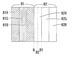
次に、視標間隔Wの調節表示について説明する。図5は、視標72又は73において、左右眼の何れかに呈示する場合での境界周辺の2ピクセルを模式的に示したものである。各ピクセルには、色の異なる複数のサブピクセルを左右方向に並べられている。各ピクセル81及び82は、3つのサブピクセルを備える。サブピクセルとしては、赤色を表示する(赤色発光する)ためのサブピクセル81R及び82Rと、緑色を表示する(緑色発光する)ためのサブピクセル81G及び82Gと、青色を表示する(青色発光する)ためのサブピクセル81B及び82Bと、である。各サブピクセルは、各単色を256階調の輝度で独立して表示(発光)可能であり、輝度としては、0〜255までとする。すべてのサブピクセルの輝度が0であれば、ピクセルは黒色として見え(認識され)、すべてのサブピクセルの輝度が255であれば、ピクセルは白色として見える(認識される)。
Next, adjustment display of the target interval W will be described. FIG. 5 schematically shows two pixels around the boundary when the
ピクセル81とピクセル82との間には、境界Bがある。ピクセル81は、すべてのサブピクセル(81R、81G、81B)が輝度0であり、黒色として見える(認識される)。一方、ピクセル82は、すべてのサブピクセル(82R、82G、82B)が輝度255であり、白色として見える(認識される)。この場合、視標72又は73の輪郭の位置は、境界Bにあるように見える。
There is a boundary B between the
この状態において、サブピクセル82Rを輝度0にすると、ビクセル82は、シアン色として見える(認識される)。しかし、ピクセル81の隣のサブピクセル82Rは、黒色として見える(認識される)。このため、被検者にとって、視標72又は73の輪郭の位置は、境界Bを越えてサブピクセル82Rとサブピクセル82Gの境界B1にあるように見える(認識される)。このとき、ピクセル82は、シアン色に見えるものの、視標72又は73の周辺では黒色と白色とで表示されている(見えている)ことと、ピクセル82が1ピクセル分しかないことと、から、被検者にシアン色が見える(認識される)ことは少ない。同様に、サブピクセル82G又は82Bの輝度を0にすることによっても、視標72又は73の輪郭の位置を変更して被検者に見せる(認識させる)ことができる。
In this state, when the luminance of the sub-pixel 82R is 0, the
このようにして、1ピクセル内の3つのサブピクセルの輝度を変えることにより、視標72又は73の輪郭の位置(視標間隔)を1ピクセルよりも下のオーダーで変更できる。制御ユニット40は、視標間隔がディスプレイ31が有するピクセルの整数倍より細かな距離となる場合に、サブピクセル処理を行う。制御ユニット40は、左眼用視標及び左眼視標の少なくとも一方に対してサブピクセル処理を行う。例えば、一方の視標の境界を処理する場合、一方の視標の左右方向の輪郭(両側の輪郭)に対して、それぞれ処理する。制御ユニット40は、演算により視標の境界のピクセルの輝度(サブピクセルの輝度)を取得し、ディスプレイ31の表示制御を行う。これによって、制御ユニット40が求めた視標間隔(被検者のPDに対応する)で、被検者に立体検査用視標が呈示可能となる。
In this way, by changing the luminance of the three sub-pixels in one pixel, the position of the contour of the
以上の説明では、サブピクセルの輝度を0又は255としたが、サブピクセルの輝度を段階的に変更することによっても、視標72又は73の輪郭の位置を変更できる。例えば、サブピクセルの256階調の輝度を8等分する。輝度は、1ステップ当り32の数値で変更することとなる。例えば、サブピクセル82Rの輝度を127とすると、境界Bと境界B1との間の発光量が半分になり、サブピクセル82Rとサブピクセル82Gとの間で発光量に濃淡差が生じる。これにより、被検者には、境界Bと境界B1との間の境界B2に視標72又は73の輪郭の位置があるように見える(認識される)。すなわち、サブピクセル82Rの輝度(サブピクセル間の濃淡差)に応じて、視標72の輪郭の位置を境界Bから境界B1内で移動させて認識させることができる。これは、サブピクセル82G及び82Bにおいても同様である。また、ピクセル内のサブピクセルは、視標側から背景側に順(この場合は、82R、82G、82Bの順)に輝度を変化させることで、境界の位置(輪郭)を視標側から背景側へと移動させる(移動したように被検者に認識させる)ことができる。
In the above description, the luminance of the subpixel is set to 0 or 255. However, the position of the contour of the
このようにして、視標の輪郭の位置を1つのサブピクセル内で変更させて被検者に認識させることができる。上記のサブピクセル処理をするためには、背景70aと視標72又は73とのコントラスをできるだけ高くすると共に、視標72又は73の境界の色の影響を軽減するために、視標72又は73の色は白色と黒色との一方から選択することが好ましく、背景70aの色も白色と黒色との他方から選択することが好ましい。
In this way, the position of the outline of the visual target can be changed within one sub-pixel and recognized by the subject. In order to perform the above subpixel processing, the contrast between the
上記の例では、1つのサブピクセルの輝度を8等分としたため、1ピクセル(ピクセル82)では、視標72又は73の輪郭の位置を、8×3の24通りで調節することができる。従って、1ピクセルが0.19mm程度のディスプレイを視標呈示部30に用いる場合、視標72又は73の輪郭の位置を、0.008mm程度のステップで調節することができる。
In the above example, since the luminance of one subpixel is divided into eight equal parts, the position of the outline of the
以上のような構成を有する視標呈示装置100での三桿検査における動作について説明する。検者は、検査の前に装置100の設定を行い、また、検査距離DE(被検者の検査位置)と融像距離FDとを決定し、リモコン60のキー64及び66又はファンクションキー12を操作して入力する。する。また、被検者の瞳孔間距離PDをリモコン60のキー65又はファンクションキー12を操作して入力する。瞳孔間距離PDは、瞳孔間距離計等で予め入手しておく。制御ユニット40は、リモコン60又はファンクションキー12からの指令信号に基づいて、検査距離DE、融像距離FD及び瞳孔間距離PDをメモリ41に記憶させる。
An operation in the three eye test with the
次に、検者は、偏光眼鏡90を装用した被検者又は左右眼前にホロプタ200を配置した被検者を検査位置に位置させ、キー61を操作して三桿検査用視標70を呈示させる。制御ユニット40は、リモコン60からの指令信号に基づいて、メモリ41に記憶された検査距離DE、融像距離FD及び瞳孔間距離PDを呼び出し(読み出し)、視標70の融像距離(浮き上がり量及び沈み込み量)が設定(入力)された融像距離FDになるように、検査距離DE及び瞳孔間距離PDに基づいて視標72の視標間隔W2と視標73の視標間隔W3とを求める。制御ユニット40は、求めた視標間隔W2及びW3に基づいて、視標70(視標71、72及び73)を生成する。制御ユニット40は、視標70の表示に際して、ディスプレイ31のサブピクセル処理を行う。視標70のうち、左眼用の視標72L及び73Lが、光学領域32a及び偏光フィルタ91L又は201Lを介して、被検者の左眼ELに入射する。同様に、右眼用の視標72R及び73Rが、光学領域32b及び偏光フィルタ91R又は201Rを介して、被検者の右眼ERに入射する。視標71は、左右眼EL及びERにそれぞれ入射して認識される。被検者には、視標71は、ディスプレイ31の画面の位置である被検者から2.5m離れた位置に見える(認識される)。また、視標72が視標71から浮き上がって見え(認識され)、視標73が視標71から沈み込んで見える(認識される)。
Next, the examiner places the examinee wearing the
そして、検者は、3つの視標71、72及び73がどのように見えるかを被検者に確認する。視標72が視標71よりも前方(手前側)にあるように見えると被検者が答えるか、又は視標73が視標71よりも後方(奥側)にあるように見えると被検者が答えれば、被検者が三桿検査に合格する深視力を持つものと判定できる。
Then, the examiner confirms with the subject how the three
このようにして、本装置によれば、簡単な構成で三桿検査が行える。また、被検者の瞳孔間距離に拘らず、一定の融像距離だけ視標が浮き上がって見える、又は沈み込んで見える。このため、検査の精度を向上できる。 In this way, according to the present apparatus, it is possible to perform the three eye test with a simple configuration. Further, regardless of the distance between the pupils of the subject, the visual target appears to rise or sink by a certain fusion distance. For this reason, the accuracy of inspection can be improved.
なお、以上の説明では、三桿検査用視標(画像)が3種類の視標を含む構成としているが、これに限るものではない。検査の基準となる視標と、基準視標に対して所定量浮き上がって見える(認識される)視標と所定量沈み込んで見える(認識される)視標との何れかと、を含むものであってもよい。 In the above description, the target for the third eye test (image) includes three types of targets. However, the present invention is not limited to this. It includes a target that is a reference for the inspection, a target that appears to be lifted (recognized) by a predetermined amount relative to the reference target, and a target that appears to be depressed (recognized) by a predetermined amount. There may be.
また、以上の説明では、視標をベクターデータ(ベクターイメージ)としてメモリに記憶させ、瞳孔間距離の設定(入力)結果に基づいて制御ユニットが視標間隔を求め、ディスプレイに表示するものとしたが、これに限るものではない。異なる複数の瞳孔間距離に対応する複数の視標画像をメモリ41に記憶させ、瞳孔間距離の入力に基づいて制御ユニット40が適切な視標画像をメモリ41から読み出してディスプレイ31に表示するものとしてもよい。なお、これは、検査距離及び融像距離についても同様である。
In the above description, the target is stored in the memory as vector data (vector image), and the control unit obtains the target interval based on the setting (input) result of the interpupillary distance and displays it on the display. However, it is not limited to this. A plurality of target images corresponding to a plurality of different pupillary distances are stored in the
また、以上の説明では、検査距離と設置距離とが一致する場合を例に挙げたが、これに限るものではない。視標の融像距離は、基準となる位置から浮き上がって見える、又は沈み込んで見えればよい。従って、例えば、設置距離を5.0mとし、基準視標71が設置距離から2.5m浮き上がって見え、さらに、視標72が視標71から融像距離分浮き上がって見え、視標73が視標71から融像距離分沈み込んで見えるようにしてもよい。
In the above description, the case where the inspection distance matches the installation distance is taken as an example, but the present invention is not limited to this. The fusion distance of the visual target only needs to appear to rise or sink from the reference position. Therefore, for example, the installation distance is set to 5.0 m, the
また、以上の説明では、被検者の左右眼に呈示される視標を分離するために、所定の偏光軸を持つ偏光光学部材、偏光フィルタ、等を用いるものとしているが、円偏光を利用してもよい。また、以上の説明では、被検者の左右眼に呈示される視標を分離するために、ディスプレイの前面に配置された偏光光学部材と、被検者眼の前に配置される偏光眼鏡又はホロプタと、を用いるものとしているが、これに限るものではない。色を用いて視標を分離する構成、液晶シャッタを用いて視標を分離する構成、等であってもよい。例えば、被検者の左眼に呈示される視標を赤色とし、被検者の右眼に呈示される視標を緑色とし、赤緑眼鏡(左眼用に赤色フィルタが配置され、右眼用に緑色フィルタが配置された眼鏡)を被検者に装用させて検査するものであってもよい(もちろん、前述と同様に、ホロプタに赤色フィルタと緑色フィルタとを配置してもよい)。なお、色は赤緑に限定されるものではない。また、被検者の左右眼に入射する光を所定の時間間隔で交互に透過・遮断させる液晶シャッタ機能付き眼鏡を被検者に装用させ、所定の時間間隔に同期させて左眼用視標と右眼用視標とを交互に呈示(表示)して検査するものであってもよい。 In the above description, a polarizing optical member having a predetermined polarization axis, a polarizing filter, and the like are used to separate the visual target presented to the left and right eyes of the subject. May be. In the above description, in order to separate the visual target presented to the left and right eyes of the subject, the polarizing optical member disposed in front of the display and the polarizing glasses disposed in front of the subject eye A horopter is used, but the present invention is not limited to this. The structure which isolate | separates a target using a color, the structure which isolate | separates a target using a liquid-crystal shutter, etc. may be sufficient. For example, the target presented to the subject's left eye is red, the target presented to the subject's right eye is green, red-green glasses (a red filter is placed for the left eye, and the right eye For example, glasses having a green filter disposed thereon may be inspected by wearing the subject (of course, a red filter and a green filter may be disposed in the horopter as described above). The color is not limited to reddish green. In addition, the eyeglasses with a liquid crystal shutter function that alternately transmit and block light incident on the left and right eyes of the subject are worn by the subject, and the left-eye target is synchronized with the predetermined time interval. And the right-eye target may be alternately presented (displayed) for inspection.
なお、以上の説明では、ディスプレイ30のピクセルにおいて、サブピクセル処理をすることで、視標の輪郭の位置を調節する構成としたが、これに限るものではない。視標の境界に位置するピクセルにおいて、ピクセル単位で処理する構成としてもよい。具体的には、ピクセルをグレースケールで輝度を変化させる。言い換えると、ピクセル内のサブピクセルの輝度を同じ値として輝度を変更する構成とする。このため、ディスプレイは、必ずしもカラーディスプレイでなくてもよい。モノクロディスプレイでもよい。
In the above description, the
なお、以上の説明では、簡易的な三桿検査をするために視標を呈示するものとしたが、被検者の立体視機能等の両眼視機能を検査するために視標を呈示するものであればよい。 In the above description, the visual target is presented for the purpose of performing a simple three eyelid test, but the visual target is presented for examining the binocular visual function such as the stereoscopic function of the subject. Anything is acceptable.
30 視標呈示部
31 ディスプレイ
32 偏光光学部材
40 制御ユニット
41 メモリ
60 リモコン
100 視標呈示装置
DESCRIPTION OF
Claims (13)
ディスプレイを有し、被検者の左右眼に対して視差を持った視標を表示する表示手段と、
被検者の瞳孔間距離を入力する瞳孔間距離入力手段と、
前記瞳孔間距離入力手段によって入力された前記瞳孔間距離に基づき、前記視標が基準位置から融像位置まで浮き上がって認識されるか、又は沈み込んで認識されるように、前記視標の視標間隔を調節して前記ディスプレイに表示する制御手段と、
を有する、
ことを特徴とする視標呈示装置。 In the visual target presenting device for presenting visual targets to the left and right eyes of the subject in order to examine the binocular vision function of the subject,
Display means having a display and displaying a visual target having parallax with respect to the left and right eyes of the subject;
Interpupillary distance input means for inputting the interpupillary distance of the subject;
Based on the interpupillary distance input by the interpupillary distance input means, the visual target is viewed so that the visual target is recognized as being lifted from the reference position to the fusion position or submerged. Control means for adjusting the standard interval and displaying it on the display;
Having
An optotype presenting apparatus characterized by that.
前記制御手段は、前記瞳孔間距離と前記基準位置から前記融像位置までの融像距離との積を被検者から前記融像位置までの距離で除して求めた視標間隔に基づき、前記視標の視標間隔を調節して前記ディスプレイに表示する、
ことを特徴とする視標呈示装置。 The optotype presenting apparatus according to claim 1,
The control means is based on the target interval obtained by dividing the product of the interpupillary distance and the fusion distance from the reference position to the fusion position by the distance from the subject to the fusion position, Adjusting the target interval of the target and displaying it on the display;
An optotype presenting apparatus characterized by that.
前記ディスプレイは、カラー表示可能なディスプレイであって、1ピクセル内に複数種類の単色の各輝度を変更して表示可能な複数のサブピクセルを有するディスプレイであり、
前記制御手段は、前記視標を表示するピクセルと境界を成すピクセルにおいて、前記視標間隔に基づき、1つのサブピクセルの輝度を制御する、
ことを特徴とする視標呈示装置。 In the optotype presenting apparatus according to claim 1 or 2,
The display is a display capable of color display, and is a display having a plurality of subpixels that can be displayed by changing the brightness of a plurality of types of single colors within one pixel.
The control means controls the luminance of one sub-pixel based on the target interval in a pixel that forms a boundary with a pixel that displays the target.
An optotype presenting apparatus characterized by that.
前記制御手段は、前記視標を黒色又は白色の何れか1色で前記ディスプレイに表示する、
ことを特徴とする視標呈示装置。 The optotype presenting apparatus according to claim 3,
The control means displays the optotype on the display in any one color of black or white.
An optotype presenting apparatus characterized by that.
前記制御手段は、前記ディスプレイに表示される前記視標の背景を前記視標の反対色で表示する、
ことを特徴とする視標呈示装置。 The optotype presenting apparatus according to claim 4,
The control means displays a background of the target displayed on the display in a color opposite to the target.
An optotype presenting apparatus characterized by that.
視標を表示するためのディスプレイと、
被検者の左右眼の瞳孔間距離を入力する瞳孔間距離入力部と、
ディスプレイに立体視検査用の左眼用視標及び右眼用視標を表示させる制御部であって、被検者の両眼視で見える融像視標が、「基準位置から所定の融像位置までの融像距離」浮き上がって又は沈み込んで認識されるように、入力された瞳孔間距離に基づいて左眼用視標と右眼用視標との左右方向の視標間隔を取得し、取得した視標間隔に基づいてディスプレイに左眼用視標及び右眼用視標を表示させる制御部と、
を備える、ことを特徴とする視標呈示装置。 An optotype presenting apparatus that presents an optotype for inspecting the binocular visual function of the subject,
A display for displaying the target;
An interpupillary distance input unit for inputting the distance between the pupils of the left and right eyes of the subject;
A control unit that displays a left-eye target and a right-eye target for stereoscopic inspection on a display, and a fusion target that can be viewed with binocular vision of a subject is “a predetermined fusion from a reference position” The target distance in the left-right direction between the left-eye target and the right-eye target is acquired based on the input interpupillary distance so that the fusion distance to the position can be recognized by rising or sinking. A control unit for displaying a left-eye target and a right-eye target on the display based on the acquired target interval;
An optotype presenting apparatus characterized by comprising:
制御部は、瞳孔間距離と融像距離との積を、被検者から融像位置までの距離で除して視標間隔を求める、ことを特徴とする視標呈示装置。 The optotype presenting apparatus according to claim 6,
The control unit presents a target distance by dividing the product of the interpupillary distance and the fusion distance by the distance from the subject to the fusion position to obtain a target distance.
制御部は、ディスプレイが有する1ピクセルの整数倍より細かな距離として,視標間隔を被検者に認識させるために、右眼用視標及び左眼視標の少なくとも一方の境界であって、左右方向の境界が位置するピクセルの輝度を取得し、取得した視標間隔に基づいて変える、、ことを特徴とする視標呈示装置。 The optotype presenting apparatus according to claim 6 or 7,
The control unit is a boundary of at least one of the right-eye target and the left-eye target so that the subject can recognize the target interval as a distance finer than an integer multiple of one pixel of the display, An optotype presenting apparatus, characterized in that the luminance of a pixel at which a horizontal boundary is located is acquired and changed based on the acquired optotype interval.
ディスプレイは、1ピクセル毎に色の異なる複数のサブピクセルが左右方向に並べられたカラーディスプレイであり、
制御部は、1ピクセルの整数倍より細かな距離として視標間隔を被検者に認識させるために、右眼用視標及び左眼用視標の少なくとも一方の境界であって、左右方向の境界が位置するピクセル内の各サブピクセルの輝度を、取得した視標間隔に基づき、視標側から背景側に順に変化させる、ことを特徴とする視標呈示装置。 The optotype presenting apparatus according to claim 6 or 7,
The display is a color display in which a plurality of sub-pixels having different colors are arranged in the horizontal direction for each pixel,
The control unit is a boundary between at least one of the right-eye target and the left-eye target, in order to make the subject recognize the target interval as a distance finer than an integer multiple of one pixel. A target presentation apparatus characterized by changing the luminance of each sub-pixel in a pixel where a boundary is located in order from the target side to the background side based on the acquired target interval.
制御部は、視標を黒色又は白色の何れか1色でディスプレイに表示する、ことを特徴とする視標呈示装置。 The optotype presenting apparatus according to claim 9,
The control unit displays the target on the display in one color of black or white.
制御部は、ディスプレイに表示される視標の背景を視標の反対色で表示する、ことを特徴とする視標呈示装置。 The optotype presenting apparatus according to claim 10,
The control unit displays the background of the target displayed on the display in a color opposite to the target.
基準位置から所定の融像位置までの融像距離を入力する融像距離入力部を備えている、ことを特徴とする視標呈示装置。 The optotype presenting apparatus according to any one of claims 6 to 11,
An optotype presenting apparatus comprising a fusion distance input unit for inputting a fusion distance from a reference position to a predetermined fusion position.
左眼用視標及び右眼用視標は、同一形状、同一サイズ及び同一色である、ことを特徴とする視標呈示装置。 In the optotype presenting apparatus according to any one of claims 6 to 12,
An optotype presenting apparatus characterized in that an optotype for a left eye and an optotype for a right eye have the same shape, the same size, and the same color.
Priority Applications (1)
| Application Number | Priority Date | Filing Date | Title |
|---|---|---|---|
| JP2012083094A JP2012213633A (en) | 2011-03-31 | 2012-03-30 | Target showing apparatus |
Applications Claiming Priority (3)
| Application Number | Priority Date | Filing Date | Title |
|---|---|---|---|
| JP2011081288 | 2011-03-31 | ||
| JP2011081288 | 2011-03-31 | ||
| JP2012083094A JP2012213633A (en) | 2011-03-31 | 2012-03-30 | Target showing apparatus |
Publications (2)
| Publication Number | Publication Date |
|---|---|
| JP2012213633A true JP2012213633A (en) | 2012-11-08 |
| JP2012213633A5 JP2012213633A5 (en) | 2015-05-14 |
Family
ID=45952936
Family Applications (1)
| Application Number | Title | Priority Date | Filing Date |
|---|---|---|---|
| JP2012083094A Pending JP2012213633A (en) | 2011-03-31 | 2012-03-30 | Target showing apparatus |
Country Status (4)
| Country | Link |
|---|---|
| US (1) | US20120249951A1 (en) |
| EP (1) | EP2505126A1 (en) |
| JP (1) | JP2012213633A (en) |
| CN (1) | CN102727171A (en) |
Cited By (2)
| Publication number | Priority date | Publication date | Assignee | Title |
|---|---|---|---|---|
| WO2015166548A1 (en) * | 2014-04-30 | 2015-11-05 | 株式会社クリュートメディカルシステムズ | Vision examination device and vision examination program |
| JP2020156664A (en) * | 2019-03-26 | 2020-10-01 | 株式会社トプコン | Ophthalmologic apparatus |
Families Citing this family (24)
| Publication number | Priority date | Publication date | Assignee | Title |
|---|---|---|---|---|
| EP2427095B1 (en) | 2009-05-09 | 2023-07-12 | Genentech, Inc. | Shape discrimination vision assessment and tracking system |
| US9216133B2 (en) | 2013-01-16 | 2015-12-22 | Elwha Llc | Using a 3D display to train a weak eye |
| KR101371772B1 (en) * | 2013-01-28 | 2014-03-10 | 가톨릭대학교 산학협력단 | Stereovision optometry apparatus |
| PL2988655T3 (en) | 2013-04-26 | 2023-08-14 | Genentech, Inc. | Contour integration perimetry vision test |
| DK3282924T3 (en) | 2015-04-17 | 2020-09-07 | Cleveland Clinic Found | Assessment of Low Contrast Visual Sensitivity |
| US20160352974A1 (en) * | 2015-05-27 | 2016-12-01 | Allan N. Hytowitz | Using Comparative Pixel and Luminance Adjustment for Creating a Varying Acuity Perception |
| CA2901477C (en) | 2015-08-25 | 2023-07-18 | Evolution Optiks Limited | Vision correction system, method and graphical user interface for implementation on electronic devices having a graphical display |
| CN105996975A (en) * | 2016-05-31 | 2016-10-12 | 乐视控股(北京)有限公司 | Method, device and terminal for testing vision |
| CN106419825B (en) * | 2016-08-30 | 2018-08-28 | 孙汉军 | Figure pairing type children's vision detector |
| CN106419827A (en) * | 2016-10-31 | 2017-02-22 | 南京大学 | Multipurpose visual acuity inspection device adopting adjustable light path |
| WO2019117336A1 (en) * | 2017-12-12 | 2019-06-20 | 주식회사 에덴룩스 | Vision training device enabling convergence and recognition training |
| US11327563B2 (en) | 2018-10-22 | 2022-05-10 | Evolution Optiks Limited | Light field vision-based testing device, adjusted pixel rendering method therefor, and online vision-based testing management system and method using same |
| US11966507B2 (en) | 2018-10-22 | 2024-04-23 | Evolution Optiks Limited | Light field vision testing device, adjusted pixel rendering method therefor, and vision testing system and method using same |
| US11500460B2 (en) | 2018-10-22 | 2022-11-15 | Evolution Optiks Limited | Light field device, optical aberration compensation or simulation rendering |
| US11500461B2 (en) | 2019-11-01 | 2022-11-15 | Evolution Optiks Limited | Light field vision-based testing device, system and method |
| US11789531B2 (en) | 2019-01-28 | 2023-10-17 | Evolution Optiks Limited | Light field vision-based testing device, system and method |
| CA3134744A1 (en) | 2019-04-23 | 2020-10-29 | Evolution Optiks Limited | Digital display device comprising a complementary light field display or display portion, and vision correction system and method using same |
| US11902498B2 (en) | 2019-08-26 | 2024-02-13 | Evolution Optiks Limited | Binocular light field display, adjusted pixel rendering method therefor, and vision correction system and method using same |
| CN110604540B (en) * | 2019-10-23 | 2021-08-24 | 重庆能能科技有限公司 | Binocular fusion failure judgment method, fusion function detection method and system |
| US11823598B2 (en) | 2019-11-01 | 2023-11-21 | Evolution Optiks Limited | Light field device, variable perception pixel rendering method therefor, and variable perception system and method using same |
| CA3156223A1 (en) * | 2019-11-01 | 2021-05-06 | Evolution Optiks Limited | Light field device, variable perception pixel rendering method therefor, and variable perception system and method using same |
| US11487361B1 (en) | 2019-11-01 | 2022-11-01 | Evolution Optiks Limited | Light field device and vision testing system using same |
| WO2022064503A1 (en) * | 2020-09-24 | 2022-03-31 | Shamir Optical Industry Ltd. | System and method for evaluating a vision of a subject |
| CN112971701A (en) * | 2021-03-02 | 2021-06-18 | 河南省儿童医院郑州儿童医院 | Red and green glasses for ophthalmic examination with function of preventing side-piece peeping |
Citations (4)
| Publication number | Priority date | Publication date | Assignee | Title |
|---|---|---|---|---|
| JPH07129095A (en) * | 1993-11-02 | 1995-05-19 | Shin Sangyo Souzou Center:Kk | Three dimensional image information terminal device |
| JPH08322004A (en) * | 1995-05-24 | 1996-12-03 | Olympus Optical Co Ltd | Stereoscopic display device |
| JP2009147508A (en) * | 2007-12-12 | 2009-07-02 | Hitachi Ltd | Stereoscopic image generating method, apparatus thereof, and stereoscopic image display |
| JP2009207569A (en) * | 2008-02-29 | 2009-09-17 | Nidek Co Ltd | Visual target presenting apparatus |
Family Cites Families (7)
| Publication number | Priority date | Publication date | Assignee | Title |
|---|---|---|---|---|
| JP3129719B2 (en) * | 1989-04-21 | 2001-01-31 | 株式会社パルカ | Video display device |
| US5530492A (en) * | 1993-03-22 | 1996-06-25 | Medoptics Limited | Ophthalmological instrument for producing dichoptic stimuli on a visual display terminal |
| US6005607A (en) * | 1995-06-29 | 1999-12-21 | Matsushita Electric Industrial Co., Ltd. | Stereoscopic computer graphics image generating apparatus and stereoscopic TV apparatus |
| JP4980780B2 (en) * | 2007-04-20 | 2012-07-18 | 株式会社ニデック | Target presentation device |
| JP5209239B2 (en) * | 2007-06-22 | 2013-06-12 | 株式会社ニデック | Target presentation device |
| JP5165326B2 (en) * | 2007-10-01 | 2013-03-21 | 株式会社ニデック | Target presentation device |
| JP5386224B2 (en) * | 2009-04-30 | 2014-01-15 | 株式会社トプコン | Optometry equipment |
-
2012
- 2012-03-28 US US13/432,290 patent/US20120249951A1/en not_active Abandoned
- 2012-03-29 EP EP12162255A patent/EP2505126A1/en not_active Withdrawn
- 2012-03-30 CN CN2012100914386A patent/CN102727171A/en active Pending
- 2012-03-30 JP JP2012083094A patent/JP2012213633A/en active Pending
Patent Citations (5)
| Publication number | Priority date | Publication date | Assignee | Title |
|---|---|---|---|---|
| JPH07129095A (en) * | 1993-11-02 | 1995-05-19 | Shin Sangyo Souzou Center:Kk | Three dimensional image information terminal device |
| JPH08322004A (en) * | 1995-05-24 | 1996-12-03 | Olympus Optical Co Ltd | Stereoscopic display device |
| US5825456A (en) * | 1995-05-24 | 1998-10-20 | Olympus Optical Company, Ltd. | Stereoscopic video display apparatus |
| JP2009147508A (en) * | 2007-12-12 | 2009-07-02 | Hitachi Ltd | Stereoscopic image generating method, apparatus thereof, and stereoscopic image display |
| JP2009207569A (en) * | 2008-02-29 | 2009-09-17 | Nidek Co Ltd | Visual target presenting apparatus |
Cited By (4)
| Publication number | Priority date | Publication date | Assignee | Title |
|---|---|---|---|---|
| WO2015166548A1 (en) * | 2014-04-30 | 2015-11-05 | 株式会社クリュートメディカルシステムズ | Vision examination device and vision examination program |
| US10130251B2 (en) | 2014-04-30 | 2018-11-20 | Crewt Medical Systems, Inc. | Vision testing device and vision testing program |
| JP2020156664A (en) * | 2019-03-26 | 2020-10-01 | 株式会社トプコン | Ophthalmologic apparatus |
| JP7265903B2 (en) | 2019-03-26 | 2023-04-27 | 株式会社トプコン | ophthalmic equipment |
Also Published As
| Publication number | Publication date |
|---|---|
| CN102727171A (en) | 2012-10-17 |
| EP2505126A1 (en) | 2012-10-03 |
| US20120249951A1 (en) | 2012-10-04 |
Similar Documents
| Publication | Publication Date | Title |
|---|---|---|
| JP2012213633A (en) | Target showing apparatus | |
| US7568801B2 (en) | Optotype presenting apparatus | |
| JP4888579B2 (en) | Visual function inspection device | |
| JP5209239B2 (en) | Target presentation device | |
| JP5026011B2 (en) | Target presentation device | |
| JP4827602B2 (en) | Target presentation device | |
| JP5915065B2 (en) | Target presentation device | |
| JP5937235B2 (en) | Prism prescription value acquisition system, acquisition method, acquisition device, and program for correcting fixation disparity | |
| JP5417417B2 (en) | Visual function inspection device | |
| JP2014103585A (en) | Stereoscopic image display device | |
| JP6026637B2 (en) | 3D image visualization system | |
| JP2008229175A (en) | Image display device and binocular function examination apparatus | |
| JP6071105B2 (en) | Target presentation device | |
| JP5602515B2 (en) | Target presentation device | |
| CN114885148B (en) | Display method of stereoscopic display system and stereoscopic display system | |
| RU2658579C1 (en) | Optical device for volume perception of a plane image | |
| KR101645795B1 (en) | Stereoscopic glass and stereoscopic image display system capable of adjusting 3-dimensional sensation and method for adjusting 3-dimensional sensation for stereoscopic image display system | |
| JP6366142B2 (en) | Visual acuity measuring method and visual acuity measuring apparatus | |
| KR20240000457A (en) | Method for determining the exact value of the refractive feature of the eye of a subject with near and/or intermediate vision status | |
| KR101246846B1 (en) | Method for displaying of Stereopic 3 Dimension | |
| JP2011240190A (en) | Program for examining visual function, and controller for examining visual function | |
| JP2014079613A (en) | Visual target presentation device, and visual target presentation program | |
| JP2013011675A (en) | Observation optical apparatus |
Legal Events
| Date | Code | Title | Description |
|---|---|---|---|
| A521 | Written amendment |
Free format text: JAPANESE INTERMEDIATE CODE: A523 Effective date: 20150326 |
|
| A621 | Written request for application examination |
Free format text: JAPANESE INTERMEDIATE CODE: A621 Effective date: 20150326 |
|
| A977 | Report on retrieval |
Free format text: JAPANESE INTERMEDIATE CODE: A971007 Effective date: 20160129 |
|
| A131 | Notification of reasons for refusal |
Free format text: JAPANESE INTERMEDIATE CODE: A131 Effective date: 20160209 |
|
| A02 | Decision of refusal |
Free format text: JAPANESE INTERMEDIATE CODE: A02 Effective date: 20160809 |