JP2012209651A - Hook switch structure of telephone - Google Patents

Hook switch structure of telephone Download PDF

Info

Publication number
JP2012209651A
JP2012209651A JP2011072055A JP2011072055A JP2012209651A JP 2012209651 A JP2012209651 A JP 2012209651A JP 2011072055 A JP2011072055 A JP 2011072055A JP 2011072055 A JP2011072055 A JP 2011072055A JP 2012209651 A JP2012209651 A JP 2012209651A
Authority
JP
Japan
Prior art keywords
hook
hook switch
state
telephone
handset
Prior art date
Legal status (The legal status is an assumption and is not a legal conclusion. Google has not performed a legal analysis and makes no representation as to the accuracy of the status listed.)
Granted
Application number
JP2011072055A
Other languages
Japanese (ja)
Other versions
JP5533757B2 (en
Inventor
Yoshikazu Ishii
良和 石井
Current Assignee (The listed assignees may be inaccurate. Google has not performed a legal analysis and makes no representation or warranty as to the accuracy of the list.)
Oki Networks Co Ltd
Original Assignee
Oki Networks Co Ltd
Priority date (The priority date is an assumption and is not a legal conclusion. Google has not performed a legal analysis and makes no representation as to the accuracy of the date listed.)
Filing date
Publication date
Application filed by Oki Networks Co Ltd filed Critical Oki Networks Co Ltd
Priority to JP2011072055A priority Critical patent/JP5533757B2/en
Publication of JP2012209651A publication Critical patent/JP2012209651A/en
Application granted granted Critical
Publication of JP5533757B2 publication Critical patent/JP5533757B2/en
Active legal-status Critical Current
Anticipated expiration legal-status Critical

Links

Images

Abstract

PROBLEM TO BE SOLVED: To provide a highly versatile hook switch structure for telephone use.SOLUTION: The hook switch structure according to the present invention is a hook switch structure that is turned On and Off according to off-hook and on-hook of a telephone handset. The hook switch structure includes: a hook switch body whose one end is fixed to the inside of a telephone housing; a free end rotatably extending from the other end of the hook switch body; a contact member provided in the vicinity of the free end inside the telephone housing; and a hook button extending from the outside surface of the telephone housing to the hook switch body. When the handset is in an on-hook state, force from the handset presses the hook switch body via the hook button to make the hook switch free end contact the contact member. In a predetermined range when the handset shifts from the on-hook state to an off-hook state, the hook switch free end rotates to maintain contact with the contact member.

Description

本発明は受話器を有する電話機のフックスイッチ構造に関し、特に高い汎用性を有するフックスイッチ構造に関する。   The present invention relates to a hook switch structure of a telephone having a handset, and more particularly to a hook switch structure having high versatility.

オフィスや家庭においては、いわゆる固定式の電話機が多く使用されている。一般的な電話機の側面図を添付図面の図1に示す。電話機10は筐体部12と当該筐体部12の上に載置されるハンドセット14を有している。   In offices and homes, so-called fixed telephones are often used. A side view of a typical telephone is shown in FIG. 1 of the accompanying drawings. The telephone 10 includes a housing unit 12 and a handset 14 placed on the housing unit 12.

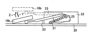
図2は図1のハンドセット14の耳当て部近傍の拡大部分縦断面図である。図2はハンドセット14が筐体部12に載置された状態(オンフック状態)を示している。オンフック状態ではクレイドル(凹部)13にハンドセット14の耳あて部14aが置かれる。ハンドセット14の下にあるフックボタン18はフックボタン軸19を中心に回動可能である。図2においてフックボタン18の頭部18aはクレイドル孔13aから突出した状態(オフフック状態:図2において破線で示す状態)から矢印Xのように回動して、実線で示す位置に至る。フックボタン18の下端部(末端部)18bはフックスイッチ22のレバー23に達している。フックボタンの頭部18aが矢印Xのように回動すると、フックボタンの下端部18bはフックボタン軸19を中心に矢印Yのように回動する。このフックボタン下端部18bの回動により、フックスイッチのレバー23も矢印Yのように動く。符号20はプリント基板を示しており、符号21はフックスイッチ軸に装着されたスプリングを示している。   FIG. 2 is an enlarged partial longitudinal sectional view of the vicinity of the ear pad portion of the handset 14 of FIG. FIG. 2 shows a state (on-hook state) in which the handset 14 is placed on the housing unit 12. In the on-hook state, the ear pad 14 a of the handset 14 is placed on the cradle (recessed portion) 13. The hook button 18 under the handset 14 is rotatable about a hook button shaft 19. In FIG. 2, the head 18a of the hook button 18 rotates as indicated by an arrow X from a state protruding from the cradle hole 13a (off-hook state: a state indicated by a broken line in FIG. 2) to a position indicated by a solid line. A lower end (end portion) 18 b of the hook button 18 reaches the lever 23 of the hook switch 22. When the head 18a of the hook button is rotated as indicated by the arrow X, the lower end portion 18b of the hook button is rotated as indicated by the arrow Y about the hook button shaft 19. The lever 23 of the hook switch also moves as shown by the arrow Y by the rotation of the lower end portion 18b of the hook button. Reference numeral 20 denotes a printed circuit board, and reference numeral 21 denotes a spring attached to the hook switch shaft.

図2のフックスイッチ22の概略が図3に示されている。図2のフックボタン下端部18bとフックスイッチレバー23とプリント基板20の位置関係は、説明の都合上、図3において上下反転されている。図3において破線がオフフック状態を示し、実線がオンフック状態を示している。図3において、フックスイッチ軸25に装着されたスプリング21によりフックボタン下端部18bは矢印Z方向に付勢されている。この付勢力は図2の矢印Y方向及びX方向の反対方向の力であり、オフフック状態では、この付勢力によりフックボタン下端部18bが破線(図2及び図3)の位置に維持され、フックボタン頭部18a(図2)がクレイドル孔13a(図2)から突出するようになっている。   An outline of the hook switch 22 of FIG. 2 is shown in FIG. The positional relationship among the hook button lower end 18b, the hook switch lever 23, and the printed board 20 in FIG. 2 is inverted up and down in FIG. 3 for convenience of explanation. In FIG. 3, a broken line indicates an off-hook state, and a solid line indicates an on-hook state. In FIG. 3, the hook button lower end portion 18 b is urged in the arrow Z direction by the spring 21 attached to the hook switch shaft 25. This urging force is a force in the direction opposite to the arrow Y direction and the X direction in FIG. 2. In the off-hook state, the urging force maintains the hook button lower end 18b at the position of the broken line (FIGS. 2 and 3). The button head portion 18a (FIG. 2) protrudes from the cradle hole 13a (FIG. 2).

オンフック状態では図3においてフックボタン下端部が矢印Y方向に回動する。この回動動作に伴い、フックボタン下端部18bがフックスイッチレバー23を押し下げる(矢印Y)。その結果、電話機がオンフック状態になる。このような矢印Y方向及び矢印Z方向のフックスイッチレバー23の回動により、フックスイッチ内部に設けられている接点(図示せず)が接触状態または非接触状態となる。オフフック状態では、フックスイッチの内部に設けられている接点が非接触状態となり、通話可能状態になる(フックスイッチはON)。オンフック状態では、フックスイッチ内部の接点は接触状態(フックスイッチはOFF)となり、電話機は通話不可能状態となる。このような構造を有する電話機は例えば特許文献1に記載されている。   In the on-hook state, the lower end portion of the hook button rotates in the arrow Y direction in FIG. Along with this turning operation, the hook button lower end 18b pushes down the hook switch lever 23 (arrow Y). As a result, the telephone goes on-hook. By such rotation of the hook switch lever 23 in the arrow Y direction and the arrow Z direction, a contact (not shown) provided inside the hook switch is brought into a contact state or a non-contact state. In the off-hook state, the contact provided inside the hook switch is in a non-contact state, and a call can be made (the hook switch is ON). In the on-hook state, the contact inside the hook switch is in a contact state (the hook switch is OFF), and the telephone is in a state incapable of talking. A telephone having such a structure is described in Patent Document 1, for example.

電話機に振動や軽い衝撃等の力が加えられたときのフックスイッチの誤作動を防止する構造も提案されている。例えば特許文献2にはスイッチレバーの回転動作によりフックスイッチがON状態からOFF状態に切り替わる際(あるいはOFF状態からON状態に切り替わる際)、フックスイッチが実質的に動作しない領域(非動作領域)を設けた構造が開示されている。   There has also been proposed a structure for preventing a hook switch from malfunctioning when a force such as vibration or light impact is applied to the telephone. For example, in Patent Document 2, when the hook switch is switched from the ON state to the OFF state by the rotation of the switch lever (or when the switch is switched from the OFF state to the ON state), an area where the hook switch does not substantially operate (non-operation area) is described. The provided structure is disclosed.

特開平7−87170号公報JP-A-7-87170 特開2010−233189号公報JP 2010-233189 A

上記したフックスイッチ22はプリント基板20に搭載される電子部品として部品メーカーが製造している場合が多い。部品メーカーは1つまたは複数存在し、部品メーカー毎に特徴を持った部品を製造している。図4(a)、(b)、(c)に3種類のフックスイッチ22、122、222を例示した。電話機を製造するセットメーカーは、部品メーカーが製造するフックスイッチの中から、フックスイッチの外形寸法、種々の機械的特性(例えば、スプリング21の復帰力、フックスイッチレバー23のストローク量、耐久性、接点構造)及び部品価格等を考慮して適切な部品を選定し購入し、電話機の部品として使用している。尚、図4(b)及び(c)では図示を簡略化するためにスプリング21は示されていない。   The above-described hook switch 22 is often manufactured by a component manufacturer as an electronic component mounted on the printed circuit board 20. There are one or more parts manufacturers, and each part manufacturer manufactures a characteristic part. 4A, 4B, and 4C illustrate three types of hook switches 22, 122, and 222. FIG. A set maker that manufactures a telephone, among hook switches manufactured by a component maker, has external dimensions of the hook switch, various mechanical characteristics (for example, return force of the spring 21, stroke amount of the hook switch lever 23, durability, Appropriate parts are selected and purchased in consideration of the contact structure) and part prices, and used as parts for telephones. In FIGS. 4B and 4C, the spring 21 is not shown in order to simplify the illustration.

しかしながら、このように部品メーカーからフックスイッチを購入し電話機を組み立てるという製造スキームでは、ハンドセット(受話器)や電話機筐体の形状等をフックスイッチの形状等に合わせて設計しなければならない。また、採用するフックスイッチの構成部品の形状や特性も汎用性があるとは限らない。即ち、代替部品の入手が困難となる場合が想定される。フックスイッチが製造中止になった場合には、受話器や電話機の構造・設計を大きく変更する必要が出てくる可能性もある。1つの部品メーカーが存在しなくなった場合に代替部品メーカーを探すことも困難であると考えられる。   However, in such a manufacturing scheme in which a hook switch is purchased from a parts manufacturer and a telephone is assembled, the shape of the handset (handset) or telephone housing must be designed in accordance with the shape of the hook switch. In addition, the shape and characteristics of the hook switch components used are not necessarily versatile. That is, it is assumed that it is difficult to obtain substitute parts. If the hook switch is discontinued, the structure and design of the handset and telephone may need to be changed significantly. It is also difficult to find an alternative parts maker when one parts maker no longer exists.

本発明は上記の如き事情を鑑みてなされたものであって、汎用性の高い電話機用フックスイッチ構造を提供することを目的としている。また、そのようなフックスイッチ構造を備える電話機を提供することも目的とする。   The present invention has been made in view of the circumstances as described above, and an object thereof is to provide a highly versatile telephone hook switch structure. It is another object of the present invention to provide a telephone having such a hook switch structure.

発明を解決するための手段Means for Solving the Invention

本発明による電話機のフックスイッチ構造は、電話機のハンドセットのオフフック及びオンフックに応じてオン及びオフされるフックスイッチ構造であって、一端が電話機筐体内部に固定されたフックスイッチ胴部と、当該フックスイッチ胴部の他端から回動(弾性変形)可能に延びる自由端部と、電話機筐体内部において前記自由端部の近傍に設けられた接点部材と、電話機筐体外面からフックスイッチ胴部に延びるフックボタンとを含み、ハンドセットがオンフック状態のときにハンドセットからの力はフックボタンを介してフックスイッチ胴部を押圧して、前記自由端部を前記接点部材に接触させ、ハンドセットがオンフック状態からオフフック状態に移行する際の所定範囲において前記自由端部は回動して前記接点部材との接触を維持することを特徴とするフックスイッチ構造である。   The hook switch structure of a telephone according to the present invention is a hook switch structure that is turned on and off in response to an off-hook and an on-hook of a telephone handset, and a hook switch body having one end fixed inside the telephone casing, and the hook A free end portion that can be rotated (elastically deformed) from the other end of the switch body, a contact member provided in the vicinity of the free end inside the telephone case, and a hook switch body from the outer surface of the telephone case A hook button that extends, and when the handset is in the on-hook state, the force from the handset presses the hook switch body through the hook button to bring the free end into contact with the contact member, and the handset is released from the on-hook state. The free end rotates within a predetermined range when shifting to the off-hook state to maintain contact with the contact member. A hook switch structure, characterized by.

また、本発明は前記フックスイッチ構造を有する電話機であって、フックボタンの頭部は、ハンドセットがオフフック状態にあるとき、電話機筐体のクレイドルから突出し、ハンドセットがオンフック状態にあるとき、ハンドセットに押されてクレイドルの下に埋没することを特徴とする電話機も提供する。   The present invention is also a telephone having the hook switch structure, wherein the head of the hook button protrudes from the cradle of the telephone housing when the handset is in an off-hook state, and is pushed onto the handset when the handset is in an on-hook state. The telephone is also characterized by being buried under the cradle.

本発明のフックスイッチ構造によれば、ハンドセットがオンフック状態からオフフック状態に移行する際の所定範囲においてフックスイッチの自由端部が回動して接点部材との接触を維持する。よって、電話機に衝撃等が作用しても直ちにフックスイッチがONにはならず、フックスイッチの誤動作を防止することができる。この誤動作防止効果はフックスイッチ自由端部の回動という簡単な動作・構成により達成することができる。フックスイッチは胴部と自由端部から成るので、その製造は比較的容易であり、部品メーカーからフックスイッチを調達する必要はなくなる。   According to the hook switch structure of the present invention, the free end of the hook switch rotates and maintains contact with the contact member within a predetermined range when the handset shifts from the on-hook state to the off-hook state. Therefore, even if an impact or the like is applied to the telephone, the hook switch is not immediately turned on, and malfunction of the hook switch can be prevented. This malfunction prevention effect can be achieved by a simple operation and configuration of turning the hook switch free end. Since the hook switch is composed of a body portion and a free end portion, its manufacture is relatively easy, and it is not necessary to procure the hook switch from a component manufacturer.

図1は電話機の側面図である。FIG. 1 is a side view of a telephone. 図2は図1の電話機の拡大部分縦断面図である。FIG. 2 is an enlarged partial longitudinal sectional view of the telephone shown in FIG. 図3は図2のフックスイッチの動作を説明するための拡大断面図である。FIG. 3 is an enlarged cross-sectional view for explaining the operation of the hook switch of FIG. 図4(a)、(b)、(c)は種々のフックスイッチ形状を示す図である。4A, 4B, and 4C are views showing various hook switch shapes. 図5(a)は本発明の実施例に係るフックスイッチを備えた電話機の拡大部分縦断面図であり、オフフック状態を示し、(b)は矢印Aから見た図である。FIG. 5A is an enlarged partial vertical sectional view of a telephone provided with a hook switch according to an embodiment of the present invention, showing an off-hook state, and FIG. 5B is a view seen from an arrow A. FIG. 図6はオンフック状態のフックスイッチ及びその周辺部品の拡大部分断面図である。FIG. 6 is an enlarged partial sectional view of the hook switch in the on-hook state and its peripheral parts. 図7は図5及び図6のフックスイッチの側面図であり、(a)はオフフック状態を示し、(b)はオンフック状態になった直後の状態を示し、(c)はハンドセットが完全にクレイドルに載置された状態を示している。FIG. 7 is a side view of the hook switch of FIG. 5 and FIG. 6, (a) shows the off-hook state, (b) shows the state immediately after entering the on-hook state, and (c) shows the handset completely cradle. It shows the state of being placed on. 図8は図7のフックスイッチの斜視図である。FIG. 8 is a perspective view of the hook switch of FIG. 図9は図7のフックスイッチの動作図である。FIG. 9 is an operation diagram of the hook switch of FIG.

以下に本発明の実施例を添付図面に基づいて説明する。   Embodiments of the present invention will be described below with reference to the accompanying drawings.

本実施例のフックスイッチは図1に示された電話機10に使用されるフックスイッチである。図1に示されているように電話機10は筐体部12と当該筐体部12の上に載置されるハンドセット14を有している。   The hook switch of this embodiment is a hook switch used in the telephone 10 shown in FIG. As shown in FIG. 1, the telephone 10 includes a housing unit 12 and a handset 14 placed on the housing unit 12.

まず、本発明のフックスイッチを備える電話機10のオフフック状態とオンフック状態の基本的な動作とこれに関連する構成について図5及び図6を参照して説明する。尚、図1〜図4で説明した内容と同様なものについては以下の記載においても同じ参照符号を用いて説明する。   First, the basic operation in the off-hook state and the on-hook state of the telephone 10 having the hook switch of the present invention and the configuration related thereto will be described with reference to FIGS. In addition, about the thing similar to the content demonstrated in FIGS. 1-4, it demonstrates using the same referential mark also in the following description.

図5(a)はハンドセット14を持ち上げた状態(オフフック状態)における筐体部12の内部構造を示す部分断面図である。筐体部12は、本体(ハウジング)16とフックボタン18とプリント基板20とフックスイッチ30を有している。筐体部本体16の右上部にはクレイドル(凹部)13が形成されている。クレイドル13にはハンドセット14の耳あて部14a(図6)が置かれる。フックボタン18はフックボタン軸19を中心に回動可能である。図5(a)においてフックボタン18の頭部(上端部)18aはクレイドル13に形成された孔13aから上方に突出している。フックボタン18はその頭部18aの近傍においてフックボタン軸19に支持され、プリント基板20の下方まで延び、その後、プリント基板20の下面に沿って左方向へ延びている。フックボタン18の下端部(末端部)18bにはフックスイッチ30の自由端部31近傍が当接している。フックスイッチ30の他端(基端)30aはプリント基板20に固定された固定端である。フックスイッチ30の基端30aは本実施例では、プリント基板20の下面に半田付けされている。フックスイッチ30の材料は適度な弾性と導電率を有するものを使用する。本実施例では価格も考慮して、りん青銅(t=0.2mm)を使用する。   FIG. 5A is a partial cross-sectional view showing the internal structure of the housing 12 in a state where the handset 14 is lifted (off-hook state). The casing 12 includes a main body (housing) 16, a hook button 18, a printed circuit board 20, and a hook switch 30. A cradle (concave portion) 13 is formed in the upper right portion of the housing main body 16. The cradle 13 is provided with an ear pad 14 a (FIG. 6) of the handset 14. The hook button 18 is rotatable about a hook button shaft 19. In FIG. 5A, the head (upper end) 18 a of the hook button 18 projects upward from a hole 13 a formed in the cradle 13. The hook button 18 is supported by the hook button shaft 19 in the vicinity of the head portion 18a, extends below the printed circuit board 20, and then extends leftward along the lower surface of the printed circuit board 20. The vicinity of the free end portion 31 of the hook switch 30 is in contact with the lower end portion (end portion) 18 b of the hook button 18. The other end (base end) 30 a of the hook switch 30 is a fixed end fixed to the printed circuit board 20. The base end 30a of the hook switch 30 is soldered to the lower surface of the printed circuit board 20 in this embodiment. The hook switch 30 is made of a material having appropriate elasticity and conductivity. In this embodiment, phosphor bronze (t = 0.2 mm) is used in consideration of the price.

フックスイッチ30はプリント基板20に固定されており且つ適度な弾性を有する。この弾性を利用して、図5(a)の状態にあっては、フックスイッチ30の自由端部31がフックボタン下端部18bに下向きの付勢力(反時計方向の付勢力)をかけるようになっている。この付勢力によりフックボタン18はフックボタン軸19を中心に反時計方向に付勢されるので、オフフック状態においてはフックボタンの頭部18aがクレイドル孔13aから突出した状態に維持される。プリント基板20は筐体部本体16内に固定されている。   The hook switch 30 is fixed to the printed circuit board 20 and has appropriate elasticity. 5A, the free end 31 of the hook switch 30 applies a downward biasing force (counterclockwise biasing force) to the hook button lower end 18b. It has become. Because of this biasing force, the hook button 18 is biased counterclockwise about the hook button shaft 19, so that the head 18a of the hook button is kept protruding from the cradle hole 13a in the off-hook state. The printed circuit board 20 is fixed in the casing body 16.

図5(b)は図5(a)の矢印Aの方向からフックボタン18とフックスイッチ30とクレイドル13を見た様子を示している。図5(b)からわかるようにフックボタン18はフックボタン軸19よりも上の部分(頭部)がクレイドル側に延び、フックボタン軸19より下の部分はまずフックボタン軸方向に延び、その後、垂直に屈曲し、再度フックボタン軸方向に延びてフックスイッチ30の自由端部31に至っている。フックボタンの末端部18bがフックスイッチ30の自由端部31に当接している。プリント基板20はクレイドル13の隣に位置している。   FIG. 5B shows a state in which the hook button 18, the hook switch 30, and the cradle 13 are viewed from the direction of arrow A in FIG. As can be seen from FIG. 5 (b), the hook button 18 has a portion (head) above the hook button shaft 19 extending toward the cradle, and a portion below the hook button shaft 19 first extends in the hook button shaft direction. , Bent vertically and extended again in the hook button axial direction to reach the free end 31 of the hook switch 30. The end 18 b of the hook button is in contact with the free end 31 of the hook switch 30. The printed circuit board 20 is located next to the cradle 13.

図6はハンドセット14の耳当て部14aをクレイドル13に載置した状態(オンフック状態)を示す断面図である。図5(a)を参照しつつ図6を見るとわかるように、ハンドセット耳当て部14aがクレイドル13に載置されると、ハンドセット14の自重によりフックボタン頭部18aがフックボタン軸19を中心に時計方向に回転し(矢印X)、フックボタン頭部18aはクレイドル孔13aに埋没する。フックスイッチ30の付勢力よりハンドセット14の自重の方が大きいので、フックボタン頭部18aは時計方向に回転することができる。この回転動作に伴い、フックボタンの下端側18bも時計方向に回転し(矢印Y)、フックボタン下端部18bがフックスイッチ自由端部31を押し上げる。その結果、電話機10がオンフック状態になる。オンフック状態では電話機10による通話が不可能となる。この状態では、フックスイッチ30の内部に設けられている接点は接触状態となり、通話機能OFF状態になる(フックスイッチOFF)。尚、図6においてハンドセット14をクレイドル13に載置する前のフックボタン18は破線で示されている。フックボタン18の回転動作中、フックボタン軸19の位置は不変であり、プリント基板20の位置も不変である。   FIG. 6 is a cross-sectional view showing a state (on-hook state) in which the ear pad 14 a of the handset 14 is placed on the cradle 13. As can be seen from FIG. 6 with reference to FIG. 5 (a), when the handset ear pad 14 a is placed on the cradle 13, the hook button head 18 a is centered on the hook button shaft 19 due to its own weight. The hook button head 18a is buried in the cradle hole 13a. Since the weight of the handset 14 is greater than the urging force of the hook switch 30, the hook button head 18a can rotate clockwise. With this rotation operation, the lower end side 18b of the hook button also rotates clockwise (arrow Y), and the hook button lower end portion 18b pushes up the hook switch free end portion 31. As a result, the telephone 10 enters an on-hook state. In the on-hook state, the telephone 10 cannot make a call. In this state, the contact provided in the hook switch 30 is in a contact state, and the call function is turned off (hook switch off). In FIG. 6, the hook button 18 before the handset 14 is placed on the cradle 13 is indicated by a broken line. During the rotation operation of the hook button 18, the position of the hook button shaft 19 is not changed, and the position of the printed circuit board 20 is not changed.

図6の状態からハンドセットを持ち上げると、フックスイッチ30からの付勢力により、クレイドル孔13aに埋没していたフックボタン頭部18aが上方に回動してクレイドル孔13aから突出し、フックボタン18及びフックスイッチ30が図5(a)の状態に戻り、オフフック状態となる。オフフック状態では電話機10による通話が可能となる。この状態では、フックスイッチ30の内部に設けられている接点は非接触状態となり、通話機能ON状態になる(フックスイッチON)。   When the handset is lifted from the state of FIG. 6, the hook button head 18a embedded in the cradle hole 13a is rotated upward by the urging force from the hook switch 30 and protrudes from the cradle hole 13a. The switch 30 returns to the state shown in FIG. 5A and enters an off-hook state. In the off-hook state, the telephone 10 can make a call. In this state, the contact provided in the hook switch 30 is in a non-contact state and the call function is turned on (hook switch on).

図7は図5及び図6に示したフックボタン下端部18bとフックスイッチ30を拡大して示した図である。尚、図7では説明の都合上、図5に示されているフックボタン下端部18b、フックスイッチ30及びプリント基板20の位置関係は上下が逆になっている。図6の矢印Yと図7の矢印Yは同じ動作を示す矢印である。   FIG. 7 is an enlarged view of the hook button lower end portion 18b and the hook switch 30 shown in FIGS. In FIG. 7, for convenience of explanation, the positional relationship among the hook button lower end portion 18b, the hook switch 30, and the printed circuit board 20 shown in FIG. The arrow Y in FIG. 6 and the arrow Y in FIG. 7 are arrows indicating the same operation.

本実施例のフックスイッチ30は、電話機10に振動や軽い衝撃等の力が加えられたときのフックスイッチ30の誤作動を防止する構造を備えている。この構造により、フックスイッチ30がOFF状態からON状態に切り替わる際、フックスイッチ30が実質的に動作しない領域(非動作領域)を設けている。この構造についても図7に基づいて説明をする。   The hook switch 30 of the present embodiment has a structure that prevents malfunction of the hook switch 30 when a force such as vibration or light impact is applied to the telephone 10. With this structure, when the hook switch 30 is switched from the OFF state to the ON state, an area (non-operation area) where the hook switch 30 does not substantially operate is provided. This structure will also be described with reference to FIG.

図7(a)はオフフック状態を示し、図7(b)はオフフック状態からオンフック状態になった状態を示している。図7(c)もオンフック状態を示しているが、図7(b)から図7(c)に変わる際、フックボタン下端部18bは下方に移動しているが、フックスイッチ30のオン・オフ状態は変わらない(OFF状態のままである)。図7(b)から図7(c)の間を本実施例では非動作領域と称する。   FIG. 7A shows an off-hook state, and FIG. 7B shows a state where the off-hook state is changed to the on-hook state. FIG. 7C also shows the on-hook state, but when changing from FIG. 7B to FIG. 7C, the hook button lower end 18b moves downward, but the hook switch 30 is turned on / off. The state does not change (it remains in the OFF state). 7B to 7C is referred to as a non-operation area in this embodiment.

オフフック状態(図7(a))においては、フックスイッチ30は当初の形状・位置を取る。フックスイッチ30は、プリント基板20に固定されている基端部30aと、基端部30aから垂直に延びてその後プリント基板20にほぼ平行に延びる胴部30bと、胴部30bの先端に設けられた(形成された)自由端部31とからなる。自由端部31は底浅の皿のような形状を有している。この自由端部31は胴部30bの先端(右端)を中心として胴部方向に回動(弾性変形)可能になっている。フックスイッチ30はY方向とは反対の方向に付勢力を発生しており、フックスイッチ30の当初形状・位置はフックボタン下端部18bにより決められる。この状態において、フックスイッチ30の自由端部31は胴部30bとプリント基板20の間に位置している。図8はフックスイッチ30の斜視図である。本実施例ではフックスイッチ30の基端部30aは2つの折り曲げ部を有しており、折り曲げ部がプリント基板20に固定されている。また、基端部30aと胴部30bと自由端部31は一体的に(1ピース部品として)形成されている。自由端部31は下方に凸状の曲面部31aを有している。自由端部31は、例えば、1枚の長方形材料の頭部をプレス加工することにより形成することができる。フックスイッチは弾性体である。   In the off-hook state (FIG. 7A), the hook switch 30 takes the initial shape and position. The hook switch 30 is provided at a base end portion 30a fixed to the printed circuit board 20, a body portion 30b extending perpendicularly from the base end portion 30a and thereafter extending substantially parallel to the printed circuit board 20, and a front end of the body portion 30b. And a free end portion 31 (formed). The free end 31 has a shape like a shallow dish. The free end 31 is rotatable (elastically deformed) in the body direction around the tip (right end) of the body 30b. The hook switch 30 generates a biasing force in a direction opposite to the Y direction, and the initial shape and position of the hook switch 30 is determined by the hook button lower end 18b. In this state, the free end portion 31 of the hook switch 30 is located between the trunk portion 30 b and the printed board 20. FIG. 8 is a perspective view of the hook switch 30. In this embodiment, the base end portion 30 a of the hook switch 30 has two bent portions, and the bent portions are fixed to the printed circuit board 20. Further, the base end portion 30a, the body portion 30b, and the free end portion 31 are integrally formed (as a one-piece component). The free end portion 31 has a curved surface portion 31a that is convex downward. The free end 31 can be formed by, for example, pressing a rectangular material head. The hook switch is an elastic body.

ハンドセット14がクレイドル13に載置されると、フックボタン下端部18bは図7(a)の位置から図7(b)の位置に移動する(矢印Y)。フックボタン下端部18bはフックスイッチの胴部30b先端に当接しており、フックボタン下端部18bのY方向移動に伴い、フックスイッチ30の胴部先端及びこれに繋がっている自由端部31もY方向に移動する。この間、フックスイッチの基端30aの位置は不変であり、胴部30bは基端30aを基に弾性変形する。フックボタン下端部18bが所定距離Y方向に移動すると、フックスイッチ30の自由端部31がプリント基板20に接する。この状態が図7(b)に示されている。この状態になると、フックスイッチはOFFになり、通話不能状態となる。但し、この状態では、ハンドセットの耳当て部14aは完全にクレイドル13に納まっていない。つまり、フックボタン頭部18aはクレイドル穴13aに完全に埋没していない。図7(a)から図7(b)への移動は、ハンドセット14からの力がフックボタン18を介して胴部30bを押圧して自由端部31をプリント基板20に接触させた結果である。尚、プリント基板20は自由端部31に接触するので、プリント基板20を接点部材と称することができる。この接点部材(プリント基板20)は電話機筐体内部において自由端部31の近傍に設けられている。   When the handset 14 is placed on the cradle 13, the lower end portion 18b of the hook button moves from the position shown in FIG. 7A to the position shown in FIG. 7B (arrow Y). The hook button lower end 18b is in contact with the tip of the body 30b of the hook switch. As the hook button lower end 18b moves in the Y direction, the end of the body of the hook switch 30 and the free end 31 connected thereto are also Y. Move in the direction. During this time, the position of the base end 30a of the hook switch is not changed, and the body 30b is elastically deformed based on the base end 30a. When the hook button lower end 18 b moves in the Y direction for a predetermined distance, the free end 31 of the hook switch 30 contacts the printed circuit board 20. This state is shown in FIG. In this state, the hook switch is turned off, and the telephone call is disabled. However, in this state, the ear pad 14a of the handset is not completely stored in the cradle 13. That is, the hook button head portion 18a is not completely buried in the cradle hole 13a. The movement from FIG. 7A to FIG. 7B is a result of the force from the handset 14 pressing the trunk portion 30b via the hook button 18 to bring the free end 31 into contact with the printed circuit board 20. . In addition, since the printed circuit board 20 contacts the free end part 31, the printed circuit board 20 can be called a contact member. This contact member (printed circuit board 20) is provided in the vicinity of the free end 31 inside the telephone casing.

図7(b)から図7(c)への移動は、フックボタン頭部18aがクレイドル孔13aに完全に埋没する際の移動である。すなわち、図7(b)の状態ではフックボタン頭部18aがわずかにクレイドル孔13aから突出しているので、さらに下方に移動する余地がある。つまり、フックボタン下端部18bもさらに移動する余地がある。フックボタン下端部18bが図7(b)の位置から図7(c)の位置へ移動する際、フックスイッチ30の自由端部31はプリント基板20に接触したままである。詳しくは自由端部31の曲面部31aが転動しながらプリント基板20に接触し続ける。フックスイッチ30の自由端部31は胴部先端を中心として回動(弾性変形)できるので、図7(b)から図7(c)になる間、自由端部31はプリント基板20に接触したまま回動(転動)する。最終的には自由端部31はフックスイッチ30の胴部30bに当接する。このとき、自由端部31の曲面部31aの最下部がプリント基板20に接触する。よって、この間、フックスイッチ30はOFF状態のままである。図7(c)の状態でハンドセットの耳当て部14aはクレイドル13に完全に納まった状態となり、フックボタン頭部18aはクレイドル孔13aに完全に埋没した状態となる(図6の実線)。尚、図7(b)から図7(c)へ移行する際のフックスイッチ30の自由端部31の上記回動(胴部先端を中心にした回動)は、フックスイッチ30全体で考えた場合、フックスイッチ30の弾性変形であると言える。図7(a)から図7(c)への動作をフックボタン18から見ると、フックボタン18の押下動作と表現することができる。図7(a)から図7(b)への移行(あるいは図7(a)から図7(b)を経て図7(c)に至る移行)もフックスイッチ30全体で見た場合、フックスイッチ30の弾性変形であると言える。   The movement from FIG. 7B to FIG. 7C is the movement when the hook button head portion 18a is completely buried in the cradle hole 13a. That is, in the state of FIG. 7B, the hook button head 18a slightly protrudes from the cradle hole 13a, so there is room for further downward movement. That is, there is room for further movement of the hook button lower end 18b. When the hook button lower end 18b moves from the position shown in FIG. 7B to the position shown in FIG. 7C, the free end 31 of the hook switch 30 remains in contact with the printed circuit board 20. Specifically, the curved surface portion 31a of the free end portion 31 continues to contact the printed circuit board 20 while rolling. Since the free end portion 31 of the hook switch 30 can be rotated (elastically deformed) about the front end of the body portion, the free end portion 31 is in contact with the printed circuit board 20 during the period from FIG. 7B to FIG. It rotates (rolls) as it is. Ultimately, the free end portion 31 comes into contact with the body portion 30 b of the hook switch 30. At this time, the lowermost portion of the curved surface portion 31 a of the free end portion 31 contacts the printed circuit board 20. Therefore, during this time, the hook switch 30 remains in the OFF state. In the state of FIG. 7C, the ear pad 14a of the handset is completely stored in the cradle 13, and the hook button head 18a is completely buried in the cradle hole 13a (solid line in FIG. 6). Note that the above-described rotation of the free end portion 31 of the hook switch 30 at the time of transition from FIG. 7B to FIG. In this case, it can be said that the hook switch 30 is elastically deformed. When the operation from FIG. 7A to FIG. 7C is viewed from the hook button 18, it can be expressed as a pressing operation of the hook button 18. When the transition from FIG. 7 (a) to FIG. 7 (b) (or the transition from FIG. 7 (a) to FIG. 7 (c) through FIG. 7 (c)) is also seen in the hook switch 30 as a whole, the hook switch It can be said that it is 30 elastic deformations.

図7(c)の状態からハンドセットが上げられると、図7(b)の状態を経て、図7(a)の状態(オフフック状態)になり、フックスイッチ30及びその自由端部31は当初の位置に戻る。図7(c)から図7(a)への動作をフックボタン18から見ると、フックボタン18の解放動作と表現することができる。   When the handset is lifted from the state of FIG. 7 (c), the state of FIG. 7 (a) (off-hook state) is obtained through the state of FIG. 7 (b), and the hook switch 30 and its free end portion 31 are Return to position. When the operation from FIG. 7C to FIG. 7A is viewed from the hook button 18, it can be expressed as a release operation of the hook button 18.

本実施例では、例えば、ハンドセットの荷重が75g〜100g程度であるとすると、この荷重によりフックスイッチ30が図7(a)の状態から図7(c)の状態に弾性変形するようになっている。フックスイッチ30が発生する付勢力の大きさは、図7(b)の状態でプリント基板20と自由端部31が十分な接触をするような値にされる。また、図7(a)〜図7(c)の間の動作によりフックスイッチ30は塑性変形しない。   In this embodiment, for example, if the load of the handset is about 75 g to 100 g, the hook switch 30 is elastically deformed from the state of FIG. 7A to the state of FIG. Yes. The magnitude of the urging force generated by the hook switch 30 is set to such a value that the printed circuit board 20 and the free end 31 make sufficient contact in the state shown in FIG. Further, the hook switch 30 is not plastically deformed by the operation between FIGS. 7A to 7C.

本実施例のフックスイッチ30によれば、電話機10に振動や軽い衝撃等の力が加えられたときのフックスイッチ30の誤作動を防止することができる。そのためにフックスイッチ30は、フックボタン18の回動によりOFF状態からON状態に切り替わる際、フックスイッチが実質的に動作しない領域(非動作領域)を有している。図9はこの非動作領域を説明するための図である。図9に示されているように、ハンドセットを電話機筐体部12から持ち上げる場合(オンフック状態からオフフック状態に移行する際)、フックボタン下端部18bが所定範囲(所定距離)移動してもフックスイッチ30はプリント基板20から離れない(図7(c)から図7(b)の間)。この間では、フックスイッチ30の自由端部31がプリント基板20に接触したままである(自由端部31は回動してプリント基板20との接触を維持する)ので、フックスイッチ30はOFFのままである(通話機能OFF)。つまり、ハンドセット14を電話機筐体12から持ち上げても、所定範囲(非動作領域)ではフックスイッチ30が実質的に動作しないようになっている(フックボタン18は動くが、その動きがフックスイッチ接点の接触非接触動作とは無関係になっている)。その後さらにハンドセット14が持ち上げられると、フックスイッチ30(さらに具体的には自由端部31)がプリント基板20から離れる(図9のON領域)。これが図7(b)から図7(a)への移行である。   According to the hook switch 30 of the present embodiment, malfunction of the hook switch 30 when a force such as vibration or light impact is applied to the telephone 10 can be prevented. Therefore, the hook switch 30 has a region (non-operating region) where the hook switch does not substantially operate when the hook button 18 is switched from the OFF state to the ON state by the rotation of the hook button 18. FIG. 9 is a diagram for explaining this non-operation area. As shown in FIG. 9, when the handset is lifted from the telephone case 12 (when shifting from the on-hook state to the off-hook state), even if the hook button lower end 18b moves within a predetermined range (predetermined distance), the hook switch 30 does not leave the printed circuit board 20 (between FIG. 7C and FIG. 7B). During this period, the free end 31 of the hook switch 30 remains in contact with the printed circuit board 20 (the free end 31 rotates to maintain contact with the printed circuit board 20), so the hook switch 30 remains off. (Call function OFF). That is, even when the handset 14 is lifted from the telephone housing 12, the hook switch 30 is substantially inoperative within a predetermined range (non-operating area) (the hook button 18 moves, but the movement is a hook switch contact). This is unrelated to the non-contact operation of the contact). Thereafter, when the handset 14 is further lifted, the hook switch 30 (more specifically, the free end portion 31) is separated from the printed circuit board 20 (ON region in FIG. 9). This is the transition from FIG. 7 (b) to FIG. 7 (a).

尚、図7(b)から図7(c)への移行または図7(c)から図7(b)への移行の際の自由端部31の曲面部31aの動きは、プリント基板20との関係で表現すれば、プリント基板20に接触しながらプリント基板20上を転動していると言える。   Note that the movement of the curved surface portion 31a of the free end portion 31 during the transition from FIG. 7B to FIG. 7C or the transition from FIG. 7C to FIG. It can be said that it is rolling on the printed circuit board 20 while contacting the printed circuit board 20.

図9の「非動作領域」の右のわずかなOFF領域が従来の電話機のOFF領域であり、このように小さなOFF領域しかないとすると、電話機に軽い衝撃が作用した場合に直ちにON領域に入ってしまう。本実施例では、従来のOFF領域にプラスして非動作領域を設けたので、電話機に衝撃が作用しても直ちにON領域には入らない。オンフック状態において電話機10に衝撃が作用しても非動作領域の範囲でフックボタン下端部18bが移動する限り、電話機が通話可能状態になることはない。図9の非動作領域ではフックスイッチの接点は接触状態に維持される(フックスイッチはOFF)。尚、本実施例では非動作領域は数ミリ(例えば、1mm〜2mm程度)である。   The slight OFF area to the right of the “non-operating area” in FIG. 9 is the OFF area of the conventional telephone. If there is only such a small OFF area, it immediately enters the ON area when a light impact is applied to the telephone. End up. In this embodiment, since the non-operation area is provided in addition to the conventional OFF area, even if an impact is applied to the telephone, it does not immediately enter the ON area. Even if an impact is applied to the telephone 10 in the on-hook state, as long as the hook button lower end 18b moves in the range of the non-operation area, the telephone will not be in a call-ready state. In the non-operation area of FIG. 9, the contact of the hook switch is maintained in contact (the hook switch is OFF). In this embodiment, the non-operation area is several millimeters (for example, about 1 mm to 2 mm).

本実施例のフックスイッチ30は上記説明及び図8から分かるように、金属製の単部品であるので、複雑な金型等を必要とせず、自社製造が可能である。よって、フックスイッチ30の部品コストの低減及び部品調達性の向上を達成することができる。また、フックスイッチ30を自社製造することにより、電話機のサイズやデザインに合わせてフックスイッチ30をカスタマイズすることが可能となる。外部の部品メーカーからフックスイッチを調達しないので、フックスイッチ製造中止に伴う電話機全体の設計変更を回避することもできる。   As can be seen from the above description and FIG. 8, the hook switch 30 of the present embodiment is a single component made of metal, and thus can be manufactured in-house without requiring a complicated mold or the like. Therefore, it is possible to reduce the component cost of the hook switch 30 and improve the component procurement. In addition, by making the hook switch 30 in-house, the hook switch 30 can be customized according to the size and design of the telephone. Since a hook switch is not procured from an external parts manufacturer, it is possible to avoid a design change of the entire telephone due to the suspension of hook switch production.

尚、本発明は上記した実施例に限定されない。例えば、フックスイッチ30の材料はりん青銅としたが、りん青銅と同じ特性を有する材料であれば別の材料を採用してもよい。また、図9の非動作領域は1mm〜2mm程度としたが、それより大きくてもよい。さらに、上記の記載においては本発明のフックスイッチを固定電話機に使用した場合について説明したが、フックボタンあるいはそれと同等の機能を有する部材によりオンオフされるフックスイッチであれば、固定電話機以外(例えば、携帯型の電話機)に使用することもできる。   In addition, this invention is not limited to an above-described Example. For example, the material of the hook switch 30 is phosphor bronze, but another material may be adopted as long as it has the same characteristics as phosphor bronze. Moreover, although the non-operation area | region of FIG. 9 was about 1 mm-2 mm, it may be larger than it. Further, in the above description, the case where the hook switch of the present invention is used for a fixed telephone is described. However, any hook switch that is turned on / off by a hook button or a member having a function equivalent to the hook button (for example, a fixed telephone) It can also be used for portable telephones.

また、フックスイッチ30の胴部30bはプリント基板20に固定されるとしたが、電話機筐体部12(または本体16)の内部のプリント基板以外の部材に固定されてもよい。   In addition, although the trunk portion 30b of the hook switch 30 is fixed to the printed circuit board 20, it may be fixed to a member other than the printed circuit board inside the telephone casing 12 (or the main body 16).

さらに、前記実施例ではフックスイッチ30は一体的に形成されるとしたが、別個に用意した2つの部分から構成されるようにしてもよい。例えば、フックスイッチは板バネ部と自由端部により構成することができる。板バネ部は図7の基部30aと胴部30bからなり、自由端部は図7の自由端部31からなる。板バネ部と自由端部31は別々に製造し、板バネ部の先端に自由端部31を付設すればよい。付設する際、自由端部31が図7(b)から図7(c)に示したように回動できるような構成とする。また、板バネ部の材料は自由端部31の材料と同じでも異なってもよい。   Furthermore, although the hook switch 30 is integrally formed in the above-described embodiment, it may be configured by two parts prepared separately. For example, the hook switch can be composed of a leaf spring portion and a free end portion. The leaf spring portion is composed of the base portion 30a and the body portion 30b in FIG. 7, and the free end portion is composed of the free end portion 31 in FIG. The leaf spring portion and the free end portion 31 may be manufactured separately, and the free end portion 31 may be attached to the tip of the leaf spring portion. At the time of attachment, the free end 31 is configured to be rotatable as shown in FIGS. 7B to 7C. Further, the material of the leaf spring part may be the same as or different from the material of the free end part 31.

本発明のフックスイッチは、電話機のハンドセットのオンフック時にハンドセットからの力を受けて移動または変形(あるいは、移動且つ変形)する部材(図7の胴部30bに相当する部材)と、当該部材から延びる回動可能部材(図7の自由端部31に相当する部材)を含み、当該回動可能部材が非動作領域を有すればよい。   The hook switch according to the present invention includes a member that moves or deforms (or moves and deforms) in response to a force from the handset when the telephone handset is on-hook, and a member that corresponds to the trunk portion 30b of FIG. It is only necessary to include a rotatable member (a member corresponding to the free end portion 31 in FIG. 7), and the rotatable member has a non-operation area.

10 電話機
12 筐体部
13 クレイドル
14 ハンドセット
18 フックボタン
20 プリント基板(接点部材)
30 フックスイッチ
30a 胴部
31 自由端部
31a 曲面部
10 Telephone
12 Housing 13 Cradle 14 Handset 18 Hook Button 20 Printed Circuit Board (Contact Member)
30 Hook switch
30a trunk 31 free end 31a curved surface

Claims (5)

電話機のハンドセットのオフフック及びオンフックに応じてオン及びオフされるフックスイッチ構造であって、
一端が電話機筐体内部に固定されたフックスイッチ胴部と、
前記フックスイッチ胴部の他端から回動可能に延びる自由端部と、
前記電話機筐体内部において前記自由端部の近傍に設けられた接点部材と、
前記電話機筐体外面から前記フックスイッチ胴部に延びるフックボタンとを含み、
前記ハンドセットがオンフック状態のときに前記ハンドセットからの力は前記フックボタンを介して前記フックスイッチ胴部を押圧して、前記自由端部を前記接点部材に接触させ、前記ハンドセットがオンフック状態からオフフック状態に移行する際の所定範囲において前記自由端部は回動して前記接点部材との接触を維持することを特徴とするフックスイッチ構造。
A hook switch structure that is turned on and off in response to off-hook and on-hook of a telephone handset,
A hook switch body with one end fixed inside the phone case;
A free end extending rotatably from the other end of the hook switch body,
A contact member provided in the vicinity of the free end in the telephone casing;
A hook button extending from the outer surface of the telephone casing to the hook switch body,
When the handset is in the on-hook state, the force from the handset presses the hook switch body via the hook button to bring the free end into contact with the contact member, and the handset is in the off-hook state from the on-hook state. The hook switch structure is characterized in that the free end portion is rotated and maintained in contact with the contact member within a predetermined range when shifting to (1).
前記自由端部は曲面部を有し、前記所定範囲において前記自由端部の曲面部が前記接点部材と接触し続けることを特徴とする請求項1記載のフックスイッチ構造。   The hook switch structure according to claim 1, wherein the free end portion has a curved surface portion, and the curved surface portion of the free end portion continues to contact the contact member in the predetermined range. 前記フックスイッチ胴部は弾性体であり、前記ハンドセットからの力により押圧されて弾性変形することを特徴とする請求項1または2記載のフックスイッチ構造。   The hook switch structure according to claim 1 or 2, wherein the hook switch body is an elastic body and is elastically deformed by being pressed by a force from the handset. 前記フックスイッチ胴部と前記自由端部は一体成型されていることを特徴とする請求項1、2または3記載のフックスイッチ構造。   4. The hook switch structure according to claim 1, wherein the hook switch body and the free end are integrally molded. 請求項1〜4のいずれかに記載のフックスイッチ構造を有する電話機であって、前記フックボタンの頭部は前記ハンドセットがオフフック状態にあるとき、前記電話機筐体のクレイドルから突出し、前記ハンドセットがオンフック状態にあるとき、前記ハンドセットに押されて前記クレイドルの下に埋没することを特徴とする電話機。   5. The telephone having the hook switch structure according to claim 1, wherein a head of the hook button protrudes from a cradle of the telephone housing when the handset is in an off-hook state, and the handset is on-hook. When in a state, the telephone is pushed by the handset and buried under the cradle.
JP2011072055A 2011-03-29 2011-03-29 Phone hook switch structure Active JP5533757B2 (en)

Priority Applications (1)

Application Number Priority Date Filing Date Title
JP2011072055A JP5533757B2 (en) 2011-03-29 2011-03-29 Phone hook switch structure

Applications Claiming Priority (1)

Application Number Priority Date Filing Date Title
JP2011072055A JP5533757B2 (en) 2011-03-29 2011-03-29 Phone hook switch structure

Publications (2)

Publication Number Publication Date
JP2012209651A true JP2012209651A (en) 2012-10-25
JP5533757B2 JP5533757B2 (en) 2014-06-25

Family

ID=47189073

Family Applications (1)

Application Number Title Priority Date Filing Date
JP2011072055A Active JP5533757B2 (en) 2011-03-29 2011-03-29 Phone hook switch structure

Country Status (1)

Country Link
JP (1) JP5533757B2 (en)

Citations (8)

* Cited by examiner, † Cited by third party
Publication number Priority date Publication date Assignee Title
JPS5513403U (en) * 1978-07-12 1980-01-28
JPS6037968U (en) * 1983-08-22 1985-03-15 日本電気株式会社 Structure of a switch
JPS6312111U (en) * 1986-07-09 1988-01-26
JPS6399631U (en) * 1986-12-16 1988-06-28
JPH02111961U (en) * 1989-02-17 1990-09-07
JPH09505960A (en) * 1993-12-01 1997-06-10 プレスコム A switching device for a telephone with a handset that enables replacement of accessories by replacement
JP2000278379A (en) * 1999-03-23 2000-10-06 Tamura Electric Works Ltd Hook button
JP3113021U (en) * 2005-05-09 2005-09-02 八幡電気産業株式会社 Mobile transceiver

Patent Citations (8)

* Cited by examiner, † Cited by third party
Publication number Priority date Publication date Assignee Title
JPS5513403U (en) * 1978-07-12 1980-01-28
JPS6037968U (en) * 1983-08-22 1985-03-15 日本電気株式会社 Structure of a switch
JPS6312111U (en) * 1986-07-09 1988-01-26
JPS6399631U (en) * 1986-12-16 1988-06-28
JPH02111961U (en) * 1989-02-17 1990-09-07
JPH09505960A (en) * 1993-12-01 1997-06-10 プレスコム A switching device for a telephone with a handset that enables replacement of accessories by replacement
JP2000278379A (en) * 1999-03-23 2000-10-06 Tamura Electric Works Ltd Hook button
JP3113021U (en) * 2005-05-09 2005-09-02 八幡電気産業株式会社 Mobile transceiver

Also Published As

Publication number Publication date
JP5533757B2 (en) 2014-06-25

Similar Documents

Publication Publication Date Title
JP2011096606A (en) Pogo pin type pressure-contact connector
CN111564332B (en) Composite key structure and wireless electronic device using same
JP5533757B2 (en) Phone hook switch structure
JP2011109633A (en) Side key module for mobile communication terminal
US20120305376A1 (en) Press key
CA2629690C (en) Compound operation input device
JP5359861B2 (en) Terminal board and watch
JP4512606B2 (en) Mobile terminal with buffer
JP2014192754A (en) Mechanism of charging terminal
JP2011171164A (en) Lever switch
JP2010098674A (en) Side keybutton mounting structure and portable terminal comprising the same
JP5394200B2 (en) Push button switch
JP2010157388A (en) Rotary switch
JP6662268B2 (en) Hook lever structure
CN205140821U (en) Waterproof button
US20060243578A1 (en) Button structure
CN110769621B (en) Controller for vehicle
WO2023203886A1 (en) Operation device
JP2005228590A (en) Switch device
KR200449770Y1 (en) Metal dome switch
JP4810454B2 (en) Lever switch
JP2008154109A (en) Stationary telephone set
JP4545693B2 (en) Portable electronic devices
WO2013114744A1 (en) Contact member
KR101525581B1 (en) A terminal contact

Legal Events

Date Code Title Description
A711 Notification of change in applicant

Free format text: JAPANESE INTERMEDIATE CODE: A712

Effective date: 20120813

A621 Written request for application examination

Free format text: JAPANESE INTERMEDIATE CODE: A621

Effective date: 20130920

A977 Report on retrieval

Free format text: JAPANESE INTERMEDIATE CODE: A971007

Effective date: 20140317

TRDD Decision of grant or rejection written
A01 Written decision to grant a patent or to grant a registration (utility model)

Free format text: JAPANESE INTERMEDIATE CODE: A01

Effective date: 20140401

R150 Certificate of patent or registration of utility model

Ref document number: 5533757

Country of ref document: JP

Free format text: JAPANESE INTERMEDIATE CODE: R150

A61 First payment of annual fees (during grant procedure)

Free format text: JAPANESE INTERMEDIATE CODE: A61

Effective date: 20140414