JP2012208985A - Optical disk drive, and focus pull-in or focus jump method - Google Patents
Optical disk drive, and focus pull-in or focus jump method Download PDFInfo
- Publication number
- JP2012208985A JP2012208985A JP2011073881A JP2011073881A JP2012208985A JP 2012208985 A JP2012208985 A JP 2012208985A JP 2011073881 A JP2011073881 A JP 2011073881A JP 2011073881 A JP2011073881 A JP 2011073881A JP 2012208985 A JP2012208985 A JP 2012208985A
- Authority
- JP
- Japan
- Prior art keywords
- spherical aberration
- recording layer
- aberration correction
- focus
- correction amount
- Prior art date
- Legal status (The legal status is an assumption and is not a legal conclusion. Google has not performed a legal analysis and makes no representation as to the accuracy of the status listed.)
- Withdrawn
Links
Images


Abstract
Description
本発明は記録層を複数有する光ディスクに対してデータ記録または再生を行う光ディスク装置に関するものである。 The present invention relates to an optical disc apparatus that performs data recording or reproduction on an optical disc having a plurality of recording layers.
特許文献1には「このように、本発明の多層光記録媒体では、一部の記録層の記録層識別エリアには第1の反射率を持つ第1の領域が、他の記録層の記録層識別エリアには第2の反射率を持つ第2の領域が、記録層の積層方向に沿って第1の領域の少なくとも一部と第2の領域の少なくとも一部とが互いに重なり合うように形成されている。このため、ピックアップを第1、第2の領域が重なる部位にセットしてフォーカスジャンプをおこなえば、検出される記録層からの反射光の強度は反射率に応じて異なるため、これを記録層の識別標識として用いることができる。」と記載されている。
また、特許文献2には「フォーカスジャンプ前に、トラックへの追従性の指標であるトラッキングエラー(TE)信号の振幅を記憶し、ジャンプ前のTE信号の振幅に対するジャンプ後のTE信号の振幅の比が、所定の閾値以下である場合に、ジャンプを再試行する。また、ジャンプ後に球面収差の補正値を段階的に変化させた場合、TE信号の振幅変化に極大値を検出できないときに、ジャンプを再試行する。」と記載されている。 Further, Patent Document 2 describes that “the amplitude of a tracking error (TE) signal, which is an index of track followability, is recorded before a focus jump, and the amplitude of the TE signal after the jump relative to the amplitude of the TE signal before the jump is recorded. When the ratio is equal to or less than a predetermined threshold value, the jump is retried, and when the spherical aberration correction value is changed stepwise after the jump, when the maximum value cannot be detected in the amplitude change of the TE signal, "Retry the jump."
従来のDVD二層ディスクなどでは、任意の記録層にレーザー焦点を合わせサーボ制御を行う際、反射光より得られるフォーカス誤差信号によって記録層数をカウントし、任意の記録層を識別する方法が用いられてきた。 In conventional DVD dual-layer discs and the like, when performing laser control with a laser focus on an arbitrary recording layer, a method is used in which the number of recording layers is counted by a focus error signal obtained from reflected light and the arbitrary recording layer is identified. Has been.
現在、規格化されているブルーレイディスク(Blu-ray Disc 以下、BDという)において、光ディスク表面から0.1mm近傍に複数の記録層を有し、片面から複数の記録層へのアクセスを可能とする。複数の記録層はディスクの厚み方向にマイクロメートルオーダーの厚さのカバー層を挟んで配置されている。 Currently, a standardized Blu-ray disc (hereinafter referred to as BD) has a plurality of recording layers in the vicinity of 0.1 mm from the surface of the optical disc, and allows access to the plurality of recording layers from one side. The plurality of recording layers are arranged with a cover layer having a thickness on the order of micrometers in the thickness direction of the disc.
記録層数が増加し、記録層間のカバー層厚さが変化すると、フォーカス誤差信号による識別方法では誤って異なる記録層に焦点を合わせてしまう場合が懸念される。記録層を誤ってフォーカス引き込みした場合には、従来では光ディスク上のアドレスを読むなどしか識別の方法がなく、記録層誤りと判定するためにさらに処理時間を要する。 If the number of recording layers increases and the cover layer thickness between recording layers changes, there is a concern that the identification method using the focus error signal may inadvertently focus on different recording layers. In the case where the recording layer is erroneously pulled in, conventionally, there is only an identification method such as reading an address on the optical disk, and further processing time is required to determine a recording layer error.
このような問題を解決するために特許文献1には、各記録層にデータエリアとは別に記録層を識別するための記録層識別エリアを、反射率の異なる領域として設けることによって解決する構成が提案されている。 In order to solve such a problem, Japanese Patent Application Laid-Open No. H10-228688 discloses a configuration that solves the problem by providing each recording layer with a recording layer identification area for identifying the recording layer separately from the data area as a region having a different reflectance. Proposed.
しかし、特許文献1のように、光ディスクの構造に特殊な領域を設けて記録層を判定する方法では光ディスクの製造工程が複雑となることが懸念される。また、従来ディスクとの互換性も低下する。
However, as disclosed in
また、特許文献2記載の技術は、誤って焦点が位置づけられた記録層に対して所望(目標)の記録層がいずれの方向(光ディスクの表面側またはその逆側)であるかが考慮されていない。そのため、特許文献2のような技術に3層以上の光ディスクを適用すると、誤って焦点が位置づけられた記録層が一つに定まらず、誤って焦点が位置づけられた記録層がいずれの記録層かを判別できないため、フォーカスジャンプを再試行しようとしても、所望の記録層に焦点を位置づけることができない可能性がある。 The technique described in Patent Document 2 takes into consideration which direction (the surface side of the optical disc or the opposite side) the desired (target) recording layer is relative to the recording layer in which the focal point is erroneously positioned. Absent. Therefore, when an optical disc having three or more layers is applied to a technique such as Patent Document 2, the recording layer in which the focal point is erroneously positioned is not determined to be one, and which recording layer is the recording layer in which the focal point is erroneously positioned. Therefore, even if it is attempted to retry the focus jump, there is a possibility that the focus cannot be positioned on the desired recording layer.
そこで、本発明の目的は、所望の記録層にフォーカス引き込み又はフォーカスジャンプを迅速に実行できる光ディスク装置を提供することである。 SUMMARY OF THE INVENTION An object of the present invention is to provide an optical disc apparatus capable of quickly executing focus pull-in or focus jump on a desired recording layer.
上記課題は、例えば特許請求の範囲記載の構成を採用することにより解決される。 The above-mentioned problem is solved by adopting, for example, the configuration described in the claims.
本発明によれば、所望の記録層にフォーカス引き込み又はフォーカスジャンプを迅速に実行できる光ディスク装置を提供することができる。 According to the present invention, it is possible to provide an optical disc apparatus capable of quickly performing focus pull-in or focus jump on a desired recording layer.
以下、図面を用いて実施例について説明する。また、本発明は以下の実施例に限定されるものではない。 Embodiments will be described below with reference to the drawings. The present invention is not limited to the following examples.
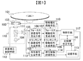
図1に本発明における実施の一形態を示す。図1において、101は片面からアクセス可能なN個(N≧3、Nは整数)の記録層を持つ光ディスクである。102はレーザー光を光ディスク101の記録層に集光するための対物レンズである。103は対物レンズ102を駆動するための駆動手段(アクチュエータ)である。104はレーザーである。例えば、半導体レーザーであり、レーザー波長は405nmである。105は光ディスク101から反射されるレーザー光を受光する受光器である。
FIG. 1 shows an embodiment of the present invention. In FIG. 1,
106は受光器105により受光されたレーザー光から光ディスク101上の焦点と記録層とのずれを示すフォーカス誤差信号を生成するフォーカス誤差信号生成手段である。107は駆動手段103を焦点方向に駆動するためのフォーカス駆動信号を生成するフォーカス駆動信号生成手段である。108は受光器105により受光されたレーザー光から光ディスク101上の焦点と記録層上のトラック溝とのずれを示すトラッキング誤差信号を生成するトラッキング誤差信号生成手段である。
A focus error
109は駆動手段103を光ディスク101の略半径方向に駆動するためのトラッキング駆動信号を生成するトラッキング駆動信号生成手段である。110は駆動信号に応じて駆動手段103に駆動電圧を供給する駆動電圧供給手段である。111は光ディスク101上に生じるの焦点における球面収差を補正する球面収差補正素子である。
Reference numeral 109 denotes a tracking drive signal generating means for generating a tracking drive signal for driving the drive means 103 in the substantially radial direction of the
112は球面収差補正素子111を駆動して収差補正を行う球面収差補正制御手段である。113は受光器105が受光した反射光から光ディスク101上に記録された情報を示す信号を生成する再生信号生成手段である。
114は前記トラッキング誤差信号または前記再生信号の振幅を測定する信号振幅計測手段である。115は計測された振幅量を記憶するための記憶手段である。記憶手段115は、例えば半導体メモリによって実装する。116は信号振幅計測手段114によって計測された信号振幅または記憶手段115に記憶された信号振幅情報から記録層の判定を行う記録層判定手段である。117は制御手段である。例えば、制御手段117は、CPU等の信号処理回路によって実装する。
図1において対物レンズ102からレーザー104、球面収差補正素子111で光ヘッド118を構成する。図1の装置は、対物レンズ102によってレーザー104から出射されるレーザー光を光ディスク101上に集光し焦点を生じる。
In FIG. 1, an
なお、本光ディスク装置において、フォーカス誤差信号生成手段106、フォーカス駆動信号生成手段107、トラッキング誤差信号生成手段108、トラッキング駆動信号生成手段109、駆動電圧供給手段110、球面収差補正制御手段112、再生信号生成手段113、信号振幅計測手段114、記憶手段115、記録層判定手段116、制御手段117は、例えば、単一のLSIやMPUによって実装するものとする。また、任意の手段を別のLSIによって実装してもよい。
In this optical disc apparatus, the focus error signal generation means 106, the focus drive signal generation means 107, the tracking error signal generation means 108, the tracking drive signal generation means 109, the drive voltage supply means 110, the spherical aberration correction control means 112, the reproduction signal. The generation unit 113, the signal
図1において、球面収差補正素子111は、レーザー104から対物レンズ102の間のレーザー光路中に配置される。球面収差補正素子111の構成は、レーザー光路中に挿入された略光軸方向に位置可変なレンズを変位させることによって球面収差を補正することができる。例えばレンズ間距離が可変の2枚以上のレンズの組合せによって、そのレンズ間距離を変化させ調整することで、通過光束の球面収差を補正することが可能な、所謂、ビームエキスパンダにより構成される。なお、球面収差補正素子111の構成はこれに限るものではなく、液晶素子などでもよい。例えば、同心円状パターンを有した液晶素子によって、光束の内周部と外周部との間に位相差をあたえることによって上記の効果を与えることが可能である。なお、一般に球面収差補正素子111にレンズの組合せを用いると、液晶素子に比べ価格が安価であり、また制御がしやすい。また、液晶素子を用いると、レンズの組合せに比べ省スペース化が図れ、また駆動時間も速くなる。
In FIG. 1, the spherical aberration correction element 111 is disposed in the laser light path between the
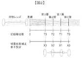
図2に球面収差補正素子111の球面収差補正量と光ディスク101上の記録層の位置との関係を示す。図2では光ディスク101が四つの記録層を有する場合を例として説明する。光ディスク101上には、対物レンズと対向する側の光ディスク101表面から、第3層、第2層、第1層、第0層の四つの記録層が順番に配置されている。このとき、ディスク表面を基準(0)として、ディスク表面から第0層〜第3層の各記録層の位置をそれぞれT0〜T3で表す(T0>T1>T2>T3)。
FIG. 2 shows the relationship between the spherical aberration correction amount of the spherical aberration correction element 111 and the position of the recording layer on the
一方、球面収差補正素子111の球面収差補正量は、素子を構成する収差補正レンズの位置に関係する。光ディスク101の第0層〜第3層に焦点を生じたとき、球面収差の影響が最も低減される収差補正レンズの位置をそれぞれX0〜X3とする。このとき、収差補正レンズの位置をX3からX0に向かう方向を正とするならば、収差補正レンズの位置にはX0>X1>X2>X3の関係がある。以下、収差補正レンズの位置を球面収差補正量と言う。
On the other hand, the spherical aberration correction amount of the spherical aberration correction element 111 is related to the position of the aberration correction lens constituting the element. When the focus is generated on the 0th layer to the 3rd layer of the
光ディスク101上の任意の記録層に焦点が位置づけされているとき、球面収差補正量が記録層に対応する補正量から大きく離れている場合、収差の影響によってトラッキング誤差信号、再生信号、反射光量などの信号振幅は低下する。
When the focal point is positioned on an arbitrary recording layer on the
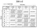
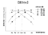
例として、四つの記録層を有する光ディスクについて、焦点の位置と球面収差補正量による信号振幅の変化の関係を、トラッキング誤差信号を例に図3(a)、(b)に図示する。 As an example, for an optical disc having four recording layers, the relationship between the focal position and the change in signal amplitude due to the spherical aberration correction amount is illustrated in FIGS. 3A and 3B by taking a tracking error signal as an example.
図3(a)では焦点が位置づけられた記録層と、球面収差補正が最適となる記録層とが一致すれば、大きな信号振幅が得られ、焦点位置または球面収差補正のどちらか一方が異なる記録層に変化すると信号振幅が低下することを示している。焦点位置または球面収差補正の変化量が大きくなればなるほど、信号振幅の低下量は大きくなる。 In FIG. 3 (a), if the recording layer on which the focal point is positioned coincides with the recording layer for which the spherical aberration correction is optimal, a large signal amplitude can be obtained, and either the focal position or the spherical aberration correction is different. It shows that the signal amplitude decreases when changing to a layer. The greater the amount of change in focal position or spherical aberration correction, the greater the amount of signal amplitude reduction.
なお、焦点位置または球面収差補正のいずれかが隣接する記録層に移動した場合、+方向に移動した場合と−方向に移動した場合とで振幅低下量は同一であるとは限らない。また、焦点位置が隣接層に移動した場合と、球面収差補正が隣接層に移動した場合との振幅低下量は同一であるとは限らない。このときの低下量の違いは、隣接する記録層との記録層間距離の違いなどのディスク構造や、光学系の構成などによって決まる。 When either the focal position or the spherical aberration correction is moved to the adjacent recording layer, the amplitude reduction amount is not always the same when moved in the + direction and when moved in the-direction. Further, the amount of amplitude reduction is not necessarily the same when the focal position is moved to the adjacent layer and when spherical aberration correction is moved to the adjacent layer. The difference in the amount of decrease at this time is determined by the disc structure such as the difference in recording layer distance between adjacent recording layers, the configuration of the optical system, and the like.
また、焦点位置と球面収差補正の位置とが一致している場合、焦点位置および球面収差補正の位置がどの記録層に位置しているかによって、振幅は異なる場合がある。 When the focal position and the spherical aberration correction position coincide with each other, the amplitude may differ depending on which recording layer the focal position and the spherical aberration correction position are located.
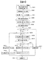
図1の装置の動作を図4のフローチャートで説明する。例として、図2のような四つの記録層を有する光ディスクを図1の装置に装着した場合について説明する。いずれの記録層に対しても焦点が合っていない状態から、四つの記録層のうち任意の記録層を目標とし焦点の位置づけを行う場合について説明する。例として第1層に焦点の位置づけを行おうとする場合について説明する。 The operation of the apparatus of FIG. 1 will be described with reference to the flowchart of FIG. As an example, a case where an optical disk having four recording layers as shown in FIG. 2 is mounted on the apparatus shown in FIG. 1 will be described. A case will be described in which the focus is positioned by targeting any recording layer among the four recording layers from a state in which none of the recording layers is in focus. As an example, a case where the focus is to be positioned on the first layer will be described.
はじめに図1の装置は、フォーカス引き込みを開始する(S401)。S402において第1層で球面収差の影響が小さくなるように、球面収差補正素子111を駆動してX1の位置に設定する。 First, the apparatus of FIG. 1 starts focus pull-in (S401). In S402, the spherical aberration correction element 111 is driven and set to the position X1 so that the influence of the spherical aberration is reduced in the first layer.
S403では、対物レンズ102を光ディスク101の厚み方向に駆動して第1層に焦点を位置づけようとする。このとき、記録層からの反射光によって得られるフォーカス誤差信号または反射光量信号によって第1層を検出するが、ディスクの反射光ばらつきや記録未記録による反射率の変動などによって、記録層数のカウントを誤るなどし、所望の記録層である第1層とは異なる記録層に焦点を位置づけてしまう場合がある。
In S403, the
S404では、信号振幅計測手段114によって、トラッキング誤差信号生成手段108で生成されるトラッキング誤差信号の振幅を計測する。ここで計測する信号は、記録層からの反射光から生成される信号で、球面収差の影響を受けるものであれば良く、例えば再生信号、反射光量、ウォブル信号であっても良い。ここで計測された信号振幅をV1とする。なお、再生信号などは、グルーブのない所謂グルーブレス多層の光ディスクである場合に有効である。
In S <b> 404, the amplitude of the tracking error signal generated by the tracking error signal generation unit 108 is measured by the signal
S405では、S404で計測されたV1と所定の信号振幅Vthとを比較する。Vthは、球面収差補正の位置をX1としたとき、焦点位置が第1層となるときに得られることが期待されるトラッキング誤差信号の振幅V11よりも低い値で、かつ焦点位置のみが隣接する記録層(第0層および第2層)にずれた場合に得られることが期待されるトラッキング誤差信号の振幅(V10およびV12)よりも大きな値として設定される固定値である(V11>Vth,Vth>V10,Vth>V12)。 In S405, V1 measured in S404 is compared with a predetermined signal amplitude Vth. Vth is a value lower than the amplitude V11 of the tracking error signal expected to be obtained when the focal position is the first layer when the spherical aberration correction position is X1, and only the focal position is adjacent. This is a fixed value set as a value larger than the amplitude (V10 and V12) of the tracking error signal expected to be obtained when the recording layer (the 0th layer and the second layer) is shifted (V11> Vth, Vth> V10, Vth> V12).
球面収差補正の位置をX1としたとき、振幅がVthより大きい値が得られれば、S410に進み、焦点位置が目標の記録層(第1層)にあると判定する。 When the spherical aberration correction position is X1, if the amplitude is larger than Vth, the process proceeds to S410, and it is determined that the focal position is in the target recording layer (first layer).
振幅がVth以下である場合、焦点位置が目標の記録層にないと判定する。どちらの方向にずれているのかを判定するため、S406の処理に進む。S406では球面収差補正量を目標の記録層の位置から−方向にずらし、X2に設定する。なお、S407では、信号振幅計測手段114によって、トラッキング誤差信号生成手段108で生成されるトラッキング誤差信号の振幅を再度計測し、ここで計測された信号振幅をV2とする。S408で、V2とS404で計測されたV1とを比較する。
When the amplitude is equal to or less than Vth, it is determined that the focal position is not in the target recording layer. In order to determine which direction is shifted, the process proceeds to S406. In S406, the spherical aberration correction amount is shifted from the target recording layer position in the negative direction and set to X2. In step S407, the signal
V2>V1の場合、現在の焦点位置に対して、球面収差補正の位置X2およびX1との関係性は、得られた振幅の大小関係(V2>V1)からX2の方が好適な収差補正位置であることになる。したがって、第1層を目標としてフォーカス引き込みを行ったが、第2層側に存在する異なる記録層に誤ってフォーカス引き込みを行っている可能性が高い。 When V2> V1, with respect to the current focal position, the relationship between the spherical aberration correction positions X2 and X1 is an aberration correction position in which X2 is more suitable from the obtained amplitude relationship (V2> V1). It will be. Therefore, although the focus pull-in is performed with the first layer as a target, there is a high possibility that the focus pull-in is erroneously performed on a different recording layer on the second layer side.
図3(b)を用いてこのときの信号振幅と収差補正量の関係を示す。V2>V1では、図3(b)においてX1からX2の範囲で右上がりとなるため、図中丸と破線で示した第2層における振幅変化と類似となる。したがって、目標の第1層から見て第2層側(−方向)の別の記録層に焦点が位置づいていると考えられる。 FIG. 3B shows the relationship between the signal amplitude and the aberration correction amount at this time. When V2> V1, since it rises to the right in the range from X1 to X2 in FIG. 3B, it is similar to the amplitude change in the second layer indicated by the circle and broken line in the figure. Therefore, it is considered that the focal point is located on another recording layer on the second layer side (− direction) when viewed from the target first layer.
この場合S415に進み、焦点位置が−方向にずれていると判定する。一方、V1≧V2の場合、S409に進む。S409では球面収差補正量を目標の記録層の位置から+方向にずらし、X0に設定する。S410で、信号振幅計測手段114によって、トラッキング誤差信号生成手段108で生成されるトラッキング誤差信号の振幅を再度計測し、ここで計測された信号振幅をV0とする。
In this case, the process proceeds to S415, and it is determined that the focal position is shifted in the negative direction. On the other hand, if V1 ≧ V2, the process proceeds to S409. In S409, the spherical aberration correction amount is shifted in the + direction from the position of the target recording layer and set to X0. In S410, the amplitude of the tracking error signal generated by the tracking error signal generating unit 108 is measured again by the signal
S411で、V0とS404で計測されたV1と比較する。V0>V1の場合、現在の焦点位置に対して、球面収差補正の位置X0およびX1との関係性は、得られた振幅の大小関係(V0>V1)からX0の方が好適な収差補正位置であることになる。したがって、第1層を目標層としてフォーカス引き込みを行ったが、第0層側に存在する異なる記録層に誤ってフォーカス引き込みを行っている可能性が高い。 In S411, V0 is compared with V1 measured in S404. In the case of V0> V1, the relationship between the spherical focus correction positions X0 and X1 with respect to the current focal position is an aberration correction position where X0 is more preferable based on the obtained amplitude relationship (V0> V1). It will be. Therefore, although the focus pull-in is performed using the first layer as the target layer, there is a high possibility that the focus pull-in is erroneously performed on a different recording layer on the 0th layer side.
図3(b)を用いてこのときの信号振幅と収差補正量の関係を示す。V0>V1かつV1≧V2の場合、図3(b)においてX0からX2の範囲で右下がりとなるため、図中ひし形と二点破線で示した第0層における振幅変化と類似となる。したがって、目標の第1層から見て第0層側(+方向)の別の記録層に焦点が位置づいていると考えられる。この場合S413に進み、焦点位置が+方向にずれていると判定する。 FIG. 3B shows the relationship between the signal amplitude and the aberration correction amount at this time. In the case of V0> V1 and V1 ≧ V2, since it falls to the right in the range of X0 to X2 in FIG. 3B, it is similar to the amplitude change in the 0th layer indicated by the rhombus and the two-dot broken line in the figure. Therefore, it is considered that the focal point is located in another recording layer on the 0th layer side (+ direction) when viewed from the target first layer. In this case, the process proceeds to S413, and it is determined that the focal position is shifted in the + direction.
一方、V1≧V0の場合、S412に進む。この場合、S404、S407、S410で計測された三つの球面収差補正位置X0、X1、X2に対応するトラッキング誤差信号振幅V0、V1、V2の関係性が、V1≧V0かつV1≧V2であり、球面収差補正位置を第1層に対応する位置X1としたときに最大振幅が得られたことになる。 On the other hand, if V1 ≧ V0, the process proceeds to S412. In this case, the relationship between the tracking error signal amplitudes V0, V1, and V2 corresponding to the three spherical aberration correction positions X0, X1, and X2 measured in S404, S407, and S410 is V1 ≧ V0 and V1 ≧ V2. When the spherical aberration correction position is the position X1 corresponding to the first layer, the maximum amplitude is obtained.
図3(b)を用いてこのときの信号振幅と収差補正量の関係を示す。V1≧V0かつV1≧V2の場合、図3(b)においてX0からX2の範囲でX1付近に信号振幅の極地が存在する。図中三角形と一点破線で示した第1層における振幅変化と類似となる。したがって、焦点位置は目標の記録層である第1層にあると判断する。 FIG. 3B shows the relationship between the signal amplitude and the aberration correction amount at this time. In the case of V1 ≧ V0 and V1 ≧ V2, in FIG. 3B, there is a signal amplitude pole in the vicinity of X1 in the range of X0 to X2. This is similar to the amplitude change in the first layer indicated by the triangle and the dashed line in the figure. Therefore, it is determined that the focal position is in the first layer which is the target recording layer.
S412、S413、S415のいずれかの処理によって、目標の記録層に対する現在の記録層のずれの方向が確定される。判定された結果が目標層と判定の場合(S412)、フォーカス引き込みは成功しているので、装置はその他の処理を継続できる。その他の処理を行う前に、球面収差補正を第1層に対応するX1の位置に戻す。 By any one of the processes of S412, S413, and S415, the current recording layer shift direction with respect to the target recording layer is determined. If the determined result is the target layer (S412), since the focus pull-in is successful, the apparatus can continue other processes. Before performing other processing, the spherical aberration correction is returned to the position of X1 corresponding to the first layer.
判定された結果が目標層である第1層でなかった場合、さらに目標層に焦点位置を移動する処理を行うことが出来る。S413、S415のいずれの場合も、球面収差補正の位置を再度目標層である第1層に対応するX1の位置に設定する。+方向にずれていると判定された場合(S413)、焦点位置を−方向に移動するため、−側に隣接する記録層に向かって、すなわち目標の第1層に向かう方向のフォーカスジャンプを行う(S414)。−方向にずれていると判定された場合(S415)は逆に+方向に隣接する記録層に向かって、すなわち目標の第1層に向かう方向のフォーカスジャンプを行う(S416)。S412,S414,S416を経て処理を終了する。 When the determined result is not the first layer which is the target layer, a process of moving the focal position to the target layer can be performed. In both cases of S413 and S415, the spherical aberration correction position is set again to the X1 position corresponding to the first layer, which is the target layer. If it is determined that the position is shifted in the + direction (S413), the focus position is moved in the-direction, so that the focus jump is performed toward the recording layer adjacent to the-side, that is, in the direction toward the target first layer. (S414). If it is determined that the direction is shifted in the negative direction (S415), the focus jump is performed in the direction toward the recording layer adjacent to the positive direction, that is, the target first layer (S416). The process ends through S412, S414, and S416.
S406で設定する収差補正位置として、第2層に最適となる球面収差位置X2の替わりに、Xp=i×X1+(1−i)×X2(iは正の数、0≦i<1)であらわされるXpを用いても良い。これにより、急激に球面収差補正量が変動することがなくなるため、フォーカスサーボの安定性への影響を低減できる。 As the aberration correction position set in S406, Xp = i × X1 + (1−i) × X2 (i is a positive number, 0 ≦ i <1) instead of the spherical aberration position X2 that is optimal for the second layer. Xp represented may be used. Thereby, since the spherical aberration correction amount does not fluctuate suddenly, the influence on the stability of the focus servo can be reduced.
Xpは記録層の間隔|T1−T2|に対して、ディスク製造による各記録層の厚み誤差がΔt以下である場合、(|Xp−X1|/|X2−X1|)>(Δt/|T1−T2|)となるようなiを選択することで、ディスクの厚み誤差による記録層の誤判定を抑制できる。ΔtはBDの場合、例えば5μm.程度である。 Xp is (| Xp-X1 | / | X2-X1 |)> (Δt / | T1 when the thickness error of each recording layer due to disk manufacture is equal to or less than Δt with respect to the recording layer spacing | T1-T2 | By selecting i such that −T2 |), erroneous determination of the recording layer due to disc thickness error can be suppressed. In the case of BD, Δt is, for example, 5 μm. Degree.
同様にS409で設定する収差補正位置として、第0層に最適となる球面収差位置X0の替わりに、Xm=j×X1+(1−j)×X2(jは正の数、0≦j<1)であらわされるXmを用いても良い。Xpと同様に、Xmは、記録層の間隔|T1−T0|に対して、ディスク製造による各記録層の厚み誤差がΔt以下である場合、(|Xp−X1|/|X1−X0|)>(Δt/|T1−T0|)となるようなjを選択することで、ディスクの厚み誤差による記録層の誤判定を抑制できる。 Similarly, Xm = j × X1 + (1−j) × X2 (j is a positive number, 0 ≦ j <1) instead of the spherical aberration position X0 that is optimal for the 0th layer as the aberration correction position set in S409. Xm represented by) may be used. Similarly to Xp, Xm is (| Xp−X1 | / | X1−X0 |) when the thickness error of each recording layer due to disk manufacture is Δt or less with respect to the recording layer spacing | T1−T0 |. By selecting j such that> (Δt / | T1-T0 |), erroneous determination of the recording layer due to the disc thickness error can be suppressed.
また、S405のVthによる記録層判定ステップは省略されても良い。S405がなくとも、記録層の判定ができるためである。但し、S404がある方が、光ディスク装置が誤ってフォーカス引き込みなどをする確率が低い場合には、全体として処理の速度は上がる。 Further, the recording layer determination step based on Vth in S405 may be omitted. This is because the recording layer can be determined without S405. However, in the case where S404 is present, if the probability that the optical disk apparatus erroneously pulls in the focus is low, the overall processing speed increases.
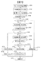
また、記録層の数は4つに限定されない。記録層の数を一般化した場合、即ち、第0層から第(N−1)層までのN個の記録層が順番に並んで配置され(Nは正の整数、N≧3)、第k層(kは正の整数、0≦k<N)にフォーカス引き込みを行う場合の処理を次に説明する。そのフローチャートを図5に示す。 Further, the number of recording layers is not limited to four. When the number of recording layers is generalized, that is, N recording layers from the 0th layer to the (N−1) th layer are arranged in order (N is a positive integer, N ≧ 3). Next, processing when focus pull-in is performed on the k layer (k is a positive integer, 0 ≦ k <N) will be described. The flowchart is shown in FIG.
まず、フォーカス引き込みを開始する(S501)。S502では球面収差補正素子111を駆動し、第k層に対応する収差補正量Xkに設定する。S503では第k層に焦点位置づけを行う。S504では信号振幅計測手段114により、トラッキング誤差信号などの指標となる振幅を計測し、この振幅をVkとする。S505ではVkとVthの比較を行い、Vk>VthであればS512に進み焦点が第k層に位置づいたと判定する。Vth>VkであればS506に進む。
First, focus pull-in is started (S501). In S502, the spherical aberration correction element 111 is driven to set the aberration correction amount Xk corresponding to the kth layer. In S503, the focus is placed on the k-th layer. In S504, the signal
S506では球面収差補正素子111を第k層の+方向に隣接する第(k+1)層に対応する球面収差補正量であるXk+1に設定する。S507では信号振幅を計測し、Vk+1とする。S508ではVk+1とVkとを比較し、Vk+1>Vkであれば、S515に進み、焦点位置が+方向の記録層にずれていると判定する。この場合、第(k+1)層に誤って焦点が位置づけられたと判定する。
In S506, the spherical aberration correction element 111 is set to
Vk≧Vk+1であれば、S509に進む。S509からS511については、第k層と−方向に隣接する第(k−1)層について、S409からS411と同様の処理を行うため、説明を省略する。また、S512〜S517はS412〜417と同様であるため説明を省略する。
If Vk
S506およびS509で設定する球面収差補正量は、S406およびS409と同様に、隣接する記録層に対応する球面収差補正量でなくても、現在の記録層と隣接する記録層との球面収差補正量から一定の比率によって求められる補正量でよい。 As in S406 and S409, the spherical aberration correction amount set in S506 and S509 is not the spherical aberration correction amount corresponding to the adjacent recording layer, but the spherical aberration correction amount between the current recording layer and the adjacent recording layer. From this, the correction amount obtained by a certain ratio may be used.
また、フォーカス引き込みの目標となる第k層が、並んで配置されたN個の記録層のうち最も端に位置する記録層の場合(k=0またはk=N−1)、他の記録層は+側か−側のどちらか一方にしか存在しない。この場合、k=0で+側の隣接記録層が存在しない場合は、S506からS508の処理を省略してもよい。逆に、k=N−1で−側の隣接記録層が存在しない場合はS509からS511の処理を省略しても良く、この場合S508の判定処理がN判定の場合は、S512に移動する。このように、記録層数が異なる場合にも適用できる。 In addition, when the k-th layer that is the target of focus pull-in is the recording layer located at the end of the N recording layers arranged side by side (k = 0 or k = N−1), the other recording layers Exists only on either the + side or the-side. In this case, if k = 0 and there is no adjacent recording layer on the + side, the processing from S506 to S508 may be omitted. On the other hand, if k = N−1 and there is no adjacent recording layer on the − side, the processing from S509 to S511 may be omitted. In this case, if the determination processing in S508 is N determination, the process proceeds to S512. As described above, the present invention can also be applied when the number of recording layers is different.
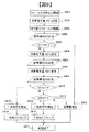
また、図5ではフォーカス引き込み時について説明したが、同様の処理をフォーカスジャンプ時に行っても良い。例えば第0層から第(N−1)層までのN個の記録層が順番に並んで配置された(Nは正の整数、N≧3)光ディスクにおいて、第a層(aは正の整数、0≦a<N)から第k層(kは正の整数、0≦k<N)にフォーカスジャンプを行う場合も層判別を行うことが出来る。その一例を図6に示す。 In FIG. 5, the focus pull-in is described, but the same processing may be performed during the focus jump. For example, in an optical disc in which N recording layers from the 0th layer to the (N−1) th layer are arranged in order (N is a positive integer, N ≧ 3), the a-th layer (a is a positive integer) , 0 ≦ a <N) to the k-th layer (k is a positive integer, 0 ≦ k <N), layer discrimination can also be performed. An example is shown in FIG.
なお、図6におけるフォーカスジャンプでは、第a層(aは正の整数、0≦a<N)から第k層(kは正の整数、0≦k<N)に焦点位置を移動する間、球面収差補正の位置を第k層に対応する位置Xkではなく、第a層に対応する位置XaとXkと係数h(hは正の数、0≦h<1)によって決まる位置Xj(Xj=h×Xk+(1−h)×Xa)の位置に設定して行う。この場合、焦点位置の移動後に球面収差補正の位置をXkにあわせる。これにより、フォーカスジャンプの際、急激に球面収差補正量が変動することがなくなるため、フォーカスサーボ外れを抑制することができる。 In the focus jump in FIG. 6, while the focal position is moved from the a-th layer (a is a positive integer, 0 ≦ a <N) to the k-th layer (k is a positive integer, 0 ≦ k <N), The position of spherical aberration correction is not the position Xk corresponding to the kth layer, but the position Xj (Xj = Xj) determined by the positions Xa and Xk corresponding to the ath layer and the coefficient h (h is a positive number, 0 ≦ h <1). Setting is performed at a position of h × Xk + (1−h) × Xa). In this case, the position of spherical aberration correction is adjusted to Xk after the focal position is moved. Thereby, since the spherical aberration correction amount does not fluctuate suddenly at the time of a focus jump, it is possible to suppress focus servo deviation.
S601にて第a層から第k層にフォーカスジャンプを開始する。このとき、焦点位置は第a層にあり、収差補正位置は第a層に対応する位置Xaにある。S602で球面収差補正素子111を駆動し、収差補正位置をXj(Xj=h×Xk+(1−h)×Xa(hは正の数、0≦h<1))の位置に設定する。hは、上述のiなどと同様の範囲で設定する。次にS603では対物レンズ102をフォーカス方向に駆動して、第k層に焦点位置を移動し、第k層でフォーカスサーボを動作させる。
In step S601, a focus jump is started from the a-th layer to the k-th layer. At this time, the focal position is in the a-th layer, and the aberration correction position is in the position Xa corresponding to the a-th layer. In step S602, the spherical aberration correction element 111 is driven, and the aberration correction position is set to a position Xj (Xj = h × Xk + (1−h) × Xa (h is a positive number, 0 ≦ h <1)). h is set in the same range as i described above. In step S603, the
次にS604で信号振幅計測手段114によって、トラッキング誤差信号生成手段108で生成されるトラッキング誤差信号の振幅を計測する。このときの振幅をVaとする。S605では球面収差補正素子111を駆動し、第k層に対応する収差補正位置Xkに設定する。
In step S <b> 604, the amplitude of the tracking error signal generated by the tracking error signal generation unit 108 is measured by the signal
S606では信号振幅計測手段114によって、トラッキング誤差信号生成手段108で生成されるトラッキング誤差信号の振幅を計測し、この信号振幅をVkとする。S607では、S606で計測されたVkと所定の信号振幅Vthとを比較する。振幅がVth以上得られれば、S612に進み、焦点位置が目標の記録層にあると判定される。
In S606, the signal
振幅がVth以下である場合、焦点位置が目標の記録層にないと判定する。どちらの方向にずれているのかを判定するため、S608の処理に進む。S608では、VkとS604で測定されたVaとを比較する。Va>Vkの場合、現在の焦点位置と、収差補正位置XkおよびXhの関係性は、得られた振幅の大小関係から、Xhの方がより収差の影響が少ない補正位置である。したがって、第k層を目標層としてフォーカスジャンプを行ったが、第k層から見て第a層側の異なる記録層に間違えてフォーカスジャンプを行っている可能性が高い。 When the amplitude is equal to or less than Vth, it is determined that the focal position is not in the target recording layer. In order to determine which direction is shifted, the process proceeds to S608. In S608, Vk is compared with Va measured in S604. In the case of Va> Vk, the relationship between the current focal position and the aberration correction positions Xk and Xh is a correction position where Xh is less affected by aberrations because of the magnitude relationship of the obtained amplitudes. Therefore, although the focus jump is performed with the kth layer as the target layer, it is highly likely that the focus jump is mistaken for a different recording layer on the ath layer side as viewed from the kth layer.
この場合S614に進み、焦点位置が第a層の方向にずれていると判定する。一方、Vk≧Vhの場合、S609に進む。S609では球面収差補正の位置をXkの位置からXaとは逆のXbの位置に設定する。S610で、信号振幅計測手段114によって、トラッキング誤差生成手段108で生成されるトラッキング誤差信号の振幅を再度計測する。このときの振幅をVbとする。
In this case, the process proceeds to S614, and it is determined that the focal position is shifted in the direction of the a-th layer. On the other hand, if Vk ≧ Vh, the process proceeds to S609. In step S609, the spherical aberration correction position is set from the Xk position to the Xb position opposite to Xa. In step S <b> 610, the amplitude of the tracking error signal generated by the tracking error generation unit 108 is measured again by the signal
S611で、VkとS610で計測されたVbとを比較する。Vb>Vkの場合、現在の焦点位置と、球面収差補正の位置XbおよびXkとの関係性は、得られた振幅の大小関係(Vb>Vk)からXbの方が好適な収差補正位置であることになる。したがって、第k層を目標層としてフォーカスジャンプを行ったが、第a層とは逆側の異なる記録層に間違えてフォーカスジャンプを行っている可能性が高い。 In S611, Vk is compared with Vb measured in S610. In the case of Vb> Vk, the relationship between the current focal position and the spherical aberration correction positions Xb and Xk is the aberration correction position where Xb is more suitable from the obtained amplitude relationship (Vb> Vk). It will be. Therefore, although the focus jump is performed with the kth layer as the target layer, there is a high possibility that the focus jump is mistaken for a different recording layer on the opposite side to the ath layer.
この場合S612に進み、焦点位置が第k層から見て第a層とは逆側にずれていると判定する。Vk≧Vbの場合、S612に進む。この場合、S604、S606、S610で計測された三つの球面収差補正位置Xj、Xh、Xbに対応するトラッキング誤差信号振幅Vh、Vk、Vbの関係性が、Vk≧VhかつVk≧Vbであり、球面収差補正位置を第k層に対応する位置Xkとしたときに最大振幅が得られたことになる。このため、焦点位置は目標の記録層である第k層にあると判断する。 In this case, the process proceeds to S612, and it is determined that the focal position is shifted to the side opposite to the a-th layer when viewed from the k-th layer. If Vk ≧ Vb, the process proceeds to S612. In this case, the relationship between the tracking error signal amplitudes Vh, Vk, and Vb corresponding to the three spherical aberration correction positions Xj, Xh, and Xb measured in S604, S606, and S610 is Vk ≧ Vh and Vk ≧ Vb, The maximum amplitude is obtained when the spherical aberration correction position is the position Xk corresponding to the k-th layer. For this reason, it is determined that the focal position is in the kth layer which is the target recording layer.
S612、S613、S615のいずれかの処理によって、目標の記録層に対する現在の記録層のずれの方向が確定される。S614,616は、図4のS414,416と同様であるため説明を省略する。 By any one of S612, S613, and S615, the current recording layer shift direction with respect to the target recording layer is determined. Since S614 and 616 are the same as S414 and 416 of FIG.
また、フォーカスジャンプの目標となる第k層が、並んで配置されたN個の記録層のうち最も端に位置する記録層の場合(k=0またはk=N−1の場合)、隣接する記録層はフォーカスジャンプ元の第a層の側にしか存在しない。この場合、S609からS611の処理を省略してもよい。この場合S608の判定処理がN判定の場合は、S612に移動する。 Further, when the kth layer that is the target of the focus jump is the recording layer located at the end of the N recording layers arranged side by side (when k = 0 or k = N−1), they are adjacent. The recording layer exists only on the side of the a-th layer that is the focus jump source. In this case, the processing from S609 to S611 may be omitted. In this case, if the determination process in S608 is N, the process moves to S612.
図6のフォーカスジャンプにおいては、S602の処理は通常のフォーカスジャンプ動作に含まれる処理である。通常のフォーカスジャンプではS605の目標の第k層に対する球面収差補正量Xkへの設定が完了して、フォーカスジャンプ処理完了となる。図6の実施例ではS604で通常のフォーカスジャンプの処理の間に追加して記録層判定のための振幅測定を行うことによって、球面収差補正量の設定の回数を軽減でき、全体の処理時間を短縮している。 In the focus jump of FIG. 6, the process of S602 is a process included in a normal focus jump operation. In the normal focus jump, the setting of the spherical aberration correction amount Xk for the target k-th layer in S605 is completed, and the focus jump process is completed. In the embodiment of FIG. 6, the number of times of setting the spherical aberration correction amount can be reduced by adding the amplitude measurement for recording layer determination in addition to the normal focus jump processing in S604, and the total processing time can be reduced. It is shortened.
図6に示したような制御を行わない場合、例えばS601のフォーカスジャンプ開始、S602の収差補正量Xj設定、S603の第k層へのフォーカス制御、S605の収差補正量Xkの手順でフォーカスジャンプを行ったあと、図4に示したようなS401から記録層判定処理を行うことが考えられる。 When the control as shown in FIG. 6 is not performed, for example, the focus jump is performed in the procedure of the focus jump start in S601, the aberration correction amount Xj setting in S602, the focus control to the k-th layer in S603, and the aberration correction amount Xk in S605. After this, it is conceivable to perform the recording layer determination process from S401 as shown in FIG.
以上本実施例によれば、誤って所望の記録層とは異なる記録層に焦点を位置づけてしまった場合において、所望の記録層にフォーカス引き込み又はフォーカスジャンプを迅速に実行できる光ディスク装置を提供することができる。 As described above, according to the present embodiment, there is provided an optical disc apparatus capable of quickly performing focus pull-in or focus jump on a desired recording layer when the focal point is mistakenly positioned on a recording layer different from the desired recording layer. Can do.
なお、収差補正を−側に駆動して計測を行うS406〜S408と、収差補正を+側に駆動して計測を行うS409〜411とは、処理の順番が入れ替わっても良い。つまり、まず、収差補正を+側に駆動して計測を行ってもよい。これを示すフローチャートを図7に示す。なお、S701〜705、S712〜717は、S401〜405,S412〜417と同様である。光ディスク装置の特性によって、収差補正を−側に駆動する処理を先に行うか、収差補正を+側に駆動する処理を先に行うかを決めればよい。また、フォーカスジャンプまたはフォーカス引き込みを行う方向に応じて、収差補正を−側に駆動する処理を先に行うか、収差補正を+側に駆動する処理を先に行うかを決めてもよい。例えば、図2おいて第3層から第1層にフォーカスジャンプをする際は、第0層に誤って焦点を合せてしまう可能性が高いとして、収差補正を+側に駆動する処理を先に行なってもよいし、第2層に誤って焦点を合せてしまう可能性が高い場合には、収差補正を−側に駆動する処理を先に行なってもよい。これにより処理速度を向上することができる。 Note that the order of processing may be interchanged between S406 to S408 in which the aberration correction is driven to the negative side and measurement is performed and S409 to 411 in which the aberration correction is driven to the positive side and measurement is performed. That is, first, the aberration correction may be driven to the + side for measurement. A flowchart showing this is shown in FIG. S701 to 705 and S712 to 717 are the same as S401 to 405 and S412 to 417. Depending on the characteristics of the optical disc apparatus, it may be determined whether the process for driving aberration correction to the negative side is performed first or the process for driving aberration correction to the positive side is performed first. Further, depending on the direction in which the focus jump or focus pull-in is performed, it may be determined whether the process for driving the aberration correction to the negative side is performed first or the process for driving the aberration correction to the positive side is performed first. For example, in FIG. 2, when performing a focus jump from the third layer to the first layer, it is highly possible that the focus is accidentally focused on the zeroth layer, and the process of driving aberration correction to the + side is first performed. If there is a high possibility that the second layer is erroneously focused, the aberration correction may be performed first. Thereby, the processing speed can be improved.
また、S407とS410の判定処理は、必ずしもS406とS409の振幅計測処理の直後に行われる必要はない。つまり、二つの振幅計測が終了した後に行われても良い。これを示すフローチャートの一例を図8に示す。また、図9に示すように図8のS810とS811が入れ替わっても良い。 Further, the determination processing in S407 and S410 does not necessarily have to be performed immediately after the amplitude measurement processing in S406 and S409. That is, it may be performed after two amplitude measurements are completed. An example of a flowchart showing this is shown in FIG. Further, as shown in FIG. 9, S810 and S811 in FIG. 8 may be interchanged.
また、S414、S416で行われるフォーカスジャンプは、現在位置づけている記録層と目標の記録層と間に存在する記録層数にかかわらず、隣接する記録層へのフォーカスジャンプ処理としてもよい。この場合、フォーカスジャンプを行った後に再度S404から判定処理を行うことで、フォーカスジャンプ後の記録層が目標の記録層かを判定して処理を行えば、記録層数のずれが2層以上のずれであったとしても、隣接する記録層へのフォーカスジャンプを繰り返し行われることで最終的には目標の記録層へ位置づけることができる。複数の記録層を一度にフォーカスジャンプするよりも、隣接の記録層へフォーカスジャンプする処理の方が焦点の移動距離が短いため安定的にフォーカスジャンプを行うことができるため、隣接の記録層へのフォーカスジャンプを繰り返し行う処理とすることで動作の安定性を高めることもできる。図5におけるS514、S516、図6におけるS614、S616、図7におけるS714、S716、図8におけるS814、S816も同様である。 The focus jump performed in S414 and S416 may be a focus jump process to an adjacent recording layer regardless of the number of recording layers existing between the currently positioned recording layer and the target recording layer. In this case, by performing the determination process from S404 again after performing the focus jump, if the process is performed after determining whether the recording layer after the focus jump is the target recording layer, the difference in the number of recording layers is two or more. Even if it is a deviation, the focus recording to the adjacent recording layer is repeatedly performed, so that it can finally be positioned to the target recording layer. Focus jump to the adjacent recording layer is shorter than the focus jump for multiple recording layers at the same time. The operation stability can be improved by performing the process of repeatedly performing the focus jump. The same applies to S514 and S516 in FIG. 5, S614 and S616 in FIG. 6, S714 and S716 in FIG. 7, and S814 and S816 in FIG.
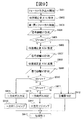
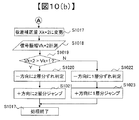
本実施例を図10(a)(b)のフローチャートを用いて説明する。実施例1と異なる点は、誤って焦点が位置付けられた記録層がどの記録層かを判定することを考慮している点である。 This embodiment will be described with reference to the flowcharts of FIGS. The difference from the first embodiment is that it is considered to determine which recording layer is the recording layer in which the focal point is erroneously positioned.
図10(a)のS1001〜S1013、S1015は、図5のS501〜S513、S515と同様であるため説明を省略する。 Since S1001 to S1013 and S1015 in FIG. 10A are the same as S501 to S513 and S515 in FIG.
S1015以降の処理を図10(b)を用いて説明する。S1015で−方向にずれていると判定したが、そのもう1つ−方向の記録層にずれている可能性もある。そのため、S1017では、球面収差補正素子111を駆動してXk+2の位置に設定する。S1018では、信号振幅計測手段114によって、トラッキング誤差信号生成手段108で生成されるトラッキング誤差信号の振幅を計測する。このときの振幅をVk+2とする。
The processing after S1015 will be described with reference to FIG. Although it is determined in S1015 that it is shifted in the-direction, there is a possibility that the recording layer is shifted in the other-direction. Therefore, in S1017, the spherical aberration correction element 111 is driven and set to the position of Xk + 2. In step S <b> 1018, the signal
S1019では、Vk+2とS1007で測定されたVk+1とを比較する。Vk+2>Vk+1の場合、現在の焦点位置と、収差補正位置Xk+2およびXk+1の関係性は、得られた振幅の大小関係から、Xk+2の方がより収差の影響が少ない補正位置である。したがって、第k層を目標層としてフォーカスジャンプを行ったが、第1層から見て2つの記録層分だけ誤ってフォーカスジャンプを行っている可能性が高い。よって、この場合、−方向に2層分ずれていると判定する(S1020)。そして、球面収差補正の位置を再度目標層である第k層に対応するXkの位置に設定し、現在焦点が合っている第(k+2)層から目標の第k層にフォーカスジャンプを行う(S1021)。 In S1019, Vk + 2 is compared with Vk + 1 measured in S1007. In the case of Vk + 2> Vk + 1, the relationship between the current focal position and the aberration correction positions Xk + 2 and Xk + 1 is a correction position where Xk + 2 is less affected by the aberration because of the magnitude relationship of the obtained amplitudes. Therefore, although the focus jump is performed using the kth layer as the target layer, it is highly possible that the focus jump is erroneously performed by two recording layers as viewed from the first layer. Therefore, in this case, it is determined that there is a shift of two layers in the negative direction (S1020). Then, the position of spherical aberration correction is set again to the position of Xk corresponding to the kth layer as the target layer, and a focus jump is performed from the currently focused (k + 2) layer to the target kth layer (S1021). ).
一方、Vk+2≦Vk+1の場合、得られた振幅の大小関係から、Xk+1の方がより収差の影響が少ない補正位置である。よって、この場合、−方向に1層分だけずれていると判定する(S1022)。そして、球面収差補正の位置を再度目標層である第k層に対応するXkの位置に設定し、現在焦点が合っている第(k+1)層から目標の第k層にフォーカスジャンプを行う(S1023)。このような処理を経て処理を終了する(S1016)。S1013以降の処理は(B以降の処理)、図10(b)とほぼ同様であるため説明を省略する。
On the other hand, in the case of Vk + 2 ≦
なお、同様の手法により3層分以上誤ってフォーカス引きこみ又はフォーカスジャンプをしてしまう可能性がある場合であっても、対応することができる。 Note that it is possible to cope with the case where there is a possibility that the focus pull-in or the focus jump may be erroneously performed by three or more layers by the same method.
以上、本実施例によれば、誤って焦点が位置付けられた記録層をがどの記録層かを判定しつつ、誤って所望の記録層とは異なる記録層に焦点を位置づけてしまった場合において、所望の記録層にフォーカス引き込み又はフォーカスジャンプを迅速に実行できる光ディスク装置を提供することができる。 As described above, according to the present embodiment, while determining which recording layer is the recording layer in which the focus is erroneously positioned, when the focus is erroneously positioned on a recording layer different from the desired recording layer, It is possible to provide an optical disc apparatus capable of quickly executing focus pull-in or focus jump on a desired recording layer.
なお、上記実施例1,2では、フォーカス引き込み又はフォーカスジャンプの開始後に、目標の記録層とは異なる記録層に対応した球面収差補正量での信号振幅を取得しているが(例えば、図3におけるV2),例えば、光ディスク装置のセットアップ時に予めこの信号振幅を取得し(フォーカスイープ中など)、記憶手段115に保持しておいてもよい。ただし、実施例1、2のようにフォーカス引き込み又はフォーカスジャンプの開始後に、球面収差補正素子を駆動し、信号振幅を取得する場合は、セットアップ時間の短縮の点などで有効である。 In the first and second embodiments, the signal amplitude at the spherical aberration correction amount corresponding to the recording layer different from the target recording layer is acquired after the start of focus pull-in or focus jump (for example, FIG. 3). V2), for example, this signal amplitude may be acquired in advance (for example, during a focus sweep) at the time of setting up the optical disk apparatus and held in the storage means 115. However, when the spherical aberration correction element is driven and the signal amplitude is acquired after the start of focus pull-in or focus jump as in the first and second embodiments, it is effective in shortening the setup time.
また、上記実施例1,2では記録層ごとに異なる球面収差補正の設定値を用いて層判定を行ったが、記録層ごとに最適な設定値が異なるものであれば、別の設定値を用いても良い。例えば、ディスクと対物レンズの相対的な傾きを補正する素子の設定値であるコマ収差補正量を用いてもよい。 In the first and second embodiments, the layer determination is performed using different spherical aberration correction setting values for each recording layer. However, if the optimum setting value is different for each recording layer, another setting value is set. It may be used. For example, a coma aberration correction amount that is a set value of an element that corrects the relative tilt between the disk and the objective lens may be used.
また、球面収差補正だけでなくコマ収差補正も上記実施例1,2に適用することにより、光ディスクのチルトの影響も考慮するこが可能となるため、より精度良く所望の記録層にフォーカス引き込み又はフォーカスジャンプを実行できる。 Further, by applying not only spherical aberration correction but also coma aberration correction to the first and second embodiments, it becomes possible to consider the influence of the tilt of the optical disc, so that the focus can be drawn into a desired recording layer with higher accuracy. Focus jump can be executed.
また、信号振幅計測手段114による信号振幅の計測が行われる間、トラッキング駆動信号生成手段109はトラッキング駆動信号を発生しない状態であっても良いし、対物レンズ102の位置がトラック横断方向について定位置を維持するように制御されても良い。
Further, while the signal amplitude is measured by the signal amplitude measuring means 114, the tracking drive signal generating means 109 may be in a state where no tracking drive signal is generated, and the position of the
また、任意の波形をトラッキング駆動信号として印加して、任意のパターンで対物レンズ102を駆動しても良い。例えばサイン波パターンの波形を印加することで、レーザー光焦点が光ディスク101のトラック上を複数横断するように駆動すれば、トラック誤差信号を安定的に出力できる。
Further, an arbitrary waveform may be applied as a tracking drive signal to drive the
101 光ディスク
102 対物レンズ
103 駆動手段
104 レーザー
105 受光器
106 フォーカス誤差信号生成手段
107 フォーカス駆動信号生成手段
108 トラッキング誤差信号生成手段
109 トラッキング駆動信号生成手段
110 駆動電圧供給手段
111 球面収差補正素子
112 球面収差補正制御手段
113 再生信号生成手段
114 信号振幅計測手段
115 記憶手段
116 記録層判定手段
117 制御手段
118 光ピックアップ
DESCRIPTION OF
Claims (22)
レーザー光を発光するレーザーと、
前記レーザーから発光されたレーザー光を前記光ディスク上に集光させる対物レンズと、
前記対物レンズを移動させる駆動部と、
前記光ディスクから反射されたレーザー光を受光する受光部と、
前記受光部により受光する反射光に対応する信号を生成する反射光信号生成部と、
前記光ディスク上に集光したレーザー光の焦点に生じる球面収差を補正する球面収差補正部と、
前記球面収差補正素子を制御する球面収差補正制御部と、を備え、
フォーカスジャンプまたはフォーカス引き込みにより、前記記録層のうちの任意の第1の記録層を目標として前記レーザー光の焦点位置を記録層に追従させるフォーカス制御を行い、前記球面収差補正制御部によって設定される球面収差補正量を、前記第1の記録層に焦点を位置づけたときに生じる球面収差を補正するための第1の球面収差補正量とは異なる第2の球面収差補正量に設定したときに前記反射光信号生成部より得られる反射光信号の信号振幅に基づいて、前記レーザー光の焦点がフォーカス制御によって追従している記録層と前記第1の記録層との位置関係を判定することを特徴とする光ディスク装置。 An optical disc apparatus capable of recording or reproducing information on an optical disc having three or more recording layers,
A laser that emits laser light;
An objective lens for condensing the laser light emitted from the laser onto the optical disc;
A drive unit for moving the objective lens;
A light receiving portion for receiving the laser light reflected from the optical disc;
A reflected light signal generation unit that generates a signal corresponding to the reflected light received by the light receiving unit;
A spherical aberration corrector for correcting spherical aberration generated at the focal point of the laser beam condensed on the optical disc;
A spherical aberration correction control unit for controlling the spherical aberration correction element,
Focus control is performed by causing the focus position of the laser beam to follow the recording layer with a focus jump or focus pulling as a target for any first recording layer of the recording layers, and is set by the spherical aberration correction control unit. When the spherical aberration correction amount is set to a second spherical aberration correction amount different from the first spherical aberration correction amount for correcting the spherical aberration generated when the focal point is positioned on the first recording layer. Based on the signal amplitude of the reflected light signal obtained from the reflected light signal generation unit, the positional relationship between the recording layer that the focal point of the laser beam follows by the focus control and the first recording layer is determined. An optical disk device.
前記球面収差補正量を第1の球面収差補正量に設定したときに前記反射光信号生成部により得られる第1の信号振幅と前記球面収差補正量を前記第2の球面収差補正量に設定したときに前記反射光信号生成部により得られる第2の信号振幅とを比較し、前記第2の信号振幅が大きいときは、前記第2の球面収差補正量に対応する第2の記録層の側に存在する記録層から第1の記録層に向かう方向に焦点位置を移動することを特徴とする光ディスク装置。 The optical disc apparatus according to claim 1,
When the spherical aberration correction amount is set to the first spherical aberration correction amount, the first signal amplitude obtained by the reflected light signal generation unit and the spherical aberration correction amount are set to the second spherical aberration correction amount. The second signal amplitude obtained by the reflected light signal generation unit is sometimes compared. When the second signal amplitude is large, the second recording layer side corresponding to the second spherical aberration correction amount is compared. An optical disc apparatus, wherein the focal position is moved in a direction from the recording layer existing in the first recording layer to the first recording layer.
前記第2の信号振幅が、前記第1の信号振幅よりも小さいときは、前記第1の球面収差補正量及び第2の球面収差補正量とは異なる第3の球面収差補正量に設定し、前記第3の球面収差補正量に設定したときに前記反射光信号生成部より得られる第3の信号振幅が前記第1の信号振幅よりも大きいときは、前記第3の球面収差補正量に対応する第3の記録層の側にある記録層から第1の記録層に向かう方向に焦点位置を移動することを特徴とする光ディスク装置。 3. The optical disc apparatus according to claim 2, wherein when the second signal amplitude is smaller than the first signal amplitude, the first spherical aberration correction amount and the second spherical aberration correction amount are different. When the third spherical aberration correction amount is set and the third signal amplitude obtained from the reflected light signal generation unit is larger than the first signal amplitude when the third spherical aberration correction amount is set. An optical disc apparatus characterized by moving the focal position in a direction from the recording layer on the side of the third recording layer corresponding to the third spherical aberration correction amount to the first recording layer.
前記第3の記録層は、前記第1の記録層からみて前記第2の記録層とは逆側の記録層が選択されることを特徴とする光ディスク装置。 The optical disk device according to claim 3,
The optical disc apparatus according to claim 3, wherein the third recording layer is a recording layer opposite to the second recording layer as viewed from the first recording layer.
フォーカスジャンプまたはフォーカス引き込み時にレーザー光焦点が変位した方向に応じて、前記第2の記録層が前記第1の記録層からみてどちらの方向に存在する記録層かを決定することを特徴とする光ディスク装置。 The optical disc device according to claim 2,
An optical disc characterized by determining in which direction the second recording layer exists as viewed from the first recording layer in accordance with a direction in which the laser beam focus is displaced during focus jump or focus pull-in apparatus.
前記第1の記録層が最も端に位置する記録層である場合、第2の球面収差補正量は、前記第1の記録層に隣接する記録層に対応する球面収差補正量であることを特徴とする光ディスク装置。 The optical disc apparatus according to claim 1,
When the first recording layer is the recording layer located at the extreme end, the second spherical aberration correction amount is a spherical aberration correction amount corresponding to a recording layer adjacent to the first recording layer. An optical disk device.
前記第2の球面収差補正量は、前記第1の記録層に焦点を位置づけた際に設定する球面収差補正量と前記第2の記録層に焦点を位置づけた際に設定する球面収差補正量との間に相当する球面収差補正量であることを特徴とする光ディスク装置。 The optical disc device according to claim 2,
The second spherical aberration correction amount includes a spherical aberration correction amount set when the focus is positioned on the first recording layer, and a spherical aberration correction amount set when the focus is positioned on the second recording layer. An optical disc apparatus characterized by a spherical aberration correction amount corresponding to
前記第2の信号振幅が前記第1の信号振幅よりも大きい場合に、前記第1の球面収差補正量及び第2の球面収差補正量とは異なる第4の球面収差補正量に設定し、
前記第4の球面収差補正量に設定したときに得られる信号振幅が前記第2の信号振幅よりも大きいときは、前記第4の球面収差補正量に対応する記録層から前記第1の記録層の方向に焦点位置を移動すること特徴とする光ディスク装置。 The optical disc device according to claim 2,
When the second signal amplitude is larger than the first signal amplitude, a fourth spherical aberration correction amount different from the first spherical aberration correction amount and the second spherical aberration correction amount is set.
When the signal amplitude obtained when the fourth spherical aberration correction amount is set is larger than the second signal amplitude, the recording layer corresponding to the fourth spherical aberration correction amount is changed to the first recording layer. An optical disc apparatus characterized in that the focal position is moved in the direction of.
前記反射光信号生成部は、レーザー光焦点と前記光ディスクの記録層上のトラック溝との位置ずれを示すトラッキング誤差信号を生成するトラッキング誤差信号生成部、前記光ディスク上に記録された情報の再生信号を生成する再生信号生成部、または前記光ディスクから反射されて前記受光部により受光されたレーザー光の強度を示す反射光量信号を生成する反射光量信号生成部のいずれかであることを特徴とする光ディスク装置。 The optical disc apparatus according to claim 1,
The reflected light signal generation unit is a tracking error signal generation unit that generates a tracking error signal indicating a positional deviation between a laser beam focus and a track groove on the recording layer of the optical disc, and a reproduction signal of information recorded on the optical disc. An optical disc, or a reflected light amount signal generating portion for generating a reflected light amount signal indicating the intensity of laser light reflected from the optical disc and received by the light receiving portion. apparatus.
前記球面収差補正素子は、前記レーザーから前記対物レンズまでのレーザー光路中に挿入された位置可変なレンズを駆動するレンズ駆動素子、または液晶素子を含んで構成されることを特徴とする光ディスク装置。 The optical disc apparatus according to claim 1,
The optical disc apparatus characterized in that the spherical aberration correction element includes a lens driving element or a liquid crystal element for driving a position variable lens inserted in a laser optical path from the laser to the objective lens.
前記球面収差補正素子に代えて、前記光ディスクと前記対物レンズの相対的な傾きを補正するコマ収差補正部を備えることを特徴とする光ディスク装置。 The optical disc apparatus according to claim 1,
An optical disc apparatus comprising a coma aberration correction unit that corrects a relative inclination between the optical disc and the objective lens, instead of the spherical aberration correction element.
レーザー光を発光し、
前記レーザー光を前記光ディスク上に集光させ、
前記光ディスクから反射されたレーザー光を受光し、
前記受光する反射光に対応する反射光信号を生成し、
前記光ディスク上に集光したレーザー光の焦点に生じる球面収差を球面収差補正部により補正し、
フォーカスジャンプまたはフォーカス引き込みにより、前記記録層のうちの任意の第1の記録層を目標として前記レーザー光の焦点位置を記録層に追従させるフォーカス制御を行い、前記球面収差補正制御部によって設定される球面収差補正量を、前記第1の記録層に焦点を位置づけたときに生じる球面収差を補正するための第1の球面収差補正量とは異なる第2の球面収差補正量に設定したときに得られる反射光信号の信号振幅に基づいて、前記レーザー光の焦点がフォーカス制御によって追従している記録層と前記第1の記録層との位置関係を判定することを特徴とするフォーカス引き込みまたはフォーカスジャンプの方法。 A method of focus pull-in or focus jump in an optical disc apparatus capable of recording or reproducing information on an optical disc having three or more recording layers,
Emits laser light,
Condensing the laser beam on the optical disc;
Receiving the laser beam reflected from the optical disc,
Generating a reflected light signal corresponding to the reflected light received;
Spherical aberration generated at the focal point of the laser beam condensed on the optical disc is corrected by a spherical aberration correction unit,
Focus control is performed by causing the focus position of the laser beam to follow the recording layer with a focus jump or focus pulling as a target for any first recording layer of the recording layers, and is set by the spherical aberration correction control unit. Obtained when the spherical aberration correction amount is set to a second spherical aberration correction amount that is different from the first spherical aberration correction amount for correcting the spherical aberration that occurs when the focal point is positioned on the first recording layer. Focus pull-in or focus jump characterized in that, based on the signal amplitude of the reflected light signal, the positional relationship between the recording layer and the first recording layer that the focal point of the laser beam follows by focus control is determined. the method of.
前記球面収差補正量を第1の球面収差補正量に設定したときに得られる第1の信号振幅よりも、前記球面収差補正量を前記第2の球面収差補正量に設定したときに得られる第2の信号振幅とを比較し、前記第2の信号振幅が大きいときは、前記第2の球面収差補正量に対応する第2の記録層の側に存在する記録層から第1の記録層に向かう方向に焦点位置を移動することを特徴とするフォーカス引き込みまたはフォーカスジャンプの方法。 A method of focus pull-in or focus jump according to claim 12,
It is obtained when the spherical aberration correction amount is set to the second spherical aberration correction amount, rather than the first signal amplitude obtained when the spherical aberration correction amount is set to the first spherical aberration correction amount. When the second signal amplitude is large, the recording layer existing on the second recording layer side corresponding to the second spherical aberration correction amount is transferred from the recording layer to the first recording layer. A method of focus pull-in or focus jump, wherein the focus position is moved in the direction of heading.
前記第2の信号振幅が、前記第1の信号振幅よりも小さいときは、前記第1の球面収差補正量及び第2の球面収差補正量とは異なる第3の球面収差補正量に設定し、前記第3の球面収差補正量に設定したときに前記反射光信号生成部より得られる第3の信号振幅が前記第1の信号振幅よりも大きいときは、前記第3の球面収差補正量に対応する第3の記録層の側にある記録層から第1の記録層に向かう方向に焦点位置を移動することを特徴とするフォーカス引き込みまたはフォーカスジャンプの方法。 A method of focus pull-in or focus jump according to claim 13,
When the second signal amplitude is smaller than the first signal amplitude, a third spherical aberration correction amount different from the first spherical aberration correction amount and the second spherical aberration correction amount is set. If the third signal amplitude obtained from the reflected light signal generation unit when set to the third spherical aberration correction amount is larger than the first signal amplitude, it corresponds to the third spherical aberration correction amount. A focus pull-in or focus jump method, wherein the focal position is moved in a direction from the recording layer on the third recording layer side toward the first recording layer.
前記第3の記録層は、前記第1の記録層からみて前記第2の記録層とは逆側の記録層が選択されることを特徴とするフォーカス引き込みまたはフォーカスジャンプの方法。 The method of focus pull-in or focus jump according to claim 14,
The focus pull-in or focus jump method is characterized in that the third recording layer is a recording layer opposite to the second recording layer as viewed from the first recording layer.
フォーカスジャンプまたはフォーカス引き込み時にレーザー光焦点が変位した方向に応じて、前記第2の記録層が前記第1の記録層からみてどちらの方向に存在する記録層かを決定することを特徴とするフォーカス引き込みまたはフォーカスジャンプの方法。 A method of focus pull-in or focus jump according to claim 13,
The focus is characterized in that in accordance with the direction in which the laser beam focus is displaced at the time of focus jump or focus pull-in, the direction in which the second recording layer is present as viewed from the first recording layer is determined. How to pull in or focus jump.
前記第1の記録層が最も端に位置する記録層である場合、第2の球面収差補正量は、前記第1の記録層に隣接する記録層に対応する球面収差補正量であることを特徴とするフォーカス引き込みまたはフォーカスジャンプの方法。 A method of focus pull-in or focus jump according to claim 12,
When the first recording layer is the recording layer located at the extreme end, the second spherical aberration correction amount is a spherical aberration correction amount corresponding to a recording layer adjacent to the first recording layer. Focus pull-in or focus jump method.
前記第2の球面収差補正量は、前記第1の記録層に焦点を位置づけた際に設定する球面収差補正量と前記第2の記録層に焦点を位置づけた際に設定する球面収差補正量との間に相当する球面収差補正量であることを特徴とするフォーカス引き込みまたはフォーカスジャンプの方法。 A method of focus pull-in or focus jump according to claim 13,
The second spherical aberration correction amount includes a spherical aberration correction amount set when the focus is positioned on the first recording layer, and a spherical aberration correction amount set when the focus is positioned on the second recording layer. A method of pulling in focus or focus jumping, characterized in that the amount of correction of spherical aberration corresponding to
前記第2の信号振幅が前記第1の信号振幅よりも大きい場合に、前記第1の球面収差補正量及び第2の球面収差補正量とは異なる第4の球面収差補正量に設定し、
前記第4の球面収差補正量に設定したときに得られる信号振幅が前記第2の信号振幅よりも大きいときは、前記第4の球面収差補正量に対応する記録層から前記第1の記録層の方向に焦点位置を移動すること特徴とするフォーカス引き込みまたはフォーカスジャンプの方法。 A method of focus pull-in or focus jump according to claim 13,
When the second signal amplitude is larger than the first signal amplitude, a fourth spherical aberration correction amount different from the first spherical aberration correction amount and the second spherical aberration correction amount is set.
When the signal amplitude obtained when the fourth spherical aberration correction amount is set is larger than the second signal amplitude, the recording layer corresponding to the fourth spherical aberration correction amount is changed to the first recording layer. A focus pull-in or focus jump method characterized by moving the focal position in the direction of.
前記反射光信号は、レーザー光焦点と前記光ディスクの記録層上のトラック溝との位置ずれを示すトラッキング誤差信号、前記光ディスク上に記録された情報の再生信号を生成する再生信号、または前記光ディスクから反射されて前記受光されたレーザー光の強度を示す反射光量信号のいずれかであることを特徴とするフォーカス引き込みまたはフォーカスジャンプの方法。 A method of focus pull-in or focus jump according to claim 12,
The reflected light signal is a tracking error signal indicating a positional deviation between a laser beam focus and a track groove on a recording layer of the optical disc, a reproduction signal for generating a reproduction signal of information recorded on the optical disc, or from the optical disc. A method of focus pull-in or focus jump, characterized in that it is one of reflected light quantity signals indicating the intensity of the reflected and received laser light.
前記球面収差補正素子は、前記レーザーから前記対物レンズまでのレーザー光路中に挿入された位置可変なレンズを駆動するレンズ駆動素子、または液晶素子を含んで構成されることを特徴とするフォーカス引き込みまたはフォーカスジャンプの方法。 A method of focus pull-in or focus jump according to claim 12,
The spherical aberration correction element includes a lens driving element that drives a position-variable lens inserted in a laser optical path from the laser to the objective lens, or a liquid crystal element. Focus jump method.
前記球面収差補正素子に代えて、前記光ディスクと前記対物レンズの相対的な傾きを補正するコマ収差補正部を備えることを特徴とするフォーカス引き込みまたはフォーカスジャンプの方法。 A method of focus pull-in or focus jump according to claim 12,
A focus pull-in or focus jump method comprising a coma aberration correction unit that corrects a relative inclination between the optical disk and the objective lens in place of the spherical aberration correction element.
Priority Applications (1)
| Application Number | Priority Date | Filing Date | Title |
|---|---|---|---|
| JP2011073881A JP2012208985A (en) | 2011-03-30 | 2011-03-30 | Optical disk drive, and focus pull-in or focus jump method |
Applications Claiming Priority (1)
| Application Number | Priority Date | Filing Date | Title |
|---|---|---|---|
| JP2011073881A JP2012208985A (en) | 2011-03-30 | 2011-03-30 | Optical disk drive, and focus pull-in or focus jump method |
Publications (1)
| Publication Number | Publication Date |
|---|---|
| JP2012208985A true JP2012208985A (en) | 2012-10-25 |
Family
ID=47188578
Family Applications (1)
| Application Number | Title | Priority Date | Filing Date |
|---|---|---|---|
| JP2011073881A Withdrawn JP2012208985A (en) | 2011-03-30 | 2011-03-30 | Optical disk drive, and focus pull-in or focus jump method |
Country Status (1)
| Country | Link |
|---|---|
| JP (1) | JP2012208985A (en) |
Cited By (1)
| Publication number | Priority date | Publication date | Assignee | Title |
|---|---|---|---|---|
| CN111755032A (en) * | 2013-07-16 | 2020-10-09 | 夏普株式会社 | Reproducing apparatus |
-
2011
- 2011-03-30 JP JP2011073881A patent/JP2012208985A/en not_active Withdrawn
Cited By (2)
| Publication number | Priority date | Publication date | Assignee | Title |
|---|---|---|---|---|
| CN111755032A (en) * | 2013-07-16 | 2020-10-09 | 夏普株式会社 | Reproducing apparatus |
| CN111755032B (en) * | 2013-07-16 | 2021-07-16 | 夏普株式会社 | Reproducing apparatus |
Similar Documents
| Publication | Publication Date | Title |
|---|---|---|
| JP4443471B2 (en) | Disc discriminating method and optical disc apparatus | |
| US7277372B2 (en) | Method and apparatus for recognizing optical discs, optical disc drive, and method and apparatus for distinguishing data storage layer | |
| JP5091836B2 (en) | Multi-layer optical disc focus jump method | |
| JP2006139841A (en) | Optical disk recording/reproducing device | |
| JP2008186537A (en) | Optical disk drive | |
| US8391112B2 (en) | Optical disk apparatus, control method, and program | |
| JP2012208985A (en) | Optical disk drive, and focus pull-in or focus jump method | |
| US20110205877A1 (en) | Optical disc drive and method for reading data from optical disc | |
| JP4139751B2 (en) | Optical disk device | |
| JP5417007B2 (en) | Optical disk device | |
| US20120033535A1 (en) | Optical disc and optical disc drive | |
| EP1998330A1 (en) | Discrimination method for optical disc types and optical disc apparatus | |
| JP5463118B2 (en) | Optical disk device | |
| JP2011076659A (en) | Optical disk apparatus | |
| JP4287471B2 (en) | Optical disk device and integrated circuit of optical disk device | |
| JP4345620B2 (en) | Optical information recording apparatus, optical information reproducing apparatus, optical information recording method, and optical information reproducing method | |
| JPWO2007114030A1 (en) | Optical recording / reproducing apparatus and medium discrimination method | |
| JP5055411B2 (en) | Optical disk apparatus and optical disk apparatus adjustment method | |
| KR20050085347A (en) | Apparatus and method for recording an information on a recordable optical record carrier using oval spot profile | |
| JP2010287276A (en) | Optical disk device | |
| JP4661741B2 (en) | Optical pickup device and focus control method | |
| JP2008192310A (en) | Optical information recording device | |
| US9514778B2 (en) | Optical disc device and spherical aberration error signal detection method | |
| JP2015001998A (en) | Optical recording device and focus control method therefor | |
| JP2012094225A (en) | Optical disk device |
Legal Events
| Date | Code | Title | Description |
|---|---|---|---|
| A300 | Withdrawal of application because of no request for examination |
Free format text: JAPANESE INTERMEDIATE CODE: A300 Effective date: 20140603 |