JP2008192310A - Optical information recording device - Google Patents
Optical information recording device Download PDFInfo
- Publication number
- JP2008192310A JP2008192310A JP2008129030A JP2008129030A JP2008192310A JP 2008192310 A JP2008192310 A JP 2008192310A JP 2008129030 A JP2008129030 A JP 2008129030A JP 2008129030 A JP2008129030 A JP 2008129030A JP 2008192310 A JP2008192310 A JP 2008192310A
- Authority
- JP
- Japan
- Prior art keywords
- spherical aberration
- amount
- optical information
- signal amplitude
- information recording
- Prior art date
- Legal status (The legal status is an assumption and is not a legal conclusion. Google has not performed a legal analysis and makes no representation as to the accuracy of the status listed.)
- Pending
Links
Images


Abstract
Description
本発明は、光ディスク装置、光ディスク媒体、及び光を用いて記録媒体に情報を記録/
再生する光情報記録装置で、特に、球面収差の補正機能を備えた光学情報記録装置に関係
する。
The present invention relates to an optical disk device, an optical disk medium, and information recording / recording on a recording medium using light.
This is an optical information recording apparatus to be reproduced, and particularly relates to an optical information recording apparatus having a spherical aberration correction function.
光ディスクや光学記録媒体の高密度化につれ、光学系の開口数を大きくし、より短波長
の光を用いるために、レンズや記録媒体の製造公差による収差の問題が大きくなっている
。例えば、同じ波長の光であっても、記録媒体のカバー層厚の公差による球面収差は、開
口数の4乗に比例して、急激に大きくなる。また、より短波長の光を用いることによって
、同じ製造公差でも、波長λに反比例して、収差の影響が大きくなる。
As the density of optical discs and optical recording media is increased, the numerical aperture of the optical system is increased, and light having a shorter wavelength is used. Therefore, the problem of aberration due to manufacturing tolerances of lenses and recording media is increasing. For example, even for light of the same wavelength, the spherical aberration due to the tolerance of the cover layer thickness of the recording medium increases rapidly in proportion to the fourth power of the numerical aperture. In addition, by using light having a shorter wavelength, the influence of aberration increases in inverse proportion to the wavelength λ even with the same manufacturing tolerance.
これらの要因のため、近年の高密度化した光情報記録装置の光ヘッドにおいては、球面
収差補正の機能を備えることが必要になっている。なお、本願明細書では、記録媒体に対
し光を照射する手段と、記録媒体からの光を受光する手段によって、記録媒体に対して情
報の記録または再生を行う装置を、一般的に光情報記録装置を呼ぶことにする。
Due to these factors, the optical head of a recent high-density optical information recording apparatus is required to have a spherical aberration correction function. In this specification, an apparatus for recording or reproducing information on a recording medium by means for irradiating light to the recording medium and means for receiving light from the recording medium is generally referred to as optical information recording. Let's call the device.
光情報記録装置では、レンズの焦点を自動調節すると同時に、球面収差を自動的に調節
する必要がある。球面収差量を調節すると、レンズの見かけ上の焦点(最適な焦点距離)
が若干変化し、ずれるため、最適な調整状態とするためには、球面収差量と焦点深度(デ
フォーカス)を同時に変化させながら調節しなければならない。
In the optical information recording apparatus, it is necessary to automatically adjust the spherical aberration at the same time as the focal point of the lens is automatically adjusted. Adjusting the amount of spherical aberration makes the lens apparent focus (optimal focal length)
Slightly changes and shifts, and in order to obtain an optimal adjustment state, it is necessary to adjust the spherical aberration amount and the focal depth (defocus) while simultaneously changing them.
球面収差量と焦点深度のどちらが正しく最適点に合っていなくても、光スポットは、高
密度記録に必要な、十分な小ささにまで絞れない。また、球面収差量も焦点深度も、製造
公差により、レンズの非点収差や、光検出器の位置ずれがあると、検出信号のゼロ点がず
れるため、正しい最適点が、信号電位だけでは判断できなくなる。そこで、最適点を、球
面収差量と焦点深度とを同時に変化させながら、2次元的に探索する必要が生じる。
Even if either the spherical aberration amount or the depth of focus does not correctly match the optimum point, the light spot cannot be reduced to a sufficiently small size necessary for high-density recording. In addition, both the spherical aberration and the depth of focus, due to manufacturing tolerances, will cause the zero point of the detection signal to shift if there is lens astigmatism or a photodetector misalignment. become unable. Therefore, it is necessary to search for the optimum point two-dimensionally while simultaneously changing the spherical aberration amount and the focal depth.
この2次元的な、球面収差と焦点深度の方法として、特開2002−324328のよ
うに、各値を縦横に4方向、8方向に二次元探索する方法が提案されているが、探索に時
間がかかり、例えば光ディスク装置(ドライブ)に、媒体を挿入してから、使えるように
なるまでの待ち時間が長いという問題点があった。
As a two-dimensional method of spherical aberration and depth of focus, a method of two-dimensional search of each value in four directions and eight directions has been proposed as disclosed in JP-A-2002-324328. For example, there is a problem that a long waiting time is required from when a medium is inserted into an optical disk device (drive) until it can be used.
本発明の第1の目的は、この問題点を克服し、例えば光ディスク(媒体)を光ディスク
装置(ドライブ)に挿入してからの、球面収差と焦点深度の調整を、できるだけ高速化し
、待ち時間の短い光ディスク装置(光情報記録装置)を提供することにある。
The first object of the present invention is to overcome this problem. For example, after inserting an optical disk (medium) into an optical disk apparatus (drive), the spherical aberration and the depth of focus can be adjusted as fast as possible, and the waiting time can be reduced. The object is to provide a short optical disk device (optical information recording device).
また、従来提案されていた方法では、未記録のディスク(媒体)が挿入された場合、マ
ークが記録された部分がないために、再生信号振幅(RF 振幅)により、製造公差の影響
を受けずに、正しい最適点へ調整できないという問題点があった。
Also, in the previously proposed method, when an unrecorded disc (medium) is inserted, there is no recorded portion of the mark, so that the reproduction signal amplitude (RF amplitude) does not affect the manufacturing tolerance. However, there was a problem that adjustment to the correct optimum point was impossible.
本発明の第2の目的は、上記問題点を克服し、未記録のディスク(媒体)が挿入された
場合でも、上記球面収差補正と焦点深度を、同時に正しく最適点へ調節できる光ディスク
装置(光情報記録)を提供することにある。
The second object of the present invention is to overcome the above-mentioned problems, and even when an unrecorded disk (medium) is inserted, the above-mentioned spherical aberration correction and the depth of focus can be adjusted simultaneously to the optimum point correctly. Information recording).
また、これらにより、製造公差の制限を緩和し、より安いコストで大量の情報を記録/
再生できる、信頼性の高い情報再生の可能な光ディスク装置(光情報記録装置)を安価に
提供することが課題である。
They also ease manufacturing tolerance limits and record large amounts of information at a lower cost.
It is an object to provide an inexpensive optical disk apparatus (optical information recording apparatus) that can reproduce information with high reliability.
本発明では、球面収差と焦点深度は、トラッキング誤差信号振幅(PP 振幅)を用いて
同時に粗調整し、再生信号振幅(RF 振幅)を用いて微調整する。このとき、トラッキン
グ誤差信号振幅は、球面収差量を変化させると、最大値となる焦点深度の位置も変わるた
め、この球面収差量に対する焦点深度の変化量の比に応じて、あらかじめ球面収差量と焦
点深度を一定比で同時に変化させることで、二次元探索に要する時間を短縮する。
In the present invention, the spherical aberration and the depth of focus are coarsely adjusted simultaneously using the tracking error signal amplitude (PP amplitude) and finely adjusted using the reproduction signal amplitude (RF amplitude). At this time, since the position of the focal depth at which the tracking error signal amplitude becomes the maximum value changes when the amount of spherical aberration is changed, the amount of spherical aberration and the amount of spherical aberration are determined in advance according to the ratio of the amount of change in focal depth to this amount of spherical aberration. By changing the depth of focus simultaneously at a constant ratio, the time required for the two-dimensional search is shortened.
また、未記録の光ディスク(光記録媒体)を用いた場合の、球面収差量と焦点深度の調
節では、再生信号振幅がでないので、トラッキング誤差信号振幅がほぼ最大となる点まで
調節できた時点で、一度マークを媒体上に書込み、書込まれたマークから得られる再生信
号を利用して、球面収差と焦点深度を正しい最適点へ微調整する。
In addition, when the unrecorded optical disk (optical recording medium) is used, the adjustment of the spherical aberration amount and the focal depth does not have the reproduction signal amplitude, so when the tracking error signal amplitude can be adjusted to the maximum value. Once the mark is written on the medium, the spherical aberration and the depth of focus are finely adjusted to the correct optimum point using the reproduction signal obtained from the written mark.
その具体的な構成としては、再生信号の振幅検出手段と、トラッキング誤差信号の振幅
検出手段と、球面収差量の可変補正手段と、対物レンズの焦点深度の可変制御手段を備え
る、光情報記録装置において、トラッキング誤差信号振幅の最大値探索において、焦点深
度と球面収差補正量を、トラッキング誤差信号振幅検出の前後で、光学系の特性により決
まる定数比(数式<範囲)で共に変化させて、球面収差と焦点深度を自動調整する。理想
的には、その比の値として、
Specifically, the optical information recording apparatus includes an amplitude detection unit for a reproduction signal, an amplitude detection unit for a tracking error signal, a variable correction unit for a spherical aberration amount, and a variable control unit for the focal depth of an objective lens. In the search for the maximum value of the tracking error signal amplitude, the focal depth and the spherical aberration correction amount are both changed before and after the tracking error signal amplitude detection with a constant ratio (formula <range) determined by the characteristics of the optical system. Automatically adjust aberration and depth of focus. Ideally, the ratio value is

より求まるΔtとΔzの比の値の±60%以内の値を用いる。但しnは記録媒体の透明層
の屈折率、NAは対物レンズの開口数、Δtは球面収差の補正量で、Δzは、対物レンズ
の焦点深度のシフト量(デフォーカス量)である。
A value within ± 60% of the value of the ratio of Δt and Δz obtained is used. Here, n is the refractive index of the transparent layer of the recording medium, NA is the numerical aperture of the objective lens, Δt is the correction amount of spherical aberration, and Δz is the shift amount (defocus amount) of the focal depth of the objective lens.
前記球面収差と焦点深度の調整において、焦点深度と球面収差補正量の二次元プロット
上で、トラッキング誤差信号振幅の最大値探索で斜め方向に探索を行い、再生信号振幅の
最大値探索で縦横方向に探索する。
In the adjustment of the spherical aberration and the depth of focus, on the two-dimensional plot of the depth of focus and the spherical aberration correction amount, the search is performed in an oblique direction by searching for the maximum value of the tracking error signal amplitude, and the vertical and horizontal directions are performed by searching for the maximum value of the reproduction signal amplitude. To explore.
書換型の光記録媒体に対しては、トラッキング誤差信号の振幅を増加させるよう調整し
た後に、マークを記録し、その後再生信号の振幅を最大化するよう調整して、球面収差調
整する。
For a rewritable optical recording medium, after adjusting so as to increase the amplitude of the tracking error signal, a mark is recorded, and then adjusting to maximize the amplitude of the reproduction signal, thereby adjusting the spherical aberration.
その際、記録するマークのパターンとして、データ領域のトラック間隔の2倍〜4倍の
マーク間隔となるマークの繰返しパターンを用いる。
At this time, as a mark pattern to be recorded, a mark repetitive pattern having a mark interval of 2 to 4 times the track interval of the data area is used.
また、前記調整のために記録したマークは、再生信号の振幅最大化の調整の後に消去す
る。
Further, the mark recorded for the adjustment is erased after the adjustment for maximizing the amplitude of the reproduction signal.
また、媒体の記録再生する情報の位置に応じて、あらかじめ内周と外周、または媒体の
両端で、球面収差を測っておき、線形内挿で計算して、適した焦点深度と前記球面収差量
の補正制御量を設定する。具体的には、非回転型の記録媒体を用いる場合には、媒体の四
隅における前記球面収差量の補正制御量の最適値(と前記対物レンズの焦点深度の最適値
)を、記憶する手段を有し、記録再生する情報の四隅からの距離の比に応じて、前記両端
の最適値の値を内挿して、前記焦点深度と、前記球面収差量の補正制御量とする。
Also, depending on the position of the information to be recorded / reproduced on the medium, spherical aberration is measured in advance at the inner and outer circumferences or both ends of the medium and calculated by linear interpolation to obtain a suitable depth of focus and the amount of spherical aberration. Set the correction control amount. Specifically, when a non-rotating recording medium is used, means for storing the optimum value of the correction control amount of the spherical aberration amount at the four corners of the medium (and the optimum value of the focal depth of the objective lens) is stored. The optimum values at both ends are interpolated according to the ratio of the distances from the four corners of the information to be recorded / reproduced to obtain the depth of focus and the correction control amount of the spherical aberration amount.
回転型の記録媒体を用いる場合には、媒体の内周と外周における前記球面収差量の補正
制御量の最適値(と前記対物レンズの焦点深度の最適値)を、記憶する手段を有し、記録
再生する情報のトラック位置に応じて、前記内周と外周の最適値の値を内挿して、前記焦
点深度と、前記球面収差量の補正制御量とする。
In the case of using a rotary recording medium, it has means for storing the optimum value of the correction control amount of the spherical aberration amount (and the optimum value of the focal depth of the objective lens) on the inner and outer circumferences of the medium, Depending on the track position of the information to be recorded / reproduced, the optimum values of the inner and outer circumferences are interpolated to obtain the depth of focus and the control amount for correcting the spherical aberration amount.
記録媒体に多層記録媒体を用いた場合には、 媒体の記録再生する情報の位置に応じて
、あらかじめ内周と外周・または媒体の両端で、各層の球面収差を測っておき、線形内挿
で計算しておいて、ジャンプ直前にオフセットを加算しておく。(層間ジャンプ時に、前
記内周外周の内挿値を利用する。)
具体的には、最上層と最下層の前記球面収差量の補正制御量の最適値を記憶する手段を
有し、複数の記録層間を移動する際に設定する球面収差量の補正制御量として、移動先の
層の位置における前記球面収差量の前記最適値の内挿値を用い、複数の記録層間を移動す
る際に設定する球面収差量の補正制御量として、移動先の層の内周と外周における前記球
面収差量の最適値の内挿値を用い、その内挿値へ、ジャンプ前に変化させる。
When a multilayer recording medium is used as the recording medium, the spherical aberration of each layer is measured in advance at the inner and outer circumferences or at both ends of the medium according to the position of information to be recorded and reproduced on the medium, and linear interpolation is performed. Calculate and add the offset just before the jump. (The interpolated value of the inner and outer circumferences is used during the interlayer jump.)
Specifically, it has means for storing an optimum value of the correction control amount of the spherical aberration amount in the uppermost layer and the lowermost layer, and as a correction control amount of the spherical aberration amount set when moving between a plurality of recording layers, Using the interpolation value of the optimum value of the spherical aberration amount at the position of the destination layer, as a correction control amount of the spherical aberration amount set when moving between a plurality of recording layers, the inner circumference of the destination layer and An interpolation value of the optimum value of the spherical aberration amount at the outer periphery is used, and the value is changed to the interpolation value before the jump.
また、これらにおいて、初期化済み(記録済み・フォーマット済み)のディスク(記録
媒体)が挿入された場合は、再生信号振幅の最適化から開始し、未初期化の記録媒体が挿
入された場合はトラッキング誤差信号振幅の最適化調整から開始する。
Also, in these cases, when an initialized (recorded / formatted) disc (recording medium) is inserted, the reproduction signal amplitude starts with optimization, and an uninitialized recording medium is inserted. Start with optimization adjustment of tracking error signal amplitude.
組立て公差や光学部品の収差があっても、正しい球面収差の最適点へ調整できるため、
再生する信号の信頼性を向上することができる。また、本発明では、未記録(未初期化)
の書換型光ディスク媒体(記録媒体)に対しても、正しい最適点へ調整できるため、幅広
い種類の記録媒体の記録再生ができる。また、本発明では、球面収差調整時に、焦点深さ
の最適点がずれることを先取りして調整できるため、媒体挿入後の調整の待ち時間を短縮
でき、すぐに操作できる。
Even if there is assembly tolerance or aberration of optical parts, it can be adjusted to the optimal point of correct spherical aberration,
The reliability of the signal to be reproduced can be improved. In the present invention, unrecorded (uninitialized)
Therefore, a wide variety of recording media can be recorded and reproduced because it can be adjusted to the correct optimum point. Further, in the present invention, when adjusting the spherical aberration, it is possible to adjust in advance that the optimum point of the focal depth is deviated, so that the adjustment waiting time after inserting the medium can be shortened and the operation can be performed immediately.
これによって、高記録密度・高信頼で、対応記録媒体種類が多く、操作性の良い光ディ
スク装置を、安価に提供できる。
As a result, an optical disc apparatus with high recording density, high reliability, many types of compatible recording media, and good operability can be provided at low cost.
以下、本発明の実施の形態を、図1〜図21を用いて説明する。理解を容易にするため
、各図において、同じ作用を示す部分には同じ符号を付して説明する。
Hereinafter, embodiments of the present invention will be described with reference to FIGS. In order to facilitate understanding, the same reference numerals are given to the portions showing the same action in each drawing.
書換型光ディスクの球面収差/焦点深度調整方法
本発明による、球面収差補正機能を備える光ディスク装置(光情報記録装置)の全体構
成例について、図1〜7を用いて説明する。
Spherical Aberration / Focal Depth Adjustment Method for Rewritable Optical Disc An example of the overall configuration of an optical disc apparatus (optical information recording apparatus) having a spherical aberration correction function according to the present invention will be described with reference to FIGS.
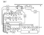
まず、図2に、本発明による、球面収差補正機能を備える光ディスク装置(光情報記録
装置)の全体構成例を示す。
First, FIG. 2 shows an example of the overall configuration of an optical disc apparatus (optical information recording apparatus) having a spherical aberration correction function according to the present invention.
(光学系の全体構成)
記録媒体である光ディスク8は、回転サーボ回路9によって回転速度が制御されたモー
タ10上に取付けられている。この媒体に対して、レーザ駆動回路11により駆動された
半導体レーザ12からの光を照射する。半導体レーザ12の光は、コリメートレンズ13
とビーム整形プリズム14を通過した後、反射鏡15により向きを変え、ディスク8へ向
けて導入される。反射鏡15にて反射された光は、偏向ビームスプリッタ16と、液晶収
差補正素子17と、λ/4板18を通過して、対物レンズ19により、ディスク8上に集
光照射される。対物レンズ19はアクチュエータ20上に取付けられており、焦点位置を
、トラッキングサーボ回路21の信号によってトラック方向に、焦点サーボ回路22の信
号によって焦点深度方向(フォーカス方向)に、それぞれ駆動できるようになっている。
また、この時、液晶収差補正素子17によって、ディスク8の基板厚誤差や対物レンズ1
9によって生じる球面収差が補正される。球面収差補正素子は、球面収差補正駆動回路2
3の制御電圧に応じて、光束の内周と外周で異なる屈折率分布を生じ、波面の進みと遅れ
を補償して、球面収差を補償する。球面収差が補正されることで、集光された光スポット
を、十分小さく絞ることができる。この光によって、ディスク8上に記録された微細なマ
ークパターンを読み取ったり、マークパターンを記録したりする。ディスク8によって照
射されたうち一部の光が反射され、再び対物レンズ19、λ/4板18、液晶収差補正素
子17を通過して、偏向ビームスプリッタ16によって、今度はシリンドリカルレンズ2
4の方向に分離される。分離された光は、シリンドリカルレンズ24、集光レンズ25を
通り、四分割光検出器26にて検出され、電気信号に変換される。この電気信号を、光電
流アンプ27で増幅し、この信号を元に加減算して、トラッキング誤差信号生成回路28
にてトラッキング誤差信号を、フォーカス誤差信号生成回路29にてフォーカス誤差信号
を、再生信号生成回路30にて再生信号を生成する。トラッキング誤差信号は、トラッキ
ング誤差信号振幅検出回路32によって、その信号振幅が検出され、出力される。また再
生信号は、再生信号振幅検出回路33にて、その信号振幅が検出され、出力される。これ
らの信号振幅の信号を元に、補正量生成回路34にて検出する。上記の構成は、球面収差
補正に関する部分(液晶収差補正素子17・球面収差補正駆動回路23・補正量生成回路
34)を除けば、一般的な光ディスク装置の構成と同じである。
(Overall configuration of optical system)
An
After passing through the
At this time, the liquid crystal
The spherical aberration caused by 9 is corrected. The spherical aberration correction element is a spherical aberration
In accordance with the control voltage 3, the refractive index distribution is different between the inner periphery and the outer periphery of the light beam, and the advance and delay of the wavefront are compensated to compensate for spherical aberration. By correcting the spherical aberration, the focused light spot can be narrowed down sufficiently. With this light, a fine mark pattern recorded on the
4 directions are separated. The separated light passes through the cylindrical lens 24 and the
The focus error
一方、得られたトラッキング誤差信号は、また、トラッキングサーボ回路21に供給さ
れ、対物レンズ19のトラック方向の位置を制御する。フォーカス誤差信号は、デフォー
カス量加算回路31によって、デフォーカス信号(焦点深度の補正量信号)が加算された
後、焦点サーボ回路22に供給され、対物レンズ19の焦点深度が制御される。再生信号
は、また、等価回路35、レベル検出回路36、同期クロック生成回路37を経て、複号
回路38にて記録された元のデジタル信号に変換される。これらの一連の回路は、主制御
回路39によって統括的に制御される。
On the other hand, the obtained tracking error signal is also supplied to the
補正量生成回路34では、トラッキング誤差信号振幅と、再生信号振幅を検知して、球
面収差の補正量信号と、デフォーカス信号を生成する。次に、この補正量生成回路34の
動作を説明する。
The correction amount generation circuit 34 detects the tracking error signal amplitude and the reproduction signal amplitude, and generates a spherical aberration correction amount signal and a defocus signal. Next, the operation of the correction amount generation circuit 34 will be described.
(球面収差の補正量生成回路)
補正量生成回路34は、トラッキング誤差信号振幅と、再生信号振幅の振舞いから、正
しい球面収差補正量と、デフォーカス量を生成する働きをしている。なお、デフォーカス
量とは、焦点深度の補正量であり、フォーカス誤差信号がゼロとなる点からどれだけずれ
た点へフォーカスを合わせるかという、焦点深度オフセット量のことである。以下では、
この焦点深度のオフセットのことを、デフォーカスと呼ぶことにする。
(Spherical aberration correction amount generation circuit)
The correction amount generation circuit 34 functions to generate a correct spherical aberration correction amount and a defocus amount from the behavior of the tracking error signal amplitude and the reproduction signal amplitude. The defocus amount is a depth of focus correction amount, which is a focus depth offset amount indicating how much the focus is shifted from the point where the focus error signal becomes zero. Below,
This offset of the focal depth is referred to as defocus.
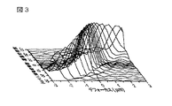
球面収差が生じた場合の、トラッキング誤差信号振幅と、再生信号振幅の振舞いを、図
3〜図4に示す。なおこれらは、光学計算により、理想的な状態を求めたものである。
FIGS. 3 to 4 show the behavior of the tracking error signal amplitude and the reproduction signal amplitude when spherical aberration occurs. These are the ideal states obtained by optical calculation.
図3は、トラッキング誤差信号振幅の、球面収差量と焦点深度に対する変化である。分
布は斜め方向に細長いピークを持つ、山脈状の分布となっている。これは、焦点深度が正
しく合っていない場合、球面収差が補正された正しい合焦点位置とは異なる所で、トラッ
キング誤差信号がピークとなることを示している。従って、正しい合焦点位置へ調整する
ためには、球面収差量と焦点深度を、両方同時に調整しながら、細長くなだらかなピーク
の頂上(トラッキング誤差信号振幅の最大値)へ向けて調整する必要があることを示して
いる。但し、トラッキング誤差信号振幅は、ディスクの回転で、場所によってムラが生じ
やすいため、この調整だけでは十分な調整ができない場合が多く生じる。また、ピーク頂
上の位置が、光学系の球面収差以外の他の収差(非点収差等)によって、正しい合焦点位
置からずれる場合がある。
FIG. 3 shows changes in the tracking error signal amplitude with respect to the spherical aberration amount and the focal depth. The distribution is a mountainous distribution with slender peaks in the diagonal direction. This indicates that when the focal depth is not correct, the tracking error signal peaks at a position different from the correct focal position where the spherical aberration is corrected. Therefore, in order to adjust to the correct in-focus position, it is necessary to adjust the spherical aberration amount and the depth of focus toward the peak of the slender and gentle peak (the maximum value of the tracking error signal amplitude) while simultaneously adjusting both the spherical aberration amount and the focal depth. It is shown that. However, since the tracking error signal amplitude is likely to be uneven depending on the location due to the rotation of the disk, there are many cases where sufficient adjustment cannot be made by this adjustment alone. In addition, the peak peak position may deviate from the correct in-focus position due to other aberrations (such as astigmatism) other than the spherical aberration of the optical system.
一方、図4は、再生信号振幅の、球面収差量と焦点深度に対する変化である。分布は中
央にやや鋭いピークを持ち、周囲に多くの小さな偽ピークがひしめく分布となっている。
中央ピークは、斜めではないことから、ピーク中央付近では、正しい合焦点位置を探しや
すい。従って、正しい合焦点位置へ調整するためには、球面収差量と焦点深度を交互に調
整しながら、ピークの頂上(再生信号振幅の最大値)へ向けて調整ればよいことが分かる
。ピーク頂上の位置は、他の収差(非点収差等)があっても、比較的正しい合焦点位置に
安定している。但し、未記録ディスク(未初期化・未フォーマットのディスク)では、ま
だマークが書き込まれていないため、この再生信号振幅が検出できない。
On the other hand, FIG. 4 shows changes in the reproduction signal amplitude with respect to the spherical aberration amount and the focal depth. The distribution has a slightly sharp peak in the center and many small false peaks around it.
Since the central peak is not diagonal, it is easy to find the correct in-focus position near the center of the peak. Therefore, in order to adjust to the correct in-focus position, it is only necessary to adjust toward the peak peak (maximum value of the reproduction signal amplitude) while alternately adjusting the spherical aberration amount and the focal depth. The peak peak position is stable at a relatively correct in-focus position even with other aberrations (such as astigmatism). However, in the case of an unrecorded disc (uninitialized / unformatted disc), the mark has not yet been written, so that the reproduction signal amplitude cannot be detected.
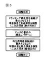
従って、未記録ディスクでも正しく球面収差が調整できるためには、まず図3のトラッ
キング誤差信号振幅の最大値を探して、球面収差量と焦点深度を、両方同時に調整し、大
まかに調整できたところで、再生信号の元となるマークを書込み、そのマークの再生信号
を利用して、図4の再生信号振幅の最大値を探して、球面収差量と焦点深度を調整すると
いう、二段階の調整が必要となる。この手順を図5(フローチャート)に示す。
Therefore, in order to adjust the spherical aberration correctly even on an unrecorded disc, first, the maximum value of the tracking error signal amplitude in FIG. 3 is searched, and both the spherical aberration amount and the focal depth are adjusted at the same time. This is a two-stage adjustment that writes the mark that is the source of the reproduction signal, uses the reproduction signal of that mark, finds the maximum value of the reproduction signal amplitude in FIG. 4, and adjusts the spherical aberration amount and the depth of focus. Necessary. This procedure is shown in FIG.
主制御回路39からの信号に基いて、上記の手順で二段階の調整を行うのが、補正量生
成回路34である。焦点深度の変化量として、デフォーカス信号を出力し、球面収差の補
正量信号は、球面収差補正駆動回路23へ出力する。球面収差の補正量信号と、デフォー
カス信号を、上記の手順によって、トラッキング誤差信号振幅を最大化するように、両方
同時に調整し、次に、マークの記録後に、再生信号振幅を最大化するよう、交互に調整す
ることによって、球面収差が補正された正しい合焦点位置へ光学系を調整し、全体として
球面収差が正しく補正制御される。
Based on the signal from the
なお、球面収差の補正量信号とデフォーカス信号の調整法としては、例えば二次元探索
の手法を用いればよい。本調整における二次元探索の手順の例については、次以降の実施
例にて述べる。
As a method for adjusting the spherical aberration correction amount signal and the defocus signal, for example, a two-dimensional search method may be used. An example of a two-dimensional search procedure in this adjustment will be described in the following examples.
(効果・補足)
本手法では、記録媒体(光ディスク8)として、未記録状態でマーク(またはピット)
が形成されていない媒体を用いることができるため、予め記録マーク(ピット)の形成が
不要であり、低コストであるという利点がある。
(Effect / Supplement)
In this method, a mark (or pit) is recorded in an unrecorded state as a recording medium (optical disc 8).
Therefore, there is an advantage that the formation of recording marks (pits) is unnecessary and the cost is low.
また、本手法では、球面収差補正以外の光学系の構成は従来と同様であることから、こ
れらの光ヘッドにおいて、従来光学系と同様の部品や回路をそのまま使えるため、低コス
トであるという利点がある。
Also, with this method, the configuration of the optical system other than spherical aberration correction is the same as that of the conventional one. Therefore, in these optical heads, the same parts and circuits as those of the conventional optical system can be used as they are, so that the cost is low. There is.
また、トラッキング誤差信号振幅によって粗調整することで、再生信号振幅の中央ピー
ク付近に予め合わせておくことができるため、再生信号振幅の最大値探索時に、偽ピーク
に収束することを防ぐことができため、調整が高信頼化できるという利点がある。
In addition, by roughly adjusting the tracking error signal amplitude, it is possible to adjust to the vicinity of the center peak of the reproduction signal amplitude in advance, so that it is possible to prevent convergence to a false peak when searching for the maximum value of the reproduction signal amplitude. Therefore, there is an advantage that adjustment can be made highly reliable.
また、球面収差以外の他の収差があった場合でも、再生信号振幅によって再調整するた
めに、他収差によるトラッキング誤差信号振幅のピーク頂上の位置ずれがあった場合でも
、正しい合焦点位置へ光学系を自動調整でき、調整が高信頼化できるという利点がある。
Even if there are other aberrations than spherical aberration, the optical signal is adjusted to the correct in-focus position even if there is a misalignment of the peak peak of the tracking error signal amplitude due to other aberrations because of readjustment with the reproduction signal amplitude. There is an advantage that the system can be adjusted automatically and the adjustment can be made highly reliable.
即ち、書換え型の光記録媒体に対し、トラッキング誤差信号振幅を最大化するよう調整
した後に、マークを記録し、そのマークの再生信号振幅を最大化するよう調整する、とい
う二段階の手順で調整することで、低コストに、高信頼な自動調整ができる。
That is, for a rewritable optical recording medium, the adjustment is made in a two-step procedure in which the tracking error signal amplitude is adjusted to be maximized and then the mark is recorded and the reproduction signal amplitude of the mark is adjusted to be maximized. By doing so, highly reliable automatic adjustment can be performed at low cost.
なお、上記の四分割光検出器26に、トラッキング誤差信号検出用の光検出器面を追加
した、差動プッシュプル方式で、本方法を用いることもできる。差動プッシュプル方式で
は、前記トラッキング誤差信号に代えて、トラッキング誤差信号と追加光検出器面の信号
の和差により生成される差動プッシュプル信号を用いる。これまでに述べたトラッキング
誤差信号の特性は、差動プッシュプル信号でも同様である。従って、本方法は、差動プッ
シュプル方式でも同様に使用可能である。
In addition, this method can also be used by the differential push pull system which added the photodetector surface for tracking error signal detection to said
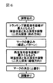
また、調整のために記録した前記マークは、前記調整の後に上書きまたは消去するとよ
い。この手順を図6(フローチャート)に示す。この様にすることで、調整時の一時的な
マークの書込みによる情報書換えの不具合をなくすことができる。
The mark recorded for adjustment may be overwritten or erased after the adjustment. This procedure is shown in FIG. 6 (flow chart). By doing so, it is possible to eliminate the problem of information rewriting due to temporary writing of marks during adjustment.
また、上記には、光ディスクを想定した、回転型の記録媒体を用いた例を示したが、カ
ード型のような、非回転型の記録媒体に対する情報記録再生の場合についても、上記手法
と効果は同様である。非回転型記録媒体の場合は、トラッキング誤差信号とは、データが
(記録媒体上で)一線上に整列されて記録/再生される時、上記整列された一線の中心か
らのずれ量を得る信号とすればよい。カード型媒体上に、光ディスク同様に記録膜上に溝
構造を形成すれば、上記回転型光ディスクと同様のトラッキング誤差信号が得られる。図
に示したヘッドおよび回路の構成はそのまま適用できる。
In addition, the example using a rotation type recording medium assuming an optical disk has been described above. However, the above method and effect can be applied to the case of information recording / reproduction with respect to a non-rotation type recording medium such as a card type. Is the same. In the case of a non-rotating recording medium, the tracking error signal is a signal for obtaining a deviation amount from the center of the aligned line when data is recorded / reproduced aligned on the line (on the recording medium). And it is sufficient. If a groove structure is formed on the recording film on the card-type medium in the same manner as the optical disk, a tracking error signal similar to that on the rotating optical disk can be obtained. The configuration of the head and circuit shown in the figure can be applied as it is.
また、球面収差の補正手段として、液晶収差補正素子17を用いた例を上記には示した
が、液晶補正素子に代えて、レンズの組合せを用いることもできる。図7は、球面収差の
補正手段として、可動凸レンズ6と凹レンズ7の組合せを用いた場合の構成例である。こ
の場合、可動凸レンズ6を球面収差補正駆動回路23の出力に応じ比例して変位させるこ
とで、基板厚の違いにより生じる球面収差を、レンズ間距離の変化により生じる実効的な
焦点距離の変化を利用して、焦点位置の補正という形で補償できる。なお、この場合でも
、上記の球面収差と焦点深度の調整手順は、変更なくそのまま適用できる。
Further, although an example using the liquid crystal
また、上記では、未記録のディスクでも適用で切る球面収差補正の手順を示したが、す
でに記録済(初期化済)のディスクに対して球面収差調整を行う場合は、すでに記録され
ているマークの再生信号が検出できるため、直接、再生信号振幅の調整から始めることが
できる。従って、図1(フローチャート)の手順のように、調整の最初に、再生信号を検
出し、記録済か未記録であるかを判定することによって、トラッキング誤差信号振幅の調
整から開始するか、再生信号振幅の調整から開始するか、処理を振り分けることで、記録
済のディスクに対する調整時間を短縮することができ、かつどちらのディスクに対しても
正しい球面収差調整ができる。本方法は、二回目以降に使用するディスクに対する球面収
差の調整時間を短縮できるという利点がある。
In the above description, the spherical aberration correction procedure for cutting an unrecorded disc is shown. However, when performing spherical aberration adjustment on a disc that has already been recorded (initialized), a mark that has already been recorded. Therefore, it is possible to directly start adjustment of the reproduction signal amplitude. Therefore, as in the procedure of FIG. 1 (flow chart), at the beginning of the adjustment, the reproduction signal is detected and it is determined whether it is recorded or unrecorded. By starting from the adjustment of the signal amplitude or by allocating the processing, the adjustment time for the recorded disk can be shortened, and correct spherical aberration adjustment can be performed for both disks. This method has an advantage that the spherical aberration adjustment time for the disk used for the second time and thereafter can be shortened.
二次元探索の方法
次に、本発明による、球面収差/焦点深度調整の二次元探索の手順の例について、図8
〜図15を用いて説明する。
(トラッキング誤差信号振幅の二次元探索方法)
以下、図8〜図11を用いて、トラッキング誤差信号振幅の最大化探索の手順を説明す
る。
Method for Two-Dimensional Search Next, an example of a procedure for a two-dimensional search for spherical aberration / focus depth adjustment according to the present invention will be described with reference to FIG.
Description will be made with reference to FIG.
(Two-dimensional search method for tracking error signal amplitude)
Hereinafter, the procedure of the search for maximizing the tracking error signal amplitude will be described with reference to FIGS.
まず、図8に、先に図3に示したトラッキング誤差信号振幅の分布を、中央付近を拡大
して等高線図としたものを示す。なお、先に示した図3とは球面収差量の軸の正負を反転
しているため、みかけの傾きが逆になっている。
First, FIG. 8 shows a contour map obtained by enlarging the vicinity of the center of the distribution of the tracking error signal amplitude shown in FIG. In addition, since the positive / negative of the axis | shaft of spherical aberration amount is reversed with FIG. 3 shown previously, the apparent inclination is reverse.
実施例1にて述べたように、トラッキング誤差信号振幅の分布は、球面収差量と焦点深
度に対し、斜め方向に細長いピークを持つ、山脈状の分布となっている。
分布は斜め方向に細長いピークを持つ、山脈状の分布となっている。従って、球面収差量
に応じ、ピークが最大値をとる焦点深度が異なっている。このため、ピークの探索時には
、球面収差量を変化するたびに、焦点深度を変えて、斜め方向に最大となる点を探して比
較しなければならない。
As described in the first embodiment, the distribution of the tracking error signal amplitude is a mountain-shaped distribution having an elongated peak in an oblique direction with respect to the spherical aberration amount and the focal depth.
The distribution is a mountainous distribution with slender peaks in the diagonal direction. Therefore, the depth of focus at which the peak takes a maximum value varies depending on the amount of spherical aberration. For this reason, when searching for a peak, every time the amount of spherical aberration is changed, the depth of focus must be changed to find and compare the maximum point in the oblique direction.
例として、図の白丸(a)の位置を探索の始点とすると、最初に球面収差量を変化させ
て、トラッキング誤差信号振幅が最大となる(b)の点を探す。(b)はすでに山脈の峰
の上にあるため、ここから焦点深度のみを調節すると、左右(b1)(b2)のどちらに
変化しても、(b)よりもトラッキング誤差信号振幅が小さくなる。従って、(b)より
もトラッキング誤差信号振幅が大きくなる点を見つけるためは、(c)(c')のように
斜め方向に動く必要がある。(c)からさらに振幅が大きくなる(d)、(d)から(e
)を見つけて、振幅の最大値となるピーク頂上を見つける。
このように、トラッキング誤差信号振幅の二次元探索で、正しく探索するためには、基板
厚誤差と焦点深度について、二次元的に斜め方向へ、信号振幅のより大きな方を探索する
手順を含むことが必要となる。この探索では、図8の矢印のように、上記二次元プロット
上で、(b)→(c)、(d)→(e)のように、斜め方向に動く軌跡となる。これを、
斜め方向に探索する、と呼ぶことにする。
As an example, if the position of the white circle (a) in the figure is the starting point of the search, the spherical aberration amount is first changed to search for the point (b) where the tracking error signal amplitude is maximum. Since (b) is already on the peak of the mountain range, if only the depth of focus is adjusted from here, the tracking error signal amplitude will be smaller than (b) regardless of whether it changes to left or right (b1) or (b2). . Accordingly, in order to find a point where the tracking error signal amplitude is larger than that in (b), it is necessary to move in an oblique direction as in (c) and (c ′). The amplitude further increases from (c) (d), (d) to (e
) To find the peak peak with the maximum amplitude.
As described above, in order to search correctly in the two-dimensional search of the tracking error signal amplitude, a procedure for searching for the larger signal amplitude in the two-dimensional oblique direction with respect to the substrate thickness error and the focal depth is included. Is required. In this search, as shown by the arrows in FIG. 8, on the two-dimensional plot, the trajectory moves in an oblique direction as (b) → (c), (d) → (e). this,
This is called searching in an oblique direction.
トラッキング誤差信号振幅の検出では、通常、ディスクの一回転内で、回転角度によっ
て、部分的にディスクの反りがあるなどの原因によって、焦点の合う部分と合いにくい部
分ができ、一周内のトラッキング誤差信号振幅にムラがあることが多いことから、一周全
体を正しく検出できるよう、一回の振幅の検出に、ディスクの回転「一周」分待つことが
多い。このため、検出点数が多いほど、探索(調整)に時間がかかる。従って、上記の様
に、一回の検出で、直接斜め方向を探索することで、探索にかかる時間を短縮できる効果
は大きい。
When detecting the tracking error signal amplitude, it is usually difficult to match the in-focus part due to the disk's warping, etc., depending on the rotation angle within one rotation of the disk. Since the signal amplitude is often uneven, it is often necessary to wait for the rotation of the disc for one rotation so that the entire amplitude can be detected correctly. For this reason, the search (adjustment) takes time as the number of detection points increases. Therefore, as described above, by searching directly in an oblique direction with one detection, the effect of shortening the search time is great.
なお、上記におけるトラッキング誤差信号振幅の最大化とは、完全に最大値でなくとも
よい。図8の中央ピークの強度(十字の中心での強度)は0.626(任意強度)である
が、図8より分かる通り、振幅0.60以上に調整できていれば、正しい合焦点位置から
、残球面収差量8μm(基板厚換算)以内、デフォーカス誤差±0.7μm以内に収めら
れる。トラッキング誤差信号振幅による調整で、この範囲に誤差を収められれば、後の再
生信号振幅の分布において、中央ピークの裾野の中に入っており、再生信号振幅の最大値
探索で正しいピーク頂上に収束できる。即ち、完全に最大値でなくとも、最大値の96%
以上に調整できていれば、本願明細書に記載した期待の効果が得られる。これを含めて、
振幅を増加させるよう調整することを、本願明細書で「最大化」と呼ぶことにする。
Note that the above-described maximization of the tracking error signal amplitude may not be a completely maximum value. The intensity of the central peak in FIG. 8 (intensity at the center of the cross) is 0.626 (arbitrary intensity). However, as can be seen from FIG. The residual spherical aberration amount is within 8 μm (substrate thickness conversion) and the defocus error is within ± 0.7 μm. If the error can be kept within this range by adjusting the tracking error signal amplitude, it will be in the bottom of the central peak in the distribution of the playback signal amplitude later and converge to the correct peak peak by searching for the maximum value of the playback signal amplitude. it can. That is, 96% of the maximum value even if it is not completely maximum
If the adjustment can be made as described above, the expected effect described in the present specification can be obtained. Including this,
Adjustment to increase the amplitude will be referred to herein as “maximization”.
探索時、斜め方向の傾きが、理想的な傾きからずれた場合は、図9より、傾きの比の値
が、正しい比の値の±60%の範囲に収まれば、収束速度は4方向探索の倍以上得られる
。また、理想的な傾きから、±25%の範囲に収まれば、収束速度は最速時(±0%時)
の半分以上は保てる。従って、斜め方向の傾きとしては、正しい比の値から、これらの範
囲に収まっていることが望ましい。
If the inclination in the oblique direction deviates from the ideal inclination during the search, the convergence speed is a four-way search if the inclination ratio value is within ± 60% of the correct ratio value from FIG. More than twice. Also, if it is within ± 25% of the ideal slope, the convergence speed is the fastest (± 0%).
I can keep more than half of it. Therefore, it is desirable that the inclination in the oblique direction be within these ranges from the correct ratio value.
理想的には、この斜め方向の傾きは、例えば、次の比例式より得ることができる。 Ideally, the inclination in the oblique direction can be obtained from the following proportional expression, for example.
但し、Δzはディフォーカス量、Δtは基板厚誤差、nは基板の屈折率、NAはレンズの
開口数である。これは、基板厚誤差Δtの生じる球面収差による、開口数NAに相当する
瞳半径までの均一な光分布を仮定した場合の、近軸像点(ガウス像点)と理想像点の差と
してΔzを求めたものである。これは、n=1.6、NA=0.85の時、
Where Δz is the defocus amount, Δt is the substrate thickness error, n is the refractive index of the substrate, and NA is the numerical aperture of the lens. This is the difference between the paraxial image point (Gauss image point) and the ideal image point, Δz, assuming a uniform light distribution up to the pupil radius corresponding to the numerical aperture NA due to the spherical aberration that causes the substrate thickness error Δt. Is what we asked for. This is when n = 1.6 and NA = 0.85.
となり、一定の係数で比例する、定数比の関係となる。基板厚誤差14.5μmに対し、
焦点深度1μmの比率で、相当する球面収差量とディフォーカス量を、同時に変化させて
補正駆動すれば、ほぼトラッキング誤差信号振幅の最大となる山脈状の峰上を外れること
なく移動できることになる。ただし、上記の式が成立つのは、レンズに入射される光束の
光量分布が均一な場合であり、分布が不均一な場合には、実質的な開口数(NA)の値が
(主に)小さくなるために、値が変化する。また、トラック間隔と光スポットの分解能の
比によっても影響を受ける。このため、例えば、実際の光ヘッドでは、上記の比の値(1
4.5)が、実際には25付近と、倍半分近い値まで変化する場合がある。従って、上記
の数式より得られる値は参考値であり、実際の傾きの比の値には、個々に設計された光ヘ
ッドに対し、実測で値を求めたものを用いる。
Thus, a constant ratio relationship proportional to a constant coefficient is obtained. For substrate thickness error of 14.5μm
If the corresponding spherical aberration amount and the defocus amount are changed at the same time at the ratio of the focal depth of 1 μm and the correction driving is performed, the movement can be made without departing from the mountain-shaped peak where the tracking error signal amplitude is maximum. However, the above formula is established when the light quantity distribution of the light beam incident on the lens is uniform. When the distribution is non-uniform, the substantial numerical aperture (NA) value is (mainly). The value changes to be smaller. It is also affected by the ratio between the track spacing and the light spot resolution. Therefore, for example, in an actual optical head, the ratio value (1
4.5) may actually change to a value close to 25 and nearly half the value. Therefore, the value obtained from the above formula is a reference value, and the value obtained by actual measurement with respect to the individually designed optical head is used as the actual inclination ratio value.
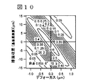
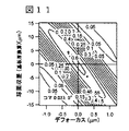
次に、球面収差以外の収差が、光学系の部品誤差や位置調整誤差によって発生した場合
の、トラッキング誤差信号振幅の分布の等高線図を、図10〜図11に示す。図10は非
点収差、図11はコマ収差が生じた場合の分布であるが、非点収差が生じた場合に、分布
のピークの中心が、左側にずれており、ピーク頂上(トラッキング誤差信号振幅の最大点
)に調整しても、正しい合焦点位置に調整できない場合があることが分かる。従って、次
に述べるような再生信号振幅による調整が必要になることが分かる。
Next, FIG. 10 to FIG. 11 show contour maps of the distribution of the tracking error signal amplitude when aberrations other than spherical aberration are caused by component errors or position adjustment errors of the optical system. FIG. 10 shows the distribution when astigmatism occurs, and FIG. 11 shows the distribution when coma occurs. When astigmatism occurs, the center of the peak of the distribution is shifted to the left side, and the peak peak (tracking error signal) It can be seen that even if the amplitude is adjusted to the maximum point, it may not be adjusted to the correct in-focus position. Therefore, it can be seen that adjustment based on the reproduction signal amplitude as described below is required.
本手法では、球面収差調整の第一調整である、トラッキング誤差信号振幅の最適点の探
索において、調整を高速化することができるため、ローディング直後または初期化時の待
ち時間を短縮できるという利点がある。
(再生信号信号振幅の二次元探索方法)
次に、図12〜図15を用いて、トラッキング誤差信号振幅の最大化探索の手順を説明
する。
In this method, the search for the optimum point of the tracking error signal amplitude, which is the first adjustment of the spherical aberration adjustment, can be speeded up, so that the waiting time immediately after loading or at the time of initialization can be shortened. is there.
(2D search method for playback signal amplitude)
Next, a procedure for maximizing the tracking error signal amplitude will be described with reference to FIGS.
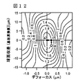
まず、図12に、先に図4に示した再生信号振幅の分布を、中央付近を拡大して等高線
図としたものを示す。
First, FIG. 12 shows a contour map obtained by enlarging the vicinity of the center of the reproduction signal amplitude distribution shown in FIG.
実施例1にて述べたように、再生信号振幅の分布は、球面収差量と焦点深度に対し、中
央にやや鋭いピークを持ち、周囲に多数の小さな偽ピークがある。中央ピークは、斜めで
はないことから、球面収差量と焦点深度を独立して交互に変化させて調整することで、正
しい合焦点位置(中央ピークの頂上)が探せる。
As described in the first embodiment, the reproduction signal amplitude distribution has a slightly sharp peak in the center with respect to the spherical aberration amount and the depth of focus, and a large number of small false peaks in the periphery. Since the central peak is not oblique, the correct focal point position (the top of the central peak) can be found by adjusting the spherical aberration amount and the focal depth independently and alternately.
例として、図の白丸(e)の位置を始点として探索すると、最初に球面収差量を変化さ
せて、再生信号振幅が最大となる(f)の点を探す。ここから焦点深度のみを調節すると
、よりピーク頂上に近い(g)の点が、より再生信号振幅が大きな点として見つかる。こ
のように、探索の始点が中央ピーク付近に合っていれば、より再生信号振幅が大きくなる
ように、球面収差量と焦点深度を交互に変化させることで、振幅が最大となるピークの頂
上へ調節することができる。従って、正しい合焦点位置へ調整するためには、球面収差量
と焦点深度を交互に調整しながら、ピークの頂上(再生信号振幅の最大値)へ向けて調整
ればよいことが分かる。このように、再生信号振幅の二次元探索では、基板厚誤差と焦点
深度について、単純に交互に調整することで、ほぼ最速の探索ができる。このような交互
の調整は、図4の矢印のように、上記二次元プロット上で、縦横に動く軌跡となる。これ
を、縦横方向に探索する、と呼ぶことにする。
As an example, when searching with the position of the white circle (e) in the figure as the starting point, the spherical aberration amount is first changed to search for the point (f) where the reproduction signal amplitude is maximum. If only the depth of focus is adjusted from here, the point (g) closer to the peak top is found as a point having a larger reproduction signal amplitude. Thus, if the starting point of the search is in the vicinity of the central peak, the spherical aberration amount and the focal depth are alternately changed so that the reproduction signal amplitude becomes larger, so that the peak at which the amplitude becomes maximum is reached. Can be adjusted. Therefore, in order to adjust to the correct in-focus position, it is only necessary to adjust toward the peak peak (maximum value of the reproduction signal amplitude) while alternately adjusting the spherical aberration amount and the focal depth. Thus, in the two-dimensional search of the reproduction signal amplitude, the fastest search can be performed by simply alternately adjusting the substrate thickness error and the focal depth. Such alternate adjustment becomes a trajectory that moves vertically and horizontally on the two-dimensional plot, as indicated by the arrows in FIG. This is called searching in the vertical and horizontal directions.
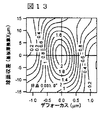
次に、球面収差以外の収差が、光学系の部品誤差や位置調整誤差によって発生した場合
の、再生信号振幅の分布の等高線図を、図13〜図14に示す。図13は、非点収差、図
14はコマ収差が生じた場合の分布であるが、今度は、これらの収差があっても、分布の
ピークの中心は、グラフの中心にほぼ一致しており、ピーク頂上(再生信号振幅の最大点
)に調整することで、正しい合焦点位置に調整できることが分かる。従って、再生信号振
幅で微調整すれば、トラッキング誤差信号振幅による粗調整で生じていた誤差を正しく修
正できることが分かる。
Next, FIG. 13 to FIG. 14 show contour maps of the reproduction signal amplitude distribution in the case where aberrations other than spherical aberration occur due to component errors or position adjustment errors of the optical system. FIG. 13 shows the distribution when astigmatism occurs, and FIG. 14 shows the distribution when coma aberration occurs. Now, even with these aberrations, the center of the peak of the distribution almost coincides with the center of the graph. It can be seen that adjustment to the peak peak (the maximum point of the reproduction signal amplitude) enables adjustment to the correct in-focus position. Accordingly, it can be seen that if the fine adjustment is performed with the reproduction signal amplitude, the error caused by the coarse adjustment by the tracking error signal amplitude can be corrected correctly.
次に、この再生信号を得るために書込むマークのパターンの周期を変化させた場合の、
再生信号振幅の分布の等高線図を、図15(a)〜(d)に示す。これらの図は、マーク
部とスペース部(マークを記録しない部分)の長さの比を1:1とし、繰返しパターンと
して記録した場合の再生信号の振幅で、マーク周期(マーク部とスペース部の長さの和)
を図15(a)(b)(c)(d)のように、トラック間隔の1.5倍、2倍、4倍、6
倍と変化させた場合の分布である。トラック間隔は、通常、光スポット径よりも1〜2割
小さい値とするのが、記録密度的に効率が良く、一般的である。従って、一般の光ディス
ク装置または光記録媒体では、データ領域のトラック間隔は、光スポットの分解能を反映
した値となっている。
Next, when changing the period of the mark pattern to be written to obtain this playback signal,
Contour diagrams of the distribution of the reproduction signal amplitude are shown in FIGS. In these figures, the ratio of the length of the mark portion and the space portion (the portion where no mark is recorded) is 1: 1, and the amplitude of the reproduction signal when recorded as a repetitive pattern indicates the mark period (the mark portion and the space portion). Sum of length)
15 (a) (b) (c) (d), 1.5 times, 2 times, 4 times, 6 times the track interval.
This is the distribution when changed by a factor of two. In general, the track interval is set to a value smaller by 10 to 20% than the diameter of the light spot. Therefore, in a general optical disc apparatus or optical recording medium, the track interval in the data area is a value reflecting the resolution of the light spot.
マーク周期の短い図15(a)では、分布がやや斜めとなっているため、トラッキング
誤差信号振幅の二次元探索と同様の理由で、球面収差量と焦点深度を交互に調整する、上
記の調整の手順では、若干探索速度が落ちる。一方、マーク周期の長い、図15(d)で
は、分布のピーク中心(頂上:最大点)が、グラフの中心よりも、若干右下側にずれてい
る(正しい合焦点位置からずれている)ことが分かる。従って、再生信号振幅の最大値を
探索して、正しい合焦点位置を探す場合、記録するマークの長さには、トラック間隔の2
〜4倍程度が適していることが分かる。また、この付近において、ピーク周囲の線の密度
が高く、球面収差量と焦点深度の変化に対する、再生信号振幅の変化も大きいことから、
調整感度が高く、調整がやりやすくなることが分かる。最も良いのは、2倍と4倍の中間
にあたる、3倍付近であった。
In FIG. 15A with a short mark period, since the distribution is slightly inclined, the spherical aberration amount and the depth of focus are adjusted alternately for the same reason as the two-dimensional search of the tracking error signal amplitude. In this procedure, the search speed is slightly reduced. On the other hand, in FIG. 15D with a long mark period, the distribution peak center (top: maximum point) is slightly shifted to the lower right side of the graph center (shifted from the correct in-focus position). I understand that. Therefore, when searching for the maximum value of the reproduction signal amplitude to find the correct in-focus position, the length of the mark to be recorded includes 2 of the track interval.
It can be seen that about 4 times is suitable. Also, in this vicinity, the density of the line around the peak is high, and the change in the reproduction signal amplitude with respect to the change in the spherical aberration amount and the depth of focus is large.
It can be seen that the adjustment sensitivity is high and adjustment is easy. The best was around 3 times, halfway between 2 times and 4 times.
従って、記録するマークの周期を適した長さに設定し、記録するマークのパターンとし
て、データ領域のトラック間隔の2倍〜4倍のマーク間隔となるマークの繰返しパターン
を用いることで、再生信号振幅の最大化探索で、正しい合焦点位置へ簡易に調整できる。
これにより、調整感度が高くなり、ノイズ等の影響を受けにくくなることによって、調整
のための制御の仕組みを低コスト化できるという利点がある。
Therefore, by setting the period of the mark to be recorded to an appropriate length and using a repeated pattern of marks having a mark interval twice to four times the track interval of the data area as a pattern of the mark to be recorded, It can be easily adjusted to the correct in-focus position by searching for the maximum amplitude.
As a result, the adjustment sensitivity becomes high and is less susceptible to noise and the like, so that there is an advantage that the cost of the control mechanism for adjustment can be reduced.
なお、上記において、トラック間隔を、マークの長さの基準と考えたのは、トラック間
隔が、通常、光スポット径を反映したものとなっているため、光スポットの分解能の基準
の一つとして見ることができることによる。
In the above, the track interval is considered as a reference for the length of the mark, because the track interval usually reflects the diameter of the light spot. Depending on what you can see.
以上のように、球面収差と焦点深度の調整においては、図8〜図15に示したような焦
点深度と球面収差補正量の二次元プロット上で、トラッキング誤差信号振幅の最大値探索
では斜め方向に探索を行い、再生信号振幅の最大値探索では縦横方向の探索に切り替える
ことで、共に探索の時間を短く抑えることができ、かつ調整の信頼性が確保できる。
As described above, in the adjustment of the spherical aberration and the depth of focus, in the two-dimensional plot of the depth of focus and the spherical aberration correction amount as shown in FIGS. In the search for the maximum value of the reproduction signal amplitude, the search time is switched to the vertical and horizontal directions, so that the search time can be kept short and the adjustment reliability can be ensured.
(効果・補足)
以上のように、トラッキング誤差信号振幅の分布と、再生信号振幅の分布には、形状の
違いがあるために、両者の最大値探索において、探索法を切り替えることが、調整の高速
化につながる。前記球面収差と焦点深度の調整において、焦点深度と球面収差補正量の二
次元プロット上で、トラッキング誤差信号振幅の最大値探索で斜め方向(二軸に対し斜め
となる方向)に探索を行い、再生信号振幅の最大値探索で縦横方向(二軸と垂直/平行な
方向)に探索することで、全体として確実で高速な光学系の調整ができる。
(Effect / Supplement)
As described above, since there is a difference in the shape of the tracking error signal amplitude distribution and the reproduction signal amplitude distribution, switching the search method in the maximum value search of both leads to an increase in the speed of adjustment. In the adjustment of the spherical aberration and the depth of focus, on the two-dimensional plot of the depth of focus and the spherical aberration correction amount, a search is performed in an oblique direction (direction oblique to the two axes) by searching for the maximum value of the tracking error signal amplitude. By searching for the maximum value of the reproduction signal amplitude in the vertical and horizontal directions (directions perpendicular / parallel to the two axes), the entire optical system can be adjusted reliably and at high speed.
本手法では、未記録の記録媒体に対応し、球面収差調整を高信頼化した上で、全体とし
ての調整を高速化することができる。これによって、球面収差量と焦点深度を、効率よく
調節することができ、光軸の調整に要する時間を大幅に短縮できるという利点がある。ま
た、それによって、ローディング直後または初期化時の待ち時間を短縮できるという利点
がある。)
なお、球面収差と焦点深度に加えて、チルト(光ヘッドと記録媒体の相対傾き)の調整
が加わる場合があり、その場合、チルト(二自由度)の調整を加えた三次元/四次元の探
索となる構成も可能だが、その場合は、例えば四自由度のうち、球面収差量と焦点深度の
二自由度を抽出して二次元プロットとした場合に、上記と同様、球面収差量と焦点深度に
ついて、斜め方向、縦横方向の探索を行えばよい。
According to this method, it is possible to cope with an unrecorded recording medium, and to increase the speed of the adjustment as a whole while making the spherical aberration adjustment highly reliable. As a result, the amount of spherical aberration and the depth of focus can be adjusted efficiently, and the time required for adjusting the optical axis can be greatly reduced. This also has the advantage that the waiting time immediately after loading or initialization can be shortened. )
Note that in addition to spherical aberration and depth of focus, tilt (relative tilt between the optical head and the recording medium) may be adjusted. In this case, three-dimensional / four-dimensional adjustment with tilt (two degrees of freedom) is added. A search configuration is possible, but in that case, for example, when two degrees of freedom of spherical aberration and depth of focus are extracted from the four degrees of freedom to obtain a two-dimensional plot, the amount of spherical aberration and the focus are the same as above. The depth may be searched in the diagonal direction and the vertical and horizontal directions.
また、本手法では、ディスク光学系の非点収差によらず、正しい最適点へ球面収差調整
できるため、媒体として、収差の生じやすい厚いプラスチック層(カバー層、基板層)を
持つものが利用できる。収差によらず、安定した光スポットが得られるため、より高密度
に記録できるという利点がある。
(実施例3:内挿値による球面収差調整)
次に、図2と、図16〜図21を用いて、記録媒体の情報記録場所によって媒体の透明
層の厚さが変化した場合の球面収差補正を備えた光情報記録装置の構成例を説明する。
In addition, in this method, spherical aberration can be adjusted to the correct optimum point regardless of the astigmatism of the disk optical system, so that a medium having a thick plastic layer (cover layer, substrate layer) that easily causes aberration can be used. . Since a stable light spot can be obtained regardless of aberration, there is an advantage that recording can be performed with higher density.
(Example 3: spherical aberration adjustment by interpolation value)
Next, with reference to FIG. 2 and FIGS. 16 to 21, a configuration example of an optical information recording apparatus provided with spherical aberration correction when the thickness of the transparent layer of the medium changes depending on the information recording location of the recording medium will be described. To do.
(記録層一層のみ又は同一記録層内の補正)
まず、図16〜図17を用いて、記録層が一層、または同一記録層内の、記録媒体の透
明層の厚さムラによる球面収差を補正する光情報記録装置の構成例を説明する。
(Correction in only one recording layer or in the same recording layer)
First, a configuration example of an optical information recording apparatus that corrects spherical aberration due to thickness unevenness of a transparent layer of a recording medium in one recording layer or in the same recording layer will be described with reference to FIGS.
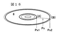
図16は、記録媒体として、記録層が一層のみの、回転型の記録媒体を用いた場合の、
球面収差の調整方法である。図17(フローチャート)は、その調整の手順である。内周
側(A)と、外周側(B)の点における、球面収差量と、焦点深度を、実施例1〜2に記
載の方法によって測定する。A点とB点としては、ディスクのデータ記録領域の最内周付
近と、最外周付近を取るのが理想的である。A点で得た球面収差量をSA1、焦点深度を
DF1、同様に、B点で得た球面収差量をSA2、焦点深度をDF2とする。
FIG. 16 shows a case where a rotary recording medium having only one recording layer is used as the recording medium.
This is a method for adjusting spherical aberration. FIG. 17 (flow chart) shows the adjustment procedure. The spherical aberration amount and the depth of focus at the points on the inner peripheral side (A) and the outer peripheral side (B) are measured by the methods described in Examples 1-2. Ideally, the points A and B should be near the innermost circumference and the outermost circumference of the data recording area of the disc. The amount of spherical aberration obtained at point A is SA1, the depth of focus is DF1, and similarly, the amount of spherical aberration obtained at point B is SA2, and the depth of focus is DF2.
この時、記録媒体(ディスク)上の任意の位置Pxにおける。球面収差量SAxを、 At this time, at an arbitrary position Px on the recording medium (disk). Spherical aberration amount SAx
上記の式において、Px1、Px2、Pxは、各々のディスク上の任意の位置の半径であ
る。その具体的な構成を、図2の構成例に沿って説明する。主制御回路39は、記録再生
するデータのディスク上の位置の半径Pxと、すでに測定した内周点(A)と、外周点(
B)の半径P1、P2を、補正量生成回路34に与える。補正量生成回路34では、上記
数式に従って、半径Px上の記録再生データの位置における球面収差量SAxを、焦点深
度DFxを算出し、各々、球面収差補正駆動回路23とデフォーカス量加算回路31に対
して出力する。これによって、記録媒体(ディスク)上の任意の位置における球面収差が
、一次近似的に補正される。
In the above equation, Px1, Px2, and Px are radii at arbitrary positions on each disk. The specific configuration will be described with reference to the configuration example of FIG. The
The radii P1 and P2 of B) are given to the correction amount generation circuit 34. The correction amount generation circuit 34 calculates the spherical aberration amount SAx at the position of the recording / reproduction data on the radius Px and the focal depth DFx according to the above formula, and sends them to the spherical aberration
記録媒体が、カード型のような非回転型の記録媒体を用いた場合でも、また、複数の記
録層を持つ多層媒体を用いた場合でも、同様に、XY位置や、半径方向(トラック数)や
層の積層方向など、各方向に対し座標に応じて内挿して球面収差量と焦点深度値を算出し
、補正することで、多次元的に情報の格納された、形状の異なる記録媒体を用いた場合で
も、同様に一次近似的に任意の位置で球面収差を補正して、データを記録再生できる。
Whether the recording medium is a non-rotating recording medium such as a card type or a multi-layer medium having a plurality of recording layers, the XY position and the radial direction (number of tracks) are the same. By interpolating according to the coordinates in each direction, such as the stacking direction of layers and layers, the spherical aberration amount and the depth of focus value are calculated and corrected, so that recording media having different shapes and storing information in a multidimensional manner can be obtained. Even when it is used, the spherical aberration can be corrected at an arbitrary position in a first-order approximation, and data can be recorded and reproduced.
即ち、この構成では、媒体の内周と外周において前記球面収差量の補正制御量の最適値
(と前記対物レンズの焦点深度の最適値)を測定し、記録再生する情報のトラック位置に
応じて、前記内周と外周の最適値の値を内挿して、前記焦点深度と前記球面収差量の補正
制御量としている。
That is, in this configuration, the optimum value of the correction control amount of the spherical aberration amount (and the optimum value of the depth of focus of the objective lens) is measured on the inner and outer circumferences of the medium, and the information is recorded and reproduced according to the track position. The optimum values of the inner and outer circumferences are interpolated to obtain the correction control amount for the depth of focus and the spherical aberration amount.
また、例えば、記録媒体が多層光ディスクの場合は、以下の様に構成する。 For example, when the recording medium is a multilayer optical disk, the following configuration is adopted.
図18のような回転型多層記録媒体1を用いた場合の球面収差の調整方法である。図1
9(フローチャート)は、その調整の手順である。各層の間隔が同じものとすると、積層
方向5に層数がN層ある場合のPz層目の記録層を記録再生する場合、最上層(1層目)
と最下層(N層目)のデータ記録領域の内周と外周の点における、球面収差量と、焦点深
度を、実施例1〜2に記載の方法によって測定する。これを各々SA1T、SA2T、S
A1B、SA2B、DF1T、DF2T、DF1B、DF2Bとする。
This is a method for adjusting spherical aberration when the rotary
Reference numeral 9 (flow chart) shows the adjustment procedure. Assuming that the spacing between the layers is the same, when recording / reproducing the recording layer of the Pz layer with N layers in the stacking
The amount of spherical aberration and the depth of focus at the inner and outer peripheral points of the data recording area of the lowermost layer (Nth layer) are measured by the method described in Examples 1-2. These are SA1T, SA2T and S respectively.
A1B, SA2B, DF1T, DF2T, DF1B, and DF2B are assumed.
この時、記録媒体上の任意の位置Px、Pz層目における。球面収差量SAxzを、焦
点深度DFxzを、次のように内挿値で求める。
At this time, in arbitrary positions Px and Pz layers on the recording medium. The spherical aberration amount SAxz and the depth of focus DFxz are obtained by interpolation as follows.
その具体的な構成を、図2の構成例に沿って説明する。主制御回路39が、記録再生する
データの記録媒体上の位置Px、Pyと、すでに測定した最上層と最下層の球面収差量と
焦点深度、SA1T、SA2T、SA1B、SA2B、DF1T、DF2T、DF1B、
DF2Bを記憶する手段を有し、これらの値を補正量生成回路34に与え、補正量生成回
路34が、上記数式に従って、位置Px、Pz層目上の記録再生データの位置における球
面収差量SAxzを、焦点深度DFxzを算出し、各々、球面収差補正駆動回路23とデ
フォーカス量加算回路31に対して出力する。これによって、記録媒体上の任意の位置に
おける球面収差が、一次近似的に補正される。
The specific configuration will be described with reference to the configuration example of FIG. The
DF2B is stored, and these values are given to the correction amount generation circuit 34. The correction amount generation circuit 34, according to the above formula, has the spherical aberration amount SAxz at the position Px, the position of the recording / reproduction data on the Pz layer. Are calculated and output to the spherical aberration
即ち、この構成では、媒体の内周と外周における前記球面収差量の補正制御量の最適値
(と前記対物レンズの焦点深度の最適値)を、記憶する手段を有し、記録再生する情報の
トラック位置に応じて、前記内周と外周の最適値の値を内挿して、前記焦点深度と前記球
面収差量の補正制御量としている。
That is, in this configuration, there is means for storing the optimum value of the correction amount of the spherical aberration amount at the inner and outer circumferences of the medium (and the optimum value of the focal depth of the objective lens), and the information to be recorded / reproduced is recorded. Depending on the track position, the optimum values of the inner and outer circumferences are interpolated to obtain correction control amounts for the depth of focus and the spherical aberration amount.
また、この構成では、層の重合せ方向に対しては、最上層と最下層の前記球面収差量の
補正制御量の最適値を記憶する手段を有し、複数の記録層間を移動する際に設定する球面
収差量の補正制御量として、移動先の層の位置における前記球面収差量の前記最適値の内
挿値を用いている。
Further, in this configuration, with respect to the overlapping direction of the layers, there is means for storing an optimum value of the correction control amount of the spherical aberration amount in the uppermost layer and the lowermost layer, and when moving between a plurality of recording layers As the correction control amount of the spherical aberration amount to be set, the interpolation value of the optimum value of the spherical aberration amount at the position of the movement destination layer is used.
また、例えば、非回転型の多層記録媒体の場合は、以下の様に構成する。 Further, for example, in the case of a non-rotating type multi-layer recording medium, it is configured as follows.
図20は、カード型多層記録媒体2を用いた場合の球面収差の調整方法の例である。図
21(フローチャート)は、その調整の手順である。各層の間隔が同じものとすると、X
軸方向3の位置Px、Y軸方向4の位置Py、積層方向5に層数がN層ある場合のPz層
目の記録層を記録再生する場合、最上層(1層目)と最下層(N層目)のデータ記録領域
の四隅(両端)の点(Px1、Py1)(Px2、Py1)(Px1、Py2)(Px2
、Py2)における、球面収差量と、焦点深度を、実施例1〜2に記載の方法によって測
定する。これを各々SA1T、SA2T、SA3T、SA4T、DF1T、DF2T、D
F3T、DF4T、SA1B、SA2B、SA3B、SA4B、DF1B、DF2B、D
F3B、DF4Bとする。
FIG. 20 is an example of a spherical aberration adjustment method when the card type
When recording / reproducing the recording layer of the Pz layer when the number of layers is N in the stacking
, Py2), the amount of spherical aberration and the depth of focus are measured by the method described in Examples 1-2. This is respectively SA1T, SA2T, SA3T, SA4T, DF1T, DF2T, D
F3T, DF4T, SA1B, SA2B, SA3B, SA4B, DF1B, DF2B, D
Let F3B and DF4B.
この時、記録媒体上の任意の位置Px、Py、Pz層目における、球面収差量SAxy
zを、焦点深度DFxyzを、次のように内挿値で求める。
At this time, the spherical aberration amount SAxy at an arbitrary position Px, Py, Pz layer on the recording medium.
z is obtained by the interpolation value as follows, and the depth of focus DFxyz.
その具体的な構成を、図2の構成例に沿って説明する。主制御回路39が、記録再生する
データの記録媒体上の位置Px、Py、層数Pzと、すでに測定した四隅(両端)の点の
位置Px1、Px2、Py1、Py2、積層数Nを、補正量生成回路34に与え、補正量
生成回路34が、上記数式に従って、位置Px、Py、層数Pz上の記録再生データの位
置における球面収差量SAxyzを、焦点深度DFxyzを算出し、各々、球面収差補正
駆動回路23とデフォーカス量加算回路31に対して出力する。これによって、記録媒体
上の任意の位置における球面収差が、一次近似的に補正される。
The specific configuration will be described with reference to the configuration example of FIG. The
即ち、この構成では、一層の記録層に対しては、媒体の四隅における前記球面収差量の
補正制御量の最適値(と前記対物レンズの焦点深度の最適値)を、記憶する手段を有し、
記録再生する情報の四隅からの距離の比に応じて、前記両端の最適値の値を内挿して、前
記焦点深度と、前記球面収差量の補正制御量としている。
That is, in this configuration, for one recording layer, there is means for storing the optimum value of the correction control amount of the spherical aberration amount at the four corners of the medium (and the optimum value of the focal depth of the objective lens). ,
According to the ratio of the distance from the four corners of the information to be recorded / reproduced, the values of the optimum values at both ends are interpolated to obtain the correction control amount for the depth of focus and the spherical aberration amount.
また、この構成では、層の重合せ方向に対しては、最上層と最下層の前記球面収差量の
補正制御量の最適値を記憶する手段を有し、複数の記録層間を移動する際に設定する球面
収差量の補正制御量として、移動先の層の位置における前記球面収差量の前記最適値の内
挿値を用いている。
(効果)
本手法では、この様に、任意の位置で一次近似的に球面収差を補正できる。任意のトラ
ック半径における球面収差も正しい値へ調節でき、又、多層ディスクの多層間ジャンプに
おいても、正しく球面収差調整できるという利点がある。これらの記録媒体において、正
しく球面収差調整できるため、良好な信号記録/再生ができるという利点がある。
Further, in this configuration, with respect to the overlapping direction of the layers, there is means for storing an optimum value of the correction control amount of the spherical aberration amount in the uppermost layer and the lowermost layer, and when moving between a plurality of recording layers As the correction control amount of the spherical aberration amount to be set, the interpolation value of the optimum value of the spherical aberration amount at the position of the movement destination layer is used.
(effect)
In this manner, the spherical aberration can be corrected in a first order approximation at an arbitrary position in this way. There is an advantage that the spherical aberration at an arbitrary track radius can be adjusted to a correct value, and the spherical aberration can be adjusted correctly even in the jump between multiple layers of the multilayer disk. In these recording media, the spherical aberration can be correctly adjusted, so that there is an advantage that good signal recording / reproducing can be performed.
(全体の効果)
以上、本発明では、光情報記録装置において、球面収差補正の調整を行う際、より短時
間に、より高い信頼性で、任意の位置でより正確に球面収差補正を調整できる。
(Overall effect)
As described above, according to the present invention, when the spherical aberration correction is adjusted in the optical information recording apparatus, the spherical aberration correction can be adjusted more accurately at an arbitrary position in a shorter time with higher reliability.
このような、球面収差補正の機能を備えた光情報記録装置の光ヘッドには数多くの構成
が提案されているが、本方式は、一般的なトラッキング誤差信号検出機能を有するほとん
どの光ヘッドでそのまま利用でき、正確な球面収差補正調整が可能であり、コストが小さ
く有利である。
A number of configurations have been proposed for the optical head of such an optical information recording apparatus having a spherical aberration correction function, but this method is applicable to almost all optical heads having a general tracking error signal detection function. It can be used as it is, and accurate spherical aberration correction adjustment is possible, which is advantageous because of low cost.
また、特開2002−358677のような光束分割により動的な球面収差検出/補正
駆動を行う方式に比較して、多数の光検出器やフォトアンプを搭載する必要がないため、
回路全体を低ノイズ化できる。
In addition, since it is not necessary to mount a large number of photodetectors and photoamplifiers as compared with a method of performing dynamic spherical aberration detection / correction driving by splitting a light beam as in JP-A-2002-358877,
The entire circuit can be reduced in noise.
したがって、球面収差補正を備えた、より信頼性の高い光ディスク装置(光情報記録装
置)を、安価に提供できる。
Therefore, a more reliable optical disc device (optical information recording device) having spherical aberration correction can be provided at low cost.
1…回転型多層記録媒体
2…カード型多層記録媒体
3…X軸方向
4…Y軸方向
5…積層方向(Z軸方向)
6…凸レンズ
7…凹レンズ
8…光ディスク
9…回転サーボ回路
10…モータ
11…レーザ駆動回路
12…半導体レーザ
13…コリメートレンズ
14…ビーム整形プリズム
15…反射鏡
16…偏向ビームスプリッタ
17…液晶収差補正素子
18…λ/4板
19…対物レンズ
20…アクチュエータ
21…トラッキングサーボ回路
22…焦点サーボ回路
23…球面収差補正駆動回路
24…シリンドリカルレンズ
25…集光レンズ
26…四分割光検出器
27…光電流アンプ
28…トラッキング誤差信号生成回路
29…フォーカス誤差信号生成回路
30…再生信号生成回路
31…デフォーカス量加算回路
32…トラッキング誤差信号振幅検出回路
33…再生信号振幅検出回路
34…補正量生成回路
35…等化回路
36…レベル検出回路
37…同期クロック生成回路
38…復号回路
39…主制御回路。
DESCRIPTION OF
6 ... Convex lens 7 ...
Claims (8)
再生信号の振幅検出手段と、トラッキング誤差信号の振幅検出手段と、球面収差量の可
変補正手段と、対物レンズの焦点深度の可変制御手段とを有し、
前記球面収差と焦点深度の調整において、焦点深度と球面収差補正量の二次元プロット
上で、トラッキング誤差信号振幅の最大値探索で斜め方向に探索を行い、再生信号振幅の
最大値探索では縦横方向の探索に切り替えることを特徴とする光情報記録装置。 An optical information recording apparatus for optically reading and writing information on a recording medium,
A reproduction signal amplitude detection means, a tracking error signal amplitude detection means, a spherical aberration variable correction means, and a variable depth control means of the objective lens,
In the adjustment of the spherical aberration and the depth of focus, on the two-dimensional plot of the depth of focus and the spherical aberration correction amount, the search is performed in an oblique direction by searching for the maximum value of the tracking error signal amplitude, and the vertical and horizontal directions are performed in the search of the maximum value of the reproduction signal amplitude. The optical information recording apparatus is characterized by switching to search.
再生信号の振幅検出手段と、トラッキング誤差信号の振幅検出手段と、球面収差量の可
変補正手段と、対物レンズの焦点深度の可変制御手段とを有し、
書換え型の光記録媒体に対し、トラッキング誤差信号の振幅を増加させるよう球面収差量
と焦点深度を調整した後に、マークを記録し、その後再生信号の振幅を最大化するよう球
面収差量と焦点深度を調整することを特徴とする光情報記録装置。 An optical information recording apparatus for optically reading and writing information on a recording medium,
A reproduction signal amplitude detection means, a tracking error signal amplitude detection means, a spherical aberration variable correction means, and a variable depth control means of the objective lens,
For a rewritable optical recording medium, after adjusting the spherical aberration amount and depth of focus to increase the amplitude of the tracking error signal, the mark is recorded and then the spherical aberration amount and depth of focus so as to maximize the amplitude of the reproduced signal. An optical information recording apparatus characterized by adjusting the frequency.
再生信号の振幅検出手段と、トラッキング誤差信号の振幅検出手段と、球面収差量の可
変補正手段と、対物レンズの焦点深度の可変制御手段とを有し、
トラッキング誤差信号の振幅を増加させるよう調整した後に、マークを記録し、再生信
号の振幅を最大化した後に、前記記録したマークを上書き(消去)する手順により球面収
差を調整することを特徴とする光情報記録装置。 An optical information recording apparatus for optically reading and writing information on a recording medium,
A reproduction signal amplitude detection means, a tracking error signal amplitude detection means, a spherical aberration variable correction means, and a variable depth control means of the objective lens,
After adjusting to increase the amplitude of the tracking error signal, the mark is recorded, the amplitude of the reproduction signal is maximized, and then the spherical aberration is adjusted by the procedure of overwriting (erasing) the recorded mark. Optical information recording device.
前記記録するマークのパターンとして、データ領域のトラック間隔の2倍〜4倍のマーク
間隔となるマークの繰返しパターンを用いることを特徴とする光情報記録装置。 In the optical information recording device according to any one of claims 2 and 3,
2. An optical information recording apparatus according to claim 1, wherein a mark repetitive pattern having a mark interval twice to four times the track interval of the data area is used as the mark pattern to be recorded.
光情報記録装置において、
媒体の四隅における前記球面収差量の補正制御量の最適値(と前記対物レンズの焦点深度
の最適値)を、記憶する手段を有し、記録再生する情報の四隅からの距離の比に応じて、
前記両端の最適値の値を内挿して、前記焦点深度と、前記球面収差量の補正制御量とする
ことを特徴とする、光情報記録装置。 The optical information recording apparatus according to any one of claims 1 to 4, wherein the optical information recording apparatus uses a non-rotating recording medium.
According to the ratio of the distance from the four corners of information to be recorded / reproduced, there is a means for storing the optimum value of the correction control amount of the spherical aberration amount at the four corners of the medium (and the optimum value of the focal depth of the objective lens). ,
An optical information recording apparatus characterized by interpolating optimum values at both ends to obtain a correction control amount for the depth of focus and the spherical aberration amount.
情報記録装置において、
媒体の内周と外周における前記球面収差量の補正制御量の最適値(と前記対物レンズの焦
点深度の最適値)を、記憶する手段を有し、記録再生する情報のトラック位置に応じて、
前記内周と外周の最適値の値を内挿して、前記焦点深度と前記球面収差量の補正制御量と
することを特徴とする、光情報記録装置。 The optical information recording apparatus according to claim 1, wherein the optical information recording apparatus uses a rotary recording medium.
According to the track position of the information to be recorded / reproduced, there is a means for storing the optimum value of the correction amount of the spherical aberration correction amount (and the optimum value of the focal depth of the objective lens) on the inner and outer circumferences of the medium.
An optical information recording apparatus characterized by interpolating the optimum values of the inner circumference and outer circumference to obtain a correction control amount for the depth of focus and the spherical aberration amount.
いた光情報記録装置において、
最上層と最下層の前記球面収差量の補正制御量の最適値を記憶する手段を有し、複数の記
録層間を移動する際に設定する球面収差量の補正制御量として、移動先の層の位置におけ
る前記球面収差量の前記最適値の内挿値を用いることを特徴とする、光情報記録装置。 The optical information recording apparatus according to claim 1, wherein a multilayer recording medium is used as a recording medium.
Means for storing an optimum value of the correction control amount of the spherical aberration amount in the uppermost layer and the lowermost layer, and as a correction control amount of the spherical aberration amount set when moving between a plurality of recording layers, An optical information recording apparatus using the optimum interpolation value of the spherical aberration amount at a position.
初期化済みの記録媒体が挿入された場合は、再生信号振幅の最適化から開始し、未初期化
の記録媒体が挿入された場合はトラッキング誤差信号振幅の最適化調整から開始すること
を特徴とする光情報記録装置。 In the optical information recording device according to any one of claims 1 to 7,
When an initialized recording medium is inserted, the reproduction signal amplitude is optimized, and when an uninitialized recording medium is inserted, the tracking error signal amplitude is optimized and adjusted. Optical information recording device.
Priority Applications (1)
| Application Number | Priority Date | Filing Date | Title |
|---|---|---|---|
| JP2008129030A JP2008192310A (en) | 2008-05-16 | 2008-05-16 | Optical information recording device |
Applications Claiming Priority (1)
| Application Number | Priority Date | Filing Date | Title |
|---|---|---|---|
| JP2008129030A JP2008192310A (en) | 2008-05-16 | 2008-05-16 | Optical information recording device |
Related Parent Applications (1)
| Application Number | Title | Priority Date | Filing Date |
|---|---|---|---|
| JP2003329296A Division JP4231759B2 (en) | 2003-09-22 | 2003-09-22 | Optical information recording device |
Publications (2)
| Publication Number | Publication Date |
|---|---|
| JP2008192310A true JP2008192310A (en) | 2008-08-21 |
| JP2008192310A5 JP2008192310A5 (en) | 2008-11-20 |
Family
ID=39752232
Family Applications (1)
| Application Number | Title | Priority Date | Filing Date |
|---|---|---|---|
| JP2008129030A Pending JP2008192310A (en) | 2008-05-16 | 2008-05-16 | Optical information recording device |
Country Status (1)
| Country | Link |
|---|---|
| JP (1) | JP2008192310A (en) |
Cited By (2)
| Publication number | Priority date | Publication date | Assignee | Title |
|---|---|---|---|---|
| WO2010010699A1 (en) | 2008-07-25 | 2010-01-28 | トヨタ自動車株式会社 | Fuel cell system and fuel cell system control method |
| JP2011090745A (en) * | 2009-10-23 | 2011-05-06 | Hitachi Consumer Electronics Co Ltd | Optical disk device |
Citations (3)
| Publication number | Priority date | Publication date | Assignee | Title |
|---|---|---|---|---|
| JP2003123282A (en) * | 2001-08-06 | 2003-04-25 | Sharp Corp | Focal point adjusting method and optical pickup device |
| JP2003233917A (en) * | 2001-12-07 | 2003-08-22 | Matsushita Electric Ind Co Ltd | Optical information processor and method for optical information processing |
| JP4231759B2 (en) * | 2003-09-22 | 2009-03-04 | 株式会社日立メディアエレクトロニクス | Optical information recording device |
-
2008
- 2008-05-16 JP JP2008129030A patent/JP2008192310A/en active Pending
Patent Citations (3)
| Publication number | Priority date | Publication date | Assignee | Title |
|---|---|---|---|---|
| JP2003123282A (en) * | 2001-08-06 | 2003-04-25 | Sharp Corp | Focal point adjusting method and optical pickup device |
| JP2003233917A (en) * | 2001-12-07 | 2003-08-22 | Matsushita Electric Ind Co Ltd | Optical information processor and method for optical information processing |
| JP4231759B2 (en) * | 2003-09-22 | 2009-03-04 | 株式会社日立メディアエレクトロニクス | Optical information recording device |
Cited By (2)
| Publication number | Priority date | Publication date | Assignee | Title |
|---|---|---|---|---|
| WO2010010699A1 (en) | 2008-07-25 | 2010-01-28 | トヨタ自動車株式会社 | Fuel cell system and fuel cell system control method |
| JP2011090745A (en) * | 2009-10-23 | 2011-05-06 | Hitachi Consumer Electronics Co Ltd | Optical disk device |
Similar Documents
| Publication | Publication Date | Title |
|---|---|---|
| JP4231759B2 (en) | Optical information recording device | |
| US5515348A (en) | Optical disk pickup device with tilt compensation by electrostriction | |
| US7558162B2 (en) | Optical pick-up head, optical information apparatus, and optical information reproducing method | |
| CN101494064B (en) | Optical pickup device and optical disc apparatus | |
| US7558178B2 (en) | Information recording/reproducing method and information recording/reproducing apparatus | |
| US7307927B2 (en) | Optical disk apparatus and method for recording and reproducing an optical disk | |
| US20070159936A1 (en) | Optical head unit and optical disc apparatus | |
| US8599661B2 (en) | Optical disk device, optical pickup, and optical recording medium | |
| US7596061B2 (en) | Optical disk apparatus | |
| US20070041287A1 (en) | Optical pickup apparatus capable of detecting and compensating for spherical aberration caused by thickness variation of recording layer | |
| US7742381B2 (en) | Optical scanning device | |
| US20050099899A1 (en) | Recording medium having wobbled groove tracks out of phase with wobbled land tracks, servo controlling apparatus using wobble signal and method thereof | |
| US20080212418A1 (en) | Optical disc device | |
| JP2008192310A (en) | Optical information recording device | |
| CN101218640A (en) | Scanning of multi-layer optical record carriers | |
| EP1026672A2 (en) | Recording medium having wobbled groove tracks out of phase with wobbled land tracks, servo controlling apparatus using wobble signal and method thereof | |
| JP4781601B2 (en) | Optical pickup device and manufacturing method thereof | |
| US20080232207A1 (en) | Method and Device For Compensating Tilt of an Optical Data Carrier | |
| JP2009123339A (en) | Optical pickup device and its manufacturing method | |
| JP2006099844A (en) | Optical head apparatus and optical disk apparatus | |
| JP2006024257A (en) | Optical recording/reproducing device | |
| JP2005056481A (en) | Optical head device | |
| JP2003272188A (en) | Optical disk apparatus and method for deciding emission position of sub-beam | |
| JP2013033561A (en) | Optical pickup device | |
| JP2007080341A (en) | Optical pickup apparatus |
Legal Events
| Date | Code | Title | Description |
|---|---|---|---|
| A521 | Written amendment |
Free format text: JAPANESE INTERMEDIATE CODE: A523 Effective date: 20080611 Free format text: JAPANESE INTERMEDIATE CODE: A523 Effective date: 20080516 |
|
| A621 | Written request for application examination |
Free format text: JAPANESE INTERMEDIATE CODE: A621 Effective date: 20080611 |
|
| A521 | Written amendment |
Free format text: JAPANESE INTERMEDIATE CODE: A523 Effective date: 20080611 |
|
| A521 | Written amendment |
Free format text: JAPANESE INTERMEDIATE CODE: A523 Effective date: 20080829 |
|
| A521 | Written amendment |
Free format text: JAPANESE INTERMEDIATE CODE: A523 Effective date: 20080829 |
|
| A977 | Report on retrieval |
Free format text: JAPANESE INTERMEDIATE CODE: A971007 Effective date: 20100218 |
|
| A131 | Notification of reasons for refusal |
Free format text: JAPANESE INTERMEDIATE CODE: A131 Effective date: 20100323 |
|
| A02 | Decision of refusal |
Free format text: JAPANESE INTERMEDIATE CODE: A02 Effective date: 20100727 |