JP2012208469A - Developing device and image forming apparatus including the same - Google Patents
Developing device and image forming apparatus including the same Download PDFInfo
- Publication number
- JP2012208469A JP2012208469A JP2012007173A JP2012007173A JP2012208469A JP 2012208469 A JP2012208469 A JP 2012208469A JP 2012007173 A JP2012007173 A JP 2012007173A JP 2012007173 A JP2012007173 A JP 2012007173A JP 2012208469 A JP2012208469 A JP 2012208469A
- Authority
- JP
- Japan
- Prior art keywords
- toner
- toner receiving
- receiving member
- roller
- developing
- Prior art date
- Legal status (The legal status is an assumption and is not a legal conclusion. Google has not performed a legal analysis and makes no representation as to the accuracy of the status listed.)
- Granted
Links
- 238000011161 development Methods 0.000 claims description 16
- 238000007639 printing Methods 0.000 claims description 15
- 230000001105 regulatory effect Effects 0.000 claims description 12
- 230000015572 biosynthetic process Effects 0.000 claims description 10
- 230000002093 peripheral effect Effects 0.000 claims description 5
- 230000005284 excitation Effects 0.000 claims description 4
- 230000005484 gravity Effects 0.000 claims description 4
- 238000009825 accumulation Methods 0.000 abstract description 16
- 239000002184 metal Substances 0.000 abstract description 3
- 229910052751 metal Inorganic materials 0.000 abstract description 3
- 238000012546 transfer Methods 0.000 description 43
- 238000007667 floating Methods 0.000 description 5
- 238000000034 method Methods 0.000 description 5
- 238000003756 stirring Methods 0.000 description 5
- 230000008602 contraction Effects 0.000 description 4
- 230000007547 defect Effects 0.000 description 4
- 238000005192 partition Methods 0.000 description 3
- 238000011144 upstream manufacturing Methods 0.000 description 3
- 238000004140 cleaning Methods 0.000 description 2
- 239000003086 colorant Substances 0.000 description 2
- 230000007257 malfunction Effects 0.000 description 2
- 239000000463 material Substances 0.000 description 2
- NJPPVKZQTLUDBO-UHFFFAOYSA-N novaluron Chemical compound C1=C(Cl)C(OC(F)(F)C(OC(F)(F)F)F)=CC=C1NC(=O)NC(=O)C1=C(F)C=CC=C1F NJPPVKZQTLUDBO-UHFFFAOYSA-N 0.000 description 2
- 230000035699 permeability Effects 0.000 description 2
- 238000012545 processing Methods 0.000 description 2
- 238000011084 recovery Methods 0.000 description 2
- 239000011347 resin Substances 0.000 description 2
- 229920005989 resin Polymers 0.000 description 2
- 206010034972 Photosensitivity reaction Diseases 0.000 description 1
- 241000519995 Stachys sylvatica Species 0.000 description 1
- 238000005452 bending Methods 0.000 description 1
- 230000001276 controlling effect Effects 0.000 description 1
- 230000003247 decreasing effect Effects 0.000 description 1
- 230000008021 deposition Effects 0.000 description 1
- 238000001514 detection method Methods 0.000 description 1
- 238000010586 diagram Methods 0.000 description 1
- 230000000694 effects Effects 0.000 description 1
- 230000005684 electric field Effects 0.000 description 1
- 229910052745 lead Inorganic materials 0.000 description 1
- WABPQHHGFIMREM-UHFFFAOYSA-N lead(0) Chemical compound [Pb] WABPQHHGFIMREM-UHFFFAOYSA-N 0.000 description 1
- 238000012986 modification Methods 0.000 description 1
- 230000004048 modification Effects 0.000 description 1
- 230000036211 photosensitivity Effects 0.000 description 1
- 238000002360 preparation method Methods 0.000 description 1
Images


Classifications
-
- G—PHYSICS
- G03—PHOTOGRAPHY; CINEMATOGRAPHY; ANALOGOUS TECHNIQUES USING WAVES OTHER THAN OPTICAL WAVES; ELECTROGRAPHY; HOLOGRAPHY
- G03G—ELECTROGRAPHY; ELECTROPHOTOGRAPHY; MAGNETOGRAPHY
- G03G15/00—Apparatus for electrographic processes using a charge pattern
- G03G15/06—Apparatus for electrographic processes using a charge pattern for developing
- G03G15/08—Apparatus for electrographic processes using a charge pattern for developing using a solid developer, e.g. powder developer
- G03G15/0806—Apparatus for electrographic processes using a charge pattern for developing using a solid developer, e.g. powder developer on a donor element, e.g. belt, roller
- G03G15/0812—Apparatus for electrographic processes using a charge pattern for developing using a solid developer, e.g. powder developer on a donor element, e.g. belt, roller characterised by the developer regulating means, e.g. structure of doctor blade
-
- F—MECHANICAL ENGINEERING; LIGHTING; HEATING; WEAPONS; BLASTING
- F24—HEATING; RANGES; VENTILATING
- F24H—FLUID HEATERS, e.g. WATER OR AIR HEATERS, HAVING HEAT-GENERATING MEANS, e.g. HEAT PUMPS, IN GENERAL
- F24H9/00—Details
- F24H9/14—Arrangements for connecting different sections, e.g. in water heaters
- F24H9/148—Arrangements of boiler components on a frame or within a casing to build the fluid heater, e.g. boiler
Abstract
Description
本発明は、像担持体に現像剤を供給する現像装置およびそれを備えた電子写真方式の画像形成装置に関する。 The present invention relates to a developing device that supplies a developer to an image carrier and an electrophotographic image forming apparatus including the developing device.
電子写真方式の画像形成装置は、原稿画像から読み取られた画像情報、或いはコンピューター等の外部機器から伝送等された画像情報に基づく光を像担持体(感光体ドラム)の周面に照射して静電潜像を形成し、この静電潜像に現像装置からトナーを供給してトナー像を形成させた後、当該トナー像を用紙に転写する。転写処理後の用紙は、トナー像の定着処理が施されたのち外部へ排出される。 An electrophotographic image forming apparatus irradiates a peripheral surface of an image carrier (photosensitive drum) with light based on image information read from an original image or image information transmitted from an external device such as a computer. An electrostatic latent image is formed, toner is supplied from the developing device to the electrostatic latent image to form a toner image, and then the toner image is transferred to a sheet. The paper after the transfer process is subjected to a toner image fixing process and then discharged to the outside.
ところで、近年、画像形成装置において、カラー印刷化や高速処理化の進行に伴い装置構成が複雑になると共に、高速処理化に対応するべく現像装置内でのトナー攪拌部材の高速回転が余儀なくされる。特に、磁性キャリアとトナーとを含む二成分現像剤を用い、現像剤を担持する磁気ローラー(トナー供給ローラー)と、トナーのみを担持する現像ローラーとを用いる現像方式では、現像ローラーと磁気ローラーとの対向部分においては、磁気ローラー上に形成された磁気ブラシによって、トナーのみが、現像ローラーに担持され、更に現像ローラーから現像に使用されなかったトナーが引き剥がされる。そのため、現像ローラーと磁気ローラーとの対向部分の近傍においてトナーの浮遊が発生し易くなり、浮遊したトナーが穂切りブレード(規制ブレード)周辺で堆積し、堆積したトナーが凝集して現像ローラーに付着すると、トナー落ちとなって画像不具合が発生するおそれがある。 By the way, in recent years, in the image forming apparatus, the configuration of the apparatus becomes complicated with the progress of color printing and high-speed processing, and the toner stirring member in the developing device is forced to rotate at high speed to cope with high-speed processing. . In particular, in a development method using a two-component developer including a magnetic carrier and a toner and using a magnetic roller (toner supply roller) that carries the developer and a development roller that carries only the toner, the development roller and the magnetic roller In the opposite portion, only the toner is carried on the developing roller by the magnetic brush formed on the magnetic roller, and the toner that was not used for development is peeled off from the developing roller. For this reason, the toner easily floats in the vicinity of the portion where the developing roller and the magnetic roller face each other, and the floating toner accumulates around the ear cutting blade (regulating blade), and the deposited toner aggregates and adheres to the developing roller. Then, there is a risk that the toner will fall out and an image defect will occur.
そこで、例えば特許文献1には、磁性キャリアとトナーとを含む二成分現像剤を用い、現像剤を担持する磁気ローラーと、トナーのみを担持する現像ローラーとを用いる現像装置において、現像容器の現像ローラー及び磁気ローラーと対向する壁部に現像装置外側から空気を取り入れるための空気流入孔を設けることにより、穂切りブレード周辺における浮遊トナーを上方に向かわせる空気流を発生させる現像装置が開示されている。 Therefore, for example, Patent Document 1 discloses a developing device that uses a two-component developer including a magnetic carrier and a toner, uses a magnetic roller that carries the developer, and a developing roller that carries only the toner. A developing device is disclosed in which an air inflow hole for taking in air from the outside of the developing device is provided in a wall portion facing the roller and the magnetic roller, thereby generating an air flow that directs the floating toner around the panicle blade. Yes.
また、特許文献2には、現像ローラーとトナー供給・回収ローラーの間に薄板を配置し、非導電部材を介して薄板をトナー供給・回収ローラーに接触させ、薄板を振動させるとともに交流を印加することにより、薄板上に捕集されたトナーをトナー供給・回収ローラーに回収する現像装置が開示されている。 In Patent Document 2, a thin plate is disposed between the developing roller and the toner supply / recovery roller, and the thin plate is brought into contact with the toner supply / recovery roller via a non-conductive member to vibrate the thin plate and to apply an alternating current. Thus, a developing device is disclosed that collects toner collected on a thin plate on a toner supply / collection roller.
また、特許文献3には、現像装置の枠体のうち現像ローラーの上方部分を振動する振動手段を備えた現像装置が知られている。また、特許文献4には、磁気ローラーから現像ローラーへ現像剤を搬送するガイド部材を振動させる振動手段を備えた現像装置が開示されている。 Further, Patent Document 3 discloses a developing device that includes a vibrating unit that vibrates an upper portion of a developing roller in a frame of the developing device. Patent Document 4 discloses a developing device including a vibrating unit that vibrates a guide member that conveys developer from a magnetic roller to a developing roller.
しかしながら、特許文献1のように空気流入孔を設けた場合であっても、装置本体が高速化し、トナー浮遊量が大きい場合には、磁気ローラー及び現像ローラーの回転によって生じた空気流に浮遊トナーを十分に乗せることが困難となり、トナーの堆積を十分に防止することが困難となる。 However, even when the air inflow hole is provided as in Patent Document 1, when the apparatus main body is increased in speed and the toner floating amount is large, the floating toner is generated in the air flow generated by the rotation of the magnetic roller and the developing roller. It is difficult to sufficiently load the toner, and it is difficult to sufficiently prevent toner accumulation.
また、特許文献2のように、現像ローラーと磁気ローラーの間に設けられた薄板を振動させる構成、特許文献3のように、現像装置の枠体のうち現像ローラーの上方部分を振動させる構成、特許文献4のように、磁気ローラーから現像ローラーへ現像剤を搬送するガイド部材を振動させる構成は、いずれも振動する部材が穂切りブレードから遠く離れた位置にあるため、穂切りブレード周辺へのトナーの堆積を防止することはできなかった。 Also, a configuration that vibrates a thin plate provided between the developing roller and the magnetic roller as in Patent Document 2, a configuration that vibrates an upper portion of the developing roller in the frame of the developing device as in Patent Document 3, As in Patent Document 4, the configuration in which the guide member that conveys the developer from the magnetic roller to the developing roller is vibrated, because both of the vibrating members are located far away from the ear cutting blade. Toner accumulation could not be prevented.
さらに、特許文献2の構成では、交流を印加することにより薄板を振動させるため、薄板上に堆積したトナーを十分に振い落とせる程度の強い振動を発生させることが困難であった。 Further, in the configuration of Patent Document 2, since the thin plate is vibrated by applying alternating current, it is difficult to generate a strong vibration that can sufficiently shake off toner deposited on the thin plate.
本発明は、上記問題点に鑑み、ケーシング内のトナーの堆積を効果的に防止可能な現像装置及びそれを備えた画像形成装置を提供することを目的とする。 In view of the above problems, an object of the present invention is to provide a developing device capable of effectively preventing toner accumulation in a casing and an image forming apparatus including the developing device.
上記目的を達成するために本発明は、静電潜像が形成される像担持体と対向して配置され、前記像担持体との対向領域において前記像担持体にトナーを供給する現像ローラーと、前記現像ローラーと対向して配置され、前記現像ローラーとの対向領域において前記現像ローラーにトナーを供給するトナー供給ローラーと、該トナー供給ローラーに所定の間隔を隔てて対向配置される規制ブレードと、前記現像ローラー、前記トナー供給ローラー、及び前記規制ブレードを収容するケーシングと、を有する現像装置において、前記ケーシングは、前記規制ブレードと前記像担持体との間において前記現像ローラー又は前記トナー供給ローラーと対向するトナー受け支持部材を有しており、前記トナー受け支持部材の長手方向に沿って配置され前記現像ローラーから落下するトナーを受けるトナー受け部材と、該トナー受け部材を振動させる振動発生手段と、を設けたことを特徴としている。 In order to achieve the above object, the present invention provides a developing roller that is disposed to face an image carrier on which an electrostatic latent image is formed, and that supplies toner to the image carrier in a region facing the image carrier. A toner supply roller that is disposed to face the developing roller and supplies toner to the developing roller in a region facing the developing roller; and a regulation blade that is disposed to face the toner supply roller at a predetermined interval. The developing roller, the toner supply roller, and a casing for accommodating the regulating blade, wherein the casing is between the regulating blade and the image carrier, the developing roller or the toner supply roller. And a toner receiving support member that is opposed to the front of the toner receiving support member. A toner receiving member for receiving the toner falling from the developing roller, is characterized by comprising a vibration generating means for vibrating the toner receiving member.
また本発明は、上記構成の現像装置において、非画像形成時に前記振動発生手段により前記トナー受け部材を振動させるとともに、前記トナー供給ローラーを画像形成時と逆方向に回転させることを特徴としている。 In the developing device having the above-described configuration, the toner receiving member is vibrated by the vibration generating unit during non-image formation, and the toner supply roller is rotated in a direction opposite to that during image formation.
また本発明は、上記構成の現像装置において、前記振動発生手段は、前記トナー受け部材の裏面に固定される振動モーターと、該振動モーターの出力軸に対し重心がずれるように固定される加振用ウェイトと、を有することを特徴としている。 According to the present invention, in the developing device configured as described above, the vibration generating unit includes a vibration motor fixed to a back surface of the toner receiving member and an excitation fixed so that a center of gravity is deviated from an output shaft of the vibration motor. And a weight for use.
また本発明は、上記構成の現像装置において、前記振動モーターは、前記トナー受け部材の裏面に出力軸が前記トナー受け部材の長手方向と略平行となるように固定され、前記トナー受け部材は、前記トナー供給ローラー側の端縁を支点とし、前記像担持体側の端縁を自由端として揺動自在に支持されており、前記振動モーターの出力軸の前記トナー受け部材に対向する側の外周面が、前記トナー受け部材の自由端側から支点側に向かって移動する方向に前記出力軸を回転させることを特徴としている。 According to the present invention, in the developing device configured as described above, the vibration motor is fixed to a back surface of the toner receiving member so that an output shaft is substantially parallel to a longitudinal direction of the toner receiving member. The outer peripheral surface of the output shaft of the vibration motor on the side facing the toner receiving member is supported by the end of the toner supply roller as a fulcrum and the end of the image carrier as a free end. However, the output shaft is rotated in a direction of moving from the free end side of the toner receiving member toward the fulcrum side.
また本発明は、上記構成の現像装置において、前記トナー受け部材のトナー受け面を前記トナー受け支持部材に対し略垂直方向に振動可能に支持する弾性部材が設けられていることを特徴としている。 According to the present invention, in the developing device configured as described above, an elastic member that supports the toner receiving surface of the toner receiving member so as to vibrate in a substantially vertical direction with respect to the toner receiving support member is provided.
また本発明は、上記構成の現像装置において、前記弾性部材は、前記トナー受け面に対し略垂直に配置されるコイルバネであることを特徴としている。 According to the present invention, in the developing device configured as described above, the elastic member is a coil spring disposed substantially perpendicular to the toner receiving surface.
また本発明は、上記構成の現像装置において、前記トナー受け部材は、長手方向に平行な屈曲部によって断面視山形状に屈曲し、前記屈曲部よりも上方のトナー受け面と、前記屈曲部よりも下方のトナー落下面とに区画されており、前記トナー受け面が前記トナー供給ローラー側から前記像担持体側に向かって上り勾配となり、前記屈曲部よりも下方の前記トナー落下面が略垂直となるように配置されていることを特徴としている。 According to the present invention, in the developing device configured as described above, the toner receiving member is bent in a mountain shape in cross section by a bent portion parallel to a longitudinal direction, and the toner receiving surface above the bent portion and the bent portion. The toner receiving surface is inclined upward from the toner supply roller side toward the image carrier side, and the toner falling surface below the bent portion is substantially vertical. It is characterized by being arranged.
また本発明は、上記構成の現像装置において、前記トナー供給ローラーにバイアスを印加するバイアス印加手段を備え、前記トナー受け部材が導電性を有しており、前記トナー受け部材を前記トナー供給ローラーと同電位とすることを特徴としている。 According to the present invention, in the developing device having the above-described configuration, a bias applying unit that applies a bias to the toner supply roller is provided, the toner receiving member has conductivity, and the toner receiving member is connected to the toner supply roller. It is characterized by having the same potential.
また本発明は、上記構成の現像装置において、前記トナー受け部材のトナー受け面を前記トナー受け支持部材に対し略垂直方向に振動可能に支持するバネ部材を備え、前記トナー受け部材は前記バネ部材を介して前記バイアス印加手段と電気的に接続されることを特徴としている。 According to the present invention, in the developing device having the above-described configuration, a spring member that supports a toner receiving surface of the toner receiving member so as to vibrate in a substantially vertical direction with respect to the toner receiving support member is provided, and the toner receiving member is the spring member It is electrically connected to the bias applying means via a pin.
また本発明は、上記構成の現像装置において、前記トナー受け部材の前記現像ローラー又は前記トナー供給ローラー側に対向する面に、前記トナー受け部材よりもトナー付着力の弱いシート部材が貼り付けられていることを特徴としている。 Further, according to the present invention, in the developing device configured as described above, a sheet member having a toner adhesion force weaker than that of the toner receiving member is attached to a surface of the toner receiving member facing the developing roller or the toner supply roller. It is characterized by being.
また本発明は、上記構成の現像装置において、前記シート部材は、前記トナー受け支持部材と前記トナー受け部材との境界を覆うように貼り付けられることを特徴としている。 According to the present invention, in the developing device configured as described above, the sheet member is attached so as to cover a boundary between the toner receiving support member and the toner receiving member.
また本発明は、上記構成の現像装置において、前記トナー供給ローラーは、内部に設けられた複数の磁極によってトナーとキャリアとを含む二成分現像剤を担持する磁気ローラーであることを特徴としている。 According to the present invention, in the developing device configured as described above, the toner supply roller is a magnetic roller that carries a two-component developer including toner and carrier by a plurality of magnetic poles provided therein.
また本発明は、上記構成の現像装置において、前記現像ローラーは、内部に設けられた複数の磁極によってトナーとキャリアとを含む二成分現像剤を担持する磁気ローラーであることを特徴としている。 According to the present invention, in the developing device configured as described above, the developing roller is a magnetic roller that carries a two-component developer including toner and carrier by a plurality of magnetic poles provided therein.
また本発明は、上記構成の現像装置を備えた画像形成装置である。 The present invention also provides an image forming apparatus including the developing device having the above-described configuration.
また本発明は、上記構成の画像形成装置において、前記振動発生手段は、前記振動モーターのON/OFFを複数回繰り返すことにより、前記トナー受け部材を間欠的に振動させることを特徴としている。 According to the present invention, in the image forming apparatus configured as described above, the vibration generating unit intermittently vibrates the toner receiving member by repeating ON / OFF of the vibration motor a plurality of times.
また本発明は、上記構成の画像形成装置において、前記振動発生手段は、所定の印字枚数に到達する毎に前記トナー受け部材を振動させることを特徴としている。 According to the present invention, in the image forming apparatus configured as described above, the vibration generating unit vibrates the toner receiving member every time a predetermined number of printed sheets is reached.
また本発明は、上記構成の画像形成装置において、前記振動発生手段は、単発印字時には連続印字時に比べて少ない印字枚数毎に前記トナー受け部材を振動させることを特徴としている。 According to the present invention, in the image forming apparatus having the above-described configuration, the vibration generating unit vibrates the toner receiving member for each smaller number of printed sheets than in continuous printing during single printing.
また本発明は、上記構成の画像形成装置において、前記振動発生手段は、画像形成装置内部または外部の温湿度条件に応じて前記トナー受け部材を振動させる印字枚数を変更することを特徴としている。 According to the present invention, in the image forming apparatus having the above-described configuration, the vibration generating unit changes the number of printed sheets that vibrates the toner receiving member in accordance with temperature and humidity conditions inside or outside the image forming apparatus.
本発明の第1の構成によれば、トナー受け支持部材に長手方向の略全域に亘って配置されるトナー受け部材と、トナー受け部材を振動させる振動発生手段とを設けることにより、トナー受け部材へと浮遊し堆積した塊状のトナーを振い落とすとともに振動によってトナー受け部材から離間させて、トナー受け支持部材へのトナーの堆積を防止することができる。これにより、現像装置のケーシング内のブレード周辺におけるトナーの堆積を効果的に抑制できる。 According to the first configuration of the present invention, the toner receiving member is provided with the toner receiving member disposed over substantially the entire area in the longitudinal direction and the vibration generating means for vibrating the toner receiving member. The bulky toner that floats and accumulates on the surface is shaken off and separated from the toner receiving member by vibration, so that toner accumulation on the toner receiving support member can be prevented. This effectively suppresses toner accumulation around the blade in the casing of the developing device.
また、本発明の第2の構成によれば、上記第1の構成の現像装置において、非画像形成時に振動発生手段によりトナー受け部材を振動させるとともに、トナー供給ローラーを画像形成時と逆方向に回転させることにより、トナー受け部材とトナー供給ローラーとで挟まれた領域に落下して堆積したトナーはトナー供給ローラーの表面に連れ回りしてトナー供給ローラーとブレードとの隙間を通過し、ケーシング内の下方へ強制的に戻される。従って、トナーを自由落下させる場合に比べてトナーを円滑に移動させることができる。 According to the second configuration of the present invention, in the developing device of the first configuration, the toner receiving member is vibrated by the vibration generating means at the time of non-image formation, and the toner supply roller is moved in the opposite direction to that at the time of image formation. By rotating, the toner that has fallen and accumulated in the area sandwiched between the toner receiving member and the toner supply roller rotates along with the surface of the toner supply roller, passes through the gap between the toner supply roller and the blade, It is forcibly returned to below. Therefore, the toner can be moved more smoothly than when the toner is freely dropped.
また、本発明の第3の構成によれば、上記第1又は第2の構成の現像装置において、トナー受け部材の裏面に固定される振動モーターと、該振動モーターの出力軸に対し重心がずれるように固定される加振用ウェイトと、を有する振動発生手段を用いることにより、振動発生手段を簡易な構成とすることができる。 According to the third configuration of the present invention, in the developing device having the first or second configuration, the center of gravity is deviated from the vibration motor fixed to the back surface of the toner receiving member and the output shaft of the vibration motor. By using the vibration generating means having the excitation weight fixed in this manner, the vibration generating means can be simplified.
また、本発明の第4の構成によれば、上記第3の構成の現像装置において、振動モーターの出力軸のトナー受け部材に対向する側の外周面が、トナー受け部材の自由端側から支点側に向かって移動する方向に出力軸を回転させることにより、トナー受け部材は堆積したトナーを自由端側から支点側に向かって移動させるように振動する。その結果、トナー受け部材に堆積したトナーが下り勾配に沿って効率良く振い落とされ、トナー供給ローラーとトナー受け部材との隙間に落下する。これにより、現像装置のケーシング内のブレード周辺におけるトナーの堆積をより効果的に抑制できる。 According to the fourth configuration of the invention, in the developing device having the third configuration, the outer peripheral surface of the output shaft of the vibration motor on the side facing the toner receiving member is a fulcrum from the free end side of the toner receiving member. By rotating the output shaft in the direction of moving toward the side, the toner receiving member vibrates so as to move the accumulated toner from the free end side toward the fulcrum side. As a result, the toner accumulated on the toner receiving member is efficiently shaken off along the descending gradient, and falls into the gap between the toner supply roller and the toner receiving member. Thereby, toner accumulation around the blade in the casing of the developing device can be more effectively suppressed.
また、本発明の第5の構成によれば、上記第1乃至第4のいずれかの構成の現像装置において、トナー受け部材のトナー受け面をトナー受け支持部材に対し垂直方向に振動可能に支持する弾性部材を設けることにより、振動発生手段からの振動をより効率良くトナー受け部材に伝達することができる。 According to the fifth aspect of the invention, in the developing device having any one of the first to fourth aspects, the toner receiving surface of the toner receiving member is supported so as to vibrate in a direction perpendicular to the toner receiving support member. By providing the elastic member, the vibration from the vibration generating means can be transmitted to the toner receiving member more efficiently.
また、本発明の第6の構成によれば、上記第5の構成の現像装置において、弾性部材としてコイルバネをトナー受け面に対し略垂直に配置することにより、コイルバネの伸縮方向とトナー受け面の振動方向とが略一致する。従って、コイルバネの伸縮による振動をより効率良くトナー受け面に伝達することができる。 According to the sixth configuration of the present invention, in the developing device of the fifth configuration, the coil spring as the elastic member is disposed substantially perpendicular to the toner receiving surface, so that the expansion / contraction direction of the coil spring and the toner receiving surface are The direction of vibration substantially matches. Therefore, vibration due to expansion and contraction of the coil spring can be transmitted to the toner receiving surface more efficiently.
また、本発明の第7の構成によれば、上記第1乃至第6のいずれかの構成の現像装置において、トナー受け部材を長手方向に平行な屈曲部によって断面視山形状とし、屈曲部よりも上方のトナー受け面がトナー供給ローラー側から像担持体側に向かって上り勾配となり、屈曲部よりも下方であってトナー供給ローラーに対向するトナー落下面が略垂直となるように配置することにより、トナー受け面からトナー落下面とトナー供給ローラーとで挟まれた領域に落下したトナーがケーシング内の下方に自由落下し易くなり、当該領域におけるトナーの堆積を抑制することができる。 According to the seventh configuration of the present invention, in the developing device having any one of the first to sixth configurations, the toner receiving member is formed in a mountain shape in sectional view by a bent portion parallel to the longitudinal direction, Also, the upper toner receiving surface is inclined upward from the toner supply roller side toward the image carrier side, and the toner falling surface that is below the bent portion and faces the toner supply roller is substantially vertical. The toner that has fallen from the toner receiving surface to the region sandwiched between the toner falling surface and the toner supply roller can easily fall freely downward in the casing, and toner accumulation in the region can be suppressed.
また、本発明の第8の構成によれば、上記第1乃至第7のいずれかの構成の現像装置において、トナー受け部材を導電性とし、トナー供給ローラーとトナー受け部材とを同電位とすることにより、導電性のトナー受け部材とトナー供給ローラーとの間の電流のリークを防止することができる。このとき、トナー供給ローラーにはトナーと同極性のバイアスが印加されるため、トナー受け部材にもトナーと同極性のバイアスが印加されることになる。従って、トナー受け部材へのトナーの静電気的な付着を抑制することができる。 According to the eighth configuration of the invention, in the developing device having any one of the first to seventh configurations, the toner receiving member is conductive, and the toner supply roller and the toner receiving member are set to the same potential. As a result, current leakage between the conductive toner receiving member and the toner supply roller can be prevented. At this time, since a bias having the same polarity as that of the toner is applied to the toner supply roller, a bias having the same polarity as that of the toner is also applied to the toner receiving member. Therefore, electrostatic adhesion of toner to the toner receiving member can be suppressed.
また、本発明の第9の構成によれば、上記第8の構成の現像装置において、弾性部材としてトナー受け部材のトナー受け面をトナー受け支持部材に対し略垂直方向に振動可能に支持するバネ部材を設け、バネ部材を介してトナー受け部材とバイアス印加手段とを電気的に接続することにより、簡単な構成でトナー供給ローラーとトナー受け部材とを同電位とすることができる。 According to the ninth configuration of the invention, in the developing device having the eighth configuration, the spring that supports the toner receiving surface of the toner receiving member as an elastic member so as to vibrate in a substantially vertical direction with respect to the toner receiving support member. By providing the member and electrically connecting the toner receiving member and the bias applying means via the spring member, the toner supply roller and the toner receiving member can be set to the same potential with a simple configuration.
また、本発明の第10の構成によれば、上記第1乃至第9のいずれかの構成の現像装置において、トナー受け部材の現像ローラー又はトナー供給ローラー側に対向する面に、トナー受け部材よりもトナー付着力の弱いシート部材を貼り付けることにより、トナー受け部材へのトナー付着をより低減することができる。 According to the tenth configuration of the present invention, in the developing device having any one of the first to ninth configurations, the toner receiving member has a surface facing the developing roller or the toner supply roller side of the toner receiving member. Also, by sticking a sheet member having a weak toner adhesion, toner adhesion to the toner receiving member can be further reduced.
また、本発明の第11の構成によれば、上記第10の構成の現像装置において、トナー受け支持部材とトナー受け部材との境界を覆うようにシート部材を貼り付けることにより、トナー受け支持部材とトナー受け部材との境界からのトナーの漏出を防止することができる。また、振動発生手段としてトナー受け部材の裏面に振動モーターを固定する場合はトナーの進入による振動モーターの動作不良を防止することができる。 According to the eleventh configuration of the present invention, in the developing device having the tenth configuration, the sheet receiving member is attached so as to cover the boundary between the toner receiving support member and the toner receiving member. The toner can be prevented from leaking from the boundary between the toner receiving member and the toner receiving member. Further, when the vibration motor is fixed to the back surface of the toner receiving member as the vibration generating means, it is possible to prevent a malfunction of the vibration motor due to the entrance of toner.
また、本発明の第12の構成によれば、上記第1乃至第11のいずれかの構成の現像装置において、トナー供給ローラーとして、内部に設けられた複数の磁極によってトナーとキャリアとを含む二成分現像剤を担持する磁気ローラーを用いることにより、磁気ローラー表面に保持された二成分現像剤から成る磁気ブラシによって現像ローラーにトナーを供給するとともに、磁気ローラーを用いて現像ローラー表面の余剰トナーを回収することができる。 According to the twelfth configuration of the present invention, in the developing device having any one of the first to eleventh configurations, the toner supply roller includes the toner and the carrier by the plurality of magnetic poles provided therein. By using a magnetic roller carrying a component developer, toner is supplied to the development roller by a magnetic brush composed of a two-component developer held on the surface of the magnetic roller, and excess toner on the surface of the development roller is removed using the magnetic roller. It can be recovered.
また、本発明の第13の構成によれば、上記第1乃至第11のいずれかの構成の現像装置において、現像ローラーとして、内部に設けられた複数の磁極によってトナーとキャリアとを含む二成分現像剤を担持する磁気ローラーを用いることにより、磁気ローラー表面に保持された二成分現像剤から成る磁気ブラシによって像担持体にトナーを供給し、トナー供給ローラーの表面に保持されているトナーを磁気ローラーに供給するとともに、トナー供給ローラーを用いて磁気ローラー表面の余剰トナーを回収することができる。 According to the thirteenth configuration of the present invention, in the developing device having any one of the first to eleventh configurations, as the developing roller, the two components including the toner and the carrier by the plurality of magnetic poles provided therein. By using a magnetic roller carrying a developer, toner is supplied to the image carrier by a magnetic brush composed of a two-component developer held on the surface of the magnetic roller, and the toner held on the surface of the toner supply roller is magnetically supplied. In addition to supplying to the roller, excess toner on the surface of the magnetic roller can be collected using the toner supply roller.
また、本発明の第14の構成によれば、上記第1乃至第13のいずれかの構成の現像装置を備えた画像形成装置とすることによって、トナーの堆積に起因する対向領域からのトナー漏れやトナー落ち等の画像不具合を防止することができる。 Further, according to the fourteenth configuration of the present invention, the image forming apparatus including the developing device having any one of the first to thirteenth configurations makes it possible to leak toner from the facing region due to toner accumulation. And image defects such as toner dropping can be prevented.
また、本発明の第15の構成によれば、上記第14の構成の画像形成装置において、振動モーターのON/OFFを複数回繰り返してトナー受け部材を間欠的に振動させることにより、トナー受け部材上に堆積したトナーをより効率良く振い落とすことができる。 According to the fifteenth configuration of the present invention, in the image forming apparatus having the fourteenth configuration, the toner receiving member is intermittently vibrated by repeating ON / OFF of the vibration motor a plurality of times. The toner deposited thereon can be shaken off more efficiently.
また、本発明の第16の構成によれば、上記第14又は第15の構成の画像形成装置において、所定の印字枚数に到達する毎にトナー受け部材を振動させることにより、印字枚数に応じてトナー受け部材の振動が自動的に実行される。従って、ユーザー自身がトナー受け部材の振動を手動で設定する必要がなくなり、設定ミスや設定忘れ、或いは不必要な振動の実行を回避することができる。 According to the sixteenth configuration of the present invention, in the image forming apparatus having the fourteenth or fifteenth configuration, the toner receiving member is vibrated each time the predetermined number of prints is reached, so that the number of prints can be increased. The vibration of the toner receiving member is automatically executed. Therefore, it is not necessary for the user himself to manually set the vibration of the toner receiving member, and it is possible to avoid setting mistakes, forgetting setting, or unnecessary execution of vibration.
また、本発明の第17の構成によれば、上記第16の構成の画像形成装置において、単発印字時には連続印字時に比べて少ない印字枚数毎にトナー受け部材を振動させることにより、トナー受け部材上にトナーが堆積し易い単発印字時においてもトナーの堆積を効果的に防止することができる。 According to the seventeenth configuration of the present invention, in the image forming apparatus having the sixteenth configuration, the toner receiving member is vibrated at a smaller number of prints than in continuous printing in single-shot printing. Therefore, toner accumulation can be effectively prevented even during single-shot printing in which toner easily accumulates.
また、本発明の第18の構成によれば、上記第16又は第17の構成の画像形成装置において、画像形成装置内部または外部の温湿度条件に応じて前記トナー受け部材を振動させる印字枚数を変更することにより、トナーの流動性が低下する高温高湿環境下では常温常湿環境下に比べて少ない印字枚数毎にトナー受け部材を振動させることでトナーの堆積を効果的に防止することができる。 According to the eighteenth configuration of the present invention, in the image forming apparatus having the sixteenth or seventeenth configuration, the number of prints for vibrating the toner receiving member according to the temperature and humidity conditions inside or outside the image forming apparatus is set. By changing the temperature, it is possible to effectively prevent toner accumulation by vibrating the toner receiving member for each smaller number of printed sheets in a high temperature and high humidity environment where the fluidity of the toner is lowered than in a normal temperature and normal humidity environment. it can.
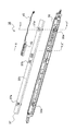
以下、図面を参照しながら本発明の実施形態について説明する。図1は、本発明の現像装置3a〜3dが搭載された画像形成装置100の概略断面図であり、ここではタンデム方式のカラー画像形成装置について示している。カラープリンター100本体内には4つの画像形成部Pa、Pb、Pc及びPdが、搬送方向上流側(図1では右側)から順に配設されている。これらの画像形成部Pa〜Pdは、異なる4色(シアン、マゼンタ、イエロー及びブラック)の画像に対応して設けられており、それぞれ帯電、露光、現像及び転写の各工程によりシアン、マゼンタ、イエロー及びブラックの画像を順次形成する。
Hereinafter, embodiments of the present invention will be described with reference to the drawings. FIG. 1 is a schematic cross-sectional view of an
これらの画像形成部Pa〜Pdには、各色の可視像(トナー像)を担持する感光体ドラム1a、1b、1c及び1dが配設されており、さらに駆動手段(図示せず)により図1において時計回りに回転する中間転写ベルト8が各画像形成部Pa〜Pdに隣接して設けられている。これらの感光体ドラム1a〜1d上に形成されたトナー像が、各感光体ドラム1a〜1dに当接しながら移動する中間転写ベルト8上に順次一次転写されて重畳される。その後、中間転写ベルト8上に一次転写されたトナー像は、二次転写ローラー9の作用によって記録媒体の一例としての転写紙P上に二次転写される。さらに、トナー像が二次転写された転写紙Pは、定着部13においてトナー像が定着された後、カラープリンター100本体より排出される。感光体ドラム1a〜1dを図1において反時計回りに回転させながら、各感光体ドラム1a〜1dに対する画像形成プロセスが実行される。
These image forming portions Pa to Pd are provided with photosensitive drums 1a, 1b, 1c and 1d which carry visible images (toner images) of the respective colors, and are further illustrated by a driving means (not shown). In FIG. 1, an
トナー像が二次転写される転写紙Pは、カラープリンター100の本体下部に配置された用紙カセット16内に収容されており、給紙ローラー12a及びレジストローラー対12bを介して二次転写ローラー9と後述する中間転写ベルト8の駆動ローラー11とのニップ部へと搬送される。中間転写ベルト8には誘電体樹脂製のシートが用いられ、継ぎ目を有しない(シームレス)ベルトが主に用いられる。また、二次転写ローラー9の下流側には中間転写ベルト8表面に残存するトナー等を除去するためのブレード状のベルトクリーナ19が配置されている。
The transfer paper P on which the toner image is secondarily transferred is accommodated in a
次に、画像形成部Pa〜Pdについて説明する。回転自在に配設された感光体ドラム1a〜1dの周囲及び下方には、感光体ドラム1a〜1dを帯電させる帯電器2a、2b、2c及び2dと、各感光体ドラム1a〜1dに画像情報を露光する露光装置5と、感光体ドラム1a〜1d上にトナー像を形成する現像装置3a、3b、3c及び3dと、感光体ドラム1a〜1d上に残留した現像剤(トナー)等を除去するクリーニング部7a、7b、7c及び7dが設けられている。
Next, the image forming units Pa to Pd will be described. There are
パソコン等の上位装置から画像データが入力されると、先ず、帯電器2a〜2dによって感光体ドラム1a〜1dの表面を一様に帯電させ、次いで露光装置5によって画像データに応じて光照射し、各感光体ドラム1a〜1d上に画像データに応じた静電潜像を形成する。現像装置3a〜3dには、それぞれシアン、マゼンタ、イエロー及びブラックの各色のトナーを含む二成分現像剤が所定量充填されている。なお、後述のトナー像の形成によって各現像装置3a〜3d内に充填された二成分現像剤中のトナーの割合が規定値を下回った場合にはトナーコンテナ(補給手段)4a〜4dから各現像装置3a〜3dにトナーが補給される。この現像剤中のトナーは、現像装置3a〜3dにより感光体ドラム1a〜1d上に供給され、静電的に付着することにより、露光装置5からの露光により形成された静電潜像に応じたトナー像が形成される。
When image data is input from a host device such as a personal computer, first, the surfaces of the photosensitive drums 1a to 1d are uniformly charged by the
そして、一次転写ローラー6a〜6dにより一次転写ローラー6a〜6dと感光体ドラム1a〜1dとの間に所定の転写電圧で電界が付与され、感光体ドラム1a〜1d上のシアン、マゼンタ、イエロー及びブラックのトナー像が中間転写ベルト8上に一次転写される。これらの4色の画像は、所定のフルカラー画像形成のために予め定められた所定の位置関係をもって形成される。その後、引き続き行われる新たな静電潜像の形成に備え、一次転写後に感光体ドラム1a〜1dの表面に残留したトナー等がクリーニング部7a〜7dにより除去される。
The primary transfer rollers 6a to 6d apply an electric field at a predetermined transfer voltage between the primary transfer rollers 6a to 6d and the photosensitive drums 1a to 1d, and cyan, magenta, yellow, and yellow on the photosensitive drums 1a to 1d. A black toner image is primarily transferred onto the
中間転写ベルト8は、上流側の従動ローラー10と、下流側の駆動ローラー11とに掛け渡されており、駆動モーター(図示せず)による駆動ローラー11の回転に伴い中間転写ベルト8が時計回りに回転を開始すると、転写紙Pがレジストローラー12bから所定のタイミングで駆動ローラー11とこれに隣接して設けられた二次転写ローラー9とのニップ部(二次転写ニップ部)へ搬送され、中間転写ベルト8上のフルカラー画像が転写紙P上に二次転写される。トナー像が二次転写された転写紙Pは定着部13へと搬送される。
The
定着部13に搬送された転写紙Pは、定着ローラー対13aにより加熱及び加圧されてトナー像が転写紙Pの表面に定着され、所定のフルカラー画像が形成される。フルカラー画像が形成された転写紙Pは、複数方向に分岐した分岐部14によって搬送方向が振り分けられる。転写紙Pの片面のみに画像を形成する場合は、そのまま排出ローラー15によって排出トレイ17に排出される。
The transfer paper P conveyed to the fixing
一方、転写紙Pの両面に画像を形成する場合は、定着部13を通過した転写紙Pは一旦排出ローラー15方向に搬送される。そして、転写紙Pの後端が分岐部14を通過した後に排出ローラー15を逆回転させるとともに分岐部14の搬送方向を切り換える。これにより、転写紙Pは後端から用紙搬送路18に振り分けられ、画像面を反転させた状態で二次転写ニップ部に再搬送される。そして、中間転写ベルト8上に形成された次のトナー像が、二次転写ローラー9によって転写紙Pの画像が形成されていない面に二次転写される。トナー像が二次転写された転写紙Pは、定着部13に搬送されてトナー像が定着された後、排出トレイ17に排出される。
On the other hand, when images are formed on both sides of the transfer paper P, the transfer paper P that has passed through the fixing
また、カラープリンター100本体の背面側には、排気ファン90が設けられており、排気ファン90は、カラープリンター100本体内の空気を装置本体外に排出する。
In addition, an
図2は、本発明の第1実施形態に係る現像装置3aの概略側面断面図である。なお、図2は図1の背面側から見た状態を示しており、現像装置3a内の各部材の配置は図1と左右が逆になっている。また、以下の説明では図1の画像形成部Paに配置される現像装置3aを例示するが、画像形成部Pb〜Pdに配置される現像装置3b〜3dの構成についても基本的に同様であるため説明を省略する。
FIG. 2 is a schematic sectional side view of the developing
図2に示すように、現像装置3aは、二成分現像剤(以下、単に現像剤と呼ぶ)が収納される現像容器(ケーシング)20を備えており、現像容器20は仕切壁20aによって攪拌搬送室21、供給搬送室22に区画されている。攪拌搬送室21及び供給搬送室22には、トナーコンテナ4a(図1参照)から供給されるトナー(正帯電トナー)をキャリアと混合して攪拌し、帯電させるための攪拌搬送スクリュー25a及び供給搬送スクリュー25bがそれぞれ回転可能に配設されている。
As shown in FIG. 2, the developing
そして、攪拌搬送スクリュー25a及び供給搬送スクリュー25bによって現像剤が攪拌されつつ軸方向(図2の紙面と垂直な方向)に搬送され、仕切壁20aの両端部に形成された不図示の現像剤通過路を介して攪拌搬送室21、供給搬送室22間を循環する。即ち、攪拌搬送室21、供給搬送室22、現像剤通過路によって現像容器20内に現像剤の循環経路が形成されている。
Then, the developer is agitated by the agitating / conveying
現像容器20は図2の右斜め上方に延在しており、現像容器20内において供給搬送スクリュー25bの上方にはトナー供給ローラー30が配置され、トナー供給ローラー30の右斜め上方には現像ローラー31が対向配置されている。そして、現像ローラー31は現像容器20の開口側(図2の右側)において感光体ドラム1a(図1参照)に対向している。トナー供給ローラー30及び現像ローラー31は、それぞれ回転軸周りに関して図中反時計回り方向に回転する。
The developing
攪拌搬送室21には、攪拌搬送スクリュー25aと対面して不図示のトナー濃度センサーが配置されており、トナー濃度センサーの検知結果に基づいてトナーコンテナ4aから不図示のトナー補給口を介して攪拌搬送室21にトナーが補給されるようになっている。トナー濃度センサーとしては、例えば、現像容器20内におけるトナーと磁性キャリアからなる二成分現像剤の透磁率を検出する透磁率センサーが用いられる。
In the agitating / conveying
トナー供給ローラー30は、図2において反時計方向に回転する非磁性の回転スリーブと、回転スリーブに内包される複数の磁極を有する固定マグネット体で構成される磁気ローラーである。
The
現像ローラー31は、図2において反時計回り方向に回転する円筒状の現像スリーブと、現像スリーブ内に固定された現像ローラー側磁極で構成されている。トナー供給ローラー30と現像ローラー31とはその対面位置(対向位置)において所定のギャップをもって対向している。現像ローラー側磁極は、固定マグネット体の対向する磁極(主極)と異極性である。
The developing
また、現像容器20には穂切りブレード(規制ブレード)33がトナー供給ローラー30の長手方向(図2の紙面と垂直な方向)に沿って取り付けられている。穂切りブレード33は、トナー供給ローラー30の回転方向(図中反時計回り)において、現像ローラー31とトナー供給ローラー30との対向位置よりも上流側に位置付けられている。そして、穂切りブレード33の先端部とトナー供給ローラー30表面との間には僅かな隙間(ギャップ)が形成されている。
Further, a spike cutting blade (regulating blade) 33 is attached to the developing
現像ローラー31には、直流電圧(以下、Vslv(DC)という)及び交流電圧(以下、Vslv(AC)という)が印加されている。トナー供給ローラー30には、直流電圧(以下、Vmag(DC)という)及び交流電圧(以下、Vmag(AC)という)が印加されている。これらの直流電圧及び交流電圧は、現像バイアス電源からバイアス制御回路(いずれも図示せず)を経由して現像ローラー31及びトナー供給ローラー30に印加される。
A DC voltage (hereinafter referred to as Vslv (DC)) and an AC voltage (hereinafter referred to as Vslv (AC)) are applied to the developing
前述のように、攪拌搬送スクリュー25a及び供給搬送スクリュー25bによって、現像剤が攪拌されつつ現像容器20内の攪拌搬送室21及び供給搬送室22を循環することにより現像剤中のトナーを帯電させる。供給搬送室22内の現像剤は、供給搬送スクリュー25bによってトナー供給ローラー30に搬送される。そして、トナー供給ローラー30上に磁気ブラシ(図示せず)を形成する。トナー供給ローラー30上の磁気ブラシは穂切りブレード33によって層厚規制された後、トナー供給ローラー30の回転によってトナー供給ローラー30と現像ローラー31との対向部分に搬送される。そして、トナー供給ローラー30に印加されるVmag(DC)と現像ローラー31に印加されるVslv(DC)との電位差ΔV、及び磁界によって現像ローラー31上にトナー薄層が形成される。
As described above, the toner in the developer is charged by circulating the stirring and conveying
現像ローラー31上のトナー層厚は現像剤の抵抗やトナー供給ローラー30と現像ローラー31との回転速度差等によっても変化するが、ΔVによって制御することができる。ΔVを大きくすると現像ローラー31上のトナー層は厚くなり、ΔVを小さくすると薄くなる。現像時におけるΔVの範囲は一般的に100V〜350V程度が適切である。
The thickness of the toner layer on the developing
トナー供給ローラー30上の磁気ブラシとの接触によって現像ローラー31上に形成されたトナー薄層は、現像ローラー31の回転によって感光体ドラム1aと現像ローラー31との対向部分(対向領域)に搬送される。現像ローラー31にはVslv(DC)及びVslv(AC)が印加されているため、感光体ドラム1aとの間の電位差によって現像ローラー31から感光体ドラム1aにトナーが飛翔し、感光体ドラム1a上の静電潜像が現像される。
The toner thin layer formed on the developing
現像に用いられずに残ったトナーは、再度現像ローラー31とトナー供給ローラー30との対向部分に搬送され、トナー供給ローラー30上の磁気ブラシによって回収される。そして、磁気ブラシは固定マグネット体の同極部分でトナー供給ローラー30から引き剥がされた後、供給搬送室22内に落下する。
Remaining toner that is not used for development is conveyed again to the opposite portion between the developing
その後、トナー濃度センサー(不図示)の検知結果に基づいてトナー補給口(不図示)から所定量のトナーが補給され、供給搬送室22及び攪拌搬送室21を循環する間に再び適正なトナー濃度で均一に帯電された二成分現像剤となる。この現像剤が再び供給攪拌スクリュー25bによりトナー供給ローラー30上に供給されて磁気ブラシを形成し、穂切りブレード33へ搬送される。
Thereafter, a predetermined amount of toner is replenished from a toner replenishing port (not shown) based on a detection result of a toner concentration sensor (not shown), and an appropriate toner concentration is again obtained while circulating through the
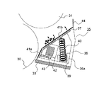
現像容器20における図2の右側壁において現像ローラー31の近傍には、現像容器20の内側に突出して、断面三角形状のトナー受け支持部材35が設けられている。図2に示すように、トナー受け支持部材35は現像容器20の長手方向(図2の紙面と垂直な方向)に沿って配置されており、トナー受け支持部材35の上面はトナー供給ローラー30及び現像ローラー31に対向するとともに、現像ローラー31からトナー供給ローラー30方向に向かって下方に傾斜する壁部を構成している。トナー受け支持部材35の上面には長手方向に沿って、現像ローラー31から引き剥がされて落下するトナーを受けるトナー受け部材37が取り付けられている。
In the vicinity of the developing
図3は、トナー受け支持部材35を現像容器20の内側(図2の左側)から見た斜視図、図4は、トナー受け支持部材35の分解斜視図、図5(a)、(b)は、トナー受け部材37の外観斜視図及び拡大斜視図、図6は、トナー受け支持部材35の内部構成を示す側面断面図である。なお、図4ではシート部材41a、41bの記載を省略している。また、図6ではトナー受け支持部材35の振動モーター43付近の断面(図4のXX′矢視断面)、及びトナー受け支持部材35のコイルバネ40付近の断面(図4のYY′矢視断面)の両方を重ねて図示している。
3 is a perspective view of the toner receiving
トナー受け部材37は板金製であり、2本のコイルバネ40を介して樹脂製の支持部材本体36に支持されている。具体的には、図5(a)、(b)に示すように、トナー受け部材37の両端部の2箇所にコイルバネ40の一端が係合する係合部37aが折り曲げ形成されており、コイルバネ40の他端にはバネ台座39が装着されている。バネ台座39は支持部材本体36のバネ台座保持部36aに保持される。また、トナー受け部材37の略中央部にはモーター取付ホルダー42を支持するホルダー保持部37bが折り曲げ形成されている。
The
トナー受け部材37の裏面にはモーター取付ホルダー42を介して振動モーター43が固定されている。モーター取付ホルダー42内には振動モーター43の駆動を制御するための回路や電子部品(図示せず)が実装されており、振動モーター43に電力を供給するためのリード線45が接続されている。
A
トナー受け部材37の表面にはシート部材41a、41bが貼り付けられている。シート部材41a、41bは、トナー受け部材37へのトナー付着を抑制するために、トナー受け部材37よりもトナーが付着し難い材質で形成されている。シート部材41a、41bの材質としては、例えばフッ素樹脂製シート等が挙げられる。シート部材41aは穂切りブレード33側の支持部材本体36とトナー受け部材37との境界を含むトナー受け部材37表面を覆うように貼り付けられている。また、シート部材41bはシール部材44側の支持部材本体36とトナー受け部材37との境界、係合部37a、及びホルダー保持部37bを含むトナー受け部材37表面を覆うように貼り付けられている。
また、支持部材本体36の上端にはフィルム状のシール部材44が設けられている。シール部材44は、先端部が感光体ドラム1aの表面に接触するように支持部材本体36の長手方向(図6の紙面と垂直な方向)に延在しており、現像容器20(図2参照)内のトナーが外部に漏出しないように遮蔽する機能を有している。
A film-
図7は、図4におけるモーター取付ホルダー42の分解斜視図である。モーター取付ホルダー42は、振動モーター43が固定されるモーター取付板42aとカバー部材42bとで構成され、振動モーター43の出力軸43aには加振用ウェイト50が固定されている。また、振動モーター43は出力軸43aがトナー受け部材37の長手方向に沿うように固定されている。
FIG. 7 is an exploded perspective view of the
図8は、振動モーター43の正面図であり、図9は、振動モーター43を加振ウェイト50側から見た側面図である。加振用ウェイト50は、振動モーター43の出力軸43a方向(図8の右方向)から見ると、図9に示すように円板の一部に切り欠き50aが形成されたカム形状をなしており、出力軸43aに対し非対称な形状となっている。出力軸43aが所定以上の速度で回転するとき、切り欠き部50aに作用する遠心力は他の部分に比べて小さいため、加振用ウェイト50には不均一な遠心力が加わる。この遠心力が出力軸43aに伝達されることにより、振動モーター43が振動する。なお、加振用ウェイト50の形状はカム形状に限定されず、出力軸43aに対し重心がずれるような任意の形状とすることができる。
FIG. 8 is a front view of the
図10は、現像装置3aの駆動中におけるトナー受け部材37の動作を示す概略側面図である。現像装置3aの駆動中に振動モーター43の出力軸43aを高速回転(例えば10,000rpm程度)させることにより、加振用ウェイト50も出力軸43aと共に高速回転する。このとき、加振用ウェイト50には不均一な遠心力が加わるため、出力軸43aを介して振動モーター43及びモーター取付ホルダー42が振動する。そして、モーター取付ホルダー42が固定されたトナー受け部材37も振動する。
FIG. 10 is a schematic side view showing the operation of the
トナー受け部材37の振動により、トナー受け部材37に堆積したトナーは離れ、振るい落とされる。
Due to the vibration of the
これにより、現像装置3a内のトナー供給ローラー30及び現像ローラー31が高速で回転し、トナー浮遊量が大きい場合であっても、トナー受け部材37上でのトナーの堆積を抑制できる。
Thereby, even when the
また、トナー受け部材37自体を振動させてトナーの堆積を防止するため、トナー受け部材37上のトナーを除去するブラシ部材等のトナー除去部材を別途設ける必要がなく、コンパクトで省スペースな構成となる。さらに、トナー除去部材に起因する異物が現像容器20内へ進入するおそれがないため、穂切りブレード33とトナー供給ローラー30との隙間に異物が挟まることによる白抜け画像等の画像不良を効果的に防止することができる。
Further, in order to prevent toner accumulation by vibrating the
さらに、トナー受け部材37の表面にはシート部材41a、41bが貼り付けられているため、トナー受け部材37へのトナーの付着を抑制することができる。また、シート部材41a、41bはトナー受け支持部材35とトナー受け部材37との境界、及び係合部37a、ホルダー保持部37bを覆うように貼り付けられているため、トナー受け支持部材35とトナー受け部材37との境界からのトナーの漏出、トナー受け支持部材35の内部へのトナーの進入や、トナーの進入に起因する振動モーター43の動作不良も防止することができる。
Further, since the
図11及び図12は、現像装置3aに用いられるトナー受け支持部材35の内部構成を示す側面断面図である。なお、図11はトナー受け支持部材35の振動モーター43付近の断面(図4のXX′矢視断面)を示し、図12はトナー受け支持部材35のコイルバネ40付近の断面(図4のYY′矢視断面)を示している。
11 and 12 are side cross-sectional views showing the internal configuration of the toner receiving
図11及び図12に示すように、トナー受け部材37はトナー供給ローラー30側の端縁37dのみが支持部材本体36に当接しており、反対側(感光体ドラム1a側)の端縁37eは自由端となっている。そして、トナー受け面38aの幅方向(図12の左右方向)の略中央部はコイルバネ40を介して支持部材本体36に支持されている。これにより、トナー受け部材37は端縁37dを支点として揺動可能に構成されている。また、振動モーター43は、出力軸43aがトナー受け部材37の長手方向と略平行になるように配置されている。
As shown in FIGS. 11 and 12, only the
さらに、トナー受け部材37は現像ローラー31に対向するトナー受け面38aがトナー供給ローラー30側から感光体ドラム1a側に向かって上り勾配となるように傾斜し、トナー供給ローラー30に対向するトナー落下面38bが略垂直になるように配置されている。
Further, the
非画像形成時に出力軸43aを高速回転(例えば10,000rpm程度)させることにより、加振用ウェイト50も出力軸43aと共に高速回転する。このとき、加振用ウェイト50には不均一な遠心力が加わるため、出力軸43aを介して振動モーター43及びモーター取付ホルダー42が振動する。そして、モーター取付ホルダー42が固定されたトナー受け部材37も振動する。具体的には、トナー受け部材37は端縁37dを支点として端縁37eに向かうにつれて振幅が大きくなるように振動する。
By rotating the
トナー受け部材37の振動により、図12に示すように、トナー受け部材37のトナー受け面38aに堆積したトナーはトナー受け面38aの傾斜に沿って下方(図12の白矢印方向)に滑り落ち、トナー落下面38bとトナー供給ローラー30とで挟まれた領域Rに落下する。
Due to the vibration of the
本実施形態では、図12に示すように、トナー受け部材37はトナー落下面38bが略垂直となるように配置されるため、領域Rのトナーが自由落下し易くなる。
In the present embodiment, as shown in FIG. 12, since the
ここで、領域Rに落下したトナーを供給搬送室22へ戻すために、非画像形成時にトナー供給ローラー30を画像形成時とは逆方向(図12の時計回り方向)に回転させる。トナー供給ローラー30を逆方向に回転させることにより、領域Rに落下して堆積したトナーはトナー供給ローラー30の表面に連れ回りしてトナー供給ローラー30と穂切りブレード33との隙間を通過し、供給搬送室22へ強制的に戻される。
Here, in order to return the toner that has fallen to the region R to the
また、本実施形態では、振動モーター43の出力軸43aを、出力軸43aのトナー受け部材37に対向する側の外周面が、トナー受け部材37の自由端(端縁37e)から支点(端縁37d)に向かって移動する方向(図11の反時計回り方向)に回転させている。出力軸43aをこの方向に回転させることで、トナー受け部材37はトナー受け面38aに堆積したトナーを端縁37e側から端縁37d側に移動させるように振動する。
In the present embodiment, the
一方、出力軸43aを逆方向(図11の時計回り方向)に回転させた場合は、トナー受け部材37の振動によってトナーを端縁37d側から端縁37e側にせり上がるように移動させてしまうため、トナー受け面38aに堆積したトナーが滑り落ちない。従って、上記実施形態のように振動モーター43の出力軸43aを回転させることで、トナー受け面38aに堆積したトナーを下り勾配に沿って領域Rへ効果的に落下させることができる。
On the other hand, when the
また、コイルバネ40はトナー受け面38aに対し略垂直に配置されているため、コイルバネ40の伸縮方向とトナー受け部材37の振動方向とが略一致し、コイルバネ40の伸縮による振動がトナー受け部材37に効率よく伝達される。従って、トナー受け部材37の振動を大きくすることができ、トナー受け面38aに堆積したトナーを振い落とす効果も高くなる。
In addition, since the
トナー受け部材37を振動させるタイミングやトナー供給ローラー30を逆方向に回転させるタイミングとしては、印字動作の終了毎に行っても良いし、印字枚数が所定枚数に到達した時点や現像装置3a内の温度が所定以上になった時点等、所定のタイミングで行うようにしても良い。また、トナー受け部材37を振動させるタイミングとトナー供給ローラー30を逆方向に回転させるタイミングは同じでも異なっていても良い。また、所定の印字枚数に到達する毎にトナー受け部材37を振動させることにより、印字枚数に応じてトナー受け部材の振動が自動的に実行される。従って、ユーザー自身がトナー受け部材37の振動を手動で設定する必要がなくなり、設定ミスや設定忘れ、或いは不必要な振動の実行を回避することができる。
The timing to vibrate the
ところで、単発印字時は連続印字時に比べてトナー受け部材37上にトナーが堆積し易い。これは、単発印字時はトナー供給ローラー30、現像ローラー31の回転が断続的に停止するため、連続印字時よりも現像容器20内の空気の流れが少ないためであると考えられる。同様に、高温高湿環境下ではトナーの流動性が低下するため、常温常湿環境下に比べてトナー受け部材37上にトナーが堆積し易い。
By the way, the toner is more easily deposited on the
そこで、単発印字時は連続印字時よりも少ない枚数毎に、高温高湿環境下では常温常湿環境下よりも少ない枚数毎に振動モーター43を作動させることで、トナー受け部材37上のトナーの堆積を効果的に抑制することができる。
Therefore, by operating the
図13は、本発明の第2実施形態に係る現像装置3aに用いられるトナー受け支持部材35の内部構成を示す側面断面図である。なお、図13はトナー受け支持部材35のコイルバネ40付近の断面(図4のYY′矢視断面)を示している。本実施形態では、コイルバネ40の一端は下方に延長され、先端に接点40aが形成されている。接点40aは導電板51に接触し、導電板51はバイアス電源53と電気的に接続されている。即ち、トナー受け部材37はコイルバネ40を介してバイアス電源53と電気的に接続されており、トナー供給ローラー30と同電位となっている。他の部分の構成は図11及び図12に示した第1実施形態と同様であるため説明を省略する。
FIG. 13 is a side sectional view showing the internal configuration of the toner receiving
本実施形態の構成によれば、トナー供給ローラー30とトナー受け部材37とを同電位とすることで、金属製のトナー受け部材37とトナー供給ローラー30との間の電流のリークを防止することができる。また、トナー供給ローラー30にはトナーと同極性(ここでは正極性)のバイアスが印加されるため、トナー受け部材37にもトナーと同極性のバイアスが印加されることになる。従って、トナーがトナー受け部材37に静電気的に付着せず、トナー受け部材37へのトナーの堆積を抑制することができる。更に、トナー供給ローラー30とトナー受け部材37とのリークを防止することも可能となる。
According to the configuration of the present embodiment, current leakage between the metal
その他本発明は、上記各実施形態に限定されず、本発明の趣旨を逸脱しない範囲で種々の変更が可能である。例えば、上記各実施形態に示したトナー受け支持部材35やトナー受け部材37の形状や構成は一例であって上記各実施形態に特に限定されるものではなく、これらは装置構成等に応じて適宜設定することができる。
In addition, the present invention is not limited to the above embodiments, and various modifications can be made without departing from the spirit of the present invention. For example, the shape and configuration of the toner receiving
また、上記実施形態では、本発明を、二成分現像剤を用い、トナー供給ローラー30上に磁気ブラシを形成し、トナー供給ローラー30から現像ローラー31にトナーのみを移動させ、現像ローラー31から感光体ドラム1a〜1dにトナーを供給する現像装置3a〜3dに適用したが、その他、図14に示すように、現像ローラー31とトナー供給ローラー30の配置を上記各実施形態とは逆にして、現像ローラー31(本構成においては上記各実施形態のトナー供給ローラー30と同様の構成の磁気ローラーとなる)表面に保持された二成分現像剤から成る磁気ブラシによって感光体ドラム1a〜1dにトナーを供給し、トナー供給ローラー30(本構成においては上記各実施形態の現像ローラー31と同様の構成となる)の表面に保持されているトナーを現像ローラー31に供給するとともに、トナー供給ローラー30を用いて現像ローラー31表面の余剰トナーを回収する現像装置にも適用することができる。この構成においても、現像ローラー31から落下したトナーがトナー供給ローラー30に対向する規制ブレード周辺へ堆積することを効果的に抑制できる。
In the above-described embodiment, the present invention uses a two-component developer, forms a magnetic brush on the
本発明は、ケーシングが、規制ブレードと対向領域との間において現像剤担持体と対向する壁部を有する現像装置に利用可能である。本発明の利用により、現像装置内の規制ブレード周辺におけるトナーの堆積を効果的に抑制することができる。また、上記現像装置を備えることにより、トナーの堆積に起因するトナー落ち等の画像不具合を効果的に防止できる画像形成装置となる。 INDUSTRIAL APPLICABILITY The present invention can be used for a developing device in which a casing has a wall portion facing a developer carrier between a regulating blade and a facing region. By utilizing the present invention, toner accumulation around the regulating blade in the developing device can be effectively suppressed. Further, by providing the developing device, an image forming apparatus that can effectively prevent image defects such as toner dropping due to toner accumulation.
Pa〜Pd 画像形成部
1a〜1d 感光体ドラム(像担持体)
3a〜3d 現像装置
4a〜4d トナーコンテナ
20 現像容器(ケーシング)
20a 仕切壁
30 トナー供給ローラー
31 現像ローラー
33 穂切りブレード(規制ブレード)
35 トナー受け支持部材
35a 空気流入孔
36 支持部材本体
37 トナー受け部材
39 バネ台座
40 コイルバネ(弾性部材)
41a、41b シート部材
42 モーター取付ホルダー
43 振動モーター(振動発生手段)
43a 出力軸
50 加振用ウェイト(振動発生手段)
100 カラープリンター(画像形成装置)
Pa to Pd Image forming section 1a to 1d Photosensitive drum (image carrier)
3a to
35 Toner receiving support member 35a
41a,
100 color printer (image forming device)
Claims (18)
前記現像ローラーと対向して配置され、前記現像ローラーとの対向領域において前記現像ローラーにトナーを供給するトナー供給ローラーと、
該トナー供給ローラーに所定の間隔を隔てて対向配置される規制ブレードと、
前記現像ローラー、前記トナー供給ローラー、及び前記規制ブレードを収容するケーシングと、
を有する現像装置において、
前記ケーシングは、前記規制ブレードと前記像担持体との間において前記現像ローラー又は前記トナー供給ローラーと対向するトナー受け支持部材を有しており、前記トナー受け支持部材の長手方向に沿って配置され前記現像ローラーから落下するトナーを受けるトナー受け部材と、該トナー受け部材を振動させる振動発生手段と、を設けたことを特徴とする現像装置。 A developing roller that is disposed to face an image carrier on which an electrostatic latent image is formed, and that supplies toner to the image carrier in a region facing the image carrier;
A toner supply roller that is disposed to face the developing roller and supplies toner to the developing roller in a region facing the developing roller;
A regulating blade disposed opposite to the toner supply roller at a predetermined interval;
A casing that houses the developing roller, the toner supply roller, and the regulating blade;
In a developing device having
The casing includes a toner receiving support member that faces the developing roller or the toner supply roller between the regulating blade and the image carrier, and is disposed along a longitudinal direction of the toner receiving support member. A developing device comprising: a toner receiving member that receives toner falling from the developing roller; and a vibration generating unit that vibrates the toner receiving member.
前記トナー受け部材は、前記トナー供給ローラー側の端縁を支点とし、前記像担持体側の端縁を自由端として揺動自在に支持されており、前記振動モーターの出力軸の前記トナー受け部材に対向する側の外周面が、前記トナー受け部材の自由端側から支点側に向かって移動する方向に前記出力軸を回転させることを特徴とする請求項3に記載の現像装置。 The vibration motor is fixed to a back surface of the toner receiving member so that an output shaft is substantially parallel to a longitudinal direction of the toner receiving member,
The toner receiving member is swingably supported with an edge on the toner supply roller side as a fulcrum, and an edge on the image carrier side as a free end. The toner receiving member is supported by the toner receiving member on the output shaft of the vibration motor. The developing device according to claim 3, wherein the output shaft is rotated in a direction in which an outer peripheral surface on the opposite side moves from a free end side of the toner receiving member toward a fulcrum side.
Priority Applications (1)
| Application Number | Priority Date | Filing Date | Title |
|---|---|---|---|
| JP2012007173A JP5538445B2 (en) | 2011-02-04 | 2012-01-17 | Developing device and image forming apparatus including the same |
Applications Claiming Priority (9)
| Application Number | Priority Date | Filing Date | Title |
|---|---|---|---|
| JP2011023168 | 2011-02-04 | ||
| JP2011023168 | 2011-02-04 | ||
| JP2011056185 | 2011-03-15 | ||
| JP2011056680 | 2011-03-15 | ||
| JP2011056184 | 2011-03-15 | ||
| JP2011056184 | 2011-03-15 | ||
| JP2011056680 | 2011-03-15 | ||
| JP2011056185 | 2011-03-15 | ||
| JP2012007173A JP5538445B2 (en) | 2011-02-04 | 2012-01-17 | Developing device and image forming apparatus including the same |
Publications (2)
| Publication Number | Publication Date |
|---|---|
| JP2012208469A true JP2012208469A (en) | 2012-10-25 |
| JP5538445B2 JP5538445B2 (en) | 2014-07-02 |
Family
ID=45606977
Family Applications (1)
| Application Number | Title | Priority Date | Filing Date |
|---|---|---|---|
| JP2012007173A Active JP5538445B2 (en) | 2011-02-04 | 2012-01-17 | Developing device and image forming apparatus including the same |
Country Status (5)
| Country | Link |
|---|---|
| US (1) | US8699925B2 (en) |
| EP (1) | EP2485093B1 (en) |
| JP (1) | JP5538445B2 (en) |
| KR (1) | KR101293000B1 (en) |
| CN (1) | CN102636975B (en) |
Cited By (21)
| Publication number | Priority date | Publication date | Assignee | Title |
|---|---|---|---|---|
| JP2014139629A (en) * | 2013-01-21 | 2014-07-31 | Kyocera Document Solutions Inc | Developing device and image forming apparatus including the same |
| JP2015125281A (en) * | 2013-12-26 | 2015-07-06 | 京セラドキュメントソリューションズ株式会社 | Developer collection apparatus and image forming apparatus |
| JP2017026902A (en) * | 2015-07-24 | 2017-02-02 | 京セラドキュメントソリューションズ株式会社 | Development device and image formation device equipped with the same |
| JP2017032931A (en) * | 2015-08-06 | 2017-02-09 | 京セラドキュメントソリューションズ株式会社 | Developing device and image forming apparatus including the same |
| JP2017058393A (en) * | 2015-09-14 | 2017-03-23 | 京セラドキュメントソリューションズ株式会社 | Developing device and image forming apparatus including the same |
| JP2017058392A (en) * | 2015-09-14 | 2017-03-23 | 京セラドキュメントソリューションズ株式会社 | Developing device and image forming apparatus including the same |
| JP2017058391A (en) * | 2015-09-14 | 2017-03-23 | 京セラドキュメントソリューションズ株式会社 | Developing device and image forming apparatus including the same |
| JP2017072628A (en) * | 2015-10-05 | 2017-04-13 | 京セラドキュメントソリューションズ株式会社 | Image forming apparatus |
| JP2017156500A (en) * | 2016-03-01 | 2017-09-07 | 京セラドキュメントソリューションズ株式会社 | Image forming apparatus |
| JP2018005027A (en) * | 2016-07-05 | 2018-01-11 | 京セラドキュメントソリューションズ株式会社 | Developing device and image forming apparatus including the same |
| JP2018045013A (en) * | 2016-09-13 | 2018-03-22 | 京セラドキュメントソリューションズ株式会社 | Developing device and image forming apparatus including the same |
| JP2018060074A (en) * | 2016-10-06 | 2018-04-12 | 京セラドキュメントソリューションズ株式会社 | Developing device and image forming apparatus including the same |
| JP2018084800A (en) * | 2016-11-11 | 2018-05-31 | 京セラドキュメントソリューションズ株式会社 | Image forming apparatus |
| US10001728B2 (en) | 2016-06-13 | 2018-06-19 | Kyocera Document Solutions Inc. | Developing device and image forming apparatus having a collection container with a swing portion |
| JP2018132628A (en) * | 2017-02-15 | 2018-08-23 | 京セラドキュメントソリューションズ株式会社 | Image forming apparatus |
| JP2018136397A (en) * | 2017-02-21 | 2018-08-30 | 京セラドキュメントソリューションズ株式会社 | Image forming apparatus |
| US10365581B1 (en) | 2018-01-24 | 2019-07-30 | Kyocera Document Solutions Inc. | Developing device and image forming apparatus including same |
| JP2019128441A (en) * | 2018-01-24 | 2019-08-01 | 京セラドキュメントソリューションズ株式会社 | Developing device and image forming apparatus including the same |
| JP2019128442A (en) * | 2018-01-24 | 2019-08-01 | 京セラドキュメントソリューションズ株式会社 | Developing device and image forming apparatus including the same |
| JP7330858B2 (en) | 2019-10-29 | 2023-08-22 | キヤノン株式会社 | image forming device |
| JP7412958B2 (en) | 2019-10-29 | 2024-01-15 | キヤノン株式会社 | Image forming device |
Families Citing this family (13)
| Publication number | Priority date | Publication date | Assignee | Title |
|---|---|---|---|---|
| JP5597611B2 (en) * | 2011-09-15 | 2014-10-01 | 京セラドキュメントソリューションズ株式会社 | Developing device and image forming apparatus having the same |
| JP5572654B2 (en) * | 2012-03-16 | 2014-08-13 | 京セラドキュメントソリューションズ株式会社 | Developing device and image forming apparatus |
| JP5684217B2 (en) * | 2012-11-19 | 2015-03-11 | 京セラドキュメントソリューションズ株式会社 | Developing device and image forming apparatus including the same |
| JP5721752B2 (en) * | 2013-01-21 | 2015-05-20 | 京セラドキュメントソリューションズ株式会社 | Developing device and image forming apparatus having the same |
| JP5968286B2 (en) * | 2013-09-27 | 2016-08-10 | 京セラドキュメントソリューションズ株式会社 | Toner container and image forming apparatus |
| US10295618B2 (en) * | 2014-09-19 | 2019-05-21 | Hitachi Metals, Ltd. | Magnetic permeability sensor and magnetic permeability detecting method, dielectric permittivity sensor and dielectric permittivity detecting method, and magnetic permeability and dielectric permittivity sensor and magnetic permeability and dielectric permittivity detecting method |
| US9454105B1 (en) * | 2015-07-17 | 2016-09-27 | Kabushiki Kaisha Toshiba | Image forming apparatus capable of removing an agglomerate of developing agent |
| CN107643661B (en) * | 2016-07-22 | 2020-06-16 | 柯尼卡美能达株式会社 | Developing device and image forming apparatus |
| JP2018072625A (en) * | 2016-10-31 | 2018-05-10 | 株式会社リコー | Developing device, process cartridge, and image forming apparatus |
| JP2018165767A (en) * | 2017-03-28 | 2018-10-25 | 京セラドキュメントソリューションズ株式会社 | Image forming apparatus |
| JP2022025486A (en) * | 2020-07-29 | 2022-02-10 | 京セラドキュメントソリューションズ株式会社 | Toner conveying device, and image forming apparatus including toner conveying device |
| JP2022120470A (en) | 2021-02-05 | 2022-08-18 | キヤノン株式会社 | Image formation apparatus |
| JP2023109502A (en) | 2022-01-27 | 2023-08-08 | キヤノン株式会社 | developing device |
Citations (8)
| Publication number | Priority date | Publication date | Assignee | Title |
|---|---|---|---|---|
| JPS6133053U (en) * | 1984-07-28 | 1986-02-28 | コニカ株式会社 | developing device |
| JPS6360162U (en) * | 1986-10-09 | 1988-04-21 | ||
| JPH0588537A (en) * | 1991-09-27 | 1993-04-09 | Minolta Camera Co Ltd | Developing device |
| JP2006058355A (en) * | 2004-08-17 | 2006-03-02 | Fuji Xerox Co Ltd | Developing device and image forming apparatus using same |
| JP2007010988A (en) * | 2005-06-30 | 2007-01-18 | Kyocera Mita Corp | Developing device |
| JP2009180994A (en) * | 2008-01-31 | 2009-08-13 | Brother Ind Ltd | Image forming apparatus |
| JP2010072013A (en) * | 2008-09-16 | 2010-04-02 | Ricoh Co Ltd | Toner supply device |
| JP2010276954A (en) * | 2009-05-29 | 2010-12-09 | Kyocera Mita Corp | Image forming apparatus |
Family Cites Families (9)
| Publication number | Priority date | Publication date | Assignee | Title |
|---|---|---|---|---|
| JPS5256939A (en) * | 1975-11-06 | 1977-05-10 | Fuji Xerox Co Ltd | Developing apparatus for electronic copying machine |
| JPS5263342A (en) * | 1975-11-20 | 1977-05-25 | Fuji Xerox Co Ltd | Developing apparatus for electrophotographic copying machine |
| JPS6133053A (en) | 1984-07-25 | 1986-02-15 | Mitsubishi Electric Corp | Exchange device |
| JP3372691B2 (en) * | 1995-01-21 | 2003-02-04 | 株式会社リコー | Image forming device |
| US6512909B2 (en) * | 2000-08-03 | 2003-01-28 | Kyocera Corporation | Image forming process and apparatus and control method thereof |
| JP2005099239A (en) | 2003-09-24 | 2005-04-14 | Konica Minolta Business Technologies Inc | Image forming apparatus |
| JP2009047868A (en) * | 2007-08-18 | 2009-03-05 | Konica Minolta Business Technologies Inc | Developing apparatus and image forming device |
| JP2009093032A (en) | 2007-10-11 | 2009-04-30 | Canon Inc | Developing device and image forming apparatus |
| JP2009122509A (en) | 2007-11-16 | 2009-06-04 | Ricoh Co Ltd | Developing device and image forming apparatus |
-
2012
- 2012-01-17 JP JP2012007173A patent/JP5538445B2/en active Active
- 2012-01-17 KR KR1020120005227A patent/KR101293000B1/en active IP Right Grant
- 2012-01-19 US US13/353,617 patent/US8699925B2/en active Active
- 2012-02-03 EP EP12153897.9A patent/EP2485093B1/en active Active
- 2012-02-03 CN CN201210028256.4A patent/CN102636975B/en active Active
Patent Citations (8)
| Publication number | Priority date | Publication date | Assignee | Title |
|---|---|---|---|---|
| JPS6133053U (en) * | 1984-07-28 | 1986-02-28 | コニカ株式会社 | developing device |
| JPS6360162U (en) * | 1986-10-09 | 1988-04-21 | ||
| JPH0588537A (en) * | 1991-09-27 | 1993-04-09 | Minolta Camera Co Ltd | Developing device |
| JP2006058355A (en) * | 2004-08-17 | 2006-03-02 | Fuji Xerox Co Ltd | Developing device and image forming apparatus using same |
| JP2007010988A (en) * | 2005-06-30 | 2007-01-18 | Kyocera Mita Corp | Developing device |
| JP2009180994A (en) * | 2008-01-31 | 2009-08-13 | Brother Ind Ltd | Image forming apparatus |
| JP2010072013A (en) * | 2008-09-16 | 2010-04-02 | Ricoh Co Ltd | Toner supply device |
| JP2010276954A (en) * | 2009-05-29 | 2010-12-09 | Kyocera Mita Corp | Image forming apparatus |
Cited By (30)
| Publication number | Priority date | Publication date | Assignee | Title |
|---|---|---|---|---|
| US9158229B2 (en) | 2013-01-21 | 2015-10-13 | Kyocera Document Solutions Inc. | Development device and image forming apparatus including the same |
| JP2014139629A (en) * | 2013-01-21 | 2014-07-31 | Kyocera Document Solutions Inc | Developing device and image forming apparatus including the same |
| JP2015125281A (en) * | 2013-12-26 | 2015-07-06 | 京セラドキュメントソリューションズ株式会社 | Developer collection apparatus and image forming apparatus |
| JP2017026902A (en) * | 2015-07-24 | 2017-02-02 | 京セラドキュメントソリューションズ株式会社 | Development device and image formation device equipped with the same |
| US9658570B2 (en) | 2015-07-24 | 2017-05-23 | Kyocera Document Solutions Inc. | Developing device including a toner receiving member vibrated by a vibration generation device, and image forming apparatus including the same |
| JP2017032931A (en) * | 2015-08-06 | 2017-02-09 | 京セラドキュメントソリューションズ株式会社 | Developing device and image forming apparatus including the same |
| US9665037B2 (en) | 2015-09-14 | 2017-05-30 | Kyocera Document Solutions Inc. | Developing device and image forming apparatus including same |
| JP2017058393A (en) * | 2015-09-14 | 2017-03-23 | 京セラドキュメントソリューションズ株式会社 | Developing device and image forming apparatus including the same |
| JP2017058392A (en) * | 2015-09-14 | 2017-03-23 | 京セラドキュメントソリューションズ株式会社 | Developing device and image forming apparatus including the same |
| JP2017058391A (en) * | 2015-09-14 | 2017-03-23 | 京セラドキュメントソリューションズ株式会社 | Developing device and image forming apparatus including the same |
| US9639024B2 (en) | 2015-09-14 | 2017-05-02 | Kyocera Document Solutions Inc. | Developing device and image forming apparatus including same |
| JP2017072628A (en) * | 2015-10-05 | 2017-04-13 | 京セラドキュメントソリューションズ株式会社 | Image forming apparatus |
| JP2017156500A (en) * | 2016-03-01 | 2017-09-07 | 京セラドキュメントソリューションズ株式会社 | Image forming apparatus |
| US10001728B2 (en) | 2016-06-13 | 2018-06-19 | Kyocera Document Solutions Inc. | Developing device and image forming apparatus having a collection container with a swing portion |
| JP2018005027A (en) * | 2016-07-05 | 2018-01-11 | 京セラドキュメントソリューションズ株式会社 | Developing device and image forming apparatus including the same |
| US10042283B2 (en) | 2016-07-05 | 2018-08-07 | Kyocera Document Solutions Inc. | Developing device that removes toner accumulated on top surface of regulating blade with simple configuration, and image forming apparatus including the same |
| JP2018045013A (en) * | 2016-09-13 | 2018-03-22 | 京セラドキュメントソリューションズ株式会社 | Developing device and image forming apparatus including the same |
| US10261438B2 (en) | 2016-09-13 | 2019-04-16 | Kyocera Document Solutions Inc. | Toner-receiving and toner-supply/developing roller systems for controlling toner accumulation and drop during toner recovery |
| JP2018060074A (en) * | 2016-10-06 | 2018-04-12 | 京セラドキュメントソリューションズ株式会社 | Developing device and image forming apparatus including the same |
| US10156814B2 (en) | 2016-10-06 | 2018-12-18 | Kyocera Document Solutions Inc. | Developing device including a film member which is disposed on inner wall portion of casing and image forming apparatus |
| JP2018084800A (en) * | 2016-11-11 | 2018-05-31 | 京セラドキュメントソリューションズ株式会社 | Image forming apparatus |
| JP2018132628A (en) * | 2017-02-15 | 2018-08-23 | 京セラドキュメントソリューションズ株式会社 | Image forming apparatus |
| JP2018136397A (en) * | 2017-02-21 | 2018-08-30 | 京セラドキュメントソリューションズ株式会社 | Image forming apparatus |
| US10365581B1 (en) | 2018-01-24 | 2019-07-30 | Kyocera Document Solutions Inc. | Developing device and image forming apparatus including same |
| JP2019128441A (en) * | 2018-01-24 | 2019-08-01 | 京セラドキュメントソリューションズ株式会社 | Developing device and image forming apparatus including the same |
| JP2019128442A (en) * | 2018-01-24 | 2019-08-01 | 京セラドキュメントソリューションズ株式会社 | Developing device and image forming apparatus including the same |
| JP7073738B2 (en) | 2018-01-24 | 2022-05-24 | 京セラドキュメントソリューションズ株式会社 | A developing device and an image forming device equipped with it |
| JP7081172B2 (en) | 2018-01-24 | 2022-06-07 | 京セラドキュメントソリューションズ株式会社 | A developing device and an image forming device equipped with it |
| JP7330858B2 (en) | 2019-10-29 | 2023-08-22 | キヤノン株式会社 | image forming device |
| JP7412958B2 (en) | 2019-10-29 | 2024-01-15 | キヤノン株式会社 | Image forming device |
Also Published As
| Publication number | Publication date |
|---|---|
| US20120201575A1 (en) | 2012-08-09 |
| EP2485093B1 (en) | 2019-03-27 |
| KR101293000B1 (en) | 2013-08-02 |
| US8699925B2 (en) | 2014-04-15 |
| EP2485093A1 (en) | 2012-08-08 |
| KR20120090799A (en) | 2012-08-17 |
| CN102636975A (en) | 2012-08-15 |
| JP5538445B2 (en) | 2014-07-02 |
| CN102636975B (en) | 2014-06-25 |
Similar Documents
| Publication | Publication Date | Title |
|---|---|---|
| JP5538445B2 (en) | Developing device and image forming apparatus including the same | |
| JP5783959B2 (en) | Developing device and image forming apparatus including the same | |
| JP5642116B2 (en) | Developing device and image forming apparatus including the same | |
| JP6319221B2 (en) | Developing device and image forming apparatus including the same | |
| JP6304184B2 (en) | Developing device and image forming apparatus including the same | |
| JP6304160B2 (en) | Developing device and image forming apparatus including the same | |
| JP6314945B2 (en) | Developing device and image forming apparatus including the same | |
| JP6319242B2 (en) | Developing device and image forming apparatus including the same | |
| JP6327228B2 (en) | Image forming apparatus | |
| JP6477542B2 (en) | Image forming apparatus | |
| JP6327227B2 (en) | Developing device and image forming apparatus including the same | |
| JP2019078828A (en) | Developing device and image forming apparatus including the same | |
| JP2017156499A (en) | Developing device and image forming apparatus including the same | |
| JP2019128441A (en) | Developing device and image forming apparatus including the same | |
| JP6565844B2 (en) | Developing device and image forming apparatus including the same | |
| JP6327229B2 (en) | Image forming apparatus | |
| JP2018045012A (en) | Developing device and image forming apparatus including the same | |
| JP6635068B2 (en) | Developing device and image forming apparatus provided with the same | |
| JP2017219667A (en) | Development device and image formation apparatus having the same | |
| JP2017032930A (en) | Developing device and image forming apparatus including the same | |
| JP2017058390A (en) | Developing device and image forming apparatus including the same | |
| JP2017223817A (en) | Development apparatus and image forming apparatus including the same | |
| JP2019124721A (en) | Developing device and image forming device equipped therewith | |
| JP2019078829A (en) | Developing device and image forming apparatus including the same | |
| JP2018031841A (en) | Developing device and image forming apparatus including the same |
Legal Events
| Date | Code | Title | Description |
|---|---|---|---|
| A621 | Written request for application examination |
Free format text: JAPANESE INTERMEDIATE CODE: A621 Effective date: 20130321 |
|
| A977 | Report on retrieval |
Free format text: JAPANESE INTERMEDIATE CODE: A971007 Effective date: 20131211 |
|
| A131 | Notification of reasons for refusal |
Free format text: JAPANESE INTERMEDIATE CODE: A131 Effective date: 20131224 |
|
| A521 | Request for written amendment filed |
Free format text: JAPANESE INTERMEDIATE CODE: A523 Effective date: 20140115 |
|
| TRDD | Decision of grant or rejection written | ||
| A01 | Written decision to grant a patent or to grant a registration (utility model) |
Free format text: JAPANESE INTERMEDIATE CODE: A01 Effective date: 20140401 |
|
| R150 | Certificate of patent or registration of utility model |
Ref document number: 5538445 Country of ref document: JP Free format text: JAPANESE INTERMEDIATE CODE: R150 |
|
| A61 | First payment of annual fees (during grant procedure) |
Free format text: JAPANESE INTERMEDIATE CODE: A61 Effective date: 20140428 |
|
| RD03 | Notification of appointment of power of attorney |
Free format text: JAPANESE INTERMEDIATE CODE: R3D03 |
|
| R250 | Receipt of annual fees |
Free format text: JAPANESE INTERMEDIATE CODE: R250 |