JP2012207228A - Phosphor and light-emitting device using the same - Google Patents
Phosphor and light-emitting device using the same Download PDFInfo
- Publication number
- JP2012207228A JP2012207228A JP2012153648A JP2012153648A JP2012207228A JP 2012207228 A JP2012207228 A JP 2012207228A JP 2012153648 A JP2012153648 A JP 2012153648A JP 2012153648 A JP2012153648 A JP 2012153648A JP 2012207228 A JP2012207228 A JP 2012207228A
- Authority
- JP
- Japan
- Prior art keywords
- phosphor
- light
- emitting device
- metal
- activated
- Prior art date
- Legal status (The legal status is an assumption and is not a legal conclusion. Google has not performed a legal analysis and makes no representation as to the accuracy of the status listed.)
- Pending
Links
Images


Abstract
Description
本発明は、窒化物又は酸窒化物を母体とする高輝度の蛍光体に関する。本発明はまた、この蛍光体を用いた蛍光体含有組成物及び発光装置、並びにその発光装置を用いた画像表示装置及び照明装置に関する。 The present invention relates to a high-luminance phosphor based on nitride or oxynitride. The present invention also relates to a phosphor-containing composition and a light emitting device using the phosphor, and an image display device and an illumination device using the light emitting device.
蛍光体は、蛍光灯、蛍光表示管(VFD)、フィールドエミッションディスプレイ(FED)、プラズマディスプレイパネル(PDP)、陰極線管(CRT)、白色発光ダイオード(LED)などに用いられている。これらのいずれの用途においても、蛍光体を発光させるためには、蛍光体を励起するためのエネルギーを蛍光体に供給する必要があり、蛍光体は真空紫外線、紫外線、可視光線、電子線などの高いエネルギーを有する励起源により励起されて、紫外線、可視光線、赤外線を発する。しかしながら、蛍光体は前記のような励起源に長時間曝されると、蛍光体の輝度が低下するという問題があった。 Phosphors are used in fluorescent lamps, fluorescent display tubes (VFD), field emission displays (FED), plasma display panels (PDP), cathode ray tubes (CRT), white light emitting diodes (LEDs) and the like. In any of these applications, in order to make the phosphor emit light, it is necessary to supply the phosphor with energy for exciting the phosphor, and the phosphor is not limited to vacuum ultraviolet rays, ultraviolet rays, visible rays, electron beams, etc. When excited by an excitation source having high energy, it emits ultraviolet rays, visible rays, and infrared rays. However, when the phosphor is exposed to the excitation source as described above for a long time, there is a problem that the luminance of the phosphor decreases.
そこで、近年、従来のケイ酸塩蛍光体、リン酸塩蛍光体、アルミン酸塩蛍光体、ホウ酸塩蛍光体、硫化物蛍光体、酸硫化物蛍光体などの蛍光体に代わり、三元系以上の窒化物について多くの新規物質が合成されている。特に最近、窒化珪素をベースとした多成分窒化物や酸窒化物において優れた特性を有する蛍光体が開発されている。 Therefore, in recent years, ternary systems have been used in place of conventional phosphors such as silicate phosphors, phosphate phosphors, aluminate phosphors, borate phosphors, sulfide phosphors, and oxysulfide phosphors. Many new materials have been synthesized for the above nitrides. Particularly recently, phosphors having excellent characteristics in multi-component nitrides and oxynitrides based on silicon nitride have been developed.
特許文献1には、一般式MxSiyNz:Eu[ここでMはCa,Sr,Baからなる群から選択される少なくとも一つのアルカリ土類金属元素であり、かつz=2/3x+4/3yである]で表される蛍光体が開示されている。これらの蛍光体は、アルカリ土類金属メタルを窒化してアルカリ土類金属の窒化物を合成し、これに窒化珪素を加えて合成するか、又はアルカリ土類金属及び珪素のイミドを原料としてN2又はAr気流中で加熱することによって合成されている。いずれも空気や水分に敏感なアルカリ土類金属メタルを原料として使用しなくてはならず、工業的な大量合成には問題があった。 In Patent Document 1, the general formula M x Si y N z : Eu [where M is at least one alkaline earth metal element selected from the group consisting of Ca, Sr, and Ba, and z = 2 / 3x + 4. / 3y] is disclosed. These phosphors are synthesized by nitriding an alkaline earth metal metal to synthesize an alkaline earth metal nitride and adding silicon nitride thereto, or using an alkaline earth metal and silicon imide as a raw material. It is synthesized by heating in 2 or Ar airflow. In both cases, alkaline earth metal metals sensitive to air and moisture had to be used as raw materials, and there was a problem in industrial mass synthesis.
また、特許文献2には、構造M16Si15O6N32のオキシニトリド、構造MSiAl2O3N2、M13Si18Al12O18N36、MSi5Al2ON9及びM3Si5AlON10のサイアロンから由来する酸窒化物蛍光体が開示されている。特に、MがSrの場合に、SrCO3とAlN、Si3N4とを1:2:1の割合で混合し、還元雰囲気中(N2/H2)で加熱し、SrSiAl2O3N2:Eu2+が得られたことが記載されている。
この場合、得られる蛍光体は、酸窒化物のみであり、酸素を含まない窒化物は得られていない。
In addition,
In this case, the obtained phosphor is only oxynitride, and no nitride containing no oxygen is obtained.
また、上記窒化物又は酸窒化物蛍光体は、使用される原料粉末の反応性がいずれも低いことから、焼成時に原料混合粉末の間の固相反応を促進する目的で高温において圧縮成形した状態、すなわち原料粉末間の接触面積を多くして加熱されるために、非常に硬い焼結体の状態で合成される。よって、この様にして得られた焼結体は蛍光体の使用目的に適した微粉末状態まで粉砕する必要がある。ところが、硬い焼結体からなる蛍光体を通常の機械的粉砕方法、例えばジョークラッシャーやボールミルなどを使用して長時間と多大なエネルギーをかけて粉砕すると、蛍光体の結晶母体中に多数の欠陥を発生させてしまい、蛍光体の発光強度を著しく低下させてしまうという不都合が生じていた。 In addition, since the nitride or oxynitride phosphor has a low reactivity of the raw material powder used, it is compression molded at a high temperature for the purpose of promoting a solid phase reaction between the raw material mixed powders during firing. That is, in order to be heated by increasing the contact area between the raw material powders, it is synthesized in the state of a very hard sintered body. Therefore, the sintered body obtained in this way needs to be pulverized to a fine powder suitable for the intended use of the phosphor. However, when a phosphor made of a hard sintered body is pulverized over a long period of time and with a large amount of energy using a normal mechanical pulverization method such as a jaw crusher or a ball mill, many defects are present in the crystal matrix of the phosphor. Has been caused, and the emission intensity of the phosphor is significantly reduced.
このために、加熱時に圧縮成形せずに粉末状態で焼成する方法が試みられたが、低温では原料の窒化物粉末間での固相反応が促進せずに目的の蛍光体が生成しないため、1800℃以上の高温で蛍光体を合成する必要があった。ところが、この様な高温での焼成時には窒化物原料からの窒素の脱離を伴う分解反応が起こるという不都合が発生するために、それを抑制する目的で5気圧以上の窒素ガス雰囲気下で焼成する必要があり、高い焼成エネルギーが必要とされるだけでなく、非常に高価な高温高圧焼成炉が必要となり、蛍光体の製造コストを上昇させる原因となっていた。 For this reason, a method of firing in a powder state without compression molding at the time of heating was attempted, but since the target phosphor is not generated at low temperature without promoting a solid phase reaction between the nitride powders of the raw material, It was necessary to synthesize the phosphor at a high temperature of 1800 ° C. or higher. However, when firing at such a high temperature, there arises a disadvantage that a decomposition reaction accompanied by desorption of nitrogen from the nitride raw material occurs, and thus firing is performed in a nitrogen gas atmosphere of 5 atm or more for the purpose of suppressing it. Therefore, not only high firing energy is required, but also a very expensive high-temperature and high-pressure firing furnace is required, which increases the manufacturing cost of the phosphor.
また、酸素濃度の低い窒化物を合成する際には、アルカリ土類金属酸化物の原料粉末を使用する代わりに窒化カルシウム(Ca3N2)、窒化ストロンチウム(Sr3N2)などアルカリ土類金属窒化物を使用することが必要であるが、一般に2価の金属窒化物は水分含有雰囲気下で不安定であり、水分と反応して水酸化物を生成しやすく、特にSrの場合はこの傾向が著しい。このため、合成される蛍光体に含有される酸素濃度を低く抑えることが難しかった。 When a nitride having a low oxygen concentration is synthesized, an alkaline earth such as calcium nitride (Ca 3 N 2 ) or strontium nitride (Sr 3 N 2 ) is used instead of using an alkaline earth metal oxide raw material powder. Although it is necessary to use a metal nitride, in general, a divalent metal nitride is unstable in a moisture-containing atmosphere, and easily reacts with moisture to form a hydroxide, particularly in the case of Sr. The trend is remarkable. For this reason, it was difficult to keep the oxygen concentration contained in the synthesized phosphor low.
このようなことから、これらの金属窒化物を原料として使用しない新たな製造方法が求められていた。 For these reasons, a new manufacturing method that does not use these metal nitrides as raw materials has been demanded.
近年、金属を出発原料とした窒化物蛍光体の製造方法に関し、特許文献3が報告された。特許文献3には窒化アルミニウム系蛍光体の製造方法の一例が開示され、原料として、遷移元素、希土類元素、アルミニウム及びその合金が使用できる旨が記載されている。しかし、実際に合金を原料として用いた実施例は記載されておらず、Al源としてAl金属を用いることを特徴としている。また、原料に着火し、瞬時に高温(3000K)まで上昇させる燃焼合成法を用いる点で、本発明と大きく異なり、この方法で高特性の蛍光体を得ることは困難であると推測される。すなわち、瞬時に3000Kという高温まで昇温させる方法では付活元素を均一に分布させることは出来ず、特性の高い蛍光体を得ることは困難である。また、合金原料から得られるアルカリ土類元素を含む窒化物蛍光体、更に珪素を含む窒化物蛍光体に関する記載は無い。 In recent years, Patent Document 3 has been reported regarding a method for producing a nitride phosphor using a metal as a starting material. Patent Document 3 discloses an example of a method for producing an aluminum nitride phosphor, which describes that transition elements, rare earth elements, aluminum and alloys thereof can be used as raw materials. However, an example using an alloy as a raw material is not described, and it is characterized by using Al metal as an Al source. In addition, it differs from the present invention in that a combustion synthesis method is used to ignite the raw material and instantaneously raise the temperature to a high temperature (3000 K). That is, with the method of instantaneously raising the temperature to 3000 K, the activating elements cannot be uniformly distributed, and it is difficult to obtain a phosphor with high characteristics. Moreover, there is no description regarding a nitride phosphor containing an alkaline earth element obtained from an alloy raw material, and further a nitride phosphor containing silicon.
合金を原料として窒化物あるいは酸窒化物を母体とする蛍光体を製造する新規な方法において、さらに高輝度な蛍光体の提供を可能とする技術が求められている。
本発明は、簡便な手法により、蛍光体の輝度を向上させる技術を提供することを目的とする。
In a new method for producing a phosphor using an alloy as a raw material and a nitride or oxynitride as a base material, a technique capable of providing a phosphor with higher brightness is required.
An object of this invention is to provide the technique which improves the brightness | luminance of fluorescent substance by a simple method.
本発明者等は、合金を原料として製造された窒化物又は酸窒化物を母体とする蛍光体において、この蛍光体を必要に応じて粉砕、分級し、当該蛍光体の10倍の重量の水に分散させた後、1時間静置して得られる上澄み液中の溶解イオンの量の指標である電気伝導度と、蛍光体の発光効率とに相関関係があることを見出し、本発明を完成させた。
即ち、本発明は以下の(1)〜(7)を要旨とするものである。
The inventors of the present invention have prepared phosphors based on nitrides or oxynitrides manufactured using alloys as raw materials, and pulverizing and classifying the phosphors as necessary, and water having a
That is, the gist of the present invention is the following (1) to (7).
(1) 下記一般式[2]で表される窒化物蛍光体であって、Cu−Kα線(1.54184Å)を用いた粉末X線回折パターンにおいて、2θが35.5゜〜37゜の範囲における最強ピークの高さImaxに対する、2θ=33.2゜±0.2゜のピークの高さIpの強度比をI=(Ip×100)/Imaxとするとき、Iが3以下であることを特徴とする窒化物蛍光体。
M1’ a’Srb’Cac’Ale’Sif’Ng’ [2]
(但し、a’、b’、c’、e’、f’、g’はそれぞれ下記の範囲の値である。
0.00001≦a’≦0.15
0.6≦b’≦0.99999
0≦c’<1
a’+b’+c’=1
0.8≦e’≦1.2
0.8≦f’≦1.2
2.5≦g’≦3.5
M1’はEu及び/又はCeを表す。)
(1) A nitride phosphor represented by the following general formula [2], wherein 2θ is 35.5 ° to 37 ° in a powder X-ray diffraction pattern using Cu-Kα rays (1.54184 mm). When the intensity ratio of the peak height I p of 2θ = 33.2 ° ± 0.2 ° to the height I max of the strongest peak in the range is I = (I p × 100) / I max A nitride phosphor characterized by being 3 or less.
M 1 ′ a ′ Sr b ′ Ca c ′ Al e ′ Sif ′ N g ′ [2]
(However, a ′, b ′, c ′, e ′, f ′, and g ′ are values in the following ranges, respectively.
0.00001 ≦ a ′ ≦ 0.15
0.6 ≦ b ′ ≦ 0.99999
0 ≦ c ′ <1
a ′ + b ′ + c ′ = 1
0.8 ≦ e ′ ≦ 1.2
0.8 ≦ f ′ ≦ 1.2
2.5 ≦ g ′ ≦ 3.5
M 1 ′ represents Eu and / or Ce. )
(2) M1’がEuである(1)に記載の窒化物蛍光体。 (2) The nitride phosphor according to (1), wherein M 1 ′ is Eu.
(3) 0.7≦b’≦0.99999である(1)又は(2)記載の窒化物蛍光体。 (3) The nitride phosphor according to (1) or (2), wherein 0.7 ≦ b ′ ≦ 0.99999.
(4) 酸素を5重量%以下含有する(1)ないし(3)のいずれかに記載の窒化物蛍光体。 (4) The nitride phosphor according to any one of (1) to (3), which contains 5% by weight or less of oxygen.
(5) (1)ないし(4)のいずれかに記載の蛍光体と液状媒体とを含有することを特徴とする蛍光体含有組成物。 (5) A phosphor-containing composition comprising the phosphor according to any one of (1) to (4) and a liquid medium.
(6) 励起光源と、該励起光源からの光の少なくとも一部を波長変換する蛍光体とを有する発光装置において、該蛍光体が(1)〜(4)のいずれかの蛍光体であることを特徴とする発光装置。 (6) In a light emitting device having an excitation light source and a phosphor that converts the wavelength of at least part of light from the excitation light source, the phosphor is any one of (1) to (4). A light emitting device characterized by the above.
(7) (6)に記載の発光装置を有することを特徴とする画像表示装置。 (7) An image display device comprising the light emitting device according to (6).
(8) (6)に記載の発光装置を有することを特徴とする照明装置。 (8) A lighting device comprising the light emitting device according to (6).
本発明によると、簡便な手法により、蛍光体の輝度を向上させることができる。
また、この蛍光体を含有する組成物を用いることによって、発光効率の高い発光装置を得ることができる。この発光装置は、画像表示装置や照明装置等の用途に好適に用いられる。
According to the present invention, the brightness of the phosphor can be improved by a simple method.
In addition, by using a composition containing this phosphor, a light emitting device with high luminous efficiency can be obtained. This light emitting device is suitably used for applications such as an image display device and a lighting device.
以下、本発明の実施の形態について詳細に説明するが、本発明は以下の実施の形態に限定されるものではなく、その要旨の範囲内で種々変形して実施することができる。
なお、本明細書において「〜」を用いて表される数値範囲は、「〜」の前後に記載される数値を下限値及び上限値として含む範囲を意味する。
Hereinafter, embodiments of the present invention will be described in detail. However, the present invention is not limited to the following embodiments, and various modifications can be made within the scope of the gist of the present invention.
In the present specification, a numerical range represented by using “to” means a range including numerical values described before and after “to” as a lower limit value and an upper limit value.
[蛍光体の組成]
本発明の窒化物又は酸窒化物を母体とする蛍光体の組成については特に制限はないが、以下に例を挙げて説明する。
[Composition of phosphor]
Although there is no restriction | limiting in particular about the composition of the fluorescent substance which makes the nitride or oxynitride of this invention a base material, An example is given and demonstrated below.
本発明の蛍光体は、好ましくは付活元素M1と、少なくともSiを含む4価の金属元素M4と、Si以外の金属元素の1種類以上とを含むものであって、詳しくは、本発明の蛍光体は、付活元素M1、2価の金属元素M2、及び少なくともSiを含む4価の金属元素M4を含むものである。例えば、Sr2Si5N8:Eu,Ce等が挙げられる。ここで、Si以外の金属元素としては、アルカリ土類金属元素が好ましい。 Phosphor of the present invention is intended preferably include the activator elements M 1, and tetravalent metal elements M 4 including at least Si, one or more and the metal elements other than Si, particularly, the The phosphor of the invention includes an activating element M 1 , a divalent metal element M 2 , and a tetravalent metal element M 4 containing at least Si. For example, Sr 2 Si 5 N 8: Eu, Ce , and the like. Here, as a metal element other than Si, an alkaline earth metal element is preferable.
本発明の蛍光体は、また、付活元素M1、2価の金属元素M2、3価の金属元素M3、及び少なくともSiを含む4価の金属元素M4を含むことができ、下記一般式[1]で表される窒化物又は酸窒化物を母体とすることが好ましい。
M1 aM2 bM3 cM4 dNeOf [1]
(但し、a、b、c、d、e、fはそれぞれ下記の範囲の値である。
0.00001≦a≦0.15
a+b=1
0.5≦c≦1.5
0.5≦d≦1.5
2.5≦e≦3.5
0≦f≦0.5 )
The phosphor of the present invention can also contain an activating element M 1 , a divalent metal element M 2 , a trivalent metal element M 3 , and a tetravalent metal element M 4 containing at least Si. It is preferable to use a nitride or oxynitride represented by the general formula [1] as a base.
M 1 a M 2 b M 3 c M 4 d N e O f [1]
(However, a, b, c, d, e, and f are values in the following ranges, respectively.
0.00001 ≦ a ≦ 0.15
a + b = 1
0.5 ≦ c ≦ 1.5
0.5 ≦ d ≦ 1.5
2.5 ≦ e ≦ 3.5
0 ≦ f ≦ 0.5)
付活元素M1としては、窒化物又は酸窒化物を母体とする蛍光体を構成する結晶母体に含有可能な各種の発光イオンを使用することができるが、Cr、Mn、Fe、Ce、Pr、Nd、Sm、Eu、Tb、Dy、Ho、Er、Tm、及びYbよりなる群から選ばれる1種以上の元素を使用すると、発光特性の高い蛍光体を製造することが可能なので好ましい。また、付活元素M1としてはMn、Ce、Pr及びEuの1種又は2種以上を含むことが好ましく、特にCe及び/又はEuを含むことが高輝度の赤色発光を示す蛍光体を得ることができるので更に好ましい。また、輝度を上げることや蓄光性を付与するなど様々な機能を持たせるために、付活元素M1としてはCe及び/又はEu以外に共付活剤を1種又は複数種含有させても良い。 As the activator element M 1 , various light-emitting ions that can be contained in a crystal matrix constituting a phosphor having a nitride or oxynitride as a matrix can be used, but Cr, Mn, Fe, Ce, Pr It is preferable to use one or more elements selected from the group consisting of Nd, Sm, Eu, Tb, Dy, Ho, Er, Tm, and Yb because a phosphor with high emission characteristics can be produced. The activator element M 1 preferably contains one or more of Mn, Ce, Pr and Eu, and particularly contains Ce and / or Eu to obtain a phosphor exhibiting high-luminance red light emission. More preferably. Moreover, in order to give various functions, such as raising a brightness | luminance and providing luminous property, as activator element M1, 1 or more types of coactivators may be contained in addition to Ce and / or Eu. good.
付活元素M1以外の元素としては、各種の2価、3価、4価の金属元素が使用可能であるが、2価の金属元素M2がMg、Ca、Sr、Ba、及びZnよりなる群から選ばれる1種以上の元素、3価の金属元素M3がAl、Ga、In、及びScよりなる群から選ばれる1種以上の元素、4価の金属元素M4がSi、Ge、Sn、Ti、Zr、及びHfよりなる群から選ばれる1種以上の元素であることが、発光特性の高い蛍光体を得ることができるので好ましい。 The elements other than the activating element M 1, divalent various trivalent, but tetravalent metal elements may be used, the divalent metal elements M 2 is Mg, Ca, Sr, Ba, and from Zn one or more elements selected from the group consisting of trivalent metal elements M 3 is Al, Ga, in, and at least one element selected from the group consisting of Sc, 4-valent metal elements M 4 is Si, Ge , Sn, Ti, Zr and Hf are preferably one or more elements selected from the group consisting of Hf, because a phosphor with high emission characteristics can be obtained.
また、2価の金属元素M2の50モル%以上がCa及び/又はSrとなるように組成を調整すると発光特性の高い蛍光体が得られるので好ましいが、M2の80モル%以上をCa及び/又はSrとするのがより好ましく、90モル%以上をCa及び/又はSrとするのが更に好ましく、M2の全てをCa及び/又はSrとするのが最も好ましい。 Also preferred since divalent and 50 mol% or more of the metal elements M 2 to adjust the composition so that the Ca and / or Sr emission characteristics of high phosphor obtained, more than 80 mole% of M 2 Ca And / or Sr, more preferably 90 mol% or more is Ca and / or Sr, and most preferably all M 2 is Ca and / or Sr.
また、3価の金属元素M3の50モル%以上がAlとなるように組成を調整すると発光特性の高い蛍光体が得られるので好ましいが、M3の80モル%以上をAlとするのが好ましく、90モル%以上をAlとするのがより好ましく、M3の全てをAlとするのが最も好ましい。 Further, it is preferable to adjust the composition so that 50 mol% or more of the trivalent metal element M 3 is Al, because a phosphor having high emission characteristics can be obtained. However, 80 mol% or more of M 3 is preferably Al. Preferably, 90 mol% or more is more preferably Al, and most preferably all M 3 is Al.
また、少なくともSiを含む4価の金属元素M4の50モル%以上がSiとなるように組成を調整すると発光特性の高い蛍光体が得られるので好ましいが、M4の80モル%以上をSiとするのが好ましく、90モル%以上をSiとするのがより好ましく、M4の全てをSiとするのが好ましい。 Further, it is preferable to adjust the composition so that at least 50 mol% of the tetravalent metal element M 4 containing Si becomes Si, so that a phosphor with high emission characteristics can be obtained. However, 80 mol% or more of M 4 is preferably Si mol. More preferably, 90 mol% or more is Si, and all M 4 is preferably Si.
特に、M2の50モル%以上がCa及び/又はSrであり、かつ、M3の50モル%以上がAlであり、かつ、M4の50モル%以上がSiとなるようにすることにより、発光特性が特に高い蛍光体が製造できるので好ましい。 In particular, 50 mol% or more of M 2 is Ca and / or Sr, 50 mol% or more of M 3 is Al, and 50 mol% or more of M 4 is Si. It is preferable because a phosphor having particularly high emission characteristics can be produced.
また、前記一般式[1]におけるa〜fの数値範囲の好適理由は次の通りである。 In addition, the reason why the numerical range of a to f in the general formula [1] is preferable is as follows.
aが0.00001より小さいと十分な発光強度が得られない傾向にあり、aが0.15より大きいと濃度消光が大きくなって発光強度が低くなる傾向にある。従って、aは0.00001≦a≦0.15の範囲となるように原料を混合する。同様の理由で、0.0001≦a≦0.1が好ましく、0.001≦a≦0.05がより好ましく、0.002≦a≦0.04がさらに好ましく、0.004≦a≦0.02とするのが最も好ましい。 When a is smaller than 0.00001, sufficient light emission intensity tends to be not obtained, and when a is larger than 0.15, concentration quenching increases and the light emission intensity tends to decrease. Accordingly, the raw materials are mixed so that a is in the range of 0.00001 ≦ a ≦ 0.15. For the same reason, 0.0001 ≦ a ≦ 0.1 is preferable, 0.001 ≦ a ≦ 0.05 is more preferable, 0.002 ≦ a ≦ 0.04 is further preferable, and 0.004 ≦ a ≦ 0. .02 is most preferred.
aとbの合計は、蛍光体の結晶母体中において付活剤M1が金属元素M2の原子位置を置換するので、1となるように原料混合組成を調整する。 Since the activator M 1 replaces the atomic position of the metal element M 2 in the phosphor crystal matrix, the total of a and b is adjusted so that the raw material mixture composition is 1.
cが0.5より小さい場合も、cが1.5より大きい場合も、製造時に異相が生じ、前記蛍光体の収率が低くなる傾向にある。従って、cは0.5≦c≦1.5の範囲となるように原料を混合する。発光強度の観点からも0.5≦c≦1.5が好ましく、0.6≦c≦1.4がより好ましく、0.8≦c≦1.2が最も好ましい。 When c is smaller than 0.5 or when c is larger than 1.5, a heterogeneous phase is produced during production, and the yield of the phosphor tends to be low. Therefore, the raw materials are mixed so that c is in the range of 0.5 ≦ c ≦ 1.5. From the viewpoint of emission intensity, 0.5 ≦ c ≦ 1.5 is preferable, 0.6 ≦ c ≦ 1.4 is more preferable, and 0.8 ≦ c ≦ 1.2 is most preferable.
dが0.5より小さい場合も、dが1.5より大きい場合も、製造時に異相が生じ、前記蛍光体の収率が低くなる傾向にある。従って、dは0.5≦d≦1.5の範囲となるように原料を混合する。また、発光強度の観点からも0.5≦d≦1.5が好ましく、0.6≦d≦1.4がより好ましく、0.8≦d≦1.2が最も好ましい。 Whether d is smaller than 0.5 or d is larger than 1.5, a heterogeneous phase is produced during production, and the yield of the phosphor tends to be low. Accordingly, the raw materials are mixed so that d is in the range of 0.5 ≦ d ≦ 1.5. From the viewpoint of light emission intensity, 0.5 ≦ d ≦ 1.5 is preferable, 0.6 ≦ d ≦ 1.4 is more preferable, and 0.8 ≦ d ≦ 1.2 is most preferable.
eは窒素の含有量を示す係数であり、

1.84≦e≦4.17
となる。しかしながら、前記一般式[1]で表される蛍光体組成において、窒素の含有量を示すeが2.5未満であると蛍光体の収率が低下する傾向にある。また、eが3.5を超えても蛍光体の収率が低下する傾向にある。従って、eは通常2.5≦e≦3.5である。
e is a coefficient indicating the nitrogen content;
It becomes. However, in the phosphor composition represented by the general formula [1], the yield of the phosphor tends to decrease when e indicating the nitrogen content is less than 2.5. Even if e exceeds 3.5, the yield of the phosphor tends to decrease. Therefore, e is usually 2.5 ≦ e ≦ 3.5.
前記一般式[1]で表される蛍光体中の酸素は、原料金属中の不純物として混入する場合、粉砕工程、窒化工程などの製造プロセス時に導入される場合などが考えられる。酸素の割合であるfは蛍光体の発光特性低下が容認できる範囲で0≦f≦0.5が好ましい。 The oxygen in the phosphor represented by the general formula [1] may be mixed as an impurity in the raw metal, or may be introduced during a manufacturing process such as a pulverization process or a nitriding process. The ratio of oxygen f is preferably in the range of 0 ≦ f ≦ 0.5 within a range in which a decrease in the light emission characteristics of the phosphor is acceptable.
前記一般式[1]で表される蛍光体の中でも、下記一般式[2]で表される蛍光体とすることができる。
M1’ a’Srb’Cac’M2’ d’Ale’Sif’Ng’ [2]
(但し、a’、b’、c’、d’、e’、f’、g’はそれぞれ下記の範囲の値である。
0.00001≦a’≦0.15
0.1≦b’≦0.99999
0≦c’<1
0≦d’<1
a’+b’+c’+d’=1
0.5≦e’≦1.5
0.5≦f’≦1.5
0.8×(2/3+e’+4/3×f’)≦g’≦1.2×(2/3+e’+4/3×f’))
Among the phosphors represented by the general formula [1], the phosphor represented by the following general formula [2] can be used.
M 1 ′ a ′ Sr b ′ Ca c ′ M 2 ′ d ′ Al e ′ Sif ′ N g ′ [2]
(However, a ′, b ′, c ′, d ′, e ′, f ′, and g ′ are values in the following ranges, respectively.
0.00001 ≦ a ′ ≦ 0.15
0.1 ≦ b ′ ≦ 0.99999
0 ≦ c ′ <1
0 ≦ d ′ <1
a ′ + b ′ + c ′ + d ′ = 1
0.5 ≦ e ′ ≦ 1.5
0.5 ≦ f ′ ≦ 1.5
0.8 × (2/3 + e ′ + 4/3 × f ′) ≦ g ′ ≦ 1.2 × (2/3 + e ′ + 4/3 × f ′))
ここで、M1’は前記一般式[1]におけるM1と同様に、Cr、Mn、Fe、Ce、Pr、Nd、Sm、Eu、Tb、Dy、Ho、Er、Tm及びYbからなる群から選ばれる付活元素を表す。付活元素M1’としては中でも、Mn、Ce、Pr及びEuの1種又は2種以上を含むことが好ましく、特にEu及び/又はCeを含むことが好ましい。 Here, M 1 ′ is the group consisting of Cr, Mn, Fe, Ce, Pr, Nd, Sm, Eu, Tb, Dy, Ho, Er, Tm, and Yb, similarly to M 1 in the general formula [1]. Represents an activation element selected from Among them, the activator element M 1 ′ preferably includes one or more of Mn, Ce, Pr, and Eu, and particularly preferably includes Eu and / or Ce.
M2’はMg及び/又はBaを表し、好ましくはMgである。Mgを含有させることにより、蛍光体の発光波長を長波にすることができる。 M 2 ′ represents Mg and / or Ba, and is preferably Mg. By containing Mg, the emission wavelength of the phosphor can be made long wave.
a’の範囲は、通常0.00001≦a’≦0.15であり、好ましくは0.001≦a’≦0.05、より好ましくは0.002≦a’≦0.01である。 The range of a ′ is usually 0.00001 ≦ a ′ ≦ 0.15, preferably 0.001 ≦ a ′ ≦ 0.05, more preferably 0.002 ≦ a ′ ≦ 0.01.
b’の範囲は、通常0.1≦b’≦0.99999であり、好ましくは0.6≦b’≦0.99999、より好ましくは0.7≦b’≦0.99999である。 The range of b ′ is usually 0.1 ≦ b ′ ≦ 0.99999, preferably 0.6 ≦ b ′ ≦ 0.99999, and more preferably 0.7 ≦ b ′ ≦ 0.99999.
c’の範囲は、通常0≦c’<1であり、好ましくは0≦c’≦0.5、より好ましくは0≦c’≦0.3である。 The range of c ′ is usually 0 ≦ c ′ <1, preferably 0 ≦ c ′ ≦ 0.5, and more preferably 0 ≦ c ′ ≦ 0.3.
dの範囲は、通常0≦d’<1であり、好ましくは0≦d’≦0.5、より好ましくは0≦d’≦0.2である。 The range of d is usually 0 ≦ d ′ <1, preferably 0 ≦ d ′ ≦ 0.5, and more preferably 0 ≦ d ′ ≦ 0.2.
a’、b’、c’、d’相互の関係は通常、
a’+b’+c’+d’=1
を満足する。
The relationship between a ′, b ′, c ′, d ′ is usually
a ′ + b ′ + c ′ + d ′ = 1
Satisfied.
e’の範囲は通常、0.5≦e’≦1.5であり、好ましくは0.8≦e’≦1.2、より好ましくは0.9≦e’≦1.1である。 The range of e ′ is usually 0.5 ≦ e ′ ≦ 1.5, preferably 0.8 ≦ e ′ ≦ 1.2, and more preferably 0.9 ≦ e ′ ≦ 1.1.
f’の範囲は通常、0.5≦f’≦1.5であり、好ましくは0.8≦f’≦1.2、より好ましくは0.9≦f’≦1.1である。 The range of f ′ is usually 0.5 ≦ f ′ ≦ 1.5, preferably 0.8 ≦ f ′ ≦ 1.2, and more preferably 0.9 ≦ f ′ ≦ 1.1.
g’の範囲は、通常
0.8(2/3+e’+4/3×f’)≦g’≦1.2×(2/3+e’+4/3×f’)であり、好ましくは0.9×(2/3+e’+4/3×f’)≦g’≦1.1×(2/3+e’+4/3×f’)、より好ましくは、2.5≦g’≦3.5である。
The range of g ′ is usually 0.8 (2/3 + e ′ + 4/3 × f ′) ≦ g ′ ≦ 1.2 × (2/3 + e ′ + 4/3 × f ′), preferably 0.9. × (2/3 + e ′ + 4/3 × f ′) ≦ g ′ ≦ 1.1 × (2/3 + e ′ + 4/3 × f ′), more preferably 2.5 ≦ g ′ ≦ 3.5. .
以下に、一般式[2]においてb’の値が、0.6≦b’≦0.99999の範囲であり、かつ、d’=0である蛍光体、すなわち、Sr置換量が多い蛍光体を「SCASN蛍光体」と略記する。 Hereinafter, a phosphor in which the value of b ′ in the general formula [2] is in the range of 0.6 ≦ b ′ ≦ 0.99999 and d ′ = 0, that is, a phosphor having a large amount of Sr substitution. Is abbreviated as “SCASN phosphor”.
本発明の蛍光体に含まれる酸素は、原料金属中の不純物として混入するもの、粉砕工程、窒化工程などの製造プロセス時に混入するものなどが考えられる。
酸素の含有量は蛍光体の発光特性低下が容認できる範囲で通常5重量%以下、好ましくは2重量%以下、最も好ましくは1重量%以下である。蛍光体の酸素含有量は後述する洗浄により減少する傾向がある。
蛍光体の組成の具体例としては、(Sr,Ca,Mg)AlSiN3:Eu、(Sr,Ca,Mg)AlSiN3:Ce、(Sr,Ca)2Si5N8:Eu、(Sr,Ca)2Si5N8:Ce等が挙げられる。
Oxygen contained in the phosphor of the present invention may be mixed as an impurity in the raw metal, or mixed during a manufacturing process such as a pulverization process or a nitriding process.
The oxygen content is usually 5% by weight or less, preferably 2% by weight or less, and most preferably 1% by weight or less as long as the reduction in the light emission characteristics of the phosphor is acceptable. There is a tendency that the oxygen content of the phosphor is decreased by the cleaning described later.
Specific examples of the composition of the phosphor include (Sr, Ca, Mg) AlSiN 3 : Eu, (Sr, Ca, Mg) AlSiN 3 : Ce, (Sr, Ca) 2 Si 5 N 8 : Eu, (Sr, Ca, Mg) Ca) 2 Si 5 N 8: Ce , and the like.
[蛍光体の製造方法]
本発明の蛍光体を製造するには、例えば下記一般式[3]の組成となるように、原料となる金属やその合金を秤量し、これを融解させて合金化して蛍光体原料用合金を製造し、次いでこの蛍光体原料用合金の粉砕、窒化、洗浄を行う。その際、例えばSiとアルカリ土類金属元素を含む合金を製造する場合であれば、高融点(高沸点)のSi金属及び/又はSiを含む合金を融解させた後、低融点(低沸点)のアルカリ土類金属を融解させることが好ましい。
M1 aM2 bM3 cM4 d [3]
(但し、M1、M2、M3、M4、a、b、c、dはそれぞれ前記一般式[1]におけると同義である。)
[Phosphor production method]
In order to produce the phosphor of the present invention, for example, a metal as a raw material or an alloy thereof is weighed so as to have the composition of the following general formula [3], and melted to be alloyed to obtain an alloy for phosphor raw material. Next, the phosphor raw material alloy is pulverized, nitrided, and washed. In that case, for example, when manufacturing an alloy containing Si and an alkaline earth metal element, after melting a high melting point (high boiling point) Si metal and / or an alloy containing Si, a low melting point (low boiling point) It is preferable to melt the alkaline earth metal.
M 1 a M 2 b M 3 c M 4 d [3]
(However, M 1 , M 2 , M 3 , M 4 , a, b, c, and d are respectively synonymous with those in the general formula [1].)
〈原料金属の純度〉
合金の製造に使用する金属の純度は、合成される蛍光体の発光特性の点から、付活元素M1の金属原料としては不純物が0.1モル%以下、好ましくは0.01モル%以下まで精製された金属を使用することが好ましい。付活元素M1としてEuを使用する場合には、Eu原料としてEu金属を使用することが好ましい。付活元素M1以外の元素の原料としては、2価、3価、4価の各種金属等を使用するが、同様の理由から、いずれも含有される不純物濃度は0.1モル%以下が好ましく、0.01モル%以下の高純度の金属原料を使用することが発光特性の高い蛍光体を製造できる点で好ましい。
<Purity of raw metal>
The purity of the metal used for the production of the alloy is 0.1 mol% or less, preferably 0.01 mol% or less, as the metal raw material of the activation element M 1 from the viewpoint of the light emission characteristics of the phosphor to be synthesized. It is preferable to use a metal that has been purified to a minimum. When using Eu as activator elements M 1, it is preferable to use Eu metal as Eu raw material. As the raw material of the activator elements M 1 other elements, divalent, trivalent, but using a tetravalent various metals such as, for the same reason, the impurity concentration of both of which are contained in 0.1 mol% or less Preferably, it is preferable to use a high-purity metal raw material of 0.01 mol% or less from the viewpoint that a phosphor with high emission characteristics can be produced.
〈原料金属の形状〉
原料金属の形状に制限は無いが、通常、直径数mmから数十mmの粒状又は塊状のものが用いられる。
2価の金属元素M2としてアルカリ土類金属を用いる場合、その原料としては、粒状、塊状など形状は問わないが、原料の化学的性質に応じて適切な形状を選択するのが好ましい。例えば、Caは粒状、塊状のいずれでも大気中で安定であり、使用可能であるが、Srは化学的により活性であるため、塊状の原料を用いることが好ましい。
<Raw metal shape>
Although there is no restriction | limiting in the shape of a raw material metal, Usually, the thing of a granular form or a lump shape with a diameter of several mm to several dozen mm is used.
When using the divalent alkaline earth metal as the metallic element M 2, as a raw material thereof, granular, but shapes such as bulk is not limited, it is preferable to select an appropriate shape depending on the chemical nature of the material. For example, Ca is stable in the atmosphere in either a granular form or a lump, and can be used. However, since Sr is chemically more active, it is preferable to use a lump raw material.
〈原料金属の融解〉
原料金属の融解にあたっては、特に、Siと2価の金属元素M2としてアルカリ土類金属元素を含む蛍光体原料用合金を製造する場合、次の問題点がある。
<Melting of raw metal>
In the melting of the raw material metal, there is the following problem particularly when an alloy for a phosphor raw material containing an alkaline earth metal element as Si and the divalent metal element M 2 is produced.
Siの融点は1410℃であり、アルカリ土類金属の沸点と同程度である(例えば、Caの沸点は1494℃、Srの沸点は1350℃、Baの沸点は1537℃である)。特に、Srの沸点がSiの融点より低いため、SrとSiを同時に融解させることは極めて困難である。 The melting point of Si is 1410 ° C., which is about the same as the boiling point of alkaline earth metals (for example, Ca has a boiling point of 1494 ° C., Sr has a boiling point of 1350 ° C., and Ba has a boiling point of 1537 ° C.). In particular, since the boiling point of Sr is lower than the melting point of Si, it is extremely difficult to simultaneously melt Sr and Si.
そこで、本発明ではSi金属を先に融解させて好ましくは母合金を製造し、次いでアルカリ土類金属を融解することによって、この問題点を解決した。
さらに、このようにSi金属を融解後アルカリ土類金属の融解を行うことにより、得られる合金の純度が向上し、それを原料とする蛍光体の特性が著しく向上するという効果も奏される。
Therefore, in the present invention, this problem has been solved by melting the Si metal first, preferably producing a master alloy, and then melting the alkaline earth metal.
Furthermore, by melting the alkaline earth metal after melting the Si metal in this way, the purity of the obtained alloy is improved, and the effect of significantly improving the properties of the phosphor using it as a raw material is also exhibited.
本発明における原料金属の融解法については、特に制限はないが、通常、アーク融解法や、高周波融解法等を用いることができる。
以下、(1)アーク融解・電子ビーム融解の場合、(2)高周波融解の場合を例に更に詳しく説明する。
Although there is no restriction | limiting in particular about the melting method of the raw material metal in this invention, Usually, an arc melting method, a high frequency melting method, etc. can be used.
Hereinafter, the case of (1) arc melting / electron beam melting and (2) high frequency melting will be described in more detail as an example.
(1)アーク融解・電子ビーム融解の場合
アーク融解・電子ビーム融解の場合は、以下の手順で融解を行う。
i)Si金属又はSiを含む合金を電子ビームあるいはアーク放電により融解し、
ii)次いで間接加熱によりアルカリ土類金属を融解し、Siとアルカリ土類金属を含む合金を得る。
ここで、Siを含む溶湯にアルカリ土類金属が溶け込んだ後、電子ビームあるいはアーク放電により加熱・攪拌して混合を促進しても良い。
(1) In the case of arc melting and electron beam melting In the case of arc melting and electron beam melting, melting is performed according to the following procedure.
i) melting Si metal or an alloy containing Si by electron beam or arc discharge;
ii) Next, the alkaline earth metal is melted by indirect heating to obtain an alloy containing Si and the alkaline earth metal.
Here, after the alkaline earth metal is dissolved in the molten metal containing Si, mixing may be promoted by heating and stirring with an electron beam or arc discharge.
(2)高周波融解の場合
アルカリ土類を含む合金は酸素との反応性が高いため、大気中ではなく真空あるいは不活性ガス中で融解する必要がある。このような条件では通常、高周波融解が好ましい。しかしながら、Siは半導体であり、高周波を用いた誘導加熱による融解が困難である。例えば、アルミニウムの20℃における比抵抗率は2.8×10⁻⁸Ω・mであるのに対し、半導体用多結晶Siの比抵抗率は105Ω・m以上である。このように比抵抗率が大きいものを直接高周波融解することはできないため、一般に導電性のサセプタを用い、熱伝導や放射によりSiに熱移動を行って融解する。サセプタは、ディスク状、管状なども可能であるが坩堝を用いるのが好ましい。サセプタの材質は、黒鉛、モリブデン、炭化珪素などが一般に用いられるが、これらはアルカリ金属と反応しやすいという問題点がある。一方、アルカリ土類金属を融解可能な坩堝(アルミナ、カルシアなど)は絶縁体であり、サセプタとして使用することができない。従って、アルカリ土類金属と珪素を坩堝に仕込んで高周波融解するにあたり、公知の導電性の坩堝(黒鉛など)をサセプタとして使用して、間接的な加熱によりSi金属とアルカリ土類金属を同時に融解することは不可能である。そこで、次のような順序で融解することで、この問題点を解決する。
i)Si金属を導電性の坩堝を使用して間接加熱により融解する。
ii)次に、絶縁性の坩堝を使用して、アルカリ土類金属を融解することにより、Siとアルカリ土類を含む合金を得る。
(2) In the case of high-frequency melting Since an alloy containing alkaline earth has high reactivity with oxygen, it must be melted in a vacuum or an inert gas, not in the atmosphere. Under such conditions, high frequency melting is usually preferred. However, Si is a semiconductor and is difficult to melt by induction heating using high frequency. For example, the resistivity of aluminum at 20 ° C. is 2.8 × 10 −8 Ω · m, while the resistivity of polycrystalline Si for semiconductor is 10 5 Ω · m or more. Since a material having such a large specific resistance cannot be directly melted at high frequency, generally, a conductive susceptor is used, and heat is transferred by heat conduction or radiation to melt. The susceptor may be disc-shaped or tubular, but a crucible is preferably used. As the material of the susceptor, graphite, molybdenum, silicon carbide and the like are generally used, but these have a problem that they easily react with an alkali metal. On the other hand, crucibles (alumina, calcia, etc.) capable of melting alkaline earth metals are insulators and cannot be used as susceptors. Therefore, when alkaline earth metal and silicon are charged into a crucible and melted at high frequency, Si metal and alkaline earth metal are simultaneously melted by indirect heating using a known conductive crucible (such as graphite) as a susceptor. It is impossible to do. Therefore, this problem is solved by melting in the following order.
i) The Si metal is melted by indirect heating using a conductive crucible.
ii) Next, an alloy containing Si and alkaline earth is obtained by melting the alkaline earth metal using an insulating crucible.
上記i)、ii)の工程の間でSi金属を冷却しても良いし、冷却せず連続してアルカリ土類金属を融解しても良い。連続して行う場合には導電性の容器にアルカリ土類金属の融解に適したカルシア、アルミナなどで被覆した坩堝を使用することもできる。 The Si metal may be cooled between the steps i) and ii), or the alkaline earth metal may be continuously melted without being cooled. When performing continuously, a crucible coated with calcia, alumina or the like suitable for melting an alkaline earth metal in a conductive container can be used.
更に具体的な工程を記述すると、以下の通りである。
i)高周波融解にあたり、Si金属と金属M(例えばAl、Ga)を導電性の坩堝を使用して間接加熱により融解し、導電性の合金(母合金)を得る。
ii)次いで、アルカリ土類金属耐性坩堝を使用して、i)の母合金を融解させた後、アルカリ土類金属を融解させることにより、Siとアルカリ土類金属を含む合金を得る。
More specific steps are described as follows.
i) In high frequency melting, Si metal and metal M (for example, Al, Ga) are melted by indirect heating using a conductive crucible to obtain a conductive alloy (mother alloy).
ii) Next, an alkaline earth metal resistant crucible is used to melt the mother alloy of i), and then the alkaline earth metal is melted to obtain an alloy containing Si and the alkaline earth metal.
Si金属あるいはSiを含む母合金を先に融解させ、次いでアルカリ土類金属を融解させる具体的方法としては、例えば、Si金属あるいはSiを含む母合金を先に融解させ、そこにアルカリ土類金属を添加する方法等が挙げられる。 As a specific method for melting the Si metal or the Si-containing master alloy first and then melting the alkaline earth metal, for example, the Si metal or Si-containing master alloy is first melted, and then the alkaline earth metal is melted there. And the like.
Siを2価の金属元素M2以外の金属Mと合金化して導電性を付与することもできる。この場合、得られる合金の融点がSiより低いことが好ましい。SiとAlの合金は、融点が1010℃付近と、アルカリ土類金属の沸点より融点が低くなるので特に好ましい。
Siと2価の金属元素M2以外の金属Mとの母合金を用いる場合、その組成には特に制限はないが、母合金が導電性を有していることが好ましく、通常、モル比でSi:M=1:0.01〜5の範囲として、アルカリ土類金属の沸点よりも融点の低い母合金を製造することが好ましい。
なお、Siを含む母合金に、さらにSi金属を加えることもできる。
Si can be alloyed with a metal M other than the divalent metal element M 2 to impart conductivity. In this case, the melting point of the obtained alloy is preferably lower than that of Si. An alloy of Si and Al is particularly preferable because the melting point is around 1010 ° C. and the melting point is lower than the boiling point of the alkaline earth metal.
When a mother alloy of Si and a metal M other than the divalent metal element M 2 is used, the composition is not particularly limited, but the mother alloy preferably has conductivity, and is usually in molar ratio. In the range of Si: M = 1: 0.01-5, it is preferable to manufacture a mother alloy having a melting point lower than the boiling point of the alkaline earth metal.
In addition, Si metal can also be added to the master alloy containing Si.
本発明において、Si金属を融解させた後にアルカリ土類金属を融解させること以外に、他の原料金属の融解時期には特に制限はないが、通常、量が多いもの、もしくは、融点が高いものを先に融解させる。
付活元素M1を均一に分散させるため、また、付活元素M1の添加量は少量であるため、Si金属を融解させた後に付活元素M1を融解させることが好ましい。
In the present invention, other than melting the alkaline earth metal after melting the Si metal, there is no particular limitation on the melting time of the other raw metal, but usually a large amount or a high melting point Thaw first.
In order to disperse the activation element M 1 uniformly, and since the addition amount of the activation element M 1 is small, it is preferable to melt the activation element M 1 after melting the Si metal.
前述の一般式[3]で表され、4価の金属元素M4がSiであり、2価の金属元素M2として少なくともSrを含む蛍光体原料用合金を製造する場合、次のような手順で融解させることが好ましい。
(1) Siと3価の金属元素M3との母合金を製造する。この際、好ましくはSiとM3とは、一般式[3]におけるSi:M3比で合金化する。
(2) (1)の母合金を融解させた後、Srを融解させる。
(3) その後、Sr以外の2価の金属元素、付活元素M1を融解させる。
In the case of producing a phosphor raw material alloy represented by the above general formula [3], in which the tetravalent metal element M 4 is Si and at least Sr is contained as the divalent metal element M 2 , the following procedure is performed. It is preferable to melt with.
(1) preparing a mother alloy of Si and trivalent metal elements M 3. At this time, preferably Si and M 3 are alloyed at a Si: M 3 ratio in the general formula [3].
(2) After melting the master alloy of (1), melt Sr.
(3) Thereafter, the divalent metal elements other than Sr, to melt the activator elements M 1.
このような原料金属の融解時の雰囲気は、不活性雰囲気が好ましく、中でもArが好ましい。 The atmosphere at the time of melting such a raw material metal is preferably an inert atmosphere, and Ar is particularly preferable.
また、圧力は、通常、1×10³Pa以上、1×10⁵Pa以下が好ましく、安全性の面から、大気圧以下で行うことが望ましい。 Further, the pressure is usually preferably 1 × 10 3 Pa or more and 1 × 10 5 Pa or less, and it is desirable that the pressure is not more than atmospheric pressure from the viewpoint of safety.
〈溶湯の鋳造〉
原料金属の融解により製造された合金溶湯から直接蛍光体を製造するには技術的課題が多く存在する。そのため、原料金属の融解により製造された合金溶湯を金型に注入して成型する鋳造工程を経て、凝固体を得る。ただし、この鋳造工程において溶融金属の冷却速度によって偏析が生じ、溶融状態で均一組成であったものが組成分布に偏りが生じることもある。従って、冷却速度はできるだけ速いことが望ましい。また、金型は銅などの熱伝導性のよい材料を使用することが好ましく、熱が放散しやすい形状であることが好ましい。また、必要に応じて水冷などの手段により金型を冷却する工夫をすることも好ましい。
<Casting of molten metal>
There are many technical problems in producing a phosphor directly from a molten alloy produced by melting a raw metal. Therefore, a solidified body is obtained through a casting process in which molten alloy produced by melting the raw metal is poured into a mold and molded. However, in this casting process, segregation occurs due to the cooling rate of the molten metal, and a composition that has a uniform composition in the molten state may have an uneven composition distribution. Therefore, it is desirable that the cooling rate be as fast as possible. The mold is preferably made of a material having good thermal conductivity such as copper, and preferably has a shape in which heat is easily dissipated. It is also preferable to devise cooling the mold by means such as water cooling if necessary.
このような工夫により、例えば厚さに対して底面積の大きい金型を用い、溶湯を金型へ注湯後、できるだけ早く凝固させることが好ましい。 By such a device, for example, it is preferable to use a mold having a large bottom area with respect to the thickness and solidify as soon as possible after pouring the molten metal into the mold.
また、合金の組成によって偏析の程度は異なるので必要な分析手段、例えばICP発光分光分析法などによって、得られた凝固体の数箇所より試料を採取して組成分析を行い、偏析の防止に必要な冷却速度を定めることが好ましい。 Also, since the degree of segregation varies depending on the composition of the alloy, it is necessary to prevent segregation by collecting samples from several places of the obtained solidified body by using necessary analytical means such as ICP emission spectroscopy. It is preferable to set a proper cooling rate.
このような鋳造時の雰囲気は、不活性雰囲気が好ましく、中でもArが好ましい。 The casting atmosphere is preferably an inert atmosphere, and Ar is particularly preferable.
〈鋳塊の粉砕〉
鋳造工程で得られた合金塊は次いで粉砕することにより、所望の粒径、粒度分布を有する合金粉末を調製することができる。粉砕方法としては、乾式法や、エチレングリコール、ヘキサン、アセトン等の有機溶媒を用いる湿式法で行うことが可能である。以下、乾式法を例に詳しく説明する。
この粉砕工程は、必要に応じて、粗粉砕工程、中粉砕工程、及び微粉砕工程等の複数の工程に分けてもよい。この場合、全粉砕工程を同じ装置を用いて粉砕することもできるが、工程によって使用する装置を変えてもよい。
<Ingot crushing>
The alloy lump obtained in the casting process is then pulverized to prepare an alloy powder having a desired particle size and particle size distribution. As the pulverization method, a dry method or a wet method using an organic solvent such as ethylene glycol, hexane, or acetone can be used. Hereinafter, the dry method will be described in detail as an example.
This pulverization step may be divided into a plurality of steps such as a coarse pulverization step, a medium pulverization step, and a fine pulverization step as necessary. In this case, the entire pulverization process can be pulverized using the same apparatus, but the apparatus used may be changed depending on the process.
粗粉砕工程とは、直径1cm程度に粉砕する工程であり、ジョークラッシャー、ジャイレトリークラッシャー、クラッシングロール、インパクトクラッシャーなどの粉砕装置を使用することができる。中粉砕工程とは、直径1mm程度に粉砕する工程であり、コーンクラッシャー、クラッシングロール、ハンマーミル、ディスクミルなどの粉砕装置を使用することができる。微粉砕工程では、ボールミル、チューブミル、ロッドミル、ローラーミル、スタンプミル、エッジランナー、振動ミル、ジェットミルなどの粉砕装置を使用することができる。 The coarse pulverization step is a step of pulverizing to a diameter of about 1 cm, and a pulverizing apparatus such as a jaw crusher, a gyre crusher, a crushing roll, or an impact crusher can be used. The medium pulverization step is a step of pulverizing to a diameter of about 1 mm, and a pulverizer such as a cone crusher, a crushing roll, a hammer mill, or a disk mill can be used. In the fine pulverization step, a pulverizer such as a ball mill, a tube mill, a rod mill, a roller mill, a stamp mill, an edge runner, a vibration mill, and a jet mill can be used.
中でも、不純物の混入を防止する観点から、微粉砕工程では、ジェットミルを用いることが好ましい。ジェットミルを用いるためには、粒径数mm程度(例えば50μm〜5mm)まで予め合金塊を粉砕しておく必要がある。ジェットミルでは、主に、ノズル元圧から大気圧に噴射される流体の膨張エネルギーを利用して粒子の粉砕を行うため、粉砕圧力により粒径を制御すること、不純物の混入を防止することが可能である。粉砕圧力は、装置によっても異なるが、通常、ゲージ圧で0.01MPa以上、2MPa以下の範囲であり、中でも、0.05MPa以上、0.4MPa未満が好ましく、0.1MPa以上、0.3MPa以下がさらに好ましい。 Among these, from the viewpoint of preventing contamination of impurities, it is preferable to use a jet mill in the pulverization step. In order to use a jet mill, the alloy lump needs to be pulverized in advance to a particle size of about several mm (for example, 50 μm to 5 mm). In the jet mill, the particles are pulverized mainly by using the expansion energy of the fluid injected from the nozzle original pressure to the atmospheric pressure. Therefore, the particle size can be controlled by the pulverization pressure, and contamination of impurities can be prevented. Is possible. Although the pulverization pressure varies depending on the apparatus, it is usually in the range of 0.01 MPa or more and 2 MPa or less in gauge pressure. Among them, 0.05 MPa or more and less than 0.4 MPa is preferable, and 0.1 MPa or more and 0.3 MPa or less. Is more preferable.
いずれの場合も粉砕工程中に鉄等の不純物の混入が起こらないよう、粉砕機の材質と被粉砕物の関係を適切に選択する必要がある。例えば、接粉部は、セラミックライニングが施されていることが好ましく、セラミックの中でも、アルミナ、タングステンカーバイド、ジルコニア等が好ましい。
また、合金粉末の酸化を防ぐため、粉砕は不活性ガス雰囲気下で行うことが好ましく、不活性ガス雰囲気中の酸素濃度は10%以下、特に5%以下が好ましい。また、酸素濃度の下限としては、通常、10ppm程度である。特定の範囲の酸素濃度とすることによって、粉砕中に合金の表面に酸化被膜が形成され、安定化すると考えられる。酸素濃度が5%より高い雰囲気中で粉砕工程を行う場合、粉砕中に粉塵が発熱燃焼する恐れがあるため、粉塵を生じさせないような設備が必要である。不活性ガスの種類に特に制限はないが、通常、窒素、アルゴン、ヘリウムなどの気体のうち1種単独雰囲気又は2種以上の混合雰囲気が用いられ、特に経済性の観点から窒素が好ましい。
In any case, it is necessary to appropriately select the relationship between the material of the pulverizer and the object to be crushed so that impurities such as iron do not enter during the pulverization process. For example, the contact portion is preferably provided with a ceramic lining, and among ceramics, alumina, tungsten carbide, zirconia and the like are preferable.
In order to prevent oxidation of the alloy powder, the pulverization is preferably performed in an inert gas atmosphere, and the oxygen concentration in the inert gas atmosphere is preferably 10% or less, particularly preferably 5% or less. Moreover, as a minimum of oxygen concentration, it is about 10 ppm normally. By setting the oxygen concentration within a specific range, it is considered that an oxide film is formed on the surface of the alloy during pulverization and stabilized. When the pulverization step is performed in an atmosphere having an oxygen concentration higher than 5%, dust may be exothermic and combusted during the pulverization. Therefore, equipment that does not generate dust is necessary. Although there is no restriction | limiting in particular in the kind of inert gas, Usually, 1 type single atmosphere or 2 or more types mixed atmosphere is used among gases, such as nitrogen, argon, and helium, and nitrogen is especially preferable from a viewpoint of economical efficiency.
〈合金粉末の分級〉
粉砕工程で粉砕された合金粉末は、バイブレーティングスクリーン、シフターなどの網目を使用した篩い分け装置、エアセパレータ等の慣性分級装置、サイクロン等の遠心分離機を使用して、前述の所望の重量メジアン径D50及び粒度分布に調整される。
<Classification of alloy powder>
The alloy powder pulverized in the pulverization process is divided into a desired weight median by using a sieving device using a mesh such as a vibrating screen and a shifter, an inertia classifier such as an air separator, and a centrifuge such as a cyclone. It is adjusted to the diameter D 50 and particle size distribution.
この分級工程についても、不活性ガス雰囲気下で行うことが好ましく、不活性ガス雰囲気中の酸素濃度は10%以下、特に5%以下が好ましい。不活性ガスの種類に特に制限はないが、通常、窒素、アルゴン、ヘリウムなどの1種又は2種以上が用いられ、特に経済性の観点から窒素が好ましい。 This classification step is also preferably performed in an inert gas atmosphere, and the oxygen concentration in the inert gas atmosphere is preferably 10% or less, particularly preferably 5% or less. Although there is no restriction | limiting in particular in the kind of inert gas, Usually, 1 type (s) or 2 or more types, such as nitrogen, argon, helium, are used, and nitrogen is especially preferable from a viewpoint of economical efficiency.
〈合金の窒化〉
蛍光体原料用合金の窒化処理は例えば以下の様にして行われる。
即ち、まず、窒化処理原料である合金粉末をるつぼ、或いはトレイに充填する。ここで使用するるつぼ或いはトレイの材質としては、窒化ホウ素、窒化珪素、窒化アルミニウム、タングステン等が挙げられるが、窒化ホウ素が耐食性に優れることから好ましい。
<Nitriding of alloys>
For example, the nitriding treatment of the phosphor raw material alloy is performed as follows.
That is, first, an alloy powder as a nitriding raw material is filled in a crucible or a tray. Examples of the material of the crucible or tray used here include boron nitride, silicon nitride, aluminum nitride, and tungsten. Boron nitride is preferable because of its excellent corrosion resistance.
この合金粉末を充填したるつぼ或いはトレイを、雰囲気制御が可能な加熱炉に納めた後、窒素を含むガスを流通して系内を十分にこの窒素含有ガスで置換する。必要に応じて、系内を真空排気した後、窒素含有ガスを流通しても良い。 After putting the crucible or tray filled with the alloy powder into a heating furnace capable of controlling the atmosphere, a gas containing nitrogen is circulated to sufficiently replace the inside of the system with the nitrogen-containing gas. If necessary, a nitrogen-containing gas may be circulated after the system is evacuated.
窒化処理の際に使用する窒素含有ガスとしては、窒素を含むガス、例えば窒素、アンモニア、或いは窒素と水素の混合気体等が挙げられる。系内の酸素濃度は製造される蛍光体の酸素含有量に影響し、余り高い含有量となると高い発光が得られなくなるため、窒化処理雰囲気中の酸素濃度は、低いほど好ましく、通常1000ppm以下、好ましくは100ppm以下、より好ましくは10ppm以下とする。また、必要に応じて、炭素、モリブデン等の酸素ゲッターを系内加熱部分に入れて、酸素濃度を低下させても良い。 Examples of the nitrogen-containing gas used in the nitriding treatment include a gas containing nitrogen, such as nitrogen, ammonia, or a mixed gas of nitrogen and hydrogen. The oxygen concentration in the system affects the oxygen content of the phosphor to be produced, and if the content is too high, high light emission cannot be obtained. Therefore, the oxygen concentration in the nitriding atmosphere is preferably as low as possible, usually 1000 ppm or less, Preferably it is 100 ppm or less, More preferably, it is 10 ppm or less. Further, if necessary, an oxygen getter such as carbon or molybdenum may be placed in the in-system heating portion to lower the oxygen concentration.
窒化処理は、窒素含有ガスを充填した状態或いは流通させた状態で加熱することにより行うが、その圧力は大気圧よりも幾分減圧、大気圧或いは加圧の何れの状態でも良い。大気中の酸素の混入を防ぐためには大気圧以上とするのが好ましい。大気圧未満にすると加熱炉の密閉性が悪い場合には多量の酸素が混入して特性の高い蛍光体を得ることができないおそれがある。窒素含有ガスの圧力は少なくともゲージ圧で0.2MPa以上が好ましく、10MPaから200MPaが最も好ましい。 The nitriding treatment is performed by heating in a state filled with or containing a nitrogen-containing gas, but the pressure may be any of a reduced pressure, an atmospheric pressure or a pressurized pressure rather than atmospheric pressure. In order to prevent oxygen from being mixed in the atmosphere, the pressure is preferably set to atmospheric pressure or higher. If the pressure is less than atmospheric pressure, if the heating furnace has poor sealing properties, a large amount of oxygen may be mixed and a phosphor having high characteristics may not be obtained. The pressure of the nitrogen-containing gas is preferably at least 0.2 MPa as a gauge pressure, and most preferably from 10 MPa to 200 MPa.
合金粉末の加熱は、通常800℃以上、好ましくは1000℃以上、更に好ましくは1200℃以上で、通常2200℃以下、好ましくは2100℃以下、更に好ましくは2000℃以下の温度で実施する。加熱温度が800℃より低いと、窒化処理に要する時間が非常に長くなり好ましくない。一方、加熱温度が2200℃より高いと、生成する窒化物が揮発或いは分解し、得られる窒化物蛍光体の化学組成がずれて、特性の高い蛍光体が得られず、また、再現性も悪いものとなるおそれがある。 The heating of the alloy powder is usually performed at a temperature of 800 ° C. or higher, preferably 1000 ° C. or higher, more preferably 1200 ° C. or higher, and usually 2200 ° C. or lower, preferably 2100 ° C. or lower, more preferably 2000 ° C. or lower. When the heating temperature is lower than 800 ° C., the time required for the nitriding treatment becomes very long, which is not preferable. On the other hand, when the heating temperature is higher than 2200 ° C., the generated nitride is volatilized or decomposed, the chemical composition of the obtained nitride phosphor shifts, and a phosphor with high characteristics cannot be obtained, and the reproducibility is also poor. There is a risk of becoming something.
窒化処理時の加熱時間(最高温度での保持時間)は、合金粉末と窒素との反応に必要な時間で良いが、通常1分以上、好ましくは10分以上、より好ましくは30分以上、更に好ましくは60分以上とする。加熱時間が1分より短いと窒化反応が完了せず特性の高い蛍光体が得られない。加熱時間の上限は生産効率の面から決定され、通常24時間以下である。 The heating time (holding time at the maximum temperature) during the nitriding treatment may be a time required for the reaction between the alloy powder and nitrogen, but is usually 1 minute or more, preferably 10 minutes or more, more preferably 30 minutes or more, Preferably it is 60 minutes or more. When the heating time is shorter than 1 minute, the nitriding reaction is not completed and a phosphor having high characteristics cannot be obtained. The upper limit of the heating time is determined from the viewpoint of production efficiency, and is usually 24 hours or less.
〈洗浄〉
蛍光体原料用合金を窒化して得られた蛍光体をジョークラッシャー、スタンプミル、ハンマーミル等で粗粉砕した後、中性又は酸性の溶液を用いて洗浄を行う。
ここで用いる中性の溶液としては、水を用いることが好ましい。使用可能な水の種類は、特に制限はないが、脱塩水又は蒸留水が好ましい。用いる水の電気伝導度は、通常0.001mS/m以上、好ましくは0.01mS/m、また、通常1mS/m以下、好ましくは0.1mS/m以下である。また、水の温度は、通常、室温(25℃程度)が好ましいが、好ましくは40℃以上、さらに好ましくは50℃以上、また、好ましくは90℃以下、さらに好ましくは80℃以下の温水又は熱水を用いることにより、目的とする蛍光体を得るための洗浄回数を低減することも可能である。
<Washing>
The phosphor obtained by nitriding the phosphor raw material alloy is roughly pulverized with a jaw crusher, stamp mill, hammer mill or the like, and then washed with a neutral or acidic solution.
As a neutral solution used here, it is preferable to use water. The type of water that can be used is not particularly limited, but demineralized water or distilled water is preferred. The electric conductivity of the water used is usually 0.001 mS / m or more, preferably 0.01 mS / m, and usually 1 mS / m or less, preferably 0.1 mS / m or less. The temperature of water is usually preferably room temperature (about 25 ° C.), preferably 40 ° C. or higher, more preferably 50 ° C. or higher, preferably 90 ° C. or lower, more preferably 80 ° C. or lower. By using water, it is possible to reduce the number of times of washing for obtaining the target phosphor.
また、酸性の溶液としては酸性の水溶液が好ましい。酸性水溶液の種類に特に制限はないが、塩酸、硫酸などの鉱酸の1種又は2種以上を希釈した水溶液が使用できる。酸水溶液の酸の濃度は、通常0.1mol/l以上、好ましくは0.2mol/l以上、また、通常5mol/l以下、好ましくは2mol/l以下である。中性の水溶液ではなく、酸性の水溶液を用いることは、蛍光体の溶解イオン量の低減効率の点で好ましいが、この洗浄に用いる酸水溶液の酸濃度が5mol/lを超えると蛍光体表面を溶解するおそれがあるため、好ましくなく、0.1mol/l未満では酸を用いた効果が十分に得られない。本発明では、この酸としてフッ酸のような腐食性の強い酸は必要としない。 An acidic aqueous solution is preferable as the acidic solution. Although there is no restriction | limiting in particular in the kind of acidic aqueous solution, The aqueous solution which diluted 1 type, or 2 or more types of mineral acids, such as hydrochloric acid and a sulfuric acid, can be used. The acid concentration of the acid aqueous solution is usually 0.1 mol / l or more, preferably 0.2 mol / l or more, and usually 5 mol / l or less, preferably 2 mol / l or less. It is preferable to use an acidic aqueous solution instead of a neutral aqueous solution in terms of the efficiency of reducing the amount of dissolved ions of the phosphor. However, if the acid concentration of the acid aqueous solution used for this washing exceeds 5 mol / l, the phosphor surface is removed. Since there exists a possibility that it may melt | dissolve, it is not preferable, and if it is less than 0.1 mol / l, the effect using an acid is not fully acquired. In the present invention, a highly corrosive acid such as hydrofluoric acid is not required as the acid.
蛍光体の洗浄方法としては、特に制限はないが、具体的には、得られた蛍光体粒子を上述の中性又は酸性の溶液(以下「洗浄媒」と称す場合がある。)に入れて所定時間撹拌することにより分散させ、その後、蛍光体粒子を固液分離する方法が挙げられる。 Although there is no restriction | limiting in particular as the washing | cleaning method of fluorescent substance, Specifically, the obtained fluorescent substance particle is put into the above-mentioned neutral or acidic solution (it may be hereafter called a "cleaning medium"). A method of dispersing by stirring for a predetermined time and then separating the phosphor particles into a solid and a liquid can be mentioned.
蛍光体を洗浄する際の撹拌手法には特に制限はなく、蛍光体粒子を均一に分散させることができればよい。例えば、チップスターラーや撹拌機等を用いることができる。 There is no particular limitation on the stirring method for cleaning the phosphor, and it is sufficient that the phosphor particles can be uniformly dispersed. For example, a chip stirrer or a stirrer can be used.
洗浄媒量は特に制限はないが、過度に少ないと十分な洗浄効果が得られず、過度に多いと大量の洗浄媒を要し、不合理であることから、洗浄する蛍光体の重量の2倍以上、特に5倍以上で、1000倍以下、特に100倍以下であることが好ましい。
撹拌時間は、後述の実施例では10分間であるが、蛍光体と上述のような洗浄媒とを十分に接触させることができるような時間であれば良く、通常1分以上、1時間以下である。
The amount of the cleaning medium is not particularly limited, but if it is too small, a sufficient cleaning effect cannot be obtained. If it is excessively large, a large amount of cleaning medium is required, which is unreasonable. It is preferably at least double, particularly at least 5 times, at most 1000 times, particularly at most 100 times.
The stirring time is 10 minutes in the examples described later, but may be any time that can sufficiently bring the phosphor and the above-described cleaning medium into contact with each other, and is usually 1 minute or more and 1 hour or less. is there.
洗浄媒と蛍光体粒子とを固液分離する手法には、特に制限はなく、例えば、濾過、遠心分離、デカンテーション等が挙げられる。 There is no restriction | limiting in particular in the method of solid-liquid-separating a washing | cleaning medium and fluorescent substance particle, For example, filtration, centrifugation, a decantation etc. are mentioned.
ただし、蛍光体粒子の洗浄方法は、上述のような、洗浄媒中での蛍光体粒子の撹拌による分散後の固液分離に特に制限はなく、蛍光体粒子を洗浄媒の流体にさらす方法等であっても良い。 However, the method of cleaning the phosphor particles is not particularly limited to the solid-liquid separation after dispersion by stirring the phosphor particles in the cleaning medium as described above, and the method of exposing the phosphor particles to the fluid of the cleaning medium, etc. It may be.
また、このような洗浄工程は複数回行っても良い。
また、複数回の洗浄工程を行う場合、水洗浄と酸水溶液による洗浄とを組み合わせて行なっても良いが、その場合、蛍光体への酸の付着を防止するために、酸水溶液で洗浄した後水洗浄を行うようにすることが好ましい。また、水洗浄後、酸水溶液で洗浄し、その後水洗浄するようにしても良い。
また、複数回の洗浄工程を行う場合、洗浄工程の間に前述の粉砕工程や分級工程を入れても良い。
Moreover, you may perform such a washing | cleaning process in multiple times.
In addition, when performing a plurality of washing steps, water washing and washing with an acid aqueous solution may be performed in combination, but in that case, after washing with an acid aqueous solution in order to prevent adhesion of acid to the phosphor, It is preferable to perform water washing. Further, after washing with water, washing with an acid aqueous solution and then washing with water may be performed.
Moreover, when performing the washing | cleaning process in multiple times, you may put the above-mentioned grinding | pulverization process and classification process between washing | cleaning processes.
本発明において、蛍光体の洗浄は、洗浄後の蛍光体について、次のような水分散試験を行い、その時の上澄み液の電気伝導度が所定の値以下となるまで行う。
即ち、洗浄後の蛍光体を、必要に応じて乾式ボールミル等で解砕ないし粉砕し、篩又は水簸により分級を行って所望の重量メジアン径に整粒し、その後、当該蛍光体の10重量倍の水中で所定時間、例えば10分間撹拌して分散させた後、1時間静置することにより、水よりも比重の重い蛍光体粒子を自然沈降させる。このときの上澄み液の電気伝導度を測定し、その電気伝導度が通常、50mS/m以下、好ましくは10mS/m以下、最も好ましくは5mS/m以下となるまで、必要に応じて上述の洗浄操作を繰り返す。
In the present invention, the phosphor is washed by performing the following water dispersion test on the washed phosphor until the electrical conductivity of the supernatant liquid becomes a predetermined value or less.
That is, the phosphor after washing is pulverized or pulverized by a dry ball mill or the like as necessary, classified by a sieve or a water tank, and sized to a desired weight median diameter, and then 10 wt. The phosphor particles having a specific gravity heavier than that of water are naturally precipitated by stirring and dispersing in double water for a predetermined time, for example, 10 minutes, and then allowing to stand for 1 hour. The electrical conductivity of the supernatant liquid at this time is measured, and the above-mentioned washing is performed as necessary until the electrical conductivity is usually 50 mS / m or less, preferably 10 mS / m or less, and most preferably 5 mS / m or less. Repeat the operation.
この蛍光体の水分散試験に用いられる水としては、特に制限はないが、上述の洗浄媒の水と同様に脱塩水又は蒸留水が好ましく、特に電気伝導度は、通常0.001mS/m以上、好ましくは0.01mS/m以上、また、通常1mS/m以下、好ましくは0.1mS/m以下である。また、上記蛍光体の水分散試験に用いられる水の温度は、通常、室温(25℃程度)である。 The water used for the water dispersion test of the phosphor is not particularly limited, but desalted water or distilled water is preferable as in the case of the above-mentioned cleaning medium, and the electric conductivity is usually 0.001 mS / m or more. , Preferably 0.01 mS / m or more, and usually 1 mS / m or less, preferably 0.1 mS / m or less. The temperature of the water used for the water dispersion test of the phosphor is usually room temperature (about 25 ° C.).
このような洗浄を行うことにより、蛍光体を重量比で10倍の水に分散後、1時間静置して得られる上澄み液の電気伝導度が50mS/m以下である本発明の蛍光体を得ることができる。
By carrying out such washing, the phosphor of the present invention in which the electrical conductivity of the supernatant obtained by dispersing the phosphor in
なお、上記蛍光体の水分散試験における上澄み液の電気伝導度の測定は、東亜ディケーケー社製電気伝導度計「EC METER CM−30G」等を用いて行うことができる。 In addition, the electrical conductivity of the supernatant liquid in the phosphor aqueous dispersion test can be measured using an electrical conductivity meter “EC METER CM-30G” manufactured by Toa Decay Co., Ltd.
上記蛍光体の水分散試験における上澄み液の電気伝導度は、蛍光体の構成成分が一部溶解した結果、イオンとなって水中に溶け出すことにより上昇する。上記上澄み液の電気伝導度が低い、ということは、蛍光体中のこの水溶性成分の含有量が少ないことを意味する。
前述の如く、蛍光体の酸素含有量も上述の洗浄によって減少するが、これは酸素を含む不純物相、例えば結晶性の悪い窒化物が加水分解して生じた水酸化物が除去されるためと推察される。
The electrical conductivity of the supernatant liquid in the phosphor aqueous dispersion test increases as a result of dissolution of some of the constituent components of the phosphor into ions as a result of dissolution. That the electrical conductivity of the supernatant liquid is low means that the content of the water-soluble component in the phosphor is small.
As described above, the oxygen content of the phosphor is also reduced by the above-described cleaning, because the impurity phase containing oxygen, for example, a hydroxide formed by hydrolysis of poorly crystalline nitride is removed. Inferred.
例えば、前述のSCASN蛍光体では、洗浄工程において、次のようなことが起きていると推定することができる。
(1) 結晶性の悪い窒化物等が加水分解して、例えばSr(OH)2などの水酸化物となり、水中に溶け出す。温水、あるいは希薄な酸で洗浄すると、これらが効率よく除去され、電気伝導度が低下する。一方、酸濃度が高すぎると、あるいは、長時間酸にさらすと、母体のSCASN蛍光体自体が分解するおそれがあり、好ましくない。
(2) 合金の窒化工程における焼成時に使用する窒化ホウ素(BN)製ルツボから混入したホウ素が、水溶性のホウ素窒素−アルカリ土類化合物を形成して蛍光体に混入するが、上記洗浄によりこれが分解・除去される。
For example, in the SCASN phosphor described above, it can be estimated that the following occurs in the cleaning process.
(1) Nitride having poor crystallinity is hydrolyzed to form a hydroxide such as Sr (OH) 2 and dissolves in water. When washed with warm water or dilute acid, they are efficiently removed and the electrical conductivity is lowered. On the other hand, if the acid concentration is too high, or if exposed to an acid for a long time, the parent SCASN phosphor itself may be decomposed, which is not preferable.
(2) Boron mixed from a boron nitride (BN) crucible used during firing in the nitriding process of the alloy forms a water-soluble boron nitrogen-alkaline earth compound and mixes into the phosphor. Disassembled and removed.
本発明における発光効率及び輝度向上の理由は完全には明らかとはされていないが、焼成直後の蛍光体を空気中に取り出したときわずかなアンモニア臭が感じられるところから、洗浄により、この未反応又は反応不十分な部分が分解して生成した部分が除去されたことによると考えられる。 The reason for the improvement in luminous efficiency and brightness in the present invention is not completely clarified, but since a slight ammonia odor is felt when the phosphor immediately after firing is taken out into the air, this unreacted by washing. Alternatively, it is considered that a portion generated by decomposition of a portion with insufficient reaction was removed.
なお、蛍光体は多くの場合、粉体で使用され、他の分散媒中に分散した状態で使用される。従って、これらの分散操作を容易にするため、蛍光体に各種表面処理を行うことが当業者の中では通常の手法として行われている。かかる表面処理が行われた蛍光体にあっては表面処理が行われる前の段階が本発明による蛍光体と理解するのが適切である。 In many cases, the phosphor is used as a powder and is used in a state dispersed in another dispersion medium. Therefore, in order to facilitate these dispersing operations, various surface treatments are performed on phosphors as a normal method among those skilled in the art. In the case of the phosphor that has been subjected to such surface treatment, it is appropriate to understand that the stage before the surface treatment is performed is the phosphor according to the present invention.
上記洗浄後は、蛍光体を付着水分がなくなるまで乾燥させて、使用に供する。 After the washing, the phosphor is dried until it has no adhering moisture and is used.
[蛍光体の特性]
(粉末X線回折パターン)
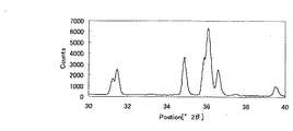
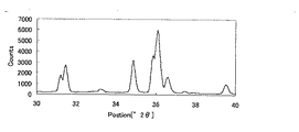
SCASN蛍光体の場合、上述の洗浄操作を行うことによって、Cu−Kα線(1.54184Å)を用いた粉末X線回折ピークのうち、2θ=33.2±0.2゜のピーク強度(高さ)比が低下する傾向にある。これは、洗浄を行うことによって、蛍光体から不純物が除去されていることを示している。
[Characteristics of phosphor]
(Powder X-ray diffraction pattern)
In the case of the SCASN phosphor, by performing the above-described cleaning operation, the peak intensity (high 2θ = 33.2 ± 0.2 °) of the powder X-ray diffraction peak using the Cu—Kα ray (1.54184Å) is high. The ratio tends to decrease. This indicates that impurities are removed from the phosphor by washing.
SCASN蛍光体の粉末X線回折パターンにおいて、2θが35.5゜〜37゜の範囲における最強ピークの高さImaxに対する、2θ=33.2゜±0.2゜のピークの高さIpの強度比をI=(Ip×100)/Imaxとするとき、Iは通常15%以下であり、好ましくは10%以下、より好ましくは5%以下、特に3%以下が好ましい。ここでピーク強度はバックグラウンド補正を行って得た値である。 In the powder X-ray diffraction pattern of the SCASN phosphor, the peak height I p of 2θ = 33.2 ° ± 0.2 ° with respect to the height I max of the strongest peak in the range of 2θ of 35.5 ° to 37 °. When I = (I p × 100) / I max , I is usually 15% or less, preferably 10% or less, more preferably 5% or less, and particularly preferably 3% or less. Here, the peak intensity is a value obtained by performing background correction.
(発光スペクトル)
例えば、本発明により得られるEu付活SCASN蛍光体は、橙色ないし赤色蛍光体としての用途に鑑みて、波長465nmの光で励起した場合における発光スペクトルを測定した場合に、以下の特徴を有することが好ましい。
(Emission spectrum)
For example, the Eu-activated SCASN phosphor obtained by the present invention has the following characteristics when an emission spectrum is measured when excited with light having a wavelength of 465 nm, in view of the use as an orange to red phosphor. Is preferred.
まず、本発明の蛍光体は、上述の発光スペクトルにおけるピーク波長λp(nm)が、通常590nmより大きく、中でも600nm以上、また、通常650nm以下、中でも640nm以下の範囲であることが好ましい。この発光ピーク波長λpが短過ぎると黄味を帯びる傾向がある一方で、長過ぎると暗赤味を帯びる傾向があり、何れも橙色ないし赤色光としての特性が低下するおそれがあるので好ましくない。 First, the phosphor of the present invention preferably has a peak wavelength λp (nm) in the above-described emission spectrum of usually greater than 590 nm, particularly 600 nm or more, and usually 650 nm or less, particularly 640 nm or less. If this emission peak wavelength λp is too short, it tends to be yellowish, whereas if it is too long, it tends to be dark reddish, both of which are not preferred because the characteristics as orange or red light may be reduced.
また、本発明の蛍光体は、上述の発光スペクトルにおける発光ピークの半値幅(full width at half maximum。以下適宜「FWHM」と略称する。)が、通常50nmより大きく、中でも70nm以上、更には75nm以上、また、通常120nm未満、中でも100nm以下、更には90nm以下の範囲であることが好ましい。この半値幅FWHMが狭過ぎると発光強度が低下するおそれがあり、広過ぎると色純度が低下するおそれがあるので、何れも好ましくない。 In addition, the phosphor of the present invention has a full width at half maximum (hereinafter, abbreviated as “FWHM” where appropriate) in the above-described emission spectrum, which is usually larger than 50 nm, particularly 70 nm or more, and even 75 nm. In addition, the thickness is preferably less than 120 nm, more preferably 100 nm or less, and even more preferably 90 nm or less. If the full width at half maximum FWHM is too narrow, the light emission intensity may be lowered, and if it is too wide, the color purity may be lowered.
なお、本発明の蛍光体を波長465nmの光で励起するには、例えば、GaN系発光ダイオードを用いることができる。また、本発明の蛍光体の発光スペクトルの測定、並びにその発光ピーク波長、ピーク相対強度及びピーク半値幅の算出は、例えば、日本分光社製蛍光測定装置等の装置を用いて行なうことができる。 In order to excite the phosphor of the present invention with light having a wavelength of 465 nm, for example, a GaN light emitting diode can be used. Moreover, the measurement of the emission spectrum of the phosphor of the present invention and the calculation of the emission peak wavelength, peak relative intensity and peak half-value width can be carried out using an apparatus such as a fluorescence measuring apparatus manufactured by JASCO Corporation.
(重量メジアン径D50)
本発明の蛍光体は、その重量メジアン径D50が、通常3μm以上、中でも5μm以上、また、通常30μm以下、中でも20μm以下の範囲であることが好ましい。重量メジアン径D50が小さすぎると、輝度が低下し、蛍光体粒子が凝集してしまう傾向があり好ましくない。一方、重量メジアン径D50が大きすぎると、塗布ムラやディスペンサー等の閉塞が生じる傾向があり好ましくない。
なお、本発明における蛍光体の重量メジアン径D50は、例えばレーザー回折/散乱式粒度分布測定装置等の装置を用いて測定することができる。
(Weight median diameter D 50 )
The phosphor of the present invention preferably has a weight median diameter D 50 in the range of usually 3 μm or more, especially 5 μm or more, and usually 30 μm or less, especially 20 μm or less. When the weight-average median diameter D 50 is too small, and the luminance decreases tends to phosphor particles tend to aggregate undesirably. On the other hand, when the weight-average median diameter D 50 is too large, there is a tendency for blockage, such as coating unevenness and dispenser is not preferable.
The weight-average median diameter D 50 of the phosphor in the present invention, for example, can be measured using a device such as a laser diffraction / scattering particle size distribution measuring apparatus.
(その他)
本発明の蛍光体は、その内部量子効率が高いほど好ましい。その値は、通常0.5以上、好ましくは0.6以上、更に好ましくは0.7以上である。内部量子効率が低いと発光効率が低下する傾向にあり、好ましくない。
(Other)
The phosphor of the present invention is more preferable as its internal quantum efficiency is higher. The value is usually 0.5 or more, preferably 0.6 or more, more preferably 0.7 or more. If the internal quantum efficiency is low, the light emission efficiency tends to decrease, which is not preferable.
本発明の蛍光体は、その吸収効率も高いほど好ましい。その値は通常0.5以上、好ましくは0.6以上、更に好ましくは0.7以上である。吸収効率が低いと発光効率が低下する傾向にあり、好ましくない。 The phosphor of the present invention is preferably as its absorption efficiency is high. The value is usually 0.5 or more, preferably 0.6 or more, more preferably 0.7 or more. If the absorption efficiency is low, the light emission efficiency tends to decrease, which is not preferable.
[蛍光体の用途]
本発明の蛍光体は、高輝度であり、演色性が高いという特性を生かして、各種の発光装置(後述する「本発明の発光装置」)に好適に用いることができる。例えば、本発明の蛍光体が、橙色ないし赤色蛍光体である場合、緑色蛍光体、青色蛍光体等を組み合わせれば、高演色性の白色発光装置を実現することができる。こうして得られた発光装置を、画像表示装置の発光部(特に液晶用バックライトなど)や照明装置として使用することができる。
[Use of phosphor]
The phosphor of the present invention can be suitably used for various light-emitting devices (hereinafter referred to as “light-emitting device of the present invention”) by taking advantage of its high luminance and high color rendering properties. For example, when the phosphor of the present invention is an orange or red phosphor, a high color rendering white light emitting device can be realized by combining a green phosphor, a blue phosphor, and the like. The light-emitting device thus obtained can be used as a light-emitting portion (particularly a liquid crystal backlight) or an illumination device of an image display device.
[蛍光体含有組成物]
本発明の蛍光体を発光装置等の用途に使用する場合には、これを液状媒体中に分散させた形態で用いることが好ましい。本発明の蛍光体を液状媒体中に分散させたものを、適宜「本発明の蛍光体含有組成物」と呼ぶものとする。
[Phosphor-containing composition]
When the phosphor of the present invention is used for a light emitting device or the like, it is preferably used in a form dispersed in a liquid medium. The phosphor of the present invention dispersed in a liquid medium will be referred to as “the phosphor-containing composition of the present invention” as appropriate.
本発明の蛍光体含有組成物に使用可能な液状媒体としては、所望の使用条件下において液状の性質を示し、本発明の蛍光体を好適に分散させると共に、好ましくない反応等を生じないものであれば、任意のものを目的等に応じて選択することが可能である。液状媒体の例としては、硬化前の熱硬化性樹脂、光硬化性樹脂が挙げられ、例えば、付加反応型シリコーン樹脂、縮合反応型シリコーン樹脂、変性シリコーン樹脂、エポキシ樹脂等が挙げられる。また、無機系材料、例えば、セラミック前駆体ポリマー若しくは金属アルコキシドを含有する溶液をゾル−ゲル法により加水分解重合して成る溶液を用いることができる。これらの液状媒体は一種を単独で使用してもよく、二種以上を任意の組み合わせ及び比率で併用してもよい。 The liquid medium that can be used in the phosphor-containing composition of the present invention is a liquid medium that exhibits liquid properties under the desired use conditions, and that suitably disperses the phosphor of the present invention and does not cause undesirable reactions. If there is, it is possible to select an arbitrary one according to the purpose. Examples of the liquid medium include a thermosetting resin and a photocurable resin before curing, and examples thereof include an addition reaction type silicone resin, a condensation reaction type silicone resin, a modified silicone resin, and an epoxy resin. In addition, a solution obtained by hydrolytic polymerization of a solution containing an inorganic material, for example, a ceramic precursor polymer or a metal alkoxide by a sol-gel method can be used. These liquid media may be used individually by 1 type, and may use 2 or more types together by arbitrary combinations and a ratio.
液状媒体の使用量は、用途等に応じて適宜調整すればよいが、一般的には、本発明の蛍光体に対する液状媒体の重量比で、通常3重量%以上、好ましくは5重量%以上、また、通常30重量%以下、好ましくは15重量%以下の範囲である。 The amount of the liquid medium used may be appropriately adjusted according to the application, etc., but in general, the weight ratio of the liquid medium to the phosphor of the present invention is usually 3% by weight or more, preferably 5% by weight or more, Moreover, it is 30 weight% or less normally, Preferably it is the range of 15 weight% or less.
また、本発明の蛍光体含有組成物は、本発明の蛍光体及び液状媒体に加え、その用途等に応じて、その他の任意の成分を含有していてもよい。その他の成分としては、拡散剤、増粘剤、増量剤、干渉剤等が挙げられる。具体的には、アエロジル等のシリカ系微粉、アルミナ等が挙げられる。 In addition to the phosphor of the present invention and the liquid medium, the phosphor-containing composition of the present invention may contain other optional components depending on its use and the like. Examples of other components include a diffusing agent, a thickener, a bulking agent, and an interference agent. Specifically, silica-based fine powder such as Aerosil, alumina and the like can be mentioned.
[発光装置]
次に、本発明の発光装置について説明する。本発明の発光装置は、励起光源としての第1の発光体と、第1の発光体からの光の照射によって可視光を発する第2の発光体とを、少なくとも備えて構成される。
[Light emitting device]
Next, the light emitting device of the present invention will be described. The light-emitting device of the present invention includes at least a first light-emitting body as an excitation light source and a second light-emitting body that emits visible light when irradiated with light from the first light-emitting body.
(第1の発光体)
本発明の発光装置における第1の発光体は、後述する第2の発光体を励起する光を発光するものである。第1の発光体の発光波長は、後述する第2の発光体の吸収波長と重複するものであれば、特に制限されず、幅広い発光波長領域の発光体を使用することができる。通常は、近紫外領域から青色領域までの発光波長を有する発光体が使用され、具体的数値としては、通常300nm以上、好ましくは330nm以上、また、通常500nm以下、好ましくは480nm以下のピーク発光波長を有する発光体が使用される。この第1の発光体としては、一般的には半導体発光素子が用いられ、具体的には発光ダイオード(light emitting diode。以下、適宜「LED」と略称する。)や半導体レーザーダイオード(semiconductor laser diode。以下、適宜「LD」と略称する。)等が使用できる。
(First luminous body)
The 1st light-emitting body in the light-emitting device of this invention light-emits the light which excites the 2nd light-emitting body mentioned later. The light emission wavelength of the first light emitter is not particularly limited as long as it overlaps with the absorption wavelength of the second light emitter described later, and a light emitter having a wide light emission wavelength region can be used. Usually, an illuminant having an emission wavelength from the near ultraviolet region to the blue region is used, and the specific numerical value is usually 300 nm or more, preferably 330 nm or more, and usually 500 nm or less, preferably 480 nm or less. A light emitter having the following is used. As the first light emitter, a semiconductor light emitting element is generally used. Specifically, a light emitting diode (hereinafter abbreviated as “LED” as appropriate) or a semiconductor laser diode (semiconductor laser diode). Hereinafter, it is abbreviated as “LD” where appropriate).
中でも、第1の発光体としては、GaN系化合物半導体を使用したGaN系LEDやLDが好ましい。なぜなら、GaN系LEDやLDは、この領域の光を発するSiC系LED等に比し、発光出力や外部量子効率が格段に大きく、前記蛍光体と組み合わせることによって、非常に低電力で非常に明るい発光が得られるからである。例えば、20mAの電流負荷に対し、通常GaN系LEDやLDはSiC系の100倍以上の発光強度を有する。GaN系LEDやLDにおいては、AlXGaYN発光層、GaN発光層、又はInXGaYN発光層を有しているものが好ましい。GaN系LEDにおいては、それらの中でInXGaYN発光層を有するものが発光強度が非常に強いので、特に好ましく、GaN系LDにおいては、InXGaYN層とGaN層の多重量子井戸構造のものが発光強度が非常に強いので、特に好ましい。 Among these, as the first light emitter, a GaN LED or LD using a GaN compound semiconductor is preferable. This is because GaN-based LEDs and LDs have significantly higher light emission output and external quantum efficiency than SiC-based LEDs that emit light in this region, and are extremely bright with very low power when combined with the phosphor. This is because light emission can be obtained. For example, for a current load of 20 mA, GaN-based LEDs and LDs usually have a light emission intensity 100 times or more that of SiC-based. GaN-based LEDs and LDs preferably have an Al X Ga Y N light emitting layer, a GaN light emitting layer, or an In X Ga Y N light emitting layer. Among the GaN-based LEDs, those having an In X Ga Y N light-emitting layer are particularly preferable because the emission intensity is very strong, and in the GaN-based LD, the multiple quantum of the In X Ga Y N layer and the GaN layer is preferable. A well structure is particularly preferable because the emission intensity is very strong.
なお、上記においてX+Yの値は通常0.8〜1.2の範囲の値である。GaN系LEDにおいて、これら発光層にZnやSiをドープしたものやドーパント無しのものが発光特性を調節する上で好ましいものである。 In the above, the value of X + Y is usually a value in the range of 0.8 to 1.2. In the GaN-based LED, those in which the light emitting layer is doped with Zn or Si or those without a dopant are preferable for adjusting the light emission characteristics.
GaN系LEDはこれら発光層、p層、n層、電極、及び基板を基本構成要素としたものであり、発光層をn型とp型のAlXGaYN層、GaN層、又はInXGaYN層などでサンドイッチにしたヘテロ構造を有しているものが、発光効率が高く、好ましく、さらにヘテロ構造を量子井戸構造にしたものが、発光効率がさらに高く、より好ましい。 A GaN-based LED has these light-emitting layer, p-layer, n-layer, electrode, and substrate as basic components, and the light-emitting layer is an n-type and p-type Al X Ga Y N layer, GaN layer, or In X Those having a hetero structure sandwiched between Ga Y N layers and the like have high luminous efficiency, and those having a hetero structure having a quantum well structure further have high luminous efficiency and are more preferable.
(第2の発光体)
本発明の発光装置における第2の発光体は、上述した第1の発光体からの光の照射によって可視光を発する発光体であり、後述する第1の蛍光体(橙色ないし赤色蛍光体)を含有するとともに、その用途等に応じて適宜、後述する第2の蛍光体(緑色蛍光体、青色蛍光体等)を含有する。
(Second light emitter)
The second light emitter in the light emitting device of the present invention is a light emitter that emits visible light when irradiated with light from the first light emitter described above, and a first phosphor (orange or red phosphor) to be described later is used. A second phosphor (a green phosphor, a blue phosphor, etc.) to be described later is contained as appropriate according to the application.
蛍光体の組成には特に制限はないが、結晶母体であるY2O3、Zn2SiO4等に代表される金属酸化物、Sr2Si5N8等に代表される金属窒化物、Ca5(PO4)3Cl等に代表されるリン酸塩及びZnS、SrS、CaS等に代表される硫化物に、Ce、Pr、Nd、Pm、Sm、Eu、Tb、Dy、Ho、Er、Tm、Yb等の希土類金属のイオンやAg、Cu、Au、Al、Mn、Sb等の金属のイオンを付活元素又は共付活元素として組み合わせたものが好ましい。
There is no particular limitation on the composition of the phosphor, Y 2 O 3 is a host crystal, Zn 2 metal oxide represented by SiO 4 and the like, a metal nitride typified by
結晶母体の好ましい例としては、例えば、(Zn,Cd)S、SrGa2S4、SrS、ZnS等の硫化物、Y2O2S等の酸硫化物、(Y,Gd)3Al5O12、YAlO3、BaMgAl10O17、(Ba,Sr)(Mg,Mn)Al10O17、(Ba,Sr,Ca)(Mg,Zn,Mn)Al10O17、BaAl12O19、CeMgAl11O19、(Ba,Sr,Mg)O・Al2O3、BaAl2Si2O8、SrAl2O4、Sr4Al14O25、Y3Al5O12等のアルミン酸塩、Y2SiO5、Zn2SiO4等の珪酸塩、SnO2、Y2O3等の酸化物、GdMgB5O10、(Y,Gd)BO3等の硼酸塩、Ca10(PO4)6(F,Cl)2、(Sr,Ca,Ba,Mg)10(PO4)6Cl2等のハロリン酸塩、Sr2P2O7、(La,Ce)PO4等のリン酸塩等を挙げることができる。 Preferred examples of the crystal matrix include sulfides such as (Zn, Cd) S, SrGa 2 S 4 , SrS, and ZnS, oxysulfides such as Y 2 O 2 S, and (Y, Gd) 3 Al 5 O. 12 , YAlO 3 , BaMgAl 10 O 17 , (Ba, Sr) (Mg, Mn) Al 10 O 17 , (Ba, Sr, Ca) (Mg, Zn, Mn) Al 10 O 17 , BaAl 12 O 19 , CeMgAl 11 O 19 , (Ba, Sr, Mg) O.Al 2 O 3 , BaAl 2 Si 2 O 8 , SrAl 2 O 4 , Sr 4 Al 14 O 25 , aluminate such as Y 3 Al 5 O 12 , Y Silicates such as 2 SiO 5 and Zn 2 SiO 4 , oxides such as SnO 2 and Y 2 O 3 , borates such as GdMgB 5 O 10 and (Y, Gd) BO 3 , Ca 10 (PO 4 ) 6 ( F, Cl) 2, (Sr , Ca, Ba, g) 10 (PO 4) such as 6 Cl 2 halophosphate, Sr 2 P 2 O 7, can be cited (La, Ce) phosphate PO 4, etc. and the like.
ただし、上記の結晶母体及び付活元素又は共付活元素は、元素組成には特に制限はなく、同族の元素と一部置き換えることもでき、得られた蛍光体は近紫外から可視領域の光を吸収して可視光を発するものであれば用いることが可能である。 However, the crystal matrix and the activator element or coactivator element are not particularly limited in element composition, and can be partially replaced with elements of the same family, and the obtained phosphor is light in the near ultraviolet to visible region. Any material that absorbs and emits visible light can be used.
具体的には、蛍光体として以下に挙げるものを用いることが可能であるが、これらはあくまでも例示であり、本発明で使用できる蛍光体はこれらに限られるものではない。なお、以下の例示では、構造の一部のみが異なる蛍光体を、適宜省略して示している。例えば、「Y2SiO5:Ce3+」、「Y2SiO5:Tb3+」及び「Y2SiO5:Ce3+,Tb3+」を「Y2SiO5:Ce3+,Tb3+」と、「La2O2S:Eu」、「Y2O2S:Eu」及び「(La,Y)2O2S:Eu」を「(La,Y)2O2S:Eu」とまとめて示している。省略箇所はカンマ(,)で区切って示す。 Specifically, the following phosphors can be used, but these are merely examples, and phosphors that can be used in the present invention are not limited to these. In the following examples, phosphors that differ only in part of the structure are omitted as appropriate. For example, “Y 2 SiO 5 : Ce 3+ ”, “Y 2 SiO 5 : Tb 3+ ” and “Y 2 SiO 5 : Ce 3+ , Tb 3+ ” are changed to “Y 2 SiO 5 : Ce 3+ , Tb 3+ ”, “ “La 2 O 2 S: Eu”, “Y 2 O 2 S: Eu” and “(La, Y) 2 O 2 S: Eu” are collectively shown as “(La, Y) 2 O 2 S: Eu”. ing. Omitted parts are shown separated by commas (,).
<第1の蛍光体(橙色ないし赤色蛍光体)>
本発明の発光装置における第2の発光体は、橙色ないし赤色蛍光体(これを以下適宜「第1の蛍光体」と呼ぶ。)として、少なくとも上述の本発明の蛍光体を含有する。本発明の蛍光体は、何れか一種を単独で使用してもよく、二種以上を任意の組み合わせ及び比率で併用してもよい。また、本発明の蛍光体以外に、その他の一種又は二種以上の橙色ないし赤色蛍光体を、第1の蛍光体として併用してもよい。
<First phosphor (orange to red phosphor)>
The second light emitter in the light emitting device of the present invention contains at least the above-described phosphor of the present invention as an orange to red phosphor (hereinafter referred to as “first phosphor” as appropriate). Any one of the phosphors of the present invention may be used alone, or two or more thereof may be used in any combination and ratio. In addition to the phosphor of the present invention, one or more other orange or red phosphors may be used in combination as the first phosphor.
赤色の蛍光を発する蛍光体(以下適宜、「赤色蛍光体」という)が発する蛍光の具体的な波長の範囲を例示すると、ピーク波長が、通常570nm以上、好ましくは580nm以上、また、通常700nm以下、好ましくは680nm以下が望ましい。 Illustrating the specific wavelength range of the fluorescence emitted by the phosphor emitting red fluorescence (hereinafter referred to as “red phosphor” as appropriate), the peak wavelength is usually 570 nm or more, preferably 580 nm or more, and usually 700 nm or less. Preferably, it is 680 nm or less.
本発明の蛍光体以外の橙色ないし赤色蛍光体としては、例えば、赤色破断面を有する破断粒子から構成され、赤色領域の発光を行なう(Mg,Ca,Sr,Ba)2Si5N8:Euで表わされるユウロピウム付活アルカリ土類シリコンナイトライド系蛍光体、規則的な結晶成長形状としてほぼ球形状を有する成長粒子から構成され、赤色領域の発光を行なう(Y,La,Gd,Lu)2O2S:Euで表わされるユウロピウム付活希土類オキシカルコゲナイド系蛍光体等が挙げられる。 The orange or red phosphor other than the phosphor of the present invention is composed of, for example, fractured particles having a red fracture surface and emits light in a red region (Mg, Ca, Sr, Ba) 2 Si 5 N 8 : Eu Europium-activated alkaline earth silicon nitride phosphor expressed by the following formula: growth particles having a substantially spherical shape as a regular crystal growth shape, and emitting light in the red region (Y, La, Gd, Lu) 2 Examples include europium activated rare earth oxychalcogenide phosphors represented by O 2 S: Eu.
さらに、特開2004−300247号公報に記載された、Ti、Zr、Hf、Nb、Ta、W、及びMoよりなる群から選ばれる少なくも1種の元素を含有する酸窒化物及び/又は酸硫化物を含有する蛍光体であって、Al元素の一部又は全てがGa元素で置換されたアルファサイアロン構造をもつ酸窒化物を含有する蛍光体も、本実施形態において用いることができる。なお、これらは酸窒化物及び/又は酸硫化物を含有する蛍光体である。 Furthermore, the oxynitride and / or acid containing at least one element selected from the group consisting of Ti, Zr, Hf, Nb, Ta, W, and Mo described in JP-A-2004-300247 A phosphor containing a sulfide and containing an oxynitride having an alpha sialon structure in which a part or all of the Al element is substituted with a Ga element can also be used in this embodiment. These are phosphors containing oxynitride and / or oxysulfide.
また、そのほか、赤色蛍光体としては、(La,Y)2O2S:Eu等のEu付活酸硫化物蛍光体、Y(V,P)O4:Eu、Y2O3:Eu等のEu付活酸化物蛍光体、(Ba,Sr,Ca,Mg)2SiO4:Eu,Mn、(Ba,Mg)2SiO4:Eu,Mn等のEu,Mn付活珪酸塩蛍光体、(Ca,Sr)S:Eu等のEu付活硫化物蛍光体、YAlO3:Eu等のEu付活アルミン酸塩蛍光体、LiY9(SiO4)6O2:Eu、Ca2Y8(SiO4)6O2:Eu、(Sr,Ba,Ca)3SiO5:Eu、Sr2BaSiO5:Eu等のEu付活珪酸塩蛍光体、(Y,Gd)3Al5O12:Ce、(Tb,Gd)3Al5O12:Ce等のCe付活アルミン酸塩蛍光体、(Ca,Sr,Ba)2Si5N8:Eu、(Mg,Ca,Sr,Ba)SiN2:Eu、(Mg,Ca,Sr,Ba)AlSiN3:Eu等のEu付活窒化物蛍光体、(Mg,Ca,Sr,Ba)AlSiN3:Ce等のCe付活窒化物蛍光体、(Sr,Ca,Ba,Mg)10(PO4)6Cl2:Eu,Mn等のEu,Mn付活ハロリン酸塩蛍光体、(Ba3Mg)Si2O8:Eu,Mn、(Ba,Sr,Ca,Mg)3(Zn,Mg)Si2O8:Eu,Mn等のEu,Mn付活珪酸塩蛍光体、3.5MgO・0.5MgF2・GeO2:Mn等のMn付活ゲルマン酸塩蛍光体、Eu付活αサイアロン等のEu付活酸窒化物蛍光体、(Gd,Y,Lu,La)2O3:Eu,Bi等のEu,Bi付活酸化物蛍光体、(Gd,Y,Lu,La)2O2S:Eu,Bi等のEu,Bi付活酸硫化物蛍光体、(Gd,Y,Lu,La)VO4:Eu,Bi等のEu,Bi付活バナジン酸塩蛍光体、SrY2S4:Eu,Ce等のEu,Ce付活硫化物蛍光体、CaLa2S4:Ce等のCe付活硫化物蛍光体、(Ba,Sr,Ca)MgP2O7:Eu,Mn、(Sr,Ca,Ba,Mg,Zn)2P2O7:Eu,Mn等のEu,Mn付活リン酸塩蛍光体、(Y,Lu)2WO6:Eu,Mo等のEu,Mo付活タングステン酸塩蛍光体、(Ba,Sr,Ca)xSiyNz:Eu,Ce(但し、x、y、zは、1以上の整数)等のEu,Ce付活窒化物蛍光体、(Ca,Sr,Ba,Mg)10(PO4)6(F,Cl,Br,OH):Eu,Mn等のEu,Mn付活ハロリン酸塩蛍光体、((Y,Lu,Gd,Tb)1−xScxCey)2(Ca,Mg)1−r(Mg,Zn)2+rSiz−qGeqO12+δ等のCe付活珪酸塩蛍光体等を用いることも可能である。 In addition, examples of red phosphors include Eu-activated oxysulfide phosphors such as (La, Y) 2 O 2 S: Eu, Y (V, P) O 4 : Eu, Y 2 O 3 : Eu, and the like. Eu-activated oxide phosphor, (Ba, Sr, Ca, Mg) 2 SiO 4: Eu, Mn, (Ba, Mg) 2 SiO 4: Eu, Eu such as Mn, Mn-activated silicate phosphor, (Ca, Sr) S: Eu-activated sulfide phosphors such as Eu, YAlO 3 : Eu-activated aluminate phosphors such as Eu, LiY 9 (SiO 4 ) 6 O 2 : Eu, Ca 2 Y 8 ( SiO 4 ) 6 O 2 : Eu, (Sr, Ba, Ca) 3 SiO 5 : Eu, Sr 2 BaSiO 5 : Eu-activated silicate phosphor such as Eu, (Y, Gd) 3 Al 5 O 12 : Ce , (Tb, Gd) 3 Al 5 O 12: Ce -activated aluminate phosphor such as Ce, (Ca, Sr, Ba ) 2 Si 5 8: Eu, (Mg, Ca , Sr, Ba) SiN 2: Eu, (Mg, Ca, Sr, Ba) AlSiN 3: Eu -activated nitride phosphor such as Eu, (Mg, Ca, Sr , Ba) AlSiN 3 : Ce-activated nitride phosphor such as Ce, (Sr, Ca, Ba, Mg) 10 (PO 4 ) 6 Cl 2 : Eu, Mn-activated halophosphate phosphor such as Eu and Mn, (Ba 3 Mg) Si 2 O 8 : Eu, Mn, (Ba, Sr, Ca, Mg) 3 (Zn, Mg) Si 2 O 8 : Eu, Mn activated silicate phosphor such as Eu, Mn, 3.5MgO 0.5MgF 2 · GeO 2 : Mn-activated germanate phosphor such as Mn, Eu-activated oxynitride phosphor such as Eu-activated α-sialon, (Gd, Y, Lu, La) 2 O 3 : eu, eu Bi, etc., Bi-activated oxide phosphor, (Gd, Y, Lu, La) 2 O 2 S: Eu, Bi Of Eu, Bi Tsukekatsusan sulfide phosphor, (Gd, Y, Lu, La) VO 4: Eu, Eu Bi, etc., Bi-activated vanadate phosphor, SrY 2 S 4: Eu, such as Ce Eu, Ce activated sulfide phosphor, Ce activated sulfide phosphor such as CaLa 2 S 4 : Ce, (Ba, Sr, Ca) MgP 2 O 7 : Eu, Mn, (Sr, Ca, Ba, Mg) , Zn) 2 P 2 O 7 : Eu, Mn activated phosphor phosphor such as Eu, Mn, (Y, Lu) 2 WO 6 : Eu, Mo activated tungstate phosphor such as Eu, Mo, (Ba, Sr, Ca) x Si y N z : Eu, Ce activated nitride phosphor such as Eu, Ce (where x, y, z are integers of 1 or more), (Ca, Sr, Ba, mg) 10 (PO 4) 6 (F, Cl, Br, OH): Eu, Eu such as Mn, Mn-activated halophosphate phosphor, ((Y, Lu, d, Tb) can also be used such as 1-x Sc x Ce y) 2 (Ca, Mg) 1-r (Mg, Zn) 2 + r Si z-q GeqO Ce -activated silicate phosphors 12 + [delta], etc. .
赤色蛍光体としては、β−ジケトネート、β−ジケトン、芳香族カルボン酸、又は、ブレンステッド酸等のアニオンを配位子とする希土類元素イオン錯体からなる赤色有機蛍光体、ペリレン系顔料(例えば、ジベンゾ{[f,f’]−4,4’,7,7’−テトラフェニル}ジインデノ[1,2,3−cd:1’,2’,3’−lm]ペリレン)、アントラキノン系顔料、レーキ系顔料、アゾ系顔料、キナクリドン系顔料、アントラセン系顔料、イソインドリン系顔料、イソインドリノン系顔料、フタロシアニン系顔料、トリフェニルメタン系塩基性染料、インダンスロン系顔料、インドフェノール系顔料、シアニン系顔料、ジオキサジン系顔料を用いることも可能である。 As the red phosphor, β-diketonate, β-diketone, aromatic carboxylic acid, or a red organic phosphor composed of a rare earth element ion complex having an anion such as Bronsted acid as a ligand, a perylene pigment (for example, Dibenzo {[f, f ′]-4,4 ′, 7,7′-tetraphenyl} diindeno [1,2,3-cd: 1 ′, 2 ′, 3′-lm] perylene), anthraquinone pigment, Lake pigments, azo pigments, quinacridone pigments, anthracene pigments, isoindoline pigments, isoindolinone pigments, phthalocyanine pigments, triphenylmethane basic dyes, indanthrone pigments, indophenol pigments, It is also possible to use a cyanine pigment or a dioxazine pigment.
また、赤色蛍光体のうち、ピーク波長が580nm以上、好ましくは590nm以上、また、620nm以下、好ましくは610nm以下の範囲内にあるものは、橙色蛍光体として好適に用いることができる。このような橙色蛍光体の例としては、(Sr,Ba)3SiO5:Eu、(Sr,Mg)3(PO4)2:Sn2+等が挙げられる。 Among the red phosphors, those having a peak wavelength in the range of 580 nm or more, preferably 590 nm or more, and 620 nm or less, preferably 610 nm or less can be suitably used as the orange phosphor. Examples of such orange phosphors include (Sr, Ba) 3 SiO 5 : Eu, (Sr, Mg) 3 (PO 4 ) 2 : Sn 2+, and the like.
<第2の蛍光体>
更に、本発明の発光装置における第2の発光体は、その用途に応じて、上述の第1の蛍光体(本発明の蛍光体)とは発光波長の異なる蛍光体を含有していてもよい(これを以下適宜「第2の蛍光体」と呼ぶ。)。第2の蛍光体としては、一種類の蛍光体を単独で使用してもよく、二種以上の蛍光体を任意の組み合わせ及び比率で併用してもよい。
<Second phosphor>
Furthermore, the 2nd light-emitting body in the light-emitting device of this invention may contain the fluorescent substance from which an emission wavelength differs from the above-mentioned 1st fluorescent substance (phosphor of this invention) according to the use. (This is hereinafter referred to as “second phosphor” as appropriate). As the second phosphor, one kind of phosphor may be used alone, or two or more kinds of phosphors may be used in any combination and ratio.
第1の蛍光体(橙色ないし赤色蛍光体)と併用する第2の蛍光体の例としては、緑色の発光を発する蛍光体(以下適宜「緑色蛍光体」という。)、及び、青色の発光を発する蛍光体(以下適宜「青色蛍光体」という。)が挙げられる。 Examples of the second phosphor used in combination with the first phosphor (orange to red phosphor) include phosphors emitting green light (hereinafter referred to as “green phosphors” as appropriate) and blue light emission. And a phosphor that emits light (hereinafter referred to as “blue phosphor” as appropriate).
{緑色蛍光体}
緑色の蛍光を発する蛍光体(以下適宜、「緑色蛍光体」という)が発する蛍光の具体的な波長の範囲を例示すると、ピーク波長が、通常490nm以上、好ましくは500nm以上、また、通常570nm以下、好ましくは550nm以下が望ましい。
{Green phosphor}
When a specific wavelength range of fluorescence emitted by a phosphor emitting green fluorescence (hereinafter referred to as “green phosphor” as appropriate) is exemplified, the peak wavelength is usually 490 nm or more, preferably 500 nm or more, and usually 570 nm or less. Preferably, it is 550 nm or less.
このような緑色蛍光体として、例えば、破断面を有する破断粒子から構成され、緑色領域の発光を行なう(Mg,Ca,Sr,Ba)Si2O2N2:Euで表わされるユウロピウム付活アルカリ土類シリコンオキシナイトライド系蛍光体、破断面を有する破断粒子から構成され、緑色領域の発光を行なう(Ba,Ca,Sr,Mg)2SiO4:Euで表わされるユウロピウム付活アルカリ土類シリケート系蛍光体等が挙げられる。 As such a green phosphor, for example, a europium-activated alkali represented by (Mg, Ca, Sr, Ba) Si 2 O 2 N 2 : Eu that is composed of fractured particles having a fracture surface and emits light in the green region. Europium-activated alkaline earth silicate composed of an earth silicon oxynitride phosphor, broken particles having a fracture surface, and emitting in the green region (Ba, Ca, Sr, Mg) 2 SiO 4 : Eu System phosphors and the like.
また、そのほか、緑色蛍光体としては、Sr4Al14O25:Eu、(Ba,Sr,Ca)Al2O4:Eu等のEu付活アルミン酸塩蛍光体、(Sr,Ba)Al2Si2O8:Eu、(Ba,Mg)2SiO4:Eu、(Ba,Sr,Ca,Mg)2SiO4:Eu、(Ba,Sr,Ca)2(Mg,Zn)Si2O7:Eu等のEu付活珪酸塩蛍光体、Y2SiO5:Ce,Tb等のCe,Tb付活珪酸塩蛍光体、Sr2P2O7−Sr2B2O5:Eu等のEu付活硼酸リン酸塩蛍光体、Sr2Si3O8−2SrCl2:Eu等のEu付活ハロ珪酸塩蛍光体、Zn2SiO4:Mn等のMn付活珪酸塩蛍光体、CeMgAl11O19:Tb、Y3Al5O12:Tb等のTb付活アルミン酸塩蛍光体、Ca2Y8(SiO4)6O2:Tb、La3Ga5SiO14:Tb等のTb付活珪酸塩蛍光体、(Sr,Ba,Ca)Ga2S4:Eu,Tb,Sm等のEu,Tb,Sm付活チオガレート蛍光体、Y3(Al,Ga)5O12:Ce、(Y,Ga,Tb,La,Sm,Pr,Lu)3(Al,Ga)5O12:Ce等のCe付活アルミン酸塩蛍光体、Ca3Sc2Si3O12:Ce、Ca3(Sc,Mg,Na,Li)2Si3O12:Ce等のCe付活珪酸塩蛍光体、CaSc2O4:Ce等のCe付活酸化物蛍光体、SrSi2O2N2:Eu、(Sr,Ba,Ca)Si2O2N2:Eu、Eu付活βサイアロン、Eu付活αサイアロン等のEu付活酸窒化物蛍光体、BaMgAl10O17:Eu,Mn等のEu,Mn付活アルミン酸塩蛍光体、SrAl2O4:Eu等のEu付活アルミン酸塩蛍光体、(La,Gd,Y)2O2S:Tb等のTb付活酸硫化物蛍光体、LaPO4:Ce,Tb等のCe,Tb付活リン酸塩蛍光体、ZnS:Cu,Al、ZnS:Cu,Au,Al等の硫化物蛍光体、(Y,Ga,Lu,Sc,La)BO3:Ce,Tb、Na2Gd2B2O7:Ce,Tb、(Ba,Sr)2(Ca,Mg,Zn)B2O6:K,Ce,Tb等のCe,Tb付活硼酸塩蛍光体、Ca8Mg(SiO4)4Cl2:Eu,Mn等のEu,Mn付活ハロ珪酸塩蛍光体、(Sr,Ca,Ba)(Al,Ga,In)2S4:Eu等のEu付活チオアルミネート蛍光体やチオガレート蛍光体、(Ca,Sr)8(Mg,Zn)(SiO4)4Cl2:Eu,Mn等のEu,Mn付活ハロ珪酸塩蛍光体等を用いることも可能である。 In addition, as the green phosphor, Eu-activated aluminate phosphor such as Sr 4 Al 14 O 25 : Eu, (Ba, Sr, Ca) Al 2 O 4 : Eu, (Sr, Ba) Al 2 Si 2 O 8 : Eu, (Ba, Mg) 2 SiO 4 : Eu, (Ba, Sr, Ca, Mg) 2 SiO 4 : Eu, (Ba, Sr, Ca) 2 (Mg, Zn) Si 2 O 7 : Eu activated silicate phosphor such as Eu, Y 2 SiO 5 : Ce, Tb activated silicate phosphor such as Ce, Tb, Sr 2 P 2 O 7 —Sr 2 B 2 O 5 : Eu such as Eu Activated boric acid phosphor, Sr 2 Si 3 O 8 -2SrCl 2 : Eu activated halosilicate phosphor such as Eu, Zn 2 SiO 4 : Mn activated silicate phosphor such as Mn, CeMgAl 11 O 19: Tb, Y 3 Al 5 O 12: Tb -activated aluminate Sanshiohotaru of Tb such Body, Ca 2 Y 8 (SiO 4 ) 6 O 2: Tb, La 3 Ga 5 SiO 14: Tb -activated silicate phosphors such as Tb, (Sr, Ba, Ca ) Ga 2 S 4: Eu, Tb, Eu, Tb, Sm activated thiogallate phosphors such as Sm, Y 3 (Al, Ga) 5 O 12 : Ce, (Y, Ga, Tb, La, Sm, Pr, Lu) 3 (Al, Ga) 5 O 12 : Ce-activated aluminate phosphor such as Ce, Ca 3 Sc 2 Si 3 O 12 : Ce, Ca 3 (Sc, Mg, Na, Li) 2 Si 3 O 12 : Ce-activated silicate such as Ce Phosphor, Ce activated oxide phosphor such as CaSc 2 O 4 : Ce, SrSi 2 O 2 N 2 : Eu, (Sr, Ba, Ca) Si 2 O 2 N 2 : Eu, Eu activated β sialon, Eu-activated oxynitride phosphors such as Eu-activated α sialon, BaMgAl 10 O 17 : Eu, Mn activated aluminate phosphor such as Eu, Mn, SrAl 2 O 4 : Eu activated aluminate phosphor such as Eu, (La, Gd, Y) 2 O 2 S: Tb such as Tb Activated oxysulfide phosphor, LaPO 4 : Ce, Tb activated phosphate phosphor such as Ce, Tb, Sulfide phosphor such as ZnS: Cu, Al, ZnS: Cu, Au, Al, (Y, Ga, Lu, Sc, La) BO 3: Ce, Tb, Na 2 Gd 2 B 2 O 7: Ce, Tb, (Ba, Sr) 2 (Ca, Mg, Zn) B 2 O 6: K, Ce, Ce, Tb activated borate phosphor such as Tb, Eu, Mn activated halosilicate phosphor such as Ca 8 Mg (SiO 4 ) 4 Cl 2 : Eu, Mn, (Sr, Ca, Ba) (Al, Ga, in) 2 S 4: Eu activated thioaluminate phosphor or thiogallate phosphor such as Eu, (Ca, Sr) 8 (M , Zn) (SiO 4) 4 Cl 2: Eu, it is also possible to use Eu such as Mn, a Mn-activated halo-silicate phosphors and the like.
また、緑色蛍光体としては、ピリジン−フタルイミド縮合誘導体、ベンゾオキサジノン系、キナゾリノン系、クマリン系、キノフタロン系、ナルタル酸イミド系等の蛍光色素、テルビウム錯体等の有機蛍光体を用いることも可能である。 In addition, as the green phosphor, it is also possible to use a pyridine-phthalimide condensed derivative, a benzoxazinone-based, a quinazolinone-based, a coumarin-based, a quinophthalone-based, a naltalimide-based fluorescent pigment, or an organic phosphor such as a terbium complex. is there.
{青色蛍光体}
青色の蛍光を発する蛍光体(以下適宜、「青色蛍光体」という)が発する蛍光の具体的な波長の範囲を例示すると、ピーク波長が、通常420nm以上、好ましくは440nm以上、また、通常480nm以下、好ましくは470nm以下が望ましい。
{Blue phosphor}
Illustrating the specific wavelength range of the fluorescence emitted by a phosphor emitting blue fluorescence (hereinafter referred to as “blue phosphor” as appropriate), the peak wavelength is usually 420 nm or more, preferably 440 nm or more, and usually 480 nm or less. Preferably, it is 470 nm or less.
このような青色蛍光体としては、規則的な結晶成長形状としてほぼ六角形状を有する成長粒子から構成され、青色領域の発光を行なうBaMgAl10O17:Euで表わされるユウロピウム付活バリウムマグネシウムアルミネート系蛍光体、規則的な結晶成長形状としてほぼ球形状を有する成長粒子から構成され、青色領域の発光を行なう(Ca,Sr,Ba)5(PO4)3Cl:Euで表わされるユウロピウム付活ハロリン酸カルシウム系蛍光体、規則的な結晶成長形状としてほぼ立方体形状を有する成長粒子から構成され、青色領域の発光を行なう(Ca,Sr,Ba)2B5O9Cl:Euで表わされるユウロピウム付活アルカリ土類クロロボレート系蛍光体、破断面を有する破断粒子から構成され、青緑色領域の発光を行なう(Sr,Ca,Ba)Al2O4:Eu又は(Sr,Ca,Ba)4Al14O25:Euで表わされるユウロピウム付活アルカリ土類アルミネート系蛍光体等が挙げられる。 As such a blue phosphor, a europium-activated barium magnesium aluminate system represented by BaMgAl 10 O 17 : Eu, which is composed of growing particles having a substantially hexagonal shape as a regular crystal growth shape and emits light in a blue region. Europium activated halo represented by (Ca, Sr, Ba) 5 (PO 4 ) 3 Cl: Eu, which is composed of phosphors and growing particles having a substantially spherical shape as a regular crystal growth shape, and emits light in the blue region. Calcium phosphate-based phosphor, composed of growing particles having a cubic shape as a regular crystal growth shape, emits light in the blue region, and is activated by europium represented by (Ca, Sr, Ba) 2 B 5 O 9 Cl: Eu Consists of alkaline earth chloroborate phosphors and fractured particles with fractured surfaces, and emits light in the blue-green region Examples include europium-activated alkaline earth aluminate-based phosphors represented by (Sr, Ca, Ba) Al 2 O 4 : Eu or (Sr, Ca, Ba) 4 Al 14 O 25 : Eu.
また、そのほか、青色蛍光体としては、Sr2P2O7:Sn等のSn付活リン酸塩蛍光体、Sr4Al14O25:Eu、BaMgAl10O17:Eu、BaAl8O13:Eu等のEu付活アルミン酸塩蛍光体、SrGa2S4:Ce、CaGa2S4:Ce等のCe付活チオガレート蛍光体、(Ba,Sr,Ca)MgAl10O17:Eu、BaMgAl10O17:Eu,Tb,Sm等のEu付活アルミン酸塩蛍光体、(Ba,Sr,Ca)MgAl10O17:Eu,Mn等のEu,Mn付活アルミン酸塩蛍光体、(Sr,Ca,Ba,Mg)10(PO4)6Cl2:Eu、(Ba,Sr,Ca)5(PO4)3(Cl,F,Br,OH):Eu,Mn,Sb等のEu付活ハロリン酸塩蛍光体、BaAl2Si2O8:Eu、(Sr,Ba)3MgSi2O8:Eu等のEu付活珪酸塩蛍光体、Sr2P2O7:Eu等のEu付活リン酸塩蛍光体、ZnS:Ag、ZnS:Ag,Al等の硫化物蛍光体、Y2SiO5:Ce等のCe付活珪酸塩蛍光体、CaWO4等のタングステン酸塩蛍光体、(Ba,Sr,Ca)BPO5:Eu,Mn、(Sr,Ca)10(PO4)6・nB2O3:Eu、2SrO・0.84P2O5・0.16B2O3:Eu等のEu,Mn付活硼酸リン酸塩蛍光体、Sr2Si3O8・2SrCl2:Eu等のEu付活ハロ珪酸塩蛍光体等を用いることも可能である。 In addition, as the blue phosphor, Sn-activated phosphate phosphors such as Sr 2 P 2 O 7 : Sn, Sr 4 Al 14 O 25 : Eu, BaMgAl 10 O 17 : Eu, BaAl 8 O 13 : Eu-activated aluminate phosphors such as Eu, Ce-activated thiogallate phosphors such as SrGa 2 S 4 : Ce, CaGa 2 S 4 : Ce, (Ba, Sr, Ca) MgAl 10 O 17 : Eu, BaMgAl 10 O 17 : Eu activated aluminate phosphor such as Eu, Tb, Sm, (Ba, Sr, Ca) MgAl 10 O 17 : Eu, Mn activated aluminate phosphor such as Eu, Mn, (Sr, Ca, Ba, Mg) 10 (PO 4 ) 6 Cl 2 : Eu, (Ba, Sr, Ca) 5 (PO 4 ) 3 (Cl, F, Br, OH): Eu activation such as Eu, Mn, Sb halophosphate phosphor, BaAl Si 2 O 8: Eu, ( Sr, Ba) 3 MgSi 2 O 8: Eu -activated silicate phosphors such as Eu, Sr 2 P 2 O 7 : Eu -activated phosphate phosphor such as Eu, ZnS: Sulfide phosphors such as Ag, ZnS: Ag, Al, etc. Y 2 SiO 5 : Ce-activated silicate phosphors such as Ce, tungstate phosphors such as CaWO 4 , (Ba, Sr, Ca) BPO 5 : Eu, Mn, (Sr, Ca ) 10 (PO 4) 6 · nB 2 O 3: Eu, 2SrO · 0.84P 2 O 5 · 0.16B 2 O 3: Eu such as Eu, Mn-activated borate phosphate It is also possible to use a salt phosphor, an Eu-activated halosilicate phosphor such as Sr 2 Si 3 O 8 .2SrCl 2 : Eu, or the like.
また、青色蛍光体としては、例えば、ナフタル酸イミド系、ベンゾオキサゾール系、スチリル系、クマリン系、ピラリゾン系、トリアゾール系化合物の蛍光色素、ツリウム錯体等の有機蛍光体等を用いることも可能である。 In addition, as the blue phosphor, for example, naphthalic acid imide-based, benzoxazole-based, styryl-based, coumarin-based, pyralizone-based, triazole-based compound fluorescent dyes, thulium complexes and other organic phosphors can be used. .
なお、上述のような蛍光体は1種類を単独で用いてもよく、2種類以上を任意の組み合わせ及び比率で併用しても良い。 In addition, the above-mentioned fluorescent substance may be used individually by 1 type, and may use 2 or more types together by arbitrary combinations and ratios.
(第2の蛍光体の選択)
本発明の発光装置において、以上説明した第2の蛍光体(赤色蛍光体、青色蛍光体、緑色蛍光体等)の使用の有無及びその種類は、発光装置の用途に応じて適宜選択すればよい。例えば、本発明の発光装置を橙色ないし赤色発光の発光装置として構成する場合には、第1の蛍光体(橙色ないし赤色蛍光体)のみを使用すればよく、第2の蛍光体の使用は通常は不要である。
(Selection of second phosphor)
In the light emitting device of the present invention, the presence / absence and type of the second phosphor (red phosphor, blue phosphor, green phosphor, etc.) described above may be appropriately selected according to the use of the light emitting device. . For example, when the light emitting device of the present invention is configured as an orange or red light emitting device, only the first phosphor (orange or red phosphor) may be used, and the second phosphor is usually used. Is unnecessary.
一方、本発明の発光装置を白色発光の発光装置として構成する場合には、所望の白色光が得られるように、第1の発光体と、第1の蛍光体(橙色ないし赤色蛍光体)と、第2の蛍光体を適切に組み合わせればよい。具体的に、本発明の発光装置を白色発光の発光装置として構成する場合における、第1の発光体と、第1の蛍光体と、第2の蛍光体との好ましい組み合わせの例としては、以下の(i)〜(iii)の組み合わせが挙げられる。 On the other hand, when the light-emitting device of the present invention is configured as a light-emitting device that emits white light, the first light-emitting body, the first phosphor (orange or red phosphor), and a desired white light are obtained. What is necessary is just to combine a 2nd fluorescent substance appropriately. Specifically, examples of preferable combinations of the first light emitter, the first phosphor, and the second phosphor in the case where the light emitting device of the present invention is configured as a white light emitting device include the following: (I) to (iii) are included.
(i)第1の発光体として青色発光体(青色LED等)を使用し、第1の蛍光体として赤色蛍光体(本発明の蛍光体等)を使用し、第2の蛍光体として緑色蛍光体を使用する。 (I) A blue phosphor (such as a blue LED) is used as the first phosphor, a red phosphor (such as the phosphor of the present invention) is used as the first phosphor, and green fluorescence is used as the second phosphor. Use the body.
(ii)第1の発光体として近紫外発光体(近紫外LED等)を使用し、第1の蛍光体として赤色蛍光体(本発明の蛍光体等)を使用し、第2の蛍光体として青色蛍光体及び緑色蛍光体を併用する。 (Ii) A near ultraviolet light emitter (near ultraviolet LED or the like) is used as the first light emitter, a red phosphor (such as the phosphor of the present invention) is used as the first phosphor, and the second phosphor is used as the second phosphor. A blue phosphor and a green phosphor are used in combination.
(iii)第1の発光体として青色発光体(青色LED等)を使用し、第1の蛍光体として
橙色蛍光体(本発明の蛍光体等)を使用し、第2の蛍光体として緑色蛍光体を使用する。
(Iii) A blue phosphor (such as a blue LED) is used as the first phosphor, an orange phosphor (such as the phosphor of the present invention) is used as the first phosphor, and green fluorescence is used as the second phosphor. Use the body.
(第2の蛍光体の物性)
本発明の発光装置に使用される第2の蛍光体の重量メジアン径は、通常10μm以上、中でも15μm以上、また、通常30μm以下、中でも20μm以下の範囲であることが好ましい。重量メジアン径が小さすぎると、輝度が低下し、蛍光体粒子が凝集してしまう傾向があり好ましくない。一方、重量メジアン径が大きすぎると、塗布ムラやディスペンサー等の閉塞が生じる傾向があり好ましくない。
(Physical properties of the second phosphor)
The weight median diameter of the second phosphor used in the light emitting device of the present invention is usually in the range of 10 μm or more, especially 15 μm or more, and usually 30 μm or less, especially 20 μm or less. If the weight median diameter is too small, the luminance is lowered and the phosphor particles tend to aggregate, which is not preferable. On the other hand, when the weight median diameter is too large, there is a tendency that uneven coating or blockage of a dispenser or the like occurs, which is not preferable.
(発光装置の構成)
本発明の発光装置は、上述の第1の発光体及び第2の発光体を備えていればよく、そのほかの構成は特に制限されないが、通常は、適当なフレーム上に上述の第1の発光体及び第2の発光体を配置してなる。この際、第1の発光体の発光によって第2の発光体が励起されて発光を生じ、且つ、この第1の発光体の発光及び/又は第2の発光体の発光が、外部に取り出されるように配置されることになる。この場合、赤色蛍光体は、青色蛍光体、緑色蛍光体とは必ずしも同一の層中に混合されなくてもよく、例えば、青色蛍光体と緑色蛍光体を含有する層の上に赤色蛍光体を含有する層が積層されていてもよい。
(Configuration of light emitting device)
The light-emitting device of the present invention is only required to include the first light-emitting body and the second light-emitting body described above, and other configurations are not particularly limited. Usually, the above-described first light-emitting element is formed on an appropriate frame. A body and a second light emitter. At this time, the second light emitter is excited by the light emission of the first light emitter to emit light, and the light emission of the first light emitter and / or the light emission of the second light emitter is extracted outside. Will be arranged as follows. In this case, the red phosphor does not necessarily have to be mixed in the same layer as the blue phosphor and the green phosphor. For example, the red phosphor is placed on the layer containing the blue phosphor and the green phosphor. The layer to contain may be laminated | stacked.
上述の第1の発光体、第2の発光体及びフレームに加えて、通常は封止材料が用いられる。具体的に、この封止材料は、上述の第1の蛍光体及び/又は第2の蛍光体を分散させて第2の発光体を構成したり、第1の発光体、第2の発光体及びフレーム間を接着したりする目的で採用される。 In addition to the first light emitter, the second light emitter, and the frame described above, a sealing material is usually used. Specifically, the sealing material is formed by dispersing the first phosphor and / or the second phosphor to form a second light emitter, or the first light emitter and the second light emitter. It is also used for the purpose of bonding between frames.
使用される封止材料としては、通常、熱可塑性樹脂、熱硬化性樹脂、光硬化性樹脂等が挙げられる。具体的には、ポリメタアクリル酸メチル等のメタアクリル樹脂;ポリスチレン、スチレン−アクリロニトリル共重合体等のスチレン樹脂;ポリカーボネート樹脂;ポリエステル樹脂;フェノキシ樹脂;ブチラール樹脂;ポリビニルアルコール;エチルセルロース、セルロースアセテート、セルロースアセテートブチレート等のセルロース系樹脂;エポキシ樹脂;フェノール樹脂;シリコーン樹脂等が挙げられる。また、無機系材料、例えば、金属アルコキシド、セラミック前駆体ポリマー若しくは金属アルコキシドを含有する溶液をゾル−ゲル法により加水分解重合して成る溶液又はこれらの組み合わせを固化した無機系材料、例えばシロキサン結合を有する無機系材料を用いることができる。 As a sealing material used, a thermoplastic resin, a thermosetting resin, a photocurable resin, etc. are mentioned normally. Specifically, methacrylic resin such as methyl polymethacrylate; styrene resin such as polystyrene and styrene-acrylonitrile copolymer; polycarbonate resin; polyester resin; phenoxy resin; butyral resin; polyvinyl alcohol; ethyl cellulose, cellulose acetate, cellulose Cellulose resins such as acetate butyrate; epoxy resins; phenol resins; silicone resins and the like. Further, an inorganic material such as a siloxane bond formed by solidifying a solution obtained by hydrolytic polymerization of a solution containing an inorganic material such as a metal alkoxide, ceramic precursor polymer or metal alkoxide by a sol-gel method, or a combination thereof. An inorganic material can be used.
(発光装置の実施形態)
以下、本発明の発光装置について、具体的な実施の形態を挙げて、より詳細に説明するが、本発明は以下の実施形態に限定されるものではなく、本発明の要旨を逸脱しない範囲において任意に変形して実施することができる。
(Embodiment of light emitting device)
Hereinafter, the light-emitting device of the present invention will be described in more detail with reference to specific embodiments. However, the present invention is not limited to the following embodiments, and does not depart from the gist of the present invention. It can be implemented with arbitrary modifications.
図1は、本発明の一実施形態に係る発光装置の構成を模式的に示す図である。本実施形態の発光装置1は、フレーム2と、光源である青色LED(第1の発光体)3と、青色LED3から発せられる光の一部を吸収し、それとは異なる波長を有する光を発する蛍光体含有部(第2の発光体)4からなる。
FIG. 1 is a diagram schematically showing a configuration of a light emitting device according to an embodiment of the present invention. The light emitting device 1 of the present embodiment absorbs a part of light emitted from the
フレーム2は、青色LED3、蛍光体含有部4を保持するための樹脂製の基部である。フレーム2の上面には、図1中上側に開口した断面台形状の凹部(窪み)2Aが形成されている。これにより、フレーム2はカップ形状となっているため、発光装置1から放出される光に指向性をもたせることができ、放出する光を有効に利用できるようになっている。更に、フレーム2の凹部2A内面は、銀などの金属メッキにより、可視光域全般の光の反射率を高められており、これにより、フレーム2の凹部2A内面に当たった光も、発光装置1から所定方向に向けて放出できるようになっている。
The
フレーム2の凹部2Aの底部には、光源として青色LED3が設置されている。青色LED3は、電力を供給されることにより青色の光を発するLEDである。この青色LED3から発せられた青色光の一部は、蛍光体含有部4内の発光物質(第1の蛍光体及び第2の蛍光体)に励起光として吸収され、また別の一部は、発光装置1から所定方向に向けて放出されるようになっている。
A blue LED 3 is installed as a light source at the bottom of the
また、青色LED3は前記のようにフレーム2の凹部2Aの底部に設置されているが、ここではフレーム2と青色LED3との間は銀ペースト(接着剤に銀粒子を混合したもの)5によって接着され、これにより、青色LED3はフレーム2に設置されている。更に、この銀ペースト5は、青色LED3で発生した熱をフレーム2に効率よく放熱する役割も果たしている。
The blue LED 3 is installed at the bottom of the
更に、フレーム2には、青色LED3に電力を供給するための金製のワイヤ6が取り付けられている。つまり、青色LED3の上面に設けられた電極(図示省略)とは、ワイヤ6を用いてワイヤボンディングによって結線されていて、このワイヤ6を通電することによって青色LED3に電力が供給され、青色LED3が青色光を発するようになっている。なお、ワイヤ6は青色LED3の構造にあわせて1本又は複数本が取り付けられる。
Further, a gold wire 6 for supplying power to the blue LED 3 is attached to the
更に、フレーム2の凹部2Aには、青色LED3から発せられる光の一部を吸収し異なる波長を有する光を発する蛍光体含有部4が設けられている。蛍光体含有部4は、蛍光体と透明樹脂とで形成されている。蛍光体は、青色LED3が発する青色光により励起されて、青色光よりも長波長の光である光を発する物質である。蛍光体含有部4を構成する蛍光体は一種類であっても良いし、複数からなる混合物であってもよく、青色LED3の発する光と蛍光体発光部4の発する光の総和が所望の色になるように選べばよい。色は白色だけでなく、黄色、オレンジ、ピンク、紫、青緑等であっても良い。また、これらの色と白色との間の中間的な色であっても良い。また、透明樹脂は蛍光体含有部4の封止材料であり、ここでは、上述の封止材料を用いている。
Further, the
モールド部7は、青色LED3、蛍光体含有部4、ワイヤ6などを外部から保護するとともに、配光特性を制御するためのレンズとしての機能を持つ。モールド部7には主にエポキシ樹脂を用いることができる。
The
図2は、図1に示す発光装置1を組み込んだ面発光照明装置の一実施例を示す模式的断面図である。図2において、8は面発光照明装置、9は拡散板、10は保持ケースである。 FIG. 2 is a schematic cross-sectional view showing an embodiment of a surface emitting illumination device incorporating the light emitting device 1 shown in FIG. In FIG. 2, 8 is a surface emitting illumination device, 9 is a diffusion plate, and 10 is a holding case.
この面発光照明装置8は、内面を白色の平滑面等の光不透過性とした方形の保持ケース10の底面に、多数の発光装置1を、その外側に発光装置1の駆動のための電源及び回路等(図示せず。)を設けて配置したものである。発光の均一化のために、保持ケース10の蓋部に相当する箇所に、乳白色としたアクリル板等の拡散板9を固定している。
This surface-emitting illuminating device 8 has a large number of light-emitting devices 1 on the bottom surface of a
そして、面発光照明装置8を駆動して、発光装置1の青色LED3に電圧を印加することにより青色光等を発光させる。その発光の一部を、蛍光体含有部4において波長変換材料である本発明の蛍光体と必要に応じて添加した別の蛍光体が吸収し、より長波長の光に変換し、蛍光体に吸収されなかった青色光等との混色により、高輝度の発光が得られる。この光が拡散板9を透過して、図面上方に出射され、保持ケース10の拡散板9面内において均一な明るさの照明光が得られることとなる。
Then, the surface-emitting illumination device 8 is driven to apply blue voltage to the blue LED 3 of the light-emitting device 1 to emit blue light or the like. Part of the emitted light is absorbed in the phosphor-containing portion 4 by the phosphor of the present invention, which is a wavelength conversion material, and another phosphor added as necessary, and converted into light having a longer wavelength. Light emission with high luminance is obtained by mixing with blue light or the like that has not been absorbed. This light passes through the diffusion plate 9 and is emitted upward in the drawing, and illumination light with uniform brightness is obtained within the surface of the diffusion plate 9 of the holding
また、本発明の発光装置において、特に励起光源(第1の発光体)として面発光型のものを使用する場合、蛍光体含有部(第2の発光体)を膜状とするのが好ましい。即ち、面発光型の発光体からの光は断面積が十分大きいので、第2の発光体をその断面の方向に膜状とすると、第1の発光体からの蛍光体への照射断面積が蛍光体単位量あたり大きくなるので、蛍光体からの発光の強度をより大きくすることができる。 In the light emitting device of the present invention, in particular, when a surface emitting type light source is used as the excitation light source (first light emitter), the phosphor-containing portion (second light emitter) is preferably formed into a film. That is, since the cross-sectional area of the light from the surface-emitting type illuminant is sufficiently large, if the second illuminant is formed into a film shape in the direction of the cross section, the irradiation cross-sectional area from the first illuminant to the phosphor is increased. Since it becomes large per fluorescent substance unit amount, the intensity | strength of light emission from fluorescent substance can be made larger.
また、第1の発光体として面発光型のものを使用し、第2の発光体として膜状のものを用いる場合、第1の発光体の発光面に、直接膜状の第2の発光体を接触させた形状とするのが好ましい。ここでいう接触とは、第1の発光体と第2の発光体とが空気や気体を介さないでぴたりと接している状態をつくることを言う。その結果、第1の発光体からの光が第2の発光体の膜面で反射されて外にしみ出るという光量損失を避けることができるので、装置全体の発光効率を良くすることができる。 Further, when a surface-emitting type is used as the first light emitter and a film-like one is used as the second light emitter, the second light emitter directly in the form of a film on the light-emitting surface of the first light emitter. It is preferable to have a shape in which is contacted. Contact here refers to creating a state in which the first light emitter and the second light emitter are in perfect contact with each other without air or gas. As a result, it is possible to avoid a light amount loss in which light from the first light emitter is reflected by the film surface of the second light emitter and oozes out, so that the light emission efficiency of the entire apparatus can be improved.
図3は、このように、第1の発光体として面発光型のものを用い、第2の発光体として膜状のものを適用した発光装置の一例を示す模式的斜視図である。図3中、11は、前記蛍光体を有する膜状の第2の発光体、12は第1の発光体としての面発光型GaN系LD、13は基板を表す。相互に接触した状態をつくるために、第1の発光体12のLDと第2の発光体11とそれぞれ別個につくっておいてそれらの面同士を接着剤やその他の手段によって接触させても良いし、第1の発光体12の発光面上に第2の発光体11を製膜(成型)させても良い。これらの結果、第1の発光体12と第2の発光体11とを接触した状態とすることができる。
FIG. 3 is a schematic perspective view showing an example of a light-emitting device using a surface-emitting type as the first light emitter and applying a film-like one as the second light-emitting body. In FIG. 3, 11 is a film-like second light emitter having the phosphor, 12 is a surface-emitting GaN-based LD as the first light emitter, and 13 is a substrate. In order to create a state where they are in contact with each other, the LD of the
[発光装置の用途]
本発明の発光装置の用途は特に制限されず、通常の発光装置が用いられる各種の分野に使用することが可能であるが、高輝度であり、且つ、演色性も高いことから、中でも画像表示装置や照明装置の光源として、とりわけ好適に用いられる。なお、本発明の発光装置を画像表示装置の光源として用いる場合には、カラーフィルターとともに用いることが好ましい。
[Applications of light emitting devices]
The use of the light-emitting device of the present invention is not particularly limited, and can be used in various fields where a normal light-emitting device is used. However, since it has high luminance and high color rendering properties, image display is particularly important. It is particularly preferably used as a light source for a device or a lighting device. In addition, when using the light-emitting device of this invention as a light source of an image display apparatus, using with a color filter is preferable.
以下、本発明を実施例によりさらに具体的に説明するが、本発明はその要旨を超えない限り以下の実施例に限定されるものではない。
後述の各実施例及び各比較例において、各種の評価は以下の手法で行った。
EXAMPLES Hereinafter, although an Example demonstrates this invention further more concretely, this invention is not limited to a following example, unless the summary is exceeded.
In each Example and each Comparative Example described later, various evaluations were performed by the following methods.
〈水分散試験における上澄み液の電気伝導度〉
篩により分級して重量メジアン径9μmに整粒した後(ただし、洗浄後の蛍光体粒子の重量メジアン径が9μmの場合は、この操作は行わない。)、この蛍光体粒子を蛍光体重量の10倍量の水に入れ、スターラーを用いて10分間撹拌して分散させた。1時間放置後、蛍光体が沈降していることを確認し、上澄み液の電気伝導度を測定した。
電気伝導度は東亜ディケーケー社製電気伝導度計「EC METER CM−30G」を用いて、測定した。洗浄及び測定は室温で行った。
なお、各実施例及び各比較例で洗浄及び蛍光体の水分散試験に使用している水の電気伝導度は、0.03mS/mである。
<Electric conductivity of supernatant liquid in water dispersion test>
After classification with a sieve and sizing to a median diameter of 9 μm (however, when the weight median diameter of the washed phosphor particles is 9 μm, this operation is not performed), the phosphor particles are adjusted to the weight of the phosphor. The mixture was placed in 10 times the amount of water and dispersed by stirring for 10 minutes using a stirrer. After standing for 1 hour, it was confirmed that the phosphor had settled, and the electrical conductivity of the supernatant was measured.
The electric conductivity was measured using an electric conductivity meter “EC METER CM-30G” manufactured by Toa Decay. Washing and measurement were performed at room temperature.
In addition, the electrical conductivity of the water used for the washing | cleaning and the water dispersion test of fluorescent substance in each Example and each comparative example is 0.03 mS / m.
〈発光スペクトル、色度座標、及び輝度〉
日本分光社製蛍光測定装置において、励起光源として150Wキセノンランプを用いた。キセノンランプの光を焦点距離10cmの回折格子分光器に通し、450nm〜475nmの光のみを光ファイバーを通じて蛍光体に照射した。励起光の照射により発生した光を焦点距離25cmの回折格子分光器により分光し、浜松フォトニクス社製マルチチャンネルCCD検出器「C7041」によって300nm〜800nmの各波長の発光強度を測定した。続いて、パーソナルコンピュータによる感度補正等の信号処理を経て発光スペクトルを得た。
この発光スペクトルの480nm〜800nmの波長領域のデータから、JIS Z8701で規定されるXYZ表色系における色度座標xとyを算出した。
また、JIS Z8724に準拠して算出したXYZ表色系における刺激値Yから、後述する参考例1における蛍光体の刺激値Yの値を100%とした相対輝度を算出した。
尚、色度座標及び輝度は、励起青色光をカットして測定した。
<Emission spectrum, chromaticity coordinates, and brightness>
In a fluorescence measuring apparatus manufactured by JASCO Corporation, a 150 W xenon lamp was used as an excitation light source. The light from the xenon lamp was passed through a diffraction grating spectrometer having a focal length of 10 cm, and only the light of 450 nm to 475 nm was irradiated to the phosphor through the optical fiber. The light generated by the irradiation of the excitation light was dispersed with a diffraction grating spectrometer having a focal length of 25 cm, and the emission intensity of each wavelength of 300 nm to 800 nm was measured with a multichannel CCD detector “C7041” manufactured by Hamamatsu Photonics. Subsequently, an emission spectrum was obtained through signal processing such as sensitivity correction by a personal computer.
Chromaticity coordinates x and y in the XYZ color system defined by JIS Z8701 were calculated from data in the wavelength region of 480 nm to 800 nm of this emission spectrum.
Moreover, the relative brightness | luminance which made the value of the stimulus value Y of the fluorescent substance in the reference example 1 mentioned later 100% from the stimulus value Y in the XYZ color system calculated based on JISZ8724 was calculated.
The chromaticity coordinates and the luminance were measured by cutting the excited blue light.
〈化学組成〉
ICP発光分光分析法(Inductively
Coupled Plasma-Atomic Emission Spectrometry;以下、「ICP法」と称する場合がある。)により、ジョバイボン社製ICP化学分析装置「JY 38S」を使用して分析した。
<Chemical composition>
ICP emission spectroscopy (Inductively
Coupled Plasma-Atomic Emission Spectrometry; hereinafter referred to as “ICP method”. ) Using an ICP chemical analyzer “JY 38S” manufactured by Jobibon.
〈蛍光体の重量メジアン径D50〉
測定前に、超音波分散器((株)カイジョー製)を用いて周波数を19KHz、超音波の強さを5Wとし、25秒間試料を超音波で分散させた。なお、分散液には、再凝集を防止するため界面活性剤を微量添加した水を用いた。
重量メジアン径の測定においては、レーザー回折/散乱式粒度分布測定装置(堀場製作所製)を使用した。
<Weight-average median diameter D 50 of the phosphor>
Before the measurement, an ultrasonic disperser (manufactured by Kaijo Co., Ltd.) was used, the frequency was 19 KHz, the intensity of the ultrasonic wave was 5 W, and the sample was dispersed with ultrasonic waves for 25 seconds. In addition, in order to prevent re-aggregation, water to which a small amount of a surfactant was added was used for the dispersion.
In the measurement of the weight median diameter, a laser diffraction / scattering particle size distribution measuring device (manufactured by Horiba, Ltd.) was used.
〈粉末X線回折測定〉
粉末X線回折測定条件の詳細は以下の通りである。
測定装置:PANalytical社製 PW1700型
粉末X線回折測定条件:
X線源:Cu−Kα線(λ=1.54184Å)、
出力設定:40kV・30mA
測定時光学条件:発散スリット=1°
散乱スリット=1°
受光スリット=0.2mm
回折ピークの位置 2θ(回折角)
測定範囲:2θ=10〜89.95°
スキャン速度:0.05度(2θ)/sec,連続スキャン
試料調製:めのう乳鉢を用いて人力で粉砕し、試料成形治具(旧Philips社製
PW1001/00型)を使って成形
サンプルホルダー:PANalytical社製 PW1781/00型
試料部寸法
外径:53mm
内径:27mm
深さ:2.6mm
<Powder X-ray diffraction measurement>
The details of the powder X-ray diffraction measurement conditions are as follows.
Measuring apparatus: PANALYTIC PW1700 type powder X-ray diffraction measurement conditions:
X-ray source: Cu—Kα ray (λ = 1.54184Å),
Output setting: 40 kV, 30 mA
Optical conditions during measurement: Divergent slit = 1 °
Scattering slit = 1 °
Receiving slit = 0.2mm
Diffraction peak position 2θ (Diffraction angle)
Measurement range: 2θ = 10 to 89.95 °
Scanning speed: 0.05 degree (2θ) / sec, continuous scanning Sample preparation: Sample molding jig (manufactured by Philips, formerly milled manually using an agate mortar)
Sample holder: PANALYTIC PW1781 / 00 type Sample part size Outer diameter: 53mm
Inner diameter: 27mm
Depth: 2.6mm
また、以下において、合金の原料に用いた金属単体は、いずれも不純物濃度0.01モル%以下の高純度品である。また、原料金属の形状は、Srは塊状、その他は粒状である。 In the following, the simple metals used for the alloy raw materials are all high-purity products having an impurity concentration of 0.01 mol% or less. In addition, as for the shape of the raw metal, Sr is a lump and the others are granular.
(合成例1)
実施例1〜3、及び比較例1で使用した焼成品は以下の方法で合成した。
金属元素組成比がAl:Si=1:1(モル比)となるように各金属を秤量し、黒鉛ルツボを用い、アルゴン雰囲気で高周波誘導式溶融炉を用いて原料金属を溶融した後、ルツボから金型へ注湯して凝固させ、元素比がAl:Si=1:1である合金(母合金)を得た。
(Synthesis Example 1)
The fired products used in Examples 1 to 3 and Comparative Example 1 were synthesized by the following method.
Each metal was weighed so that the metal element composition ratio was Al: Si = 1: 1 (molar ratio), and after melting the raw material metal using a high-frequency induction melting furnace in an argon atmosphere using a graphite crucible, the crucible Was poured into a mold and solidified to obtain an alloy (mother alloy) having an element ratio of Al: Si = 1: 1.
Eu:Sr:Ca:Al:Si=0.008:0.792:0.2:1:1(モル比)となるよう母合金、その他原料金属を秤量した。炉内を真空排気した後、排気を中止し、炉内にアルゴンを所定圧まで充填した。この炉内でカルシアルツボ内の母合金を溶解し、次いでSr、Eu、Caを加えて、全成分が融解した溶湯が誘導電流により撹拌されるのを確認後、ルツボから水冷された銅製の金型(厚さ40mmの板状)へ溶湯を注湯して凝固させた。 The mother alloy and other raw materials were weighed so that Eu: Sr: Ca: Al: Si = 0.008: 0.792: 0.2: 1: 1 (molar ratio). After evacuating the inside of the furnace, the evacuation was stopped, and the furnace was filled with argon to a predetermined pressure. In this furnace, after melting the mother alloy in the calcia crucible, and then adding Sr, Eu, and Ca, and confirming that the molten metal with all components melted is agitated by the induced current, a copper mold that is water cooled from the crucible The molten metal was poured into a (plate shape with a thickness of 40 mm) and solidified.
得られた厚み40mmの板状合金についてICP法で組成分析を行った。板の重心付近一点と、板の端面付近一点から約10gサンプリングし、ICP法により元素分析を行ったところ、
板の中心部 Eu:Sr:Ca:Al:Si=0.009:0.782:0.212:1:0.986、
板の端面 Eu:Sr:Ca:Al:Si=0.009:0.756:0.210:1:0.962
であり、分析精度の範囲において実質的に同一組成であった。従って、Euを始め、各々の元素が均一に分布していると考えられた。
The obtained plate-like alloy having a thickness of 40 mm was subjected to composition analysis by ICP method. About 10g was sampled from one point near the center of gravity of the plate and one point near the end face of the plate, and elemental analysis was performed by ICP method.
Central part of plate Eu: Sr: Ca: Al: Si = 0.000: 0.782: 0.212: 1: 0.986,
End face of the plate Eu: Sr: Ca: Al: Si = 0.000: 0.756: 0.210: 1: 0.962
The composition was substantially the same in the range of analysis accuracy. Therefore, it was considered that each element including Eu was distributed uniformly.
得られた合金はSr(Si0.5Al0.5)2と類似した粉末X線回折パターンを示し、AlB2型のアルカリ土類シリサイドと呼ばれる金属間化合物と同定された。 The obtained alloy showed a powder X-ray diffraction pattern similar to Sr (Si 0.5 Al 0.5 ) 2 and was identified as an intermetallic compound called AlB 2 type alkaline earth silicide.
この板状合金塊を、窒素気流中で重量メジアン径17.4μmに粉砕して得た合金粉末5gを、内径55mmの窒化ホウ素製トレイに充填し、熱間等方加圧装置(HIP装置)内にセットした。装置内を真空排気した後、300℃に加熱し、300℃で真空排気を1時間継続した。その後、窒素を1MPa充填し、冷却後に0.1MPaまで放圧し、再び1MPaまで窒素を充填する操作を2回繰り返した。加熱開始前に50MPaまで窒素を充填し、600℃/hrで試料温度1900℃まで昇温し、それと同時に内圧を平均45MPa/hrで190MPaまで昇圧した。その後装置内圧を190MPaに保ちながら1900℃まで加熱し、この温度で1時間保持して目的の蛍光体を得て、粗粉砕を行った。 5 g of alloy powder obtained by pulverizing this plate-like alloy lump in a nitrogen stream to a weight median diameter of 17.4 μm is filled in a boron nitride tray having an inner diameter of 55 mm, and a hot isostatic press (HIP device) Set inside. After evacuating the inside of the apparatus, the apparatus was heated to 300 ° C., and evacuation was continued at 300 ° C. for 1 hour. Thereafter, filling with 1 MPa of nitrogen, releasing the pressure to 0.1 MPa after cooling, and then filling with nitrogen again to 1 MPa were repeated twice. Before starting the heating, nitrogen was filled up to 50 MPa, the temperature was raised to 1900 ° C. at 600 ° C./hr, and at the same time, the internal pressure was increased to 190 MPa at an average of 45 MPa / hr. Then, while maintaining the internal pressure of the apparatus at 190 MPa, it was heated to 1900 ° C. and kept at this temperature for 1 hour to obtain the target phosphor, and coarsely pulverized.
得られた蛍光体の粉末X線回折測定の結果、CaAlSiN3と同型の斜方晶の結晶相が生成していた。 As a result of powder X-ray diffraction measurement of the obtained phosphor, an orthorhombic crystal phase of the same type as CaAlSiN 3 was generated.
(実施例1)
合成例1で得られた蛍光体を重量比で10倍量の水に入れ、スターラーを用いて10分間撹拌し、分散させた。1時間静置後、蛍光体が沈降していることを確認し、濾過することにより、蛍光体を分離した。
この洗浄後の蛍光体について、水分散試験を行い、上澄み液の電気伝導度を測定し、結果を表1に示した。
また、洗浄後の蛍光体を120℃で乾燥した後、発光特性を計測し、結果を表1に示した。
表1において、輝度は、後述の参考例1で得られた蛍光体の輝度を100としている。
Example 1
The phosphor obtained in Synthesis Example 1 was placed in 10 times the amount of water by weight and stirred for 10 minutes using a stirrer to be dispersed. After standing for 1 hour, it was confirmed that the phosphor had settled, and the phosphor was separated by filtration.
The washed phosphor was subjected to a water dispersion test, the electrical conductivity of the supernatant was measured, and the results are shown in Table 1.
Further, after the washed phosphor was dried at 120 ° C., the emission characteristics were measured, and the results are shown in Table 1.
In Table 1, the luminance is set to 100 as the luminance of the phosphor obtained in Reference Example 1 described later.
(実施例2)
合成例1で得られた蛍光体を重量比で10倍量の水に入れ、スターラーを用いて10分間撹拌し、分散させた。1時間静置後、蛍光体が沈降していることを確認し、濾過することにより、蛍光体を分離した。この操作を17回繰り返した。
この洗浄後の蛍光体について、水分散試験を行い、上澄み液の電気伝導度を測定し、結果を表1に示した。
また、洗浄後の蛍光体を120℃で乾燥した後、発光特性を計測し、結果を表1に示した。
(Example 2)
The phosphor obtained in Synthesis Example 1 was placed in 10 times the amount of water by weight and stirred for 10 minutes using a stirrer to be dispersed. After standing for 1 hour, it was confirmed that the phosphor had settled, and the phosphor was separated by filtration. This operation was repeated 17 times.
The washed phosphor was subjected to a water dispersion test, the electrical conductivity of the supernatant was measured, and the results are shown in Table 1.
Further, after the washed phosphor was dried at 120 ° C., the emission characteristics were measured, and the results are shown in Table 1.
(実施例3)
合成例1で得られた蛍光体を重量比で5倍量の0.5mol/l塩酸水溶液に入れ、スターラーを用いて10分間撹拌し、分散させた。1時間静置後、蛍光体が沈降していることを確認し、濾過することにより、蛍光体を分離した。この操作を6回繰り返した。
この洗浄後の蛍光体について、水分散試験を行い、上澄み液の電気伝導度を測定し、結果を表1に示した。
また、洗浄後の蛍光体を120℃で乾燥した後、発光特性を計測し、発光スペクトルを図4に、発光特性のデータを表1及び表2に示した。
なお、表2において、相対ピーク強度は、後述の参考例1の相対ピーク強度を100として示した。
また、この洗浄後の蛍光体の粉末X線回折パターンを図5に示す。図5から、2θが35.5゜以上37゜以下の範囲にある最強ピーク(Imax)に対する、2θ=33.2゜±0.2゜のピーク強度比Iは1.9%であることがわかった。
(Example 3)
The phosphor obtained in Synthesis Example 1 was placed in a 5-fold amount of 0.5 mol / l hydrochloric acid aqueous solution by weight and stirred for 10 minutes using a stirrer to be dispersed. After standing for 1 hour, it was confirmed that the phosphor had settled, and the phosphor was separated by filtration. This operation was repeated 6 times.
The washed phosphor was subjected to a water dispersion test, the electrical conductivity of the supernatant was measured, and the results are shown in Table 1.
Further, after the washed phosphor was dried at 120 ° C., emission characteristics were measured, emission spectra were shown in FIG. 4, and emission characteristics data were shown in Tables 1 and 2.
In Table 2, the relative peak intensity is shown with the relative peak intensity of Reference Example 1 described later as 100.
Further, FIG. 5 shows a powder X-ray diffraction pattern of the phosphor after washing. From FIG. 5, the peak intensity ratio I of 2θ = 33.2 ° ± 0.2 ° with respect to the strongest peak (I max ) where 2θ is in the range of 35.5 ° to 37 ° is 1.9%. I understood.
(比較例1)
合成例1で得られた蛍光体について、洗浄を行うことなく、そのまま水分散試験を行い、上澄み液の電気伝導度を測定し、結果を表1に示した。
また、発光特性を計測し、結果を表1及び表2に示した。
また、この蛍光体の粉末X線回折パターンを図6に示す。図6から、2θが35.5゜以上37゜以下の範囲にある最強ピークに対する、2θ=33.2゜±0.2゜のピーク強度比Iは4.6%であることがわかった。
(Comparative Example 1)
The phosphor obtained in Synthesis Example 1 was subjected to a water dispersion test as it was without washing, and the electrical conductivity of the supernatant was measured. The results are shown in Table 1.
The light emission characteristics were measured, and the results are shown in Tables 1 and 2.
Further, the powder X-ray diffraction pattern of this phosphor is shown in FIG. FIG. 6 shows that the peak intensity ratio I of 2θ = 33.2 ° ± 0.2 ° with respect to the strongest peak in the range of 2θ of 35.5 ° to 37 ° is 4.6%.
(合成例2)
実施例4及び比較例2で使用した蛍光体は、HIP装置で焼成する前に、常圧窒素気流中、1030℃で8時間、仮焼成を行ったこと以外は合成例1と同様の方法で合成した。
(Synthesis Example 2)
The phosphors used in Example 4 and Comparative Example 2 were prepared in the same manner as in Synthesis Example 1 except that they were calcined at 1030 ° C. for 8 hours in a normal pressure nitrogen stream before firing in the HIP apparatus. Synthesized.
(実施例4)
合成例2で得られた蛍光体を重量比で10倍量の水に入れ、スターラーを用いて10分間撹拌し、分散させた。1時間静置後、蛍光体が沈降していることを確認し、濾過することにより、蛍光体を分離した。得られた蛍光体をボールミルで粉砕し、分級を行って重量メジアン径D50を9μmとした。得られた蛍光体を重量比で5倍重量の0.5mol/l塩酸水溶液に入れ、スターラーを用いて10分間撹拌し、分散させた。1時間静置後、濾過することにより蛍光体を分離し、さらに10倍量の水に分散して濾過する操作を6回繰り返した。得られた蛍光体の重量メジアン径D50は9μmであったことから、前述の洗浄操作によって、重量メジアン径D50は変化しなかった。
この洗浄後の蛍光体について、水分散試験を行い、上澄み液の電気伝導度を測定し、結果を表1に示した。また、発光特性を計測し、結果を表1に示した。
Example 4
The phosphor obtained in Synthesis Example 2 was put into 10 times the amount of water by weight and stirred for 10 minutes using a stirrer to be dispersed. After standing for 1 hour, it was confirmed that the phosphor had settled, and the phosphor was separated by filtration. The obtained phosphor was pulverized with a ball mill and classified to make the weight median diameter D 50 9 μm. The obtained phosphor was put into a 0.5 mol / l hydrochloric acid aqueous solution having a weight ratio of 5 times, and stirred and dispersed for 10 minutes using a stirrer. After standing for 1 hour, the phosphor was separated by filtration, and the operation of dispersing in 10 times the amount of water and filtering was repeated 6 times. Since the weight median diameter D 50 of the obtained phosphor was 9 μm, the weight median diameter D 50 was not changed by the above-described washing operation.
The washed phosphor was subjected to a water dispersion test, the electrical conductivity of the supernatant was measured, and the results are shown in Table 1. The light emission characteristics were measured, and the results are shown in Table 1.
(比較例2)
合成例2で得られた蛍光体を洗浄することなく、そのまま水分散試験を行い、上澄み液の電気伝導度を測定し、結果を表1に示した。また、発光特性を計測し、結果を表1に示した。
(Comparative Example 2)
Without washing the phosphor obtained in Synthesis Example 2, a water dispersion test was conducted as it was, and the electrical conductivity of the supernatant was measured. The results are shown in Table 1. The light emission characteristics were measured, and the results are shown in Table 1.
(参考例1)
金属元素組成比がEu:Ca:Al:Si=0.008:0.992:1:1となるように、Eu2O3、Ca3N2、AlN、及びSi3N4をアルゴン雰囲気中で秤量し、混合機を用いて混合した。この混合粉を窒化ホウ素製るつぼへ充填して、雰囲気加熱炉中にセットした。装置内を1×10⁻²Paまで真空排気した後、排気を中止し、装置内へ窒素を0.1MPaまで充填した後、1600℃まで加熱し、5時間保持して目的の蛍光体を得た。
この蛍光体について、蛍光高度分光計で465nm励起による発光特性を測定したところ、発光波長は648nmであった。
(Reference Example 1)
Eu 2 O 3 , Ca 3 N 2 , AlN, and Si 3 N 4 are placed in an argon atmosphere so that the metal element composition ratio is Eu: Ca: Al: Si = 0.008: 0.992: 1: 1. And weighed using a mixer. This mixed powder was filled into a boron nitride crucible and set in an atmosphere heating furnace. After evacuating the inside of the apparatus to 1 × 10 −2 Pa, evacuation was stopped, filling the apparatus with nitrogen up to 0.1 MPa, heating to 1600 ° C. and holding for 5 hours to obtain the target phosphor. It was.
With respect to this phosphor, when the light emission characteristic by excitation at 465 nm was measured with a fluorescence altitude spectrometer, the emission wavelength was 648 nm.
これらの結果から明らかなように、蛍光体の洗浄操作により、水分散試験における上澄み液の電気伝導度が低下するにつれ、蛍光体の輝度が向上する。
また、実施例3と比較例1の粉末X線回折パターンを比較すると、実施例3においては結晶性が向上しており、洗浄により結晶性の悪い部分が除去されていることがわかる。
As is clear from these results, the phosphor cleaning operation improves the luminance of the phosphor as the electrical conductivity of the supernatant liquid in the water dispersion test decreases.
Further, when the powder X-ray diffraction patterns of Example 3 and Comparative Example 1 are compared, it can be seen that in Example 3, the crystallinity is improved, and the portion with poor crystallinity is removed by washing.
1 発光装置
2 フレーム
2A フレームの凹部
3 青色LED(第1の発光体)
4 蛍光体含有部(第2の発光体)
5 銀ペースト
6 ワイヤ
7 モールド部
8 面発光照明装置
9 拡散板
10 保持ケース
11 第2の発光体
12 第1の発光体
13 基板
DESCRIPTION OF SYMBOLS 1 Light-emitting
4 Phosphor-containing part (second light emitter)
DESCRIPTION OF SYMBOLS 5 Silver paste 6
Claims (8)
M1’ a’Srb’Cac’Ale’Sif’Ng’ [2]
(但し、a’、b’、c’、e’、f’、g’はそれぞれ下記の範囲の値である。
0.00001≦a’≦0.15
0.6≦b’≦0.99999
0≦c’<1
a’+b’+c’=1
0.8≦e’≦1.2
0.8≦f’≦1.2
2.5≦g’≦3.5
M1’はEu及び/又はCeを表す。) Nitride phosphor represented by the following general formula [2], which is the strongest in a powder X-ray diffraction pattern using Cu-Kα rays (1.54184Å) in the range of 2θ of 35.5 ° to 37 ° peak to the height I max, the intensity ratio of the height I p of 2 [Theta] = 33.2 ° ± 0.2 ° peak when the I = (I p × 100) / I max, I is 3 or less There is provided a nitride phosphor.
M 1 ′ a ′ Sr b ′ Ca c ′ Al e ′ Sif ′ N g ′ [2]
(However, a ′, b ′, c ′, e ′, f ′, and g ′ are values in the following ranges, respectively.
0.00001 ≦ a ′ ≦ 0.15
0.6 ≦ b ′ ≦ 0.99999
0 ≦ c ′ <1
a ′ + b ′ + c ′ = 1
0.8 ≦ e ′ ≦ 1.2
0.8 ≦ f ′ ≦ 1.2
2.5 ≦ g ′ ≦ 3.5
M 1 ′ represents Eu and / or Ce. )
Priority Applications (1)
| Application Number | Priority Date | Filing Date | Title |
|---|---|---|---|
| JP2012153648A JP2012207228A (en) | 2012-07-09 | 2012-07-09 | Phosphor and light-emitting device using the same |
Applications Claiming Priority (1)
| Application Number | Priority Date | Filing Date | Title |
|---|---|---|---|
| JP2012153648A JP2012207228A (en) | 2012-07-09 | 2012-07-09 | Phosphor and light-emitting device using the same |
Related Parent Applications (1)
| Application Number | Title | Priority Date | Filing Date |
|---|---|---|---|
| JP2006085148A Division JP5130639B2 (en) | 2005-04-01 | 2006-03-27 | Phosphor and light emitting device using the same |
Publications (1)
| Publication Number | Publication Date |
|---|---|
| JP2012207228A true JP2012207228A (en) | 2012-10-25 |
Family
ID=47187231
Family Applications (1)
| Application Number | Title | Priority Date | Filing Date |
|---|---|---|---|
| JP2012153648A Pending JP2012207228A (en) | 2012-07-09 | 2012-07-09 | Phosphor and light-emitting device using the same |
Country Status (1)
| Country | Link |
|---|---|
| JP (1) | JP2012207228A (en) |
Cited By (4)
| Publication number | Priority date | Publication date | Assignee | Title |
|---|---|---|---|---|
| JP2015203096A (en) * | 2014-04-16 | 2015-11-16 | 電気化学工業株式会社 | Fluorescent material and illumination apparatus |
| US9515231B2 (en) | 2014-01-29 | 2016-12-06 | Nichia Corporation | Phosphor and light emitting device using the same |
| US10109766B2 (en) | 2014-02-13 | 2018-10-23 | Nichia Corporation | Light emitting device and method for manufacturing same |
| DE112018001629B4 (en) | 2017-09-30 | 2024-01-25 | Grirem Advanced Materials Co., Ltd. | Nitride fluorescent substance and light-emitting device with such fluorescent substance |
Citations (6)
| Publication number | Priority date | Publication date | Assignee | Title |
|---|---|---|---|---|
| JPH11166179A (en) * | 1997-12-03 | 1999-06-22 | Futaba Corp | Phosphor and production thereof |
| JP2005255885A (en) * | 2004-03-12 | 2005-09-22 | National Institute For Materials Science | Phosphor and its manufacturing method |
| JP2005336450A (en) * | 2004-04-27 | 2005-12-08 | Matsushita Electric Ind Co Ltd | Phosphor composition, method for producing the same and light-emitting device using the same phosphor composition |
| JP2006008721A (en) * | 2003-11-26 | 2006-01-12 | National Institute For Materials Science | Phosphor and luminous equipment using phosphor |
| JP2006063323A (en) * | 2004-07-28 | 2006-03-09 | Dowa Mining Co Ltd | Fluorophor and its production method and light source |
| WO2006080535A1 (en) * | 2005-01-31 | 2006-08-03 | Ube Industries, Ltd. | Nitride red phosphor and process for producing the same |
-
2012
- 2012-07-09 JP JP2012153648A patent/JP2012207228A/en active Pending
Patent Citations (6)
| Publication number | Priority date | Publication date | Assignee | Title |
|---|---|---|---|---|
| JPH11166179A (en) * | 1997-12-03 | 1999-06-22 | Futaba Corp | Phosphor and production thereof |
| JP2006008721A (en) * | 2003-11-26 | 2006-01-12 | National Institute For Materials Science | Phosphor and luminous equipment using phosphor |
| JP2005255885A (en) * | 2004-03-12 | 2005-09-22 | National Institute For Materials Science | Phosphor and its manufacturing method |
| JP2005336450A (en) * | 2004-04-27 | 2005-12-08 | Matsushita Electric Ind Co Ltd | Phosphor composition, method for producing the same and light-emitting device using the same phosphor composition |
| JP2006063323A (en) * | 2004-07-28 | 2006-03-09 | Dowa Mining Co Ltd | Fluorophor and its production method and light source |
| WO2006080535A1 (en) * | 2005-01-31 | 2006-08-03 | Ube Industries, Ltd. | Nitride red phosphor and process for producing the same |
Non-Patent Citations (1)
| Title |
|---|
| 蛍光体同学会, 蛍光体ハンドブック, JPN6011053875, 25 December 1987 (1987-12-25), pages 179, ISSN: 0002559654 * |
Cited By (4)
| Publication number | Priority date | Publication date | Assignee | Title |
|---|---|---|---|---|
| US9515231B2 (en) | 2014-01-29 | 2016-12-06 | Nichia Corporation | Phosphor and light emitting device using the same |
| US10109766B2 (en) | 2014-02-13 | 2018-10-23 | Nichia Corporation | Light emitting device and method for manufacturing same |
| JP2015203096A (en) * | 2014-04-16 | 2015-11-16 | 電気化学工業株式会社 | Fluorescent material and illumination apparatus |
| DE112018001629B4 (en) | 2017-09-30 | 2024-01-25 | Grirem Advanced Materials Co., Ltd. | Nitride fluorescent substance and light-emitting device with such fluorescent substance |
Similar Documents
| Publication | Publication Date | Title |
|---|---|---|
| JP5130640B2 (en) | Method for manufacturing phosphor | |
| JP4548549B1 (en) | Method for manufacturing phosphor | |
| KR101422046B1 (en) | Alloy powder for aw material of inorganic functional material and phosphor | |
| US8123980B2 (en) | Nitrogen-containing alloy and method for producing phosphor using same | |
| JP5353192B2 (en) | Phosphor and method for producing the same | |
| JP2007291352A (en) | Phosphor and light emitting device using the same | |
| JP5239182B2 (en) | Phosphor and light emitting device using the same | |
| JP5332136B2 (en) | Nitrogen-containing alloy and phosphor manufacturing method using the same | |
| JP4840778B2 (en) | Phosphor production method, phosphor, phosphor-containing composition, light emitting device, image display device, and illumination device | |
| JP2012207228A (en) | Phosphor and light-emitting device using the same | |
| JP5429731B2 (en) | Phosphor production method, phosphor-containing composition, light emitting device, image display device, and illumination device | |
| JP5130639B2 (en) | Phosphor and light emitting device using the same | |
| JP2009221318A (en) | Method for producing phosphor, phosphor-containing composition, light emitting device, image display device and illuminating device | |
| JP2008013627A (en) | Method for producing phosphor, alloy powder for phosphor raw material and method for producing the same | |
| JP5403134B2 (en) | Phosphor and light emitting device using the same |
Legal Events
| Date | Code | Title | Description |
|---|---|---|---|
| A977 | Report on retrieval |
Free format text: JAPANESE INTERMEDIATE CODE: A971007 Effective date: 20130507 |
|
| A131 | Notification of reasons for refusal |
Free format text: JAPANESE INTERMEDIATE CODE: A131 Effective date: 20130618 |
|
| A521 | Request for written amendment filed |
Free format text: JAPANESE INTERMEDIATE CODE: A523 Effective date: 20130809 |
|
| A131 | Notification of reasons for refusal |
Free format text: JAPANESE INTERMEDIATE CODE: A131 Effective date: 20140603 |
|
| A601 | Written request for extension of time |
Free format text: JAPANESE INTERMEDIATE CODE: A601 Effective date: 20140730 |
|
| A602 | Written permission of extension of time |
Free format text: JAPANESE INTERMEDIATE CODE: A602 Effective date: 20140804 |
|
| A521 | Request for written amendment filed |
Free format text: JAPANESE INTERMEDIATE CODE: A523 Effective date: 20140902 |
|
| A131 | Notification of reasons for refusal |
Free format text: JAPANESE INTERMEDIATE CODE: A131 Effective date: 20150310 |
|
| A02 | Decision of refusal |
Free format text: JAPANESE INTERMEDIATE CODE: A02 Effective date: 20150602 |