JP2012206175A - Dual wire welding torch and method - Google Patents
Dual wire welding torch and method Download PDFInfo
- Publication number
- JP2012206175A JP2012206175A JP2012172001A JP2012172001A JP2012206175A JP 2012206175 A JP2012206175 A JP 2012206175A JP 2012172001 A JP2012172001 A JP 2012172001A JP 2012172001 A JP2012172001 A JP 2012172001A JP 2012206175 A JP2012206175 A JP 2012206175A
- Authority
- JP
- Japan
- Prior art keywords
- welding
- welding wire
- nozzle end
- wire
- torch
- Prior art date
- Legal status (The legal status is an assumption and is not a legal conclusion. Google has not performed a legal analysis and makes no representation as to the accuracy of the status listed.)
- Granted
Links
Images


Classifications
-
- B—PERFORMING OPERATIONS; TRANSPORTING
- B23—MACHINE TOOLS; METAL-WORKING NOT OTHERWISE PROVIDED FOR
- B23K—SOLDERING OR UNSOLDERING; WELDING; CLADDING OR PLATING BY SOLDERING OR WELDING; CUTTING BY APPLYING HEAT LOCALLY, e.g. FLAME CUTTING; WORKING BY LASER BEAM
- B23K9/00—Arc welding or cutting
- B23K9/16—Arc welding or cutting making use of shielding gas
- B23K9/173—Arc welding or cutting making use of shielding gas and of a consumable electrode
- B23K9/1735—Arc welding or cutting making use of shielding gas and of a consumable electrode making use of several electrodes
-
- B—PERFORMING OPERATIONS; TRANSPORTING
- B23—MACHINE TOOLS; METAL-WORKING NOT OTHERWISE PROVIDED FOR
- B23K—SOLDERING OR UNSOLDERING; WELDING; CLADDING OR PLATING BY SOLDERING OR WELDING; CUTTING BY APPLYING HEAT LOCALLY, e.g. FLAME CUTTING; WORKING BY LASER BEAM
- B23K9/00—Arc welding or cutting
- B23K9/12—Automatic feeding or moving of electrodes or work for spot or seam welding or cutting
- B23K9/122—Devices for guiding electrodes, e.g. guide tubes
-
- B—PERFORMING OPERATIONS; TRANSPORTING
- B23—MACHINE TOOLS; METAL-WORKING NOT OTHERWISE PROVIDED FOR
- B23K—SOLDERING OR UNSOLDERING; WELDING; CLADDING OR PLATING BY SOLDERING OR WELDING; CUTTING BY APPLYING HEAT LOCALLY, e.g. FLAME CUTTING; WORKING BY LASER BEAM
- B23K9/00—Arc welding or cutting
- B23K9/12—Automatic feeding or moving of electrodes or work for spot or seam welding or cutting
- B23K9/124—Circuits or methods for feeding welding wire
- B23K9/125—Feeding of electrodes
Abstract
Description
本開示は、一般に、アークワイヤ溶接装置およびそれに関連する方法に、より詳しくは、第1および第2の溶接ワイヤが、継手の溶接中に、同一平面にない逸脱する関係で互いに配向される二重ワイヤ溶接装置およびそれに関連する方法に関する。 The present disclosure generally relates to an arc wire welding apparatus and related methods, and more particularly, two first and second welding wires are oriented with respect to each other in a non-coplanar deviating relationship during welding of a joint. The present invention relates to a heavy wire welding apparatus and a related method.
溶接は、構成部材、構造パネルまたは装飾パネル、ビーム等の間のおよびそれらの中の接続を形成、補強および補修する方法として、製造、建設、およびそれらに関連する分野において長い間用いられてきた。長年にわたって、広範囲に用いられかつ多数の形態に適用されてきた溶接技術により、多様な溶接方法および多様な機器の発展形態が得られてきた。一般に、溶接は、いくつかの他の接合技術とは対照的に、接合すべき隣接領域を溶融すること、次に、結果として得られた溶融材料プールを再凝固させ、これによって領域の間の冶金接合を形成することを許容することを含む。 Welding has long been used in manufacturing, construction, and related fields as a method of forming, reinforcing and repairing connections between and within components, structural or decorative panels, beams, etc. . Over the years, welding techniques that have been widely used and applied in many forms have resulted in a variety of welding methods and a variety of equipment developments. In general, welding involves melting adjacent regions to be joined, as opposed to some other joining techniques, and then re-solidifying the resulting molten material pool, thereby providing a Including allowing a metallurgical bond to be formed.
一般的な種類の溶接の1つは電気アーク溶接として知られ、該溶接は、ワイヤの先端と、接合しようとしている1つまたは複数のワークピースの領域との間を通過する電気アークが発生される1つ以上の電気ワイヤを有する溶接「トーチ」を典型的に利用するものである。電気アークは、電気ワイヤおよびワークピースの部分を溶融する高熱を発生させて、所望の継手を形成するように再凝固できる溶融材料プールを形成する。 One common type of welding is known as electric arc welding, where an electric arc is generated that passes between the tip of a wire and the area of one or more workpieces that are to be joined. A welding "torch" having one or more electrical wires is typically utilized. The electric arc generates a high heat that melts the portions of the electrical wire and workpiece to form a molten material pool that can be re-solidified to form the desired joint.
電気アーク溶接の効率および信頼性を向上させる1つの試みは、1つの溶接トーチにおいて多数の溶接ワイヤを使用することである。溶接トーチ端部またはノズルから延びる多数の溶接ワイヤにより、いくつかの例において、溶接技術者または溶接ロボットが、継手のそれぞれの側面または「根元部」の材料を溶接するのに別々の工程を必要とすることなく、継手の隣接側面または隣接縁部を一工程で溶接することを許容することができる。さらに、多数の溶接ワイヤは、1つの溶接ワイヤを使用するのに比べて、比較的大きな溶融材料プールと、より高い溶接被覆率とを生成する傾向がある。 One attempt to improve the efficiency and reliability of electric arc welding is to use multiple welding wires in one welding torch. With multiple welding wires extending from the welding torch end or nozzle, in some cases, a welding engineer or welding robot requires a separate process to weld the material on each side or “root” of the joint Without having to be able to weld the adjacent side or edge of the joint in one step. Further, many welding wires tend to produce a relatively large molten material pool and higher weld coverage than using a single welding wire.
しばしば「タンデム」溶接トーチと称される1つの溶接トーチで多数の溶接ワイヤを使用することは、比較的良い結果を得ることができたが、常に、改善の余地がある。特に、いくつかの形式の継手を溶接するのに最適な位置に溶接ワイヤの先端を位置決めすることが困難であり得る。比較的厚い材料片の間にある継手の場合、根元部に比較的近接した位置まで溶接ワイヤの先端を操作できるように、溶接前に継手を準備することを頻繁に必要とする。根元部に近接した最適な位置に溶接ワイヤの先端を位置決めすることにより、生産性および溶接品質が向上されること、さらに、必要なアーク長が比較的短い場合に、溶接に必要なエネルギーが比較的少なくて済むことが明らかになっている。最適な溶接位置に向かう溶接ワイヤのより良い操作性を可能にすることを目的とする種々の方法が知られているが、エンジニアは、製造の溶接品質を犠牲にすることなく、強固なタンデム溶接トーチ構造を開発しようとし続けている。 Although using a large number of welding wires in a single welding torch, often referred to as a “tandem” welding torch, has yielded relatively good results, there is always room for improvement. In particular, it may be difficult to position the tip of the welding wire in an optimal position for welding some types of joints. In the case of a joint between relatively thick pieces of material, it is often necessary to prepare the joint before welding so that the tip of the welding wire can be manipulated to a position relatively close to the root. Positioning the tip of the welding wire in an optimal position close to the root improves productivity and weld quality, and compares the energy required for welding when the required arc length is relatively short It has become clear that it will take less. Various methods are known that aim to allow better maneuverability of the welding wire towards the optimal welding position, but engineers have achieved strong tandem welding without sacrificing manufacturing weld quality. Continue to develop torch structure.
溶接前に比較的面倒な準備を必要とする傾向がある1つの一般的な継手形式は、突合せ継手として知られている。突合せ継手は、典型的に、ほぼ平行に位置決めされたワークピース部材の隣接する周縁を含む。言い換えれば、典型的な突合せ継手において、ワークピースの周縁は、縁部から縁部まで互いにほぼ位置合わせされる。ワークピース部材は、パネル、ビーム、パイプ等であることが可能であり、また溶接トーチのワイヤが継手根元部にできるだけ近接して位置決めされることを許容するために、典型的に、間隙によって分離される。バッキングプレートと、ワークピース部材の対面する縁部とによって画成された溝が存在するように、間隙にわたって延びるべく、バッキングプレートを位置決めし得る。溶接中に、ワイヤは溝内で移動される。 One common joint type that tends to require relatively cumbersome preparation prior to welding is known as a butt joint. A butt joint typically includes adjacent peripheries of workpiece members positioned generally parallel. In other words, in a typical butt joint, the perimeters of the workpieces are substantially aligned with each other from edge to edge. The workpiece member can be a panel, beam, pipe, etc., and is typically separated by a gap to allow the welding torch wire to be positioned as close as possible to the joint root. Is done. The backing plate may be positioned to extend across the gap so that there is a groove defined by the backing plate and the facing edges of the workpiece member. During welding, the wire is moved in the groove.
満足できる継手を溶接するために、従来の溶接トーチにより、突合せ継手の根元部に沿って溶接ワイヤを最適に操作する試みが長い間なされてきた。溶接された継手の均一性の異常により、溶接手順の最初の工程中には決して溶融しない根元部に隣接する隙間から生じ始める可能性がある亀裂が生じることがある。不完全に溶接された継手は、費用がかかりまた時間もかかる修理を最終的に必要とすることがある。溶接された継手の完全性を向上させる試みにおいて、溶接によって接合すべき隣接するワークピース部材が、典型的に、比較的遠くに離間するか、依然として、継手の最終的な完全性を低下させる傾向があるか、またはワークピースが、溶接ワイヤの位置決めおよび操作を容易にするために、溶接前に、例えば、位置合わせされたワークピース縁部の頂部にトーチ到達斜面を含めることによって特別に準備される。 In order to weld satisfactory joints, attempts have been made for a long time to optimally manipulate the welding wire along the root of the butt joint with conventional welding torches. Anomalies in welded joint uniformity can lead to cracks that can begin to arise from gaps adjacent to the root that never melt during the first step of the welding procedure. Incompletely welded joints may ultimately require costly and time consuming repairs. In an attempt to improve the integrity of a welded joint, adjacent workpiece members to be joined by welding typically tend to be relatively far apart or still reduce the final integrity of the joint. Or the workpiece is specially prepared prior to welding, for example by including a torch reaching slope at the top of the aligned workpiece edge to facilitate positioning and manipulation of the welding wire The
二重ワイヤ溶接トーチが使用された場合、電気アークは、継手内で所望の位置からの溶接ワイヤの移動を生じさせる磁界を発生させることがあり、この結果、バッキングプレートおよびワークピース部材の次善のまたは不規則な融着が生じて、継手の全体的な信頼性が低下する。この現象は、比較的長い溶接ワイヤが使用された場合に特に強くなる。いくつかの溶接トーチは、例えば、所望に応じて、溶接ワイヤの配向を補助するように、供給中に溶接ワイヤを回転させることによって、あるいは電気アークを磁気的におよび/または機械的に振動させることによって、これらの問題にある程度対処しているが、このようなトーチは、非常に扱いにくく、正確に操作するのが困難である傾向があるか、または脆性であり、製造環境に適していない。 When a dual wire welding torch is used, the electric arc may generate a magnetic field that causes movement of the welding wire from the desired location within the joint, resulting in suboptimal backing plate and workpiece parts. Or irregular fusing occurs, reducing the overall reliability of the joint. This phenomenon is particularly strong when relatively long welding wires are used. Some welding torches vibrate the electric arc magnetically and / or mechanically, for example, by rotating the welding wire during feeding, as desired, to assist in the orientation of the welding wire. Although some of these issues have been addressed, such torches are very cumbersome and tend to be difficult to operate accurately or are brittle and not suitable for manufacturing environments .
上記のように、継手の完全性と製造効率とを向上させる試みにおいて、溶接前に、時々、特別な準備が行われる。このために、突合せ継手のワークピース部材は、継手の根元部に向かって操作すべき溶接トーチおよびそれに関連付けられた溶接ワイヤに対して、十分な余地を与える断面を有するように、加工によって頻繁に傾斜される。突合せ継手、さらには、他の任意の継手を溶接する前の別々の加工ステップにより、時間がかかり、費用がかかり、材料が無駄になることが容易に明らかである。 As noted above, special preparations are sometimes made prior to welding in an attempt to improve the integrity and manufacturing efficiency of the joint. For this purpose, the work piece member of the butt joint is frequently machined so that it has a cross section that provides sufficient room for the welding torch and the welding wire associated therewith to be operated towards the joint root. Be inclined. It is readily apparent that the separate processing steps before welding the butt joint, as well as any other joint, are time consuming, expensive and material wasted.
ステーバ(Stava)への(特許文献1)は、隣接するパイプ部分の間の間隙を溶接するための二重溶接ワイヤで構成された1つの種類の溶接装置を記載している。ステーバ(Stava)への(特許文献1)において、個々の溶接ワイヤは、間隙の対向側面に一体に移動される。他の既知の構造のように、ステーバ(Stava)への(特許文献1)において、間隙を画成するワークピース部分は、溶接ワイヤの所望の位置決めを可能にするように傾斜される。さらに、ステーバ(Stava)への(特許文献1)は、この文献によれば、異なるサイズの隙間に対応するようにワイヤの間隔を調整するための調整特性を提供する。ステーバ(Stava)への(特許文献1)は、他の既知の構造に関するいくつかの利点を有し得るが、この方法では、溶接前に、少なくともいくつかの形式の継手のために面倒な継手準備をなお必要とする。 U.S. Pat. No. 6,057,059 to Stava describes one type of welding device composed of double welding wires for welding the gap between adjacent pipe parts. In (Patent Document 1) to a stab (Stava), individual welding wires are moved integrally to the opposite side surface of the gap. As with other known structures, in U.S. Pat. No. 6,057,049 to a stava, the workpiece portion defining the gap is tilted to allow the desired positioning of the welding wire. Furthermore, according to this document (Patent Document 1) to a stab (Stava), an adjustment characteristic for adjusting a wire interval so as to correspond to a gap of a different size is provided. Although U.S. Pat. No. 6,057,077 to Stava may have several advantages over other known structures, this method requires a cumbersome joint for at least some types of joints prior to welding. Still need preparation.
一形態では、本開示は、溶接すべきワークピース継手に対して溶接トーチを移動させるステップを含む溶接方法を提供する。この方法は、さらに、溶接トーチの移動中に、第1の溶接ワイヤ方向を定める第1の溶接ワイヤガイドを通して第1の溶接ワイヤを供給し、かつ第1の溶接ワイヤ方向に対して同一平面にない逸脱する第2の溶接ワイヤ方向を定める第2の溶接ワイヤガイドを通して第2の溶接ワイヤを供給するステップを含む。 In one form, the present disclosure provides a welding method that includes moving a welding torch relative to a workpiece joint to be welded. The method further provides supplying the first welding wire through a first welding wire guide defining a first welding wire direction and moving flush with the first welding wire direction during movement of the welding torch. Supplying a second welding wire through a second welding wire guide defining a second welding wire direction that does not deviate.
他の形態では、本開示は、溶接トーチアセンブリ用のノズル端部を提供する。ノズル端部は、ノズル端部本体と、ノズル端部本体に結合されかつある方向を有する第1の溶接ワイヤガイドと、ノズル端部本体に結合されかつ異なる方向を有する第2の溶接ワイヤガイドとを含む。第1および第2の溶接ワイヤガイドのそれぞれは、ノズル端部本体に結合されている基端と、末端とを含む。第1および第2の溶接ワイヤガイドは、さらに、第1および第2のワイヤガイドの末端に交差する第1の面と、基端のそれぞれに交差しかつ第1の面に対して横方向に配向された第2の面とを画成する。個々の第1および第2の溶接ワイヤガイドの方向は、第2の面に対して同一平面にない逸脱する異なる方向にある。 In another form, the present disclosure provides a nozzle end for a welding torch assembly. The nozzle end includes a nozzle end body, a first welding wire guide coupled to the nozzle end body and having a direction, and a second welding wire guide coupled to the nozzle end body and having a different direction. including. Each of the first and second welding wire guides includes a proximal end coupled to the nozzle end body and a distal end. The first and second welding wire guides further include a first surface that intersects the distal ends of the first and second wire guides, and intersects each of the proximal ends and is transverse to the first surface. Defining an oriented second surface; The directions of the individual first and second welding wire guides are in different directions that are not coplanar with respect to the second surface.
さらに他の形態では、本開示は、第1の溶接ワイヤ方向に第1の溶接ワイヤを配向するように構成された第1の溶接ワイヤガイドを有するノズルを含む溶接トーチを提供する。ノズルは、さらに、第1の溶接ワイヤ方向に対して同一平面にない逸脱する第2の溶接ワイヤ方向に第2の溶接ワイヤを配向するように構成された第2の溶接ワイヤガイドを含む。 In yet another form, the present disclosure provides a welding torch that includes a nozzle having a first welding wire guide configured to orient the first welding wire in a first welding wire direction. The nozzle further includes a second welding wire guide configured to orient the second welding wire in a deviating second welding wire direction that is not coplanar with respect to the first welding wire direction.
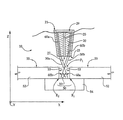
図1を参照すると、本開示による溶接トーチ10が示されている。溶接トーチ10は、溶接ワイヤ供給部12と、それに取り付けられたノズル端部本体20とを有するノズル11を含み、ノズル端部本体20はワイヤ供給側21と溶接側23とを有する。溶接トーチ10は、本明細書で説明するように、二重ワイヤ溶接トーチを備え、これによって、第1および第2の溶接ワイヤをノズル端部本体20から所望の方向に配向することが可能になる。溶接ワイヤは、従来のワイヤスプール等(図示せず)からトーチ10の溶接ワイヤ収容部40aと40b内に供給して、溶接ワイヤ供給部12を通し、ノズル端部本体20の中に入れて、第1および第2の溶接ワイヤガイド30aと30bから出すことが可能である。第1および第2の溶接ワイヤガイド30aと30bのそれぞれは、ノズル端部本体20に結合されている基端31と、その反対側の末端33とを有し得る。さらに、本明細書で説明するように、対象となる溶接ワイヤを同一平面にない逸脱する溶接ワイヤ方向に互いに配向して、いくつかの種類の溶接を容易にすべく、ワイヤガイド30aと30bを構成することが可能である。
Referring to FIG. 1, a
次に、溶接トーチ10の一部の部分断面正面図が示されている図2を参照すると、ノズル端部本体20は、それが部分12のような溶接トーチのワイヤ供給部に結合されることを許容するように構成されるワイヤ供給側21に配置された開口部29を含み得る。他の実施形態では、ノズル端部本体20は、溶接トーチの異なる構成部材に、および/または開口部29とは異なる手段を介して結合することが可能である。ノズル端部本体20はまた、当業者に周知のシールド用のシールドガスをノズル端部本体20の溶接側23から外側に導くように構成されるガス出口27を有する内部ガス通路25を含み得る。いくつかの実施形態では、ノズル端部本体20は、存在する二重ワイヤ溶接トーチのための改良アタッチメントを備えることが可能であり、開口部29により、二重ワイヤ溶接トーチに結合することが容易になる。また、トーチ10のような溶接トーチに結合された場合にガス供給ライン(図示せず)に位置合わせするように、ガス通路25を構成することが可能である。さらに別の実施形態では、ノズル端部本体20は、従来の二重ワイヤ溶接トーチ用の改良部ではなく、狭い溝用の突合せ継手の溶接のようないくつかの種類の溶接にトーチ10を適用可能にするために使用されるアタッチメントを備え得る。このような実施形態では、ノズル端部20がトーチ10に取り付けられていない場合、他の種類の溶接で使用するようにまたは突合せ継手以外の継手を溶接するように、トーチ10を構成することが可能である。いくつかの実施形態では、ノズル端部本体20および溶接ワイヤガイド30aと30bを構成する際に非導電性材料を利用することが望ましいかもしれない。このために、例えば、ノズル端部本体20およびワイヤガイド30aと30bを非導電性セラミック材料から構成してもよい。
Referring now to FIG. 2 where a partial cross-sectional front view of a portion of the
以下の説明から明らかなように、溶接ワイヤガイド30aと30bを介して、例えばワイヤ供給部12によって定められた同一平面の集中する方向から、同一平面にない逸脱する方向に、第1および第2の溶接ワイヤ60aと60bを再配向するように、ノズル端部本体20とその個々の構成部材を構成し得ることが考えられる。このようにして、ワイヤ60aと60bを配向するために磁界またはある他の手段に依存することなく、トーチ10は、所望に応じてガイド30aと30bを介してワイヤを配向できる。本明細書で説明するように、「同一平面にない」という用語は、典型的に、従来の二重ワイヤ溶接トーチの場合と同様に、溶接ワイヤ60aと60bの、および溶接ワイヤガイド30aと30bの方向が、完全には共通面に存在しないことを意味することを理解されたい。
As will be apparent from the following description, the first and second directions are changed from the direction in which the same plane defined by, for example, the
溶接ワイヤ60aと60bの方向について「逸脱する」という用語は、溶接ワイヤ60aと60bが、一般にノズル端部20から互いに離れる方向に延びることを意味することを理解されたい。言い換えれば、ワイヤ60aと60bが離れる距離は、図4aに示されているように、それらのワイヤの先端61において最大になる。それにもかかわらず、本明細書に用いられる際に、「逸脱する」という用語は、互いに接近している個々のライン部の任意の部分は別として、溶接ワイヤ60aと60bによって定められたライン部が、ワイヤ60aと60bの先端61に向かう方向に実際にはより遠くに離れている限り、溶接ワイヤの長さの一部に沿って互いに接近する溶接ワイヤを有する構造を排除するとは理解すべきでない。言い換えれば、ここでは、溶接ワイヤが、それらの先端に向かう方向において、最初はほぼ互いに対向するが、最終的には逸脱して延び得る構造が考えられる。本明細書で説明するように、上記の同一平面にない逸脱する関係により、溶接中のワイヤ60aと60bの所望の位置決めおよび操作が容易になる。ワイヤサイズを用途に応じて変更することが可能であるが、適切な溶接ワイヤの直径は、例えば、約0.045インチであり得る。
It should be understood that the term “depart” with respect to the direction of the
図2には、隣接するワークピース部材52の間の突合せ継手50のような継手に近接して位置決めされたトーチ10が示されている。それぞれのワークピース部材52は、対面しかつ溝59を部分的に画成する縁面53、例えば、平坦な縁面を含むことが可能である。バッキングプレート54は、溝59の片側にわたって配置することが可能であり、また溝59の片側を画成する平坦な部材を備えることが可能である。ワークピース部材52に対するバッキングプレート54の厚さは、ワークピース部材52の厚さよりも比較的薄いかあるいはその厚さよりも厚いこともあり、いくつかの実施形態によって異なり得る。頂面P1は、対面する縁面53およびバッキングプレート54と共に、溝59を画成することが可能である。頂面P1は、それぞれのワークピース部材52の縁面53と頂面55との交点によって定められたラインを含む仮想面を含む。
FIG. 2 shows the
溝59が平行の壁溝に関連して示されているが、本開示はこのことに限定されない。本開示の1つの利点は、縁面53を最初に傾斜させるかさもなければ修正することなく、溶接ワイヤ60aと60bが、継手55内で適切に位置決めされて操作されることを許容するように、トーチ10が、隣接するワークピース部材52の間の突合せ継手のような受け入れ可能なまたはより優れた継手を溶接する能力を有することである。特に、溶接ワイヤ60aと60bは、典型的に、溝59の前後にまた端から端まで互いに逸脱するので、溶接ワイヤ60aと60bの個々のアークが互いに干渉することなくまたワイヤ60aと60bが過度に動き回ることなく、溶接ワイヤ60aと60bに対する磁気的および機械的な力によって、溶接に最適な位置に溶接ワイヤ60aと60bを位置決めできる。しかし、トーチ10は、平行の壁溝内で、さらには溝内で使用される必要が全くなく、その上、トーチ10は、他の形式の継手を溶接する場合に適切に考慮され、従来の溶接トーチよりも優れていることを理解されたい。さらに、上記のように、ノズル端部本体20を、いくつかの継手の溶接を容易にするための付属品として使用し、また他の継手を溶接するために取り外すことが可能である。
Although the
図2に示されている突合せ継手50の内容に戻ると、第1および第2のワイヤガイド30aと30bによって、第1および第2の溶接ワイヤ60aと60bを第1および第2の溶接ワイヤ方向にそれぞれ位置決めし得る。本明細書でさらに説明するように、第1および第2の溶接ワイヤ60aと60bの所定の位置決めにより、溶接ワイヤ60aと60bが第1の継手根元部R1と第2の継手根元部R2とをそれぞれ溶接できるように、溶接ワイヤ60aと60bが配向される。図2aは、根元部R1とR2が溶接された継手50の断面図を示している。溶接溶加材が、溝59を実質的に埋めることが可能であり、またバッキングプレート54およびワークピース部材52の溶融によって、比較的均一な充填融着根元部R1とR2を設けることに留意されたい。従来の多くの溶接方法では、図2aで完全に融着されたものとして示されている領域に不均一性および隙間が生じる。このような不均一性、隙間等は、溶接された継手の伝達で亀裂が入る弱点となる可能性があり、最終的には、構造破壊に至るかまたは少なくとも修理作業が必要となる。ワイヤガイド30aと30bの方向と、その結果として得られたワイヤ60aと60bの方向とにより、個々のワイヤの先端61が、以前の構造では溶接が不可能であったかまたは少なくとも実施できなかった傾斜していない継手の継手根元部に達することが許容される。いくつかの実施形態では、先端61は、根元部R1とR2の約15ミリメートル以内に、さらに他の実施形態では、根元部R1とR2の約10ミリメートル以内に位置決めすることが可能である。継手50は、約35ミリメートルの直径よりも小さくてもよく、いくつかの実施形態では、約20ミリメートルの直径よりも小さくてもよい。
Returning to the contents of the butt joint 50 shown in FIG. 2, the first and second wire guides 30a and 30b move the first and
図2には、X軸、Y軸およびZ軸による3つの空間寸法も示されている。図2に示されているY軸は、トーチ10が溶接中に移動されるほぼ平行方向に配向されるが、本開示はこのことに限定されない。図2のトーチ10の正面図は、第1および第2のワイヤ60aと60bの方向によって定められた突出角θ1を示しており、この突出角は、Z軸およびX軸のそれぞれに交差しかつY軸に対して直角である面に位置する。言い換えれば、ワイヤ60aと60bの配向部が、X軸とZ軸とに交差する面に突出された場合、突出部が、いくつかの実施形態では、約6.0°、例えば、約6.4°の角度で互いに位置決めされていると理解することが可能である。他の実施形態では、角度θ1は、約4.0°〜約11.0°の範囲にあることが可能であり、さらに、約6.0°〜約9.0°の範囲にあるかまたは他の範囲内にあることが可能である。溶接ワイヤ60aと60bの間の所望の角度関係を提供するために、ワイヤガイド30aと30bも、同一平面にない逸脱する関係で配向される。
FIG. 2 also shows three spatial dimensions by the X axis, the Y axis, and the Z axis. The Y axis shown in FIG. 2 is oriented in a generally parallel direction in which the
複数の要因に基づいて、角度θ1を選択し得ることを理解されたい。ワイヤ60aと60bが比較的小さな角度θ1に位置決めされた場合、ワイヤ60aと60bは、それと平行関係にある縁面53に比較的近接して配向することが可能である。したがって、ワイヤ60aと60bに関連する電気アークが、根元部R1とR2ではなく、縁面53に延びる傾向が大きくなり得る。一般に、個々の電気アークが、根元部R1とR2ではなく、縁面53を溶接し、したがって、ワイヤ60aと60bの間のある角度により、根元部R1とR2が、適切に配向された電気アークによって正確に融着されることが保証されることが望ましいので、個々の電気アークが継手50の壁部に接触することは望ましくない。さらに、ワイヤ60aと60bの角度は、互いに平行であるのとは対照的に、溶接工程から生じるスパッタの排出を容易にすることが望ましくなるようにされる。
It should be understood that the angle θ1 can be selected based on multiple factors. When the
また、ワイヤ60aと60bの分離により、ワイヤ60aと60bの位置決め、したがって溶接工程全体に関する制御の損失を生じさせることがあるアークとワイヤとの間の磁気的に誘導される干渉が回避される。さらに、継手形状、ワイヤ長さおよびトーチサイズは、角度θ1の大きさにいくらかの影響を与えている可能性があるが、比較的太い継手に関しては、溶融プールのサイズまたは均一性が妥協される箇所まで、θ1は比較的大きくなる可能性があり、二重ワイヤ溶接が実施できなくなることが考えられる。当業者は、溶融プールのサイズおよび均一性に関連する制限を容易に認識するであろう。今説明したθ1の範囲は、種々の継手を溶接するために適切に考慮される上記の要因の場合に妥協されるが、本開示はこのことに限定されない。角度θ1は、上記のワイヤ60aと60bの「端から端までの」逸脱に対応する。
Also, the separation of the
図3を参照すると、ほぼX軸に沿って位置合わせされた方向から見たトーチ10の一部が示されている。図3は、ワイヤガイド30aと30bによって定められたワイヤ60aと60bの個々の溶接ワイヤ方向の間の第2の突出角θ2を示している。いくつかの実施形態では、例えば、Z軸とY軸とに交差する面に突出されたワイヤ60aと60bの方向によって定められた第2の突出角θ2は約9.0°であり得る。他の実施形態では、θ2は、約4.0°〜11.0°の範囲にあることが可能であり、さらに、約6.0°〜約9.0°の範囲または他の範囲にあることが可能である。第2の突出角θ2は、上記のワイヤ60aと60bの「前後の」逸脱に対応する。
Referring to FIG. 3, a portion of the
また、複数の要因に基づいて、第2の突出角θ2を決定し得る。角度θ1について説明したようなワイヤ60aと60bのある角度は、スパッタを排出することを許容するのに役立つような望ましいものかもしれないが、この点に関して、θ2は、一般に、必ずしも、より重要な角度であるとは限らない。さらに、溶接中に形成される溶融プールのサイズは、選択された角度θ2に基づいている場合がある。溶融プールが大きすぎる場合、溶接アークからの熱をより拡散させる可能性があり、この結果、ワークピースへの熱の総量が大きくなって、根元部R1とR2を正確に融着するのに必要なエネルギーもそれだけ大きくなるので、最適な効率よりも低い効率で、溶接工程が行われることがある。他の問題は、個々のアークの間の溶融プールに生じる可能性がある「リップル」に関するものである。このリップルは、より大きな角度θ2で生じる傾向があるので、アークが大きくなるにつれて、さらに拡散されることが多くなる。したがって、対象となる継手内のプールのサイズまたは長さ、およびアークの一方の遮蔽を生じさせることがある過大なリップルサイズは、比較的大きな角度θ2に関連するような問題を表している。しかし、横方向角度θ1と同様に、磁気干渉の問題の故に、ワイヤ60aと60bを互いに密接に位置決めすべきでない。このようにして、開示されている角度θ2の範囲は、種々の問題にも対処している。
Further, the second protrusion angle θ2 can be determined based on a plurality of factors. While certain angles of the
以前の溶接方法は、少なくとも部分的に上記の問題があったために、継手構成部材を最初に修正しなければ、継手に対して溶接ワイヤを正確に位置決めして配向し、ワイヤの操作を容易にすることができなかった。このようにして、本発明で開示されている方法および装置は、認識されているがこれまで未解決である関連技術の問題に対処する。ワイヤ60aと60bの端から端までの逸脱と共に、ワイヤ60aと60bの前後の逸脱により、ステーバ(Stava)への(特許文献1)のような上記の以前の構造では教示または認識されなかった三次元空間におけるワイヤの最適な位置決めが許容される。本明細書で説明されているようなワイヤ60aと60bの位置決めにより、溶融プールのサイズを最適にすること、ワイヤおよび/またはアークの間の磁気的に誘導される干渉の危険性を最小にすること、および根元部R1とR2に対してワイヤ60aと60bの意図した位置から逸脱する個々のアークの危険性を最小にすることが可能になる。これらの有利な特性により、継手の個々の構成部材を最初に修正することなく、また脆性のおよび/または扱いにくい溶接トーチを使用することなく、本発明で開示されている構造によって突合せ継手50のような比較的細い継手の溶接がすべて可能になる。
Previous welding methods suffered at least in part from the above problems so that if the fitting components are not first modified, the welding wire is accurately positioned and oriented with respect to the fitting to facilitate wire manipulation. I couldn't. In this way, the methods and apparatus disclosed in the present invention address the problems of the related art that are recognized but not yet solved. Tertiary that was not taught or recognized in the previous structure as described above (US Pat. No. 6,077,049) to Stava, due to the end-to-end departure of
図示されている突出角θ1とθ2を考慮すると、ワイヤ60aと60bは、本明細書でさらに説明しかつ本図でさらに示すように、溶接方向に前後に逸脱して互いに離れるように角度付けされており、また溶接方向に対して横方向に端から端まで逸脱して互いに離れるように角度付けされていると理解することも可能である。ワイヤ60aと60bの方向は、少なくとも部分的にワイヤガイド30aと30bの方向によって定められる。次に、図4aを参照すると、ワイヤガイド30aと30bからそれぞれ延びる溶接ワイヤ60aと60bを有するノズル端部本体20の端面図が示されている。ワイヤガイド30aと30bは、図4aの端から端まで示されている溶接進行面Wを画成する。溶接進行面Wは、トーチ10の位置決めに応じて、溝59の中央に沿ってほぼ長手方向に延び、また突合せ継手50に関連する縁面53に平行して配向される。
Considering the illustrated protrusion angles θ1 and θ2, the
ワイヤガイド30aと30bは、他の面Tも画成し、この他の面Tは、溶接進行面Wに対して横方向にあり、それに対して垂直であり、ワイヤガイド30aと30bの基端31に交差することが可能である。図4aに示したように、それぞれの面TとWは、ノズル端部本体20の端面39に対して垂直に配向されると考えることが可能である。ワイヤガイド30aと30bは、さらに他の面P2も画成し、図3の端から端まで示されているこの面P2は、末端33に交差し、また例えば互いに垂直に配向される面TとWに対して横方向に配向される。
The wire guides 30a and 30b also define another surface T, which is transverse to and perpendicular to the welding progress surface W and is proximal to the wire guides 30a and 30b. It is possible to cross at 31. As shown in FIG. 4 a, each surface T and W can be considered to be oriented perpendicular to the end surface 39 of the
したがって、例示した実施形態では、第1の突出角θ1は横方向面Tに位置し、これに対して、第2の突出角θ2は溶接進行面Wに位置する。ワイヤガイド30aと30bの方向は、ワイヤガイド30aと30bのそれぞれが、約2.0°〜約6.0°の横方向面Tに対する、および約2.0°〜約6.0°の溶接進行面Wに対する角度を定めるような方向であり得る。示されている角度は例示的なものに過ぎず、また本開示の完全で適正な範囲の溶接トーチ構造を除外することなく、種々の面の相対位置決め、示されている角度の大きさ等を変更するであろう開示されているトーチ10の構造の変更をなし得ることを理解されたい。
Therefore, in the illustrated embodiment, the first protrusion angle θ1 is located on the lateral surface T, while the second protrusion angle θ2 is located on the welding progress surface W. The direction of the wire guides 30a and 30b is such that each of the wire guides 30a and 30b is welded to a lateral surface T of about 2.0 ° to about 6.0 ° and about 2.0 ° to about 6.0 °. The direction may determine the angle with respect to the traveling surface W. The angles shown are only exemplary and the relative positioning of the various surfaces, the magnitude of the angles shown, etc., without excluding the complete and proper range of welding torch structures of the present disclosure. It should be understood that changes to the structure of the disclosed
ワイヤガイド30aと30bが面Tから異なる方向に逸脱すること、および溶接ワイヤ60aと60bも、面Tから、ワイヤガイド30aと30bの方向に対応する個々の異なる方向に逸脱することに留意されたい。さらに、それぞれのワイヤガイド30aと30bが、溶接進行面Wに向かって角度付けされる少なくとも一部を含むことに留意されたい。ワイヤガイド30aと30bの相対長さおよび相対位置決めに応じて、溶接進行面Wに交差することなくそれに向かって、ワイヤガイド30aと30bのそれぞれの全体を角度付けすることが可能である。さらに、ワイヤガイド30aと30bを平行に配向することも可能であるが、そのことは必要でない。他の実施形態では、ワイヤガイド30aと30bは、非平行であることが可能であるか、または溶接進行面Wに交差し、したがって、溶接進行面Wに向かって角度付けされた部分と、溶接進行面Wから離れるように角度付けされた他の部分とを含むことが可能である。なおさらに、溶接進行面Wおよび横方向面Tが例示目的のために本明細書に記載されており、また本開示の範囲から逸脱することなく、面Wではなく面Tに位置合わせされた方向、またはさらに他の方向に、トーチ10を移動させ得ることを理解されたい。
Note that the wire guides 30a and 30b deviate from the surface T in different directions, and that the
いくつかの実施形態では、溶接ワイヤ60aと60bの先端61は、溶接進行面Wから等距離に位置決めすることが可能であり、また横方向面Tからも等距離に位置決めすることが可能である。さらに、ワイヤガイド30aと30bの末端33は、面TとWの一方または両方から等距離に位置決めすることが可能である。基端31は、面Wから等距離に位置決めすることが可能である。しかし、本開示はこのことに限定されず、ここで、ワイヤガイド30aと30bは、異なる長さまたは相対方向を有し、面TとWは、記載されている種々の特徴により、等距離に位置決めされないかもしれない。上記のように、溶接ワイヤガイド30aと30bが溶接進行面Tに向かって角度付けされるべく、溶接ワイヤガイド30aと30bを配向し得る。さらに、ワイヤ60aと60bの間の最も近接する箇所が、ワイヤガイド30aと30bの基端31と、ワイヤ60aと60bの先端61との間の位置に存在するように、溶接ワイヤ60aと60bを配向すべく、溶接ワイヤガイド30aと30bを構成し得る。ワイヤガイド30aと30bの間の最も近接する箇所が、基端31に、末端33に、または基端31と末端33との間のワイヤガイド30aと30bの位置に存在するように、溶接ワイヤガイド30aと30bを非同一平面に逸脱して配向することが可能である。
In some embodiments, the
図4bを参照すると、本開示によるノズル端部本体120の代替実施形態が示されている。ノズル端部本体120は、図1〜図4aのノズル端部本体20と同様に、溶接進行面W’と横方向面T’とを画成する第1および第2の溶接ワイヤガイド130aと130bを含む。しかし、ノズル端部本体120は、ワイヤガイド130aと130bが、ノズル端部本体20のような時計回りではなく、ほぼ反時計回りにノズル端部本体120から延びるという点において、例示されている他の実施形態とは異なる。図4bに示されているノズル端部本体120の視点から、左側のワイヤガイド130aはノズル本体端面139から下向きおよび右方向に延び、これに対して、右側のワイヤガイドは端面139から上向きおよび左方向に延びる。この構成が、ノズル端部本体20の逆であることに留意されたい。
Referring to FIG. 4b, an alternative embodiment of the
代替実施形態では、溶接ワイヤガイド30a、30bおよび130a、130bのそれぞれは、本開示の範囲から逸脱することなく、図4aと図4bの溶接ワイヤガイドの例示されている構成のそれぞれから、約180°で再配向することが可能である。このような実施形態では、個々のワイヤガイド30a、30bおよび130a、130bのすべては、面W、TおよびW’、T’のそれぞれから逸脱し、また個々のワイヤガイドの基端において個々のワイヤガイドの最も近接する箇所を有するであろう。しかし、個々のワイヤガイド30a、30bおよび130a、130bが、面W、TおよびW’、T’のそれぞれの一方に向かって配向された少なくとも一部を含む実施形態が、実用的な実施方法を表していることが考えられる。 In an alternative embodiment, each of the welding wire guides 30a, 30b and 130a, 130b is approximately 180 from each of the illustrated configurations of the welding wire guides of FIGS. 4a and 4b without departing from the scope of the present disclosure. Reorientation at ° is possible. In such an embodiment, all of the individual wire guides 30a, 30b and 130a, 130b deviate from each of the surfaces W, T and W ′, T ′ and the individual wires at the proximal end of the individual wire guides. Will have the closest point of the guide. However, an embodiment in which the individual wire guides 30a, 30b and 130a, 130b include at least a portion oriented towards one of the surfaces W, T and W ′, T ′ is a practical method of implementation. It is possible to represent.
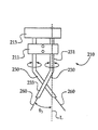
図5を参照すると、溶接ワイヤガイド230を有する溶接トーチ210の一部が示されており、溶接ワイヤガイド230の少なくとも一方は、同一平面にない逸脱する異なる複数の関係で溶接ワイヤ260を配向するように調整可能である。ワイヤガイド230の一方または両方は、個々のワイヤガイド230の基部231を通過するラインLを中心として、対応する溶接ワイヤ260を無数の角度方向に位置決めするように、溶接トーチ主体213に対して回転可能であり得る。ワイヤガイド230の一方または両方は、基部231に対してある角度で位置決めされた末端部233を含むことが可能である。したがって、個々のワイヤガイド230を回転させることにより、ラインLに対してある角度で、例えば、約20°の角度θ3で配向された側面を有する円錐を定める経路を中心として、対応する溶接ワイヤ260を移動させることができる。ワイヤガイド230を所望の方向に固定するために、クランプ211を設けることが可能である。他の実施形態では、ワイヤガイド230の一方または両方は、ボール・コーンジョイントのようなある他の手段を介して調整可能であり得るが、所望の場合、考えられるすべての実施形態は、同一平面にない逸脱する関係で、または同一平面にない逸脱する異なる複数の関係で、溶接ワイヤ260を配向し得るように構成される。さらに、いくつかの種類の溶接のために所望の場合には、同一平面にあるおよび/または集中する関係でワイヤ260を位置決めするように、しかし、他の種類の溶接のために所望の場合には、同一平面にあるおよび/または集中する関係からワイヤ260を調整可能であるように、ワイヤガイド230が構成される実施形態が考えられる。
Referring to FIG. 5, a portion of a
継手形状および寸法が溶接ワイヤの最適な位置決めに影響を与え、したがって、特定の継手または溶接の種類に最適なワイヤ方向を決定することを許容するように、ワイヤ260をトーチ210の種々の方向に位置決めし得ることを理解されたい。トーチ210が、このような調査目的に十分に適していることが考えられるが、トーチ210は、このことに限定されず、製造環境に使用してもよい。
The joint shape and dimensions affect the optimal positioning of the welding wire, and thus the
図1〜図4aを参照すると、ワークピース部材52を接合する溶接操作の前に、対面する縁面53を位置合わせすることによって、またバッキングプレート54が溝59にわたって延びるようにバッキングプレート54を適切に位置決めすることによって、溝59を作ることが可能である。例えば、複数のスポット溶接によって、バッキングプレート54を所定位置に一時的に固定してもよい。次に、溶接ワイヤ60aと60bの先端61が、溝59内に存在する状態で根元部R1とR2に向かって配向されるように、トーチ10を位置決めし得る。その次に、電気アークが先端61から延びて根元部R1とR2の溶接を開始するように、電気エネルギーをそれぞれのワイヤ60aと60bに供給し、トーチ10を継手50に沿って、溶接進行面Wに位置合わせされた方向に移動させて、根元部R1とR2を同時に溶接することが可能である。トーチ10は、用途に応じて、毎分約40センチメートル〜毎分約90センチメートル、例えば、毎分約50センチメートルの移動速度で、ロボット(図示せず)により継手50に沿って移動させ得る。他の実施形態では、トーチ10は、異なる速度で移動させることが可能であり、またロボットを使用するのではなく、手動で移動および制御することが可能である。例えば、ワイヤ60aと60bへの同期信号を有するコンピュータ制御されたパルス波形によって、電気エネルギーを溶接ワイヤ60aと60bに供給してもよい。約15%〜約20%の範囲にある、潜在的には最高約30%のアーク矯正は、溶接中に実行することが可能である。ミシガン州(Michigan)、ブライトン(Brighton)のフロニウスUSA社(Fronius USA)は、本開示に関連して使用するための複数の溶接制御装置の内の市販の適切な1つの溶接制御装置を提供している。
1-4a, prior to the welding operation to join the
溶接中に、溶接業者に周知の方法で、ガス通路25を介してシールドガスを供給し得る。ワイヤ60aと60b、およびそれらの先にある先端61と共に、トーチ10を継手50に比較的近接して位置決めすることを許容することによって、本開示により、いくつかの実施形態で、従来の方法に比べて比較的少量のガスおよび/または少量の電気エネルギーで済ませられるように、シールドガスを継手50にさらに有効に導くことが許容される。さらに、傾斜継手に比べて、継手50はより制限された形状であるので、シールドガスは比較的有効であるかもしれず、いくつかの実施形態では、シールドガスの使用が、少なくとも約30%まで低減される。ノズル端部本体20およびワイヤガイド30aと30bを通して、ワイヤ60aと60bを供給し、溶接工程でワイヤ60aと60bが消費されるときに、溝50内において、根元部R1とR2に対して先端61を所望の位置に維持することが可能である。適切なワイヤ供給速度は、毎分約8メートル+/−毎分約3メートルであり得る。
During welding, shielding gas may be supplied through the
図4bのノズル端部本体120を利用するトーチの操作は、トーチ10について説明されている操作と同様に行うことが可能である。図5のトーチ210に関して、継手50のような継手の溶接は、トーチ10について説明されている溶接と同様のものであり得るが、この場合、溶接ワイヤガイド230は、溶接を開始する前に、選択された方向に固定されている。
The operation of the torch using the
本開示は、以前の多数のシステムよりも高い継手の完成率、および以前の多数のシステムよりも信頼性の高い継手が実現可能である溶接方法および溶接装置を提供する。トーチ10、および本明細書で考慮されている他の溶接トーチは、以前の構造で可能であったよりも広い溶接ワイヤの適用範囲と、以前の構造で可能であったよりも高い操作性とを提供し、これにより、電気アークを適切に配向して、根元部R1とR2の融着をより良く保証することが許容される。また、最初に継手を特に準備することなく、溶接ワイヤを根元部に到達させることを許容するように、予備製造処理が以前に必要であった太い突合せ継手構成部材を比較的迅速かつ確実に溶接することが可能であり、これにより、製造時間が低減されまた廃棄材料が低減される。
The present disclosure provides a welding method and apparatus that can achieve a higher joint completion rate than a number of previous systems and a more reliable joint than a number of previous systems. The
以前のいくつかのシステムにおいて、平行でない二重溶接ワイヤがいくつかの利点を有することができることが認識されていたが、本明細書で説明されているように継手根元部への到達を改良すべく、同一平面にない逸脱する関係で溶接ワイヤが配向される方法は、溶接技術ではこれまで未知であった。本開示により、より強固な構造が提供され、また溶接ワイヤまたは溶接トーチの他の構成部材の比較的複雑な振動に対して、信頼性の高い継手を実現することが求められていた高価な脆性の機器に依存する以前の方法も改良される。なおさらに、ワイヤ60aと60bが溝59に沿って通過されるときに、ワイヤ60aと60bが継手50に対して同一方向に維持されるので、継手の断面を介した熱入力はより均一になり、この結果、溶接の熱歪みが低減される。
In some previous systems, it was recognized that a non-parallel double welding wire could have several advantages, but improved access to the joint root as described herein Thus, the method by which the welding wire is oriented in a deviating relationship that is not in the same plane has been unknown to the welding technology. The present disclosure provides a more robust structure and expensive brittleness that was required to provide a reliable joint against the relatively complex vibrations of welding wire or other components of the welding torch. Previous methods that depend on the equipment are also improved. Still further, when the
本発明の説明は、例示目的に過ぎず、本開示の範囲を限定すると決して解釈すべきではない。したがって、当業者は、本開示の意図した精神と範囲から逸脱することなく、本発明で開示されている実施形態のために種々の修正をなし得ることを理解するであろう。例えば、本発明の説明は、消費できる二重ワイヤトーチを大部分中心にしてなされてきたが、他の実施形態において、消費できない溶接ワイヤを使用してもよい。同様に、追加の充填材料を、溶接中に供給するか、または溶接前に、溶接すべき継手に位置決めすることが可能である。他の形態、特徴および利点は、添付図面および添付された特許請求の範囲を考慮すれば明らかになるであろう。 The description of the present invention is for illustrative purposes only and should in no way be construed as limiting the scope of the present disclosure. Accordingly, one of ordinary skill in the art appreciates that various modifications can be made to the embodiments disclosed in the present invention without departing from the intended spirit and scope of the disclosure. For example, although the description of the present invention has been largely centered on a consumable double wire torch, in other embodiments, non-consumable welding wires may be used. Similarly, additional filler material can be supplied during welding or positioned at the joint to be welded prior to welding. Other forms, features and advantages will become apparent when considering the appended drawings and appended claims.
10 溶接トーチ
11 ノズル
12 溶接ワイヤ供給部
20 ノズル端部本体
21 溶接ワイヤ供給側
23 溶接側
25 ガス通路
27 ガス出口
29 開口部
30a 第1の溶接ワイヤガイド
30b 第2の溶接ワイヤガイド
31 基端
33 末端
39 ノズル端部本体の端面
40a 溶接ワイヤ収容部
40b 溶接ワイヤ収容部
50 継手
52 ワークピース部材
53 縁面
54 バッキングプレート
55 頂面
59 溝
60a 第1の溶接ワイヤ
60b 第2の溶接ワイヤ
61 溶接ワイヤの先端
120 ノズル端部本体
130a 溶接ワイヤガイド
130b 溶接ワイヤガイド
139 ノズル端部本体の端面
210 溶接トーチ
211 クランプ
213 主体部分
230 溶接ワイヤガイド
231 基部
233 末端部
260 溶接ワイヤ
L ライン
P1 面
P2 面
R1 継手根元部
R2 継手根元部
W 溶接進行面
W’ 溶接進行面
T 横方向面
T’ 横方向面
DESCRIPTION OF
Claims (20)
溶接すべきワークピース継手に対して溶接トーチを溶接方向に移動させるステップと、
溶接トーチの移動中に、溶接トーチのノズル端部本体に結合された基端と、末端と、を有する第1の溶接ワイヤガイドを通して第1の溶接ワイヤを供給し、溶接トーチのノズル端部本体に結合された基端と、末端と、を有する第2の溶接ワイヤガイドを通して第2の溶接ワイヤを供給するステップであって、第1の溶接ワイヤガイドは第1の溶接ワイヤ方向を定め、第2の溶接ワイヤガイドは、第1の溶接ワイヤ方向に対して同一平面にない逸脱する第2の溶接ワイヤ方向を定める、ステップと、
を含み、
第1の溶接ワイヤの供給および第2の溶接ワイヤの供給は、それぞれ、各溶接ワイヤを対応する溶接ワイヤガイドを通して、溶接トーチのノズル端部本体から、少なくとも溶接進行面と第2の面との内の少なくとも一方に向かう供給を含み、溶接進行面は、溶接方向に合わせられて、第1の溶接ワイヤガイドの基端と第2の溶接ワイヤガイドの基端との間に位置するノズル端部本体上の点と交差し、第2の面は、溶接進行面と垂直であって、第1の溶接ワイヤガイドの基端と第2の溶接ワイヤガイドの基端との間に位置するノズル端部本体上の点と交差する溶接方法。 A welding method,
Moving the welding torch in the welding direction relative to the workpiece joint to be welded;
During movement of the welding torch, a first welding wire is fed through a first welding wire guide having a proximal end coupled to the nozzle end body of the welding torch and a distal end, the nozzle end body of the welding torch Supplying a second welding wire through a second welding wire guide having a proximal end coupled to the distal end and a distal end, the first welding wire guide defining a first welding wire direction, The two welding wire guides define a deviating second welding wire direction that is not coplanar with respect to the first welding wire direction;
Including
The supply of the first welding wire and the supply of the second welding wire are respectively performed by passing each welding wire through the corresponding welding wire guide from the nozzle end body of the welding torch at least between the welding progress surface and the second surface. A nozzle end including a supply directed to at least one of the first and the welding progress surface is aligned with the welding direction and located between the proximal end of the first welding wire guide and the proximal end of the second welding wire guide A nozzle end that intersects a point on the body and the second surface is perpendicular to the welding progress surface and is located between the proximal end of the first welding wire guide and the proximal end of the second welding wire guide A welding method that intersects points on the body.
ノズル端部本体と、
ノズル端部本体に結合されかつある方向を有する第1の溶接ワイヤガイドと、
ノズル端部本体に結合され、かつ第1の溶接ワイヤガイドの方向とは異なる方向を有する第2の溶接ワイヤガイドと、
を備え、
第1および第2の溶接ワイヤガイドのそれぞれは、ノズル端部本体に結合されている基端と、末端とを含み、第1および第2の溶接ワイヤガイドは、第1および第2の溶接ワイヤガイドの末端に交差する第1の面と、基端のそれぞれに交差しかつ第1の面に対して横方向に配向された第2の面と、第1の面に垂直でありかつ第2の面に垂直な第3の面と、をさらに画成し、第2および第3の面のそれぞれは、第1および第2の溶接ガイドガイドの基端の間に位置するノズル端部本体上の点と交差し、第1および第2の溶接ワイヤガイドの方向は第2の面とは異なる方向に逸脱し、それぞれの溶接ワイヤガイドは、ノズル端部本体から離れて第3の面に向かうように角度付けされた部分をさらに含むノズル端部。 A nozzle end for a welding torch assembly,
The nozzle end body,
A first welding wire guide coupled to the nozzle end body and having a direction;
A second welding wire guide coupled to the nozzle end body and having a direction different from the direction of the first welding wire guide;
With
Each of the first and second welding wire guides includes a proximal end coupled to the nozzle end body and a distal end, and the first and second welding wire guides are the first and second welding wires. A first surface intersecting the distal end of the guide; a second surface intersecting each of the proximal ends and oriented transversely to the first surface; and a second surface perpendicular to the first surface and second A third surface perpendicular to the first surface, each of the second and third surfaces being on a nozzle end body located between the proximal ends of the first and second welding guide guides. And the directions of the first and second welding wire guides deviate in a direction different from the second surface, and each welding wire guide is away from the nozzle end body and toward the third surface. A nozzle end further including an angled portion.
第1の溶接ワイヤ方向に第1の溶接ワイヤを配向するように構成された第1の溶接ワイヤガイドと、第1の溶接ワイヤ方向に対して同一平面にない逸脱する第2の溶接ワイヤ方向に、第2の溶接ワイヤを配向するように構成された第2の溶接ワイヤガイドと、を有するノズル端部本体を含むノズルを備え、第1および第2の溶接ワイヤガイドのそれぞれは、ノズル端部本体に結合される基端と、末端とを含み、
第1および第2の溶接ワイヤガイドは、それらの末端に交差する第1の面と、それらの基端の交差しかつ第1の面に対して横方向に配向された第2の面と、第1の面に対して直角かつ第2の面に対して直角である第3の面と、をさらに画成し、第2および第3の面のそれぞれは、第1および第2の溶接ガイドガイドの基端の間に位置するノズル端部本体上の点と交差し、第1および第2の溶接ワイヤガイドの方向は第2の面とは異なる方向に逸脱し、それぞれの溶接ワイヤガイドは、ノズル端部本体から離れて第3の面に向かうように角度付けされた部分をさらに含む溶接トーチ。 A welding torch,
A first welding wire guide configured to orient the first welding wire in the first welding wire direction, and a second welding wire direction that is not coplanar with respect to the first welding wire direction; A nozzle including a nozzle end body having a second welding wire guide configured to orient the second welding wire, each of the first and second welding wire guides having a nozzle end A proximal end coupled to the body and a distal end;
The first and second welding wire guides have first surfaces that intersect their distal ends, second surfaces that intersect their proximal ends and are oriented transversely to the first surface; A third surface perpendicular to the first surface and perpendicular to the second surface, wherein each of the second and third surfaces is a first and second welding guide. Intersecting a point on the nozzle end body located between the proximal ends of the guides, the directions of the first and second welding wire guides deviate in a direction different from the second surface, and each welding wire guide is The welding torch further including a portion angled away from the nozzle end body toward the third surface.
第1および第2の溶接ワイヤガイドは、第1および第2の溶接ワイヤガイドの個々の末端に交差する第1の面と、第1の面に対して垂直に配向されかつ基端および溶接進行面に交差する第2の面と、を画成し、溶接進行面は、第1および第2の面のそれぞれに対して垂直に配向され、
第1および第2の溶接ワイヤ方向は、第2の面から逸脱して、溶接進行面内における各溶接ワイヤ方向の間の第1の突出角を約6.0°〜約9.0°の範囲に定め、第2の面内における各溶接ワイヤ方向の間の第2の突出角を約4.0°〜約11.0°の範囲に定める請求項16に記載の溶接トーチ。 Each of the welding wire guides includes a proximal end and a distal end,
The first and second welding wire guides have a first surface intersecting the respective distal ends of the first and second welding wire guides, and are oriented perpendicular to the first surface and proximal and weld progressions A second surface intersecting the surface, the welding progress surface being oriented perpendicular to each of the first and second surfaces;
The first and second welding wire directions deviate from the second surface and have a first protrusion angle between each welding wire direction within the welding progression plane of about 6.0 ° to about 9.0 °. The welding torch according to claim 16, wherein the welding torch is defined as a range and a second projection angle between each welding wire direction in the second plane is defined in a range of about 4.0 ° to about 11.0 °.
Applications Claiming Priority (2)
| Application Number | Priority Date | Filing Date | Title |
|---|---|---|---|
| US11/449,054 US7525067B2 (en) | 2006-06-08 | 2006-06-08 | Dual wire welding torch and method |
| US11/449,054 | 2006-06-08 |
Related Parent Applications (1)
| Application Number | Title | Priority Date | Filing Date |
|---|---|---|---|
| JP2007099496A Division JP2007326148A (en) | 2006-06-08 | 2007-04-05 | Double wire welding torch and method pertinent to it |
Publications (2)
| Publication Number | Publication Date |
|---|---|
| JP2012206175A true JP2012206175A (en) | 2012-10-25 |
| JP5571745B2 JP5571745B2 (en) | 2014-08-13 |
Family
ID=38820853
Family Applications (2)
| Application Number | Title | Priority Date | Filing Date |
|---|---|---|---|
| JP2007099496A Pending JP2007326148A (en) | 2006-06-08 | 2007-04-05 | Double wire welding torch and method pertinent to it |
| JP2012172001A Active JP5571745B2 (en) | 2006-06-08 | 2012-08-02 | Double wire welding torch and related methods |
Family Applications Before (1)
| Application Number | Title | Priority Date | Filing Date |
|---|---|---|---|
| JP2007099496A Pending JP2007326148A (en) | 2006-06-08 | 2007-04-05 | Double wire welding torch and method pertinent to it |
Country Status (2)
| Country | Link |
|---|---|
| US (1) | US7525067B2 (en) |
| JP (2) | JP2007326148A (en) |
Families Citing this family (17)
| Publication number | Priority date | Publication date | Assignee | Title |
|---|---|---|---|---|
| US20080169336A1 (en) * | 2007-01-11 | 2008-07-17 | Spiegel Lyle B | Apparatus and method for deep groove welding |
| US20090277877A1 (en) * | 2008-05-08 | 2009-11-12 | Daniels Craig A | Apparatus and method for welding objects |
| US9555493B2 (en) * | 2008-07-09 | 2017-01-31 | Lincoln Global, Inc. | Apparatus for welding with curtain electrodes and strip electrodes |
| JP2010082624A (en) * | 2008-09-29 | 2010-04-15 | Daihen Corp | Two-wire welding torch, and two-wire welding equipment using the same |
| KR101536804B1 (en) * | 2009-04-01 | 2015-07-14 | 이에스에이비 아베 | Welding head and welding head assembly for an arc-welding system |
| US9839970B2 (en) | 2010-12-21 | 2017-12-12 | Lincoln Global, Inc. | Dual wire welding system and method |
| DE102012202602A1 (en) * | 2012-02-21 | 2013-08-22 | Siemens Aktiengesellschaft | Welding apparatus and method for operating a welding apparatus |
| JP5843683B2 (en) * | 2012-03-28 | 2016-01-13 | 株式会社神戸製鋼所 | Tandem welding torch |
| DE102012020801A1 (en) * | 2012-10-23 | 2014-04-24 | Linde Aktiengesellschaft | Multi-flame burner and method for heating a workpiece |
| JP5979734B2 (en) * | 2014-11-28 | 2016-08-31 | エーエスアーベー アーベー | Welding head and welding head assembly for an arc welding system |
| US10532418B2 (en) | 2017-08-08 | 2020-01-14 | Lincoln Global, Inc. | Dual wire welding or additive manufacturing contact tip and diffuser |
| US11440121B2 (en) | 2017-08-08 | 2022-09-13 | Lincoln Global, Inc. | Dual wire welding or additive manufacturing system and method |
| US11504788B2 (en) | 2017-08-08 | 2022-11-22 | Lincoln Global, Inc. | Dual wire welding or additive manufacturing system and method |
| US10792752B2 (en) | 2017-08-08 | 2020-10-06 | Lincoln Global, Inc. | Dual wire welding or additive manufacturing system and method |
| US10773335B2 (en) | 2017-08-08 | 2020-09-15 | Lincoln Global, Inc. | Dual wire welding or additive manufacturing system and method |
| US11285557B2 (en) | 2019-02-05 | 2022-03-29 | Lincoln Global, Inc. | Dual wire welding or additive manufacturing system |
| US11498146B2 (en) | 2019-09-27 | 2022-11-15 | Lincoln Global, Inc. | Dual wire welding or additive manufacturing system and method |
Citations (5)
| Publication number | Priority date | Publication date | Assignee | Title |
|---|---|---|---|---|
| JPS6246192U (en) * | 1985-09-04 | 1987-03-20 | ||
| JPH03297574A (en) * | 1990-04-17 | 1991-12-27 | Babcock Hitachi Kk | Tig arc welding torch and welding apparatus |
| JPH05237663A (en) * | 1992-03-03 | 1993-09-17 | Babcock Hitachi Kk | Tig welding torch |
| JPH10109174A (en) * | 1996-10-04 | 1998-04-28 | Ishikawajima Harima Heavy Ind Co Ltd | Two-pole type inter-pole variable welding torch nozzle |
| JP2001071132A (en) * | 1999-08-18 | 2001-03-21 | Lincoln Global Inc | Apparatus and method for electric welding |
Family Cites Families (11)
| Publication number | Priority date | Publication date | Assignee | Title |
|---|---|---|---|---|
| JPS5139627B2 (en) * | 1973-02-23 | 1976-10-28 | ||
| JPS55112181A (en) * | 1979-02-23 | 1980-08-29 | Nippon Kokan Kk <Nkk> | Welding method for production of large-diameter thick-walled steel pipe |
| JPH069749Y2 (en) * | 1988-11-24 | 1994-03-16 | 三菱重工業株式会社 | Narrow groove tip welding equipment |
| JP3089060B2 (en) * | 1991-07-03 | 2000-09-18 | 愛知産業株式会社 | Automatic welding equipment |
| US5155330A (en) * | 1991-08-02 | 1992-10-13 | The Lincoln Electric Company | Method and apparatus for GMAW welding |
| JPH07276052A (en) * | 1994-02-18 | 1995-10-24 | Hitachi Zosen Corp | First layer welding method and stacking layer welding method for narrow gap joint |
| JPH08294773A (en) * | 1995-04-26 | 1996-11-12 | Yoshinori Suzuki | Manufacture of reinforced steel welded joint |
| US5714735A (en) * | 1996-06-20 | 1998-02-03 | General Electric Company | Method and apparatus for joining components with multiple filler materials |
| JPH10156532A (en) * | 1996-11-29 | 1998-06-16 | Nkk Corp | Multiple electrode gas shielded metal arc welding method |
| US6683279B1 (en) * | 2001-12-27 | 2004-01-27 | Delford A. Moerke | Twin MIG welding apparatus |
| US7115324B1 (en) * | 2003-08-29 | 2006-10-03 | Alcoa Inc. | Method of combining welding and adhesive bonding for joining metal components |
-
2006
- 2006-06-08 US US11/449,054 patent/US7525067B2/en active Active
-
2007
- 2007-04-05 JP JP2007099496A patent/JP2007326148A/en active Pending
-
2012
- 2012-08-02 JP JP2012172001A patent/JP5571745B2/en active Active
Patent Citations (5)
| Publication number | Priority date | Publication date | Assignee | Title |
|---|---|---|---|---|
| JPS6246192U (en) * | 1985-09-04 | 1987-03-20 | ||
| JPH03297574A (en) * | 1990-04-17 | 1991-12-27 | Babcock Hitachi Kk | Tig arc welding torch and welding apparatus |
| JPH05237663A (en) * | 1992-03-03 | 1993-09-17 | Babcock Hitachi Kk | Tig welding torch |
| JPH10109174A (en) * | 1996-10-04 | 1998-04-28 | Ishikawajima Harima Heavy Ind Co Ltd | Two-pole type inter-pole variable welding torch nozzle |
| JP2001071132A (en) * | 1999-08-18 | 2001-03-21 | Lincoln Global Inc | Apparatus and method for electric welding |
Also Published As
| Publication number | Publication date |
|---|---|
| JP5571745B2 (en) | 2014-08-13 |
| US20070284351A1 (en) | 2007-12-13 |
| US7525067B2 (en) | 2009-04-28 |
| JP2007326148A (en) | 2007-12-20 |
Similar Documents
| Publication | Publication Date | Title |
|---|---|---|
| JP5571745B2 (en) | Double wire welding torch and related methods | |
| US8546720B2 (en) | Hybrid welding apparatus and system and method of welding | |
| US8729424B2 (en) | Hybrid welding with multiple heat sources | |
| US20140034622A1 (en) | Method and system for narrow grove welding using laser and hot-wire system | |
| US6608285B2 (en) | Hybrid arc/laser welding with earth contactor position control | |
| US8283599B2 (en) | Welding method for T-joint | |
| US8890030B2 (en) | Hybrid welding apparatuses, systems and methods | |
| CN107999962B (en) | A kind of method for laser welding of double CMT/ mariages CMT auxiliary | |
| WO2014020420A2 (en) | Method and system of hot wire joint design for out-of-position welding | |
| US20140263191A1 (en) | System and method of welding stainless steel to copper | |
| JP7014823B2 (en) | Methods and equipment for joining at least two workpieces | |
| US10399172B2 (en) | System and method for hot wire arc steering | |
| CN101817115A (en) | Lap joint method, twin wire welding method and system thereof for welding groove | |
| JP5416422B2 (en) | Laser-arc combined welding method | |
| JP7318740B2 (en) | Joining method | |
| JP5594813B2 (en) | Narrow groove welding method for thick steel plates and steel pipes | |
| TWI409119B (en) | Insert-chip, plasma torch and plasma processing device | |
| JP2004090069A (en) | Laser-and-arc composite welding method, and groove shape of weld joint used therefor | |
| JP7119960B2 (en) | Joining method | |
| CN110560904B (en) | Multi-beam-flow-assisted laser-electric arc hybrid welding method | |
| KR20010075020A (en) | Welding method and welding device for narrow gaps | |
| Diez et al. | Dual wire welding torch and method | |
| JP5483553B2 (en) | Laser-arc combined welding method | |
| JPWO2020085492A1 (en) | Joining method | |
| JP7351436B1 (en) | Narrow gap gas shielded arc welding method and welding device for narrow gap gas shielded arc welding |
Legal Events
| Date | Code | Title | Description |
|---|---|---|---|
| A621 | Written request for application examination |
Free format text: JAPANESE INTERMEDIATE CODE: A621 Effective date: 20120802 |
|
| A977 | Report on retrieval |
Free format text: JAPANESE INTERMEDIATE CODE: A971007 Effective date: 20130930 |
|
| A131 | Notification of reasons for refusal |
Free format text: JAPANESE INTERMEDIATE CODE: A131 Effective date: 20131001 |
|
| A521 | Request for written amendment filed |
Free format text: JAPANESE INTERMEDIATE CODE: A523 Effective date: 20131227 |
|
| TRDD | Decision of grant or rejection written | ||
| A01 | Written decision to grant a patent or to grant a registration (utility model) |
Free format text: JAPANESE INTERMEDIATE CODE: A01 Effective date: 20140527 |
|
| A61 | First payment of annual fees (during grant procedure) |
Free format text: JAPANESE INTERMEDIATE CODE: A61 Effective date: 20140626 |
|
| R150 | Certificate of patent or registration of utility model |
Ref document number: 5571745 Country of ref document: JP Free format text: JAPANESE INTERMEDIATE CODE: R150 |
|
| R250 | Receipt of annual fees |
Free format text: JAPANESE INTERMEDIATE CODE: R250 |
|
| R250 | Receipt of annual fees |
Free format text: JAPANESE INTERMEDIATE CODE: R250 |
|
| R250 | Receipt of annual fees |
Free format text: JAPANESE INTERMEDIATE CODE: R250 |
|
| R250 | Receipt of annual fees |
Free format text: JAPANESE INTERMEDIATE CODE: R250 |
|
| R250 | Receipt of annual fees |
Free format text: JAPANESE INTERMEDIATE CODE: R250 |
|
| R250 | Receipt of annual fees |
Free format text: JAPANESE INTERMEDIATE CODE: R250 |
|
| R250 | Receipt of annual fees |
Free format text: JAPANESE INTERMEDIATE CODE: R250 |