JP2012205486A - Motor device - Google Patents
Motor device Download PDFInfo
- Publication number
- JP2012205486A JP2012205486A JP2011070836A JP2011070836A JP2012205486A JP 2012205486 A JP2012205486 A JP 2012205486A JP 2011070836 A JP2011070836 A JP 2011070836A JP 2011070836 A JP2011070836 A JP 2011070836A JP 2012205486 A JP2012205486 A JP 2012205486A
- Authority
- JP
- Japan
- Prior art keywords
- terminal
- resistor
- motor coil
- leg
- motor
- Prior art date
- Legal status (The legal status is an assumption and is not a legal conclusion. Google has not performed a legal analysis and makes no representation as to the accuracy of the status listed.)
- Pending
Links
- 238000004804 winding Methods 0.000 claims description 47
- 238000005520 cutting process Methods 0.000 claims description 5
- 230000002093 peripheral effect Effects 0.000 claims 1
- 230000010485 coping Effects 0.000 abstract 1
- 229910000679 solder Inorganic materials 0.000 description 19
- 238000005304 joining Methods 0.000 description 13
- 238000003780 insertion Methods 0.000 description 9
- 230000037431 insertion Effects 0.000 description 9
- 230000005540 biological transmission Effects 0.000 description 3
- 238000007598 dipping method Methods 0.000 description 2
- 238000004519 manufacturing process Methods 0.000 description 2
- 238000000034 method Methods 0.000 description 2
- 238000005406 washing Methods 0.000 description 2
- 239000004020 conductor Substances 0.000 description 1
- 238000010586 diagram Methods 0.000 description 1
- 230000000694 effects Effects 0.000 description 1
- WABPQHHGFIMREM-UHFFFAOYSA-N lead(0) Chemical compound [Pb] WABPQHHGFIMREM-UHFFFAOYSA-N 0.000 description 1
- 238000012986 modification Methods 0.000 description 1
- 230000004048 modification Effects 0.000 description 1
- 238000004080 punching Methods 0.000 description 1
- 238000005476 soldering Methods 0.000 description 1
Images


Landscapes
- Motor Or Generator Frames (AREA)
Abstract
Description
本発明は、モータを駆動源とするモータ装置に関する。 The present invention relates to a motor device using a motor as a drive source.
下記特許文献1には、洗濯機の排水弁を動作させるモータ装置が記載されている。この装置では、電源の電圧が直接(変圧等されずに)モータに印加されている(特許文献1の図10参照)。
この種のモータ装置では、電源電圧(商用電源の電圧)が異なる場合、装置の仕様を変更する必要がある。例えば、200V電源用のモータ装置を得る場合、100V電源用のモータ装置よりもモータコイルの巻数を増加させたものや、トランスを組み込んだものを別途作製する必要がある。 In this type of motor device, when the power supply voltage (commercial power supply voltage) is different, it is necessary to change the specifications of the device. For example, when obtaining a motor device for a 200V power supply, it is necessary to separately manufacture a motor device having a larger number of turns of a motor coil than a motor device for a 100V power supply or a device incorporating a transformer.
上記実情に鑑みて、本発明が解決しようとする課題は、装置の仕様を大きく変更せずとも様々な電源電圧に対応した構成とすることができるモータ装置を提供することにある。 In view of the above circumstances, the problem to be solved by the present invention is to provide a motor device that can be adapted to various power supply voltages without greatly changing the specifications of the device.
上記課題を解決するために本発明にかかるモータ装置は、モータコイルと、このモータコイルと直列に接続される抵抗体と、前記モータコイルおよび前記抵抗体を構成要素とする回路に電源を接続するための第一の端子および第二の端子と、を備え、前記モータコイルの一方の端末は、前記第一の端子に直接接続され、前記モータコイルの他方の端末は、前記抵抗体の一方の足に直接接続され、前記抵抗体の他方の足は、前記第二の端子に直接接続されていることを要旨とするものである。 In order to solve the above problems, a motor device according to the present invention connects a power source to a motor coil, a resistor connected in series with the motor coil, and a circuit having the motor coil and the resistor as components. A first terminal and a second terminal, wherein one terminal of the motor coil is directly connected to the first terminal, and the other terminal of the motor coil is one of the resistors The gist is that the resistor is directly connected and the other leg of the resistor is directly connected to the second terminal.
かかる構成とすれば、モータコイルの直列に接続される抵抗体を変える(抵抗体の抵抗値を変える)ことで、様々な電源電圧(商用電源の電圧)に対応した装置を得ることができるため、従来構成のように装置の仕様を大きく変更する必要がない。また、モータコイルの他方の端末は、抵抗体の一方の足に直接接続される構成であるから、電源と接続される端子(第一の端子および第二の端子)以外の端子を用いる必要がない。つまり、上記構成によれば、様々な電源電圧に適用可能な装置とするための「抵抗体」の存在による端子の増加を防止することができる。 With such a configuration, it is possible to obtain devices corresponding to various power supply voltages (commercial power supply voltages) by changing the resistor connected in series with the motor coil (changing the resistance value of the resistor). Thus, it is not necessary to change the specifications of the apparatus as in the conventional configuration. Moreover, since the other terminal of the motor coil is configured to be directly connected to one leg of the resistor, it is necessary to use terminals other than the terminals (first terminal and second terminal) connected to the power source. Absent. That is, according to the above configuration, it is possible to prevent an increase in the number of terminals due to the presence of “resistors” for making the device applicable to various power supply voltages.
この場合、前記抵抗体の一方の足はワイヤ状に形成され、このワイヤ状の足に前記モータコイルの他方の端末が巻き付けられていればよい。 In this case, one leg of the resistor is formed in a wire shape, and the other end of the motor coil may be wound around the wire leg.
このように、ワイヤー状の足を有する一般的な構造の抵抗体を用いれば、抵抗体の足にモータコイルの端末を巻き付けることができる。 Thus, if a resistor having a general structure having wire-like legs is used, the end of the motor coil can be wound around the legs of the resistor.
また、前記抵抗体、前記第一の端子、および前記第二の端子が取り付けられるベース部材をさらに備え、前記モータコイルの一方の端末は、第一の端子が有する端末巻回部に巻き付けられ、このモータコイルの一方の端末が巻き付けられた端末巻回部と、他方の端末が巻き付けられた前記抵抗体の一方の足は、ともに、前記ベース部材の一方側から突出しているとよい。 The resistor, the first terminal, and a base member to which the second terminal is attached are further provided, and one end of the motor coil is wound around a terminal winding portion of the first terminal, Both the terminal winding portion around which one end of the motor coil is wound and the one leg of the resistor around which the other end is wound may protrude from one side of the base member.
このように、モータコイルの一方の端末が巻き付けられる端末巻回部、および、他方の端末が巻き付けられる抵抗体の一方の足が、ベース部材の一方側から突出した構成であれば、モータコイルの端末の巻き付け作業が容易となる。また、モータコイルの両端末を、端末巻回部および抵抗体の一方の足にハンダによって接合する構成であれば、ハンダ接合作業(例えばディッピングによる接合)が容易となる(モータコイル一方の端末の端末巻回部への接合作業と、モータコイルの他方の端末の抵抗体の一方の足への接合作業を一度に行うことができる)。 Thus, if the terminal winding portion around which one end of the motor coil is wound and the one leg of the resistor around which the other end is wound protrude from one side of the base member, The terminal can be easily wound. Moreover, if the both ends of the motor coil are joined to one end of the terminal winding part and the resistor by soldering, solder joining work (for example, joining by dipping) becomes easy (the one of the terminal of the motor coil). The joining work to the terminal winding part and the joining work to one leg of the resistor of the other terminal of the motor coil can be performed at once).
また、この場合、前記抵抗体の他方の足は、前記ベース部材の一方側から突出しており、前記第二の端子は、同じく前記ベース部材の一方側から突出した、前記抵抗体の他方の足と接続される抵抗接続部を有していればよい。 In this case, the other leg of the resistor protrudes from one side of the base member, and the second terminal similarly protrudes from one side of the base member. It suffices to have a resistance connection portion connected to.
このように、抵抗体の一方の足と他方の足が同じ方向を向いた状態で抵抗体がベース部材に取り付けられる構成とすれば、抵抗体のベース部材への取り付けが容易となる。また、上記モータコイルの両方の端末がハンダによって所定箇所に接合される構成である場合、そのハンダ接合作業と一緒に、抵抗体の他方の足と抵抗接続部のハンダ接合作業を行うことができる。 As described above, when the resistor is attached to the base member with one leg of the resistor and the other leg facing the same direction, the resistor can be easily attached to the base member. In addition, when both terminals of the motor coil are joined to a predetermined place by solder, the solder joint work of the other leg of the resistor and the resistance connection portion can be performed together with the solder joint work. .
また、前記第一の端子の端末巻回部の周面には、前記モータコイルを構成する電線が切断可能なエッジが形成されていればよい。 Moreover, the edge which can cut | disconnect the electric wire which comprises the said motor coil should just be formed in the surrounding surface of the terminal winding part of said 1st terminal.
かかる構成とすれば、切断工具等を用いずにモータコイルを構成する電線を切断することができる(複数回モータコイルの一方の端末を端末巻回部に巻き付けた後、強く引くことで当該一方の端末が端末巻回部のエッジで切断される)。また、このように端末巻回部のエッジでモータコイルを構成する電線を切断すればよいから、モータコイルの他方の端末が巻き付けられる抵抗体の一方の足に大きな負荷が掛からない(抵抗体の一方の足で電線を切断するといった工程が必要ない)。したがって、高強度の足を有する抵抗体を用いるといった必要はなく、一般的な抵抗体を用いることができる。 With such a configuration, it is possible to cut the electric wire constituting the motor coil without using a cutting tool or the like (after winding one end of the motor coil around the terminal winding portion and then pulling it strongly, Terminal is cut at the edge of the terminal winding part). Moreover, since the electric wire which comprises a motor coil should just be cut | disconnected by the edge of a terminal winding part in this way, a big load is not applied to one leg | leg of the resistor around which the other terminal of a motor coil is wound (resistance element There is no need to cut the wire with one leg). Therefore, it is not necessary to use a resistor having a high strength leg, and a general resistor can be used.
また、前記抵抗体の本体部は、前記第一の端子および前記第二の端子が固定されるベース部材に形成された抵抗保持部に保持されていればよい。 Moreover, the main body portion of the resistor may be held by a resistance holding portion formed on a base member to which the first terminal and the second terminal are fixed.
このようにベース部材の抵抗保持部に抵抗体の本体部が保持される構成であれば、抵抗体の足が第二の端子の抵抗接続部やモータコイルの他方の端末に接続されるまで抵抗体をベース部材に保持することができるため、接続作業(例えばハンダ接合作業)が容易となる。また、抵抗体の本体部がベース部材に保持された構成であるため、その分抵抗体の足に掛かる負荷が低減される。したがって、抵抗体の足と、モータコイルの第二の端子の抵抗接続部やモータコイルの他方の端末の接続が外れてしまったり、抵抗体の足が切れてしまったりすることがない。 In this way, if the resistor main body is held by the resistance holding portion of the base member, the resistance is maintained until the resistor leg is connected to the resistance connecting portion of the second terminal or the other terminal of the motor coil. Since the body can be held on the base member, connection work (for example, solder joining work) is facilitated. Further, since the main body portion of the resistor is held by the base member, the load applied to the legs of the resistor is reduced accordingly. Therefore, the connection between the resistor leg and the resistance connecting portion of the second terminal of the motor coil or the other terminal of the motor coil is not disconnected, or the legs of the resistor are not cut off.
また、前記ベース部材には、抵抗体の一方の足が挿通される貫通孔である足支持孔が形成されていればよい。 Further, the base member may be formed with a foot support hole that is a through hole through which one foot of the resistor is inserted.
かかる構成とすれば、足支持孔で抵抗体の一方の足が支持されるため、モータコイルの他方の端末を巻き付ける力によって抵抗体の一方の足が切れてしまうことなどが防止される。 With such a configuration, one leg of the resistor is supported by the foot support hole, so that the one leg of the resistor is prevented from being cut by a force for winding the other end of the motor coil.
本発明によれば、従来構成のように装置の仕様を大きく変更することなく、抵抗体(の抵抗値)を変えるだけで、様々な電源電圧(商用電源の電圧)に対応したモータ装置を得ることができる。また、抵抗体を用いたことによる端子の増加を防止することができる。 According to the present invention, motor devices corresponding to various power supply voltages (commercial power supply voltages) can be obtained simply by changing the resistor (the resistance value thereof) without greatly changing the specifications of the device as in the conventional configuration. be able to. Further, an increase in terminals due to the use of the resistor can be prevented.
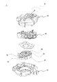
以下、本発明の実施形態について詳細に説明する。なお、以下の説明における軸線方向とは、モータコイル10の軸線方向(ベース部材50におけるリング状部分の軸線方向)をいう。また、上側(上方)とは図1における上側(図2における下側)を、下側(下方)とは図1における下側(図2における上側)をいう。 Hereinafter, embodiments of the present invention will be described in detail. In the following description, the axial direction refers to the axial direction of the motor coil 10 (the axial direction of the ring-shaped portion of the base member 50). Further, the upper side (upper side) means the upper side (lower side in FIG. 2) in FIG. 1, and the lower side (lower side) means the lower side in FIG. 1 (upper side in FIG. 2).
図1に全体を示す本実施形態にかかるモータ装置1は、駆動源であるモータの動力を、動力伝達機構90を介して被駆動体91まで伝達する装置である。これらモータや動力伝達機構90は、上ケース92および下ケース93に収容される。なお、以下で詳細に説明する構成以外の構成(図2から図4に詳細を示した構成以外の構成)は、どのような構成を採用してもよい。例えば、動力伝達機構90としては、図示されるような歯車輪列が挙げられる。また、被駆動体91としては、洗濯機の排水弁が挙げられる。
A
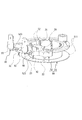
図2から図4に示すように、モータ装置1は、モータコイル10と、このモータコイル10と直列に接続される抵抗体20と、第一の端子30および第二の端子40と、を備える。また、これらの部材は、ベース部材50に取り付けられている。
As shown in FIGS. 2 to 4, the
モータコイル10は、ベース部材50のコイル巻回部51に巻き回されている。コイル巻回部51は、図示されるような軸線方向における両側に鍔部511が形成されたリング状の部分である。この鍔部511の間に巻き付けられた電線がモータコイル10を構成する。かかるモータコイル10に電流が流れることによって発生する磁界により、リング状部分の内側に配置されるモータのロータ60が回転する。
The
抵抗体20は、モータコイル10と直列に接続される電気部品である。抵抗体20は、本体部21とその本体部21の両側から突出したワイヤ状の足(リード線端子)を有する(以下、本体部21の一方側に設けられたものを一方の足22と、本体部21の他方側に設けられたものを他方の足23と称する)。つまり、かかる抵抗体20は、汎用されている一般的なものである。抵抗体20は、次のようにベース部材50の平板部52に保持されている。ベース部材50の平板部52には、二つの壁が抵抗体20の本体部21の幅よりも若干小さい間隔で対向するように形成された抵抗保持部521が設けられている。かかる抵抗保持部521を構成する二つの壁の間に、抵抗体20の本体部21が挟み込まれるようにして保持されている。また、抵抗保持部521の近傍には、ベース部材50の平板部52を貫通する足支持孔522が形成されており、かかる足支持孔522に抵抗体20の両足が挿通されている。具体的には、抵抗体20の一方の足22および他方の足23は、それぞれが根本近傍の所定位置から同じ方向に向けて屈曲しており、当該屈曲した部分が足支持孔522に挿通されている。足支持孔522に挿通された抵抗体20の両足は、その先端(屈曲した部分の先端)から所定長さ部分が平板部52の下側の面から突出している。なお、後述するように、抵抗体20の他方の足23は、第二の端子40に形成された足挿通孔411を通って平板部52の下側の面から突出する。
The
第一の端子30は、基端部31と、この基端部31の一方側から略直交する方向に延びる端末巻回部32と、基端部31の他方側から略直交する方向に延びる電源接続部33と、を有する。本実施形態では、端末巻回部32と電源接続部33とはそれぞれの先端が互いに反対方向を向くように延びる。また、端末巻回部32は、基端部31および電源接続部33より細く、その周面にはモータコイル10の端末を巻き回すための凹凸が形成されている。また、端末巻回部32の断面は、モータコイル10を構成する電線(端末)を切断するためのエッジ(角)のある形状となっている。かかるエッジのある形状とするためには、第一の端子30をプレス打ち抜き加工によって形成すればよい。
The
一方、第二の端子40は、基端部41と、この基端部41の一方側から略直交する方向に延びる抵抗接続部42と、基端部41の他方側から略直交する方向に延びる電源接続部43と、を有する。本実施形態では、第一の端子30における端末巻回部32と第二の端子40における抵抗接続部42は、全く同一の形状を有する。これは、第一の端子30と第二の端子40を共通の金型により製造する(同一の工程により製造する)ためである。したがって、抵抗接続部42は、上記端末巻回部32と同様の凹凸やエッジのある形状となっているが、このような形状でなくてもよい(凹凸やエッジは抵抗接続部42には不要である)。
On the other hand, the
これら第一の端子30および第二の端子40は、次のようにベース部材50の平板部52に固定されている。ベース部材50の平板部52には、外向きに開口した断面が細長い矩形である端子取付穴523が形成されている。平板部52における端子取付穴523が形成された部分の下側の面には、二つの端子取付穴523のそれぞれに繋がる溝5231が形成されている。第一の端子30および第二の端子40は、それぞれの基端部31,41が端子取付穴523に圧入されることによって固定されている。基端部31,41が端子取付穴523に圧入される際、第一の端子30の端末巻回部32および第二の端子40の抵抗接続部42は上記溝5231を通る。各端子の基端部31,41を奥まで圧入すると、第一の端子30の端末巻回部32および第二の端子40の抵抗接続部42は溝5231の最も奥まで入り込んだ位置に位置する。すなわち、平板部52の下側の面から突出した状態となる。
The
また、第二の端子40の基端部41には、貫通孔である足挿通孔411が形成されている。かかる足挿通孔411には、抵抗体20の他方の足23が挿通される。具体的には、足挿通孔411は、第二の端子40の基端部41における抵抗接続部42の根本近傍に形成されている。したがって、足挿通孔411に挿通された抵抗体20の他方の足23と、第二の端子40の抵抗接続部42は互いに沿うように近接した状態で平板部52の下側の面から突出している。なお、このような足挿通孔411があれば、抵抗体20の他方の足23と第二の端子40の抵抗接続部42とを容易に近接した状態とすることができるというだけであって、第二の端子40に必ず足挿通孔411が形成されていなければならないわけではない。また、第一の端子30は足挿通孔411は不要であるが、足挿通孔411を形成することで、第一の端子30と第二の端子40を全く同一の形状とすること(共通化すること)ができる。
Further, a
ベース部材50の所定位置に固定された第一の端子30には、モータコイル10の一方の端末11が直接接続される。具体的には、モータコイル10の一方の端末11は、ベース部材50の平板部52の側面(平板部52の厚み方向に沿う面)に設けられた引掛突起を経由して第一の端子30の端末巻回部32に巻き付けられている。端末巻回部32には、凹凸が形成されているから、この凹凸に引っ掛けるようにしてモータコイル10の一方の端末11が巻き付けられている。この巻き付けられた状態で、ハンダSによってモータコイル10の一方の端末11と端末巻回部32は接合されている。
One
モータコイル10の他方の端末12は、抵抗体20の一方の足22に直接接続されている。具体的には、モータコイル10の他方の端末12は、ベース部材50の平板部52の平面方向に沿って形成された引出溝525に沿って引き出されて抵抗体20の一方の足22に巻き付けられている。この巻き付けられた状態で、ハンダSによってモータコイル10の他方の端末12と抵抗体20の一方の足22は接合されている。
The
このように、モータコイル10の一方の端末11は第一の端子30(端末巻回部32)に、他方の端末12は抵抗体20の一方の足22に巻き付けられる。モータ装置1を製造する際、モータコイル10を構成する電線(導体線)は、次の手順で引き回される。まず、電線を抵抗体20の一方の足22に解けない程度まで巻き付ける。そのまま引出溝525に沿って引き出された電線は、ベース部材50のコイル巻回部51に巻き回される。所定回数(予め定められたモータコイル10の仕様に応じた回数)コイル巻回部51に電線を巻き回した後、引掛突起524を経由して電線を第一の端子30の端末巻回部32に解けない程度まで巻き付ける。十分に第一の端子30の端末巻回部32に巻き付けたら、電線を強く引っ張る。これにより、電線の巻き終わり部分が第一の端子30の端末巻回部32のエッジによって切断され、電線の引き回しが完了する。
Thus, one
一方、ベース部材50の所定位置に固定された第二の端子40には、抵抗体20の他方の足23が直接接続されている。具体的には、上述したように、第二の端子40の抵抗接続部42と抵抗体20の他方の足23とは、互いに沿うように近接した状態で平板部52の下側の面から突出しており、これら二つの軸状の部材を覆うようにハンダSが塗布されることによって、両者が電気的に接続されている。
On the other hand, the
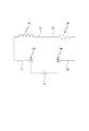
このように接続されることによって、図5に示すようなモータコイル10と抵抗体20が直列に接続された回路が構築される。第一の端子30の電源接続部33および第二の端子40の電源接続部43は、このモータコイル10と抵抗体20を構成要素とする回路に電源Pを接続するための端子となる。第一の端子30の電源接続部33および第二の端子40の電源接続部43に電源Pを接続し、両端子間に電圧が印加されることにより、モータコイル10を構成する電線に電源電圧および抵抗体20の抵抗値に応じた電流が流れる。電流が流れるとモータコイル10から磁界が発生し、モータのロータ60が回転する。
By connecting in this way, a circuit in which the
以上の構成を備える本実施形態にかかるモータ装置1によれば、次のような作用効果が奏される。
According to the
本実施形態にかかるモータ装置1は、モータコイル10に対して直列に抵抗体20が接続された構成であるから、かかる抵抗体20を変える(抵抗体20の抵抗値を変える)ことで様々な電源電圧(商用電源の電圧)に対応した構成とすることができる。つまり、モータコイル10の巻数を増加させるなどの大きな仕様の変更が必要ない。例えば、100V用のモータ装置1を200V用のモータ装置1に変更する場合、200V用のモータ装置1における抵抗体20の抵抗値は、100V用のモータ装置1における抵抗体20の抵抗値よりも所定量大きくすればよい。また、モータ装置1を、抵抗体20を用いずモータコイル10の他方の端末12を第二の端子40の抵抗接続部42に直接接続した仕様に変更することも可能である。
Since the
そして、本実施形態では、ワイヤ状の足を有する一般的な抵抗体20の一方の足22に直接モータコイル10の端末(他方の端末12)を巻き付けているため、抵抗体20を用いたことによる端子の増加を防止できる(モータコイル10の端末を巻き付けるための端子を別途設ける必要がない)。つまり、本実施形態にかかるモータ装置1は、抵抗体20を用いたことによって電源電圧が変化したとしても装置の大きな仕様の変更の必要がなく、かつ、抵抗体20の存在による部品点数の増加がない点で優れるものである。
And in this embodiment, since the terminal (the other terminal 12) of the
また、本実施形態にかかるモータ装置1では、モータコイル10の一方の端末11が巻き付けられる第一の端子30の端末巻回部32、および、モータコイル10の他方の端末12が巻き付けられる抵抗体20の一方の足22は、ともに、ベース部材50の一方側(ベース部材50における平板部52の下側の面)から突出している。つまり、モータコイル10の両端末が巻き付けられる部分が、同じ方向に突出しているため、モータコイル10の端末の巻き付け作業が容易である。加えて、本実施形態のように、第一の端子30の端末巻回部32および抵抗体20の一方の足22と、それぞれに巻き付けられたモータコイル10の端末がハンダSによって接合される構成であれば、両接合部分がベース部材50の一方側から突出しているため、端末巻回部32におけるハンダSによる接合と、抵抗体20の一方の足22におけるハンダSによる接合を一度に行うこと(例えばハンダ槽に接合部分を浸すディッピングによって一度に行うこと)ができ、接合作業が容易である。
In the
また、第二の端子40の抵抗接続部42と抵抗体20の他方の足23とは、互いに沿うように近接した状態で平板部52の下側の面から突出している。したがって、かかる第二の端子40の抵抗接続部42と抵抗体20の他方の足23とのハンダSによる接合を、上記モータコイル10の一方の端末11と第一の端子30のハンダSによる接合、および、モータコイル10の他方の端末12と抵抗体20の一方の足22のハンダSによる接合と一緒に行うことができる。さらに、抵抗体20の一方の足22と他方の足23は、同一の方向を向いているため、ベース部材50に対する抵抗体20の取り付けが容易である。
Further, the
ここで、上記第二の端子40の抵抗接続部42と抵抗体20の他方の足23とのハンダSによる接合を確実に行うために、抵抗体20の他方の足23を固定するための構成を抵抗接続部42に形成するとよい。例えば、抵抗接続部42に貫通孔を形成しておき、ハンダSによる接合前に抵抗体20の他方の足23を屈曲させて当該貫通孔に圧入固定することができるようにするとよい。そうすると、抵抗体20の他方の足23と第二の端子40の抵抗接続部42がより密着した状態となるから、上記ハンダSによる接合をより確実に行うことができる。
Here, in order to securely join the
また、第一の端子30の端末巻回部32の周面には、モータコイル10の一方の端末11が切断可能なエッジが形成されており、モータコイル10を構成する電線を上述した所定の経路で引き回した後、当該エッジによりモータコイル10の一方の端末11の巻き終わり部分を切断することができる。つまり、まず最初に抵抗体20の一方の足22へ電線を巻き付け、ベース部材50のコイル巻回部51にモータコイル10を形成した後、最後に端末巻回部32のエッジで電線を切断すればよいから、モータコイル10の他方の端末12が巻き付けられる抵抗体20の一方の足22に大きな負荷が掛からない(抵抗体20の一方の足22側で電線を切断するといった工程が必要ない)。したがって、電線の切断に必要な引張力に耐えうる高強度の足を有する抵抗体20を用いるといった必要はなく、一般的な抵抗体20を用いることができる。
Moreover, the edge which can cut | disconnect one
また、ベース部材50には、抵抗体20の本体部21を挟み込んで保持する抵抗保持部521が形成されている。そのため、抵抗体20の足が第二の端子40の抵抗接続部42やモータコイル10の他方の端末12に接続されるまで抵抗体20をベース部材50に保持させた状態とすることができ、ハンダSによる接合作業などの接続作業が容易となる。また、抵抗体20の本体部21がベース部材50の抵抗保持部521に保持された状態となるため、その分抵抗体20の足に掛かる負荷が低減される。したがって、抵抗体20の足と、モータコイル10の第二の端子40の抵抗接続部42やモータコイル10の他方の端末12の接続が外れてしまったり、抵抗体20の足が切れてしまったりすることがない。
The
また、抵抗体20の一方の足22は、ベース部材50に形成された足支持孔522によって支持されているため、モータコイル10の他方の端末12を巻き付ける力によって抵抗体20の一方の足22が切れてしまうことなどが防止される。
Further, since one
以上、本発明の実施の形態について詳細に説明したが、本発明は上記実施の形態に何ら限定されるものではなく、本発明の要旨を逸脱しない範囲で種々の改変が可能である。 Although the embodiments of the present invention have been described in detail above, the present invention is not limited to the above-described embodiments, and various modifications can be made without departing from the gist of the present invention.
1 モータ装置
10 モータコイル
11 一方の端末
12 他方の端末
20 抵抗体
21 本体部
22 一方の足
23 他方の足
30 第一の端子
32 端末巻回部
40 第二の端子
42 抵抗接続部
50 ベース部材
521 抵抗保持部
522 足支持孔
S ハンダ
DESCRIPTION OF
Claims (7)
このモータコイルと直列に接続される抵抗体と、
前記モータコイルおよび前記抵抗体を構成要素とする回路に電源を接続するための第一の端子および第二の端子と、を備え、
前記モータコイルの一方の端末は、前記第一の端子に直接接続され、
前記モータコイルの他方の端末は、前記抵抗体の一方の足に直接接続され、
前記抵抗体の他方の足は、前記第二の端子に直接接続されていることを特徴とするモータ装置。 A motor coil;
A resistor connected in series with the motor coil;
A first terminal and a second terminal for connecting a power source to a circuit comprising the motor coil and the resistor as components, and
One end of the motor coil is directly connected to the first terminal;
The other end of the motor coil is directly connected to one leg of the resistor,
The other leg of the resistor is directly connected to the second terminal.
前記モータコイルの一方の端末は、前記第一の端子に設けられた端末巻回部に巻き付けられ、このモータコイルの一方の端末が巻き付けられた端末巻回部と、他方の端末が巻き付けられた前記抵抗体の一方の足は、ともに、前記ベース部材の一方側から突出していることを特徴とする請求項2に記載のモータ装置。 A base member to which the resistor, the first terminal, and the second terminal are attached;
One terminal of the motor coil is wound around a terminal winding part provided in the first terminal, and a terminal winding part around which one terminal of the motor coil is wound and the other terminal are wound. The motor device according to claim 2, wherein one of the legs of the resistor protrudes from one side of the base member.
前記第二の端子は、同じく前記ベース部材の一方側から突出した、前記抵抗体の他方の足と接続される抵抗接続部を有することを特徴とする請求項3に記載のモータ装置。 The other leg of the resistor protrudes from one side of the base member,
4. The motor device according to claim 3, wherein the second terminal includes a resistance connection portion that projects from the one side of the base member and is connected to the other leg of the resistor.
Priority Applications (1)
| Application Number | Priority Date | Filing Date | Title |
|---|---|---|---|
| JP2011070836A JP2012205486A (en) | 2011-03-28 | 2011-03-28 | Motor device |
Applications Claiming Priority (1)
| Application Number | Priority Date | Filing Date | Title |
|---|---|---|---|
| JP2011070836A JP2012205486A (en) | 2011-03-28 | 2011-03-28 | Motor device |
Publications (1)
| Publication Number | Publication Date |
|---|---|
| JP2012205486A true JP2012205486A (en) | 2012-10-22 |
Family
ID=47185888
Family Applications (1)
| Application Number | Title | Priority Date | Filing Date |
|---|---|---|---|
| JP2011070836A Pending JP2012205486A (en) | 2011-03-28 | 2011-03-28 | Motor device |
Country Status (1)
| Country | Link |
|---|---|
| JP (1) | JP2012205486A (en) |
Cited By (1)
| Publication number | Priority date | Publication date | Assignee | Title |
|---|---|---|---|---|
| JP2018026938A (en) * | 2016-08-09 | 2018-02-15 | 日本電産サンキョー株式会社 | Terminal part and motor and drain valve driving device |
Citations (7)
| Publication number | Priority date | Publication date | Assignee | Title |
|---|---|---|---|---|
| JPS62188945U (en) * | 1986-05-20 | 1987-12-01 | ||
| JPH0222078U (en) * | 1988-07-25 | 1990-02-14 | ||
| JPH06315238A (en) * | 1993-03-05 | 1994-11-08 | Fuji Elelctrochem Co Ltd | Bobbin with terminal pin |
| JPH10201160A (en) * | 1997-01-16 | 1998-07-31 | Matsushita Seiko Co Ltd | Stator of brushless motor |
| JP2003270054A (en) * | 2002-03-15 | 2003-09-25 | Ubukata Industries Co Ltd | Sealed heat sensing device |
| JP2005102422A (en) * | 2003-09-25 | 2005-04-14 | Denso Corp | Shift actuator |
| JP2010074013A (en) * | 2008-09-22 | 2010-04-02 | Toyooki Kogyo Kk | Electromagnet apparatus |
-
2011
- 2011-03-28 JP JP2011070836A patent/JP2012205486A/en active Pending
Patent Citations (7)
| Publication number | Priority date | Publication date | Assignee | Title |
|---|---|---|---|---|
| JPS62188945U (en) * | 1986-05-20 | 1987-12-01 | ||
| JPH0222078U (en) * | 1988-07-25 | 1990-02-14 | ||
| JPH06315238A (en) * | 1993-03-05 | 1994-11-08 | Fuji Elelctrochem Co Ltd | Bobbin with terminal pin |
| JPH10201160A (en) * | 1997-01-16 | 1998-07-31 | Matsushita Seiko Co Ltd | Stator of brushless motor |
| JP2003270054A (en) * | 2002-03-15 | 2003-09-25 | Ubukata Industries Co Ltd | Sealed heat sensing device |
| JP2005102422A (en) * | 2003-09-25 | 2005-04-14 | Denso Corp | Shift actuator |
| JP2010074013A (en) * | 2008-09-22 | 2010-04-02 | Toyooki Kogyo Kk | Electromagnet apparatus |
Cited By (1)
| Publication number | Priority date | Publication date | Assignee | Title |
|---|---|---|---|---|
| JP2018026938A (en) * | 2016-08-09 | 2018-02-15 | 日本電産サンキョー株式会社 | Terminal part and motor and drain valve driving device |
Similar Documents
| Publication | Publication Date | Title |
|---|---|---|
| TWI395238B (en) | Magnetic parts | |
| KR101821910B1 (en) | Electric motor, air conditioner, and electric device | |
| JP2010073519A (en) | Coil unit of electromagnetic contactor, and assembling method thereof | |
| JP5997679B2 (en) | Coil parts | |
| JP2015230984A (en) | Coil component and manufacturing method therefor | |
| WO2018012127A9 (en) | Coreless coil and method for manufacturing coreless coil | |
| US9479024B2 (en) | Multi-phase coil terminal structure and motor including same | |
| US10873235B2 (en) | DC motor with a positive temperature coefficient thermistor | |
| JP5319817B1 (en) | Motor structure with soldered terminals soldered to connectors or terminal blocks | |
| WO2017098590A1 (en) | Electric motor stator winding method, electric motor stator, and electric fan motor | |
| JP2012205486A (en) | Motor device | |
| JP2013191693A (en) | Coil component and manufacturing method therefor | |
| JP2016046867A (en) | Rotary electric machine stator | |
| JP6026004B2 (en) | Electric motors, air conditioners and electrical equipment | |
| JP2013030565A (en) | Transformer and manufacturing method therefor and electric power unit | |
| JPWO2014057745A1 (en) | Electric motor, air conditioner, and electric motor manufacturing method | |
| JP2012210015A (en) | Stator structure of motor | |
| JP2000348954A (en) | Choke coil | |
| US10522284B2 (en) | Coil fixing structure | |
| TWI681607B (en) | A motor module | |
| JP6426598B2 (en) | Rotor, method of manufacturing the same, and DC motor | |
| WO2020066563A1 (en) | Coil device and electrical junction box | |
| WO2020066562A1 (en) | Coil device and electrical junction box | |
| JP2016063644A (en) | Motor with electrically caulked terminal and manufacturing method of the same | |
| JP5959380B2 (en) | Manufacturing method of electric motor |
Legal Events
| Date | Code | Title | Description |
|---|---|---|---|
| A621 | Written request for application examination |
Free format text: JAPANESE INTERMEDIATE CODE: A621 Effective date: 20140205 |
|
| A977 | Report on retrieval |
Free format text: JAPANESE INTERMEDIATE CODE: A971007 Effective date: 20141128 |
|
| A131 | Notification of reasons for refusal |
Free format text: JAPANESE INTERMEDIATE CODE: A131 Effective date: 20150106 |
|
| A02 | Decision of refusal |
Free format text: JAPANESE INTERMEDIATE CODE: A02 Effective date: 20150512 |