JP2012205444A - Stator core, method for manufacturing the same, and motor - Google Patents
Stator core, method for manufacturing the same, and motor Download PDFInfo
- Publication number
- JP2012205444A JP2012205444A JP2011069371A JP2011069371A JP2012205444A JP 2012205444 A JP2012205444 A JP 2012205444A JP 2011069371 A JP2011069371 A JP 2011069371A JP 2011069371 A JP2011069371 A JP 2011069371A JP 2012205444 A JP2012205444 A JP 2012205444A
- Authority
- JP
- Japan
- Prior art keywords
- laser
- stator core
- thin plate
- welded portion
- welded
- Prior art date
- Legal status (The legal status is an assumption and is not a legal conclusion. Google has not performed a legal analysis and makes no representation as to the accuracy of the status listed.)
- Withdrawn
Links
Images


Abstract
Description
本発明はモータ(回転電動機)に用いられるステータコアとその製造方法、およびそのステータコアを用いたモータに関する。 The present invention relates to a stator core used in a motor (rotary electric motor), a manufacturing method thereof, and a motor using the stator core.
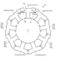
図10は、PMモータに用いられる一般的なステータコア100である。図10(a)はステータコア100の平面図、図10(b)はステータコア100の正面図である。ステータコア100は、強磁性体からなる、中空円板が周方向に複数に分割されたT形の薄板102が、回転軸101方向に積層され、周方向に結合されてなる。T形の薄板102の横棒部分をヨーク104、縦棒部分をティース105という。周方向に隣接する薄板102は、ヨーク104の外周の分割境界のレーザ溶接部103を、レーザ溶接される。薄板102の表面は薄い絶縁膜で覆われているため、積層された薄板102どうしは、レーザ溶接部103を除き、電気的に絶縁されている。
FIG. 10 shows a
図11は、従来のステータコア100の、理想的にレーザ溶接された場合の、レーザ溶接部103の拡大図である。図11(a)はステータコア100の平面図、図11(b)はステータコア100の正面図である。図11(b)に示すように、隣接する左右の薄板102のレーザ溶接部103の中心にスポット的にレーザが照射される。レーザ溶接部103の中心は、薄板102の境界の中心と一致する。この場合、レーザ溶け込み部106は、回転軸方向に隣接する薄板102には及ばない。
FIG. 11 is an enlarged view of the laser welded
レーザ溶け込み部106により、隣接する左右の薄板102は機械的に結合させるのがレーザ溶接の目的である。しかし、隣接する左右の薄板102は電気的にも結合する。薄板102内の渦電流を考慮すると、左右の薄板102が電気的に結合することは望ましくない。しかしレーザ溶接を用いた場合、左右の薄板102を機械的に結合しながら、電気的に絶縁するのは難しい。
The purpose of laser welding is to mechanically couple the adjacent left and right
図11(b)に示すように、理想的にレーザ溶接された場合、レーザ溶け込み部106は、回転軸方向に隣接する薄板102には及ばない。そのため、回転軸方向に隣接する薄板102とは電気的に絶縁される。これは渦電流を考慮すると、望ましい。
As shown in FIG. 11B, when laser welding is ideally performed, the
図12は、現実のレーザ溶接部103の拡大図である。図12(a)はレーザ溶接部103の平面図、図12(b)はレーザ溶接部103の正面図である。ステータコア100は、厚さ0.3mm〜0.5mm程度の薄板102が、200枚〜300枚程度積層されたものである。そのため、ステータコア100全体では、各薄板102の僅かな厚さの誤差が累積され、厚さ方向の累積誤差が一枚の薄板102の厚さを超えることもある。さらに、レーザの位置決め誤差もある。
FIG. 12 is an enlarged view of the
薄板102の厚さ誤差とレーザの位置決め誤差が重なって、現実には、図12(b)に示すように、レーザ溶け込み部106の位置は回転軸方向にばらつくことがある。レーザ溶け込み部106の位置が回転軸方向にばらつくと、図12(b)に示すように、レーザ溶け込み部106は回転軸方向に隣接する薄板102に及ぶことがある。この結果、回転軸方向に隣接する薄板102が電気的に導通する。これは渦電流を考慮すると望ましくない。従って、レーザ溶け込み部106が、回転軸方向に隣接する薄板102に及ばないようにする必要がある。
The thickness error of the
特許文献1に記載されたステータコアでは、ヨークの両端に突出折曲片と切欠部を設ける。ステータコアの組み立ての際、薄板を積層した後、ヨークの突出折曲片を隣のヨークの切欠部に差し込み、突出折曲片を折り曲げて、ヨークを互いに固定する。溶接を行なわないので、回転軸方向に隣接する薄板間の絶縁は保持される。しかし、間隙が各々0.3mm〜0.5mm程度の200箇所〜300箇所の切欠部に、厚さが各々0.3mm〜0.5mm程度の200枚〜300枚の突出折曲片を、1枚のミスもなく確実に差し込まなければならない。 In the stator core described in Patent Document 1, protruding bent pieces and notches are provided at both ends of the yoke. When assembling the stator core, after laminating the thin plates, the protruding bent piece of the yoke is inserted into the notch portion of the adjacent yoke, the protruding bent piece is bent, and the yokes are fixed to each other. Since welding is not performed, the insulation between the thin plates adjacent in the rotation axis direction is maintained. However, 200 to 300 protruding bent pieces each having a thickness of about 0.3 mm to 0.5 mm are provided in 200 to 300 notch portions each having a gap of about 0.3 mm to 0.5 mm. It must be inserted securely without mistakes.
特許文献2に記載されたステータコアでは、ヨークの両端に連結用凹部と連結用凸部を設ける。ステータコアの組み立ての際、薄板を積層した後、ヨークの連結用凸部を隣のヨークの連結用凹部にはめ込み、薄板を互いに固定する。溶接を行なわないので、回転軸方向に隣接する薄板間の絶縁は保持される。しかし、200箇所〜300箇所の連結用凸部を、200箇所〜300箇所の連結用凹部に、1箇所のミスもなく確実にはめ込まなければならない。 In the stator core described in Patent Document 2, a connecting concave portion and a connecting convex portion are provided at both ends of the yoke. When assembling the stator core, after laminating the thin plates, the connecting projections of the yoke are fitted into the connecting recesses of the adjacent yoke, and the thin plates are fixed to each other. Since welding is not performed, the insulation between the thin plates adjacent in the rotation axis direction is maintained. However, the connecting projections at 200 to 300 must be securely fitted into the connecting recesses at 200 to 300 without any mistakes.
特許文献1、2に記載されたステータコアでは、溶接をしないことにより、回転軸方向に隣接する薄板間の絶縁は保持される。しかし、特許文献1、2に記載されたステータコアは量産がかなり難しそうである。 In the stator cores described in Patent Documents 1 and 2, the insulation between the thin plates adjacent to each other in the rotation axis direction is maintained without welding. However, the stator cores described in Patent Documents 1 and 2 are likely to be difficult to mass-produce.
特許文献3に記載されたステータコアでは、薄板を分割しないで、非常に細いつなぎ片部で直線状にヨークをつないだ状態で、打ち抜く。直線状の薄板を積層して、巻線をした後、積層した薄板を円形に曲げて、ステータコアとする。薄板の両端は、例えば、アーク溶接により結合する。薄板の両端をアーク溶接すると、積層した薄板間の電気的絶縁は失われる。また、つなぎ片部は非常に細いと言っても、変形したとき、厚さ方向に膨らむ。そのため回転軸方向のヨークの間に隙間が生じて、ステータコアの磁気特性が低下するおそれがある。 In the stator core described in Patent Document 3, punching is performed without dividing the thin plate, with the yoke being connected linearly by a very thin connecting piece. After laminating linear thin plates and winding them, the laminated thin plates are bent into a circular shape to form a stator core. Both ends of the thin plate are joined by, for example, arc welding. When both ends of the sheet are arc welded, the electrical insulation between the laminated sheets is lost. Even if the connecting piece is very thin, when it is deformed, it swells in the thickness direction. Therefore, a gap is generated between the yokes in the direction of the rotation axis, and the magnetic characteristics of the stator core may be deteriorated.
従来のステータコア100では、薄板102の厚さ誤差とレーザの位置決め誤差が累積して、レーザ溶け込み部106の位置が回転軸方向にばらつき、回転軸方向に隣接する薄板102にレーザ溶け込み部106が及ぶことがある。この結果、回転軸方向に隣接する薄板102が電気的に導通する。これは渦電流を考慮すると望ましくない。
In the
本発明の目的は、薄板の厚さ誤差とレーザの位置決め誤差が従来と変わらない場合でも、回転軸方向に隣接する薄板にレーザ溶け込み部が及ばず、回転軸方向に隣接する薄板との電気絶縁性が維持されるステータコアを実現することである。 The object of the present invention is to provide electrical insulation from a thin plate adjacent in the direction of the rotation axis, even if the thickness error of the thin plate and the positioning error of the laser are not different from the conventional case, the laser penetration portion does not reach the thin plate adjacent in the direction of the rotation axis. This is to realize a stator core that maintains its performance.
(1)本発明は、中空円板を周方向に複数に分割してなり、ヨークとティースを有するT形の薄板が、回転軸方向に積層され、周方向に結合されてなるステータコアである。薄板は、外周または内周の分割部に、レーザ溶接部を備える。薄板は、外周または内周の非分割部に、外周または内周から、後退または突出した非溶接部を備える。レーザ溶接部と非溶接部は、回転軸方向に交互に配置される。 (1) The present invention is a stator core in which a hollow disk is divided into a plurality in the circumferential direction, and a T-shaped thin plate having a yoke and teeth is laminated in the rotation axis direction and joined in the circumferential direction. The thin plate is provided with a laser welded portion at an outer peripheral or inner peripheral divided portion. The thin plate is provided with a non-welded portion that retreats or protrudes from the outer periphery or inner periphery at the non-divided portion at the outer periphery or inner periphery. Laser welded portions and non-welded portions are alternately arranged in the rotation axis direction.
(2)本発明のステータコアの各薄板内において、レーザ溶接の溶け込み部は非溶接部に及ばない。 (2) In each thin plate of the stator core of the present invention, the penetration portion of laser welding does not reach the non-welded portion.
(3)本発明のステータコアにおいて、レーザ溶接部は、積層された各薄板へのスポット溶接により形成される。 (3) In the stator core of the present invention, the laser welded portion is formed by spot welding to each laminated thin plate.
(4)本発明のステータコアにおいて、レーザ溶接部は、回転軸方向の連続溶接により形成される。 (4) In the stator core of the present invention, the laser welded portion is formed by continuous welding in the rotation axis direction.
(5)本発明のステータコアにおいて、レーザ溶接部は直線状または回転軸を中心とする円弧状である。非溶接部は、レーザ溶接部より曲率半径の小さい凹形状である。 (5) In the stator core of the present invention, the laser welded portion is linear or arcuate around the rotation axis. The non-welded part has a concave shape with a smaller radius of curvature than the laser welded part.
(6)本発明のステータコアにおいて、ヨークの非溶接部を含む部分の最狭部の巾は、ヨークの非溶接部を含まない部分の最狭部の巾以上である。 (6) In the stator core of the present invention, the width of the narrowest portion of the portion including the non-welded portion of the yoke is equal to or greater than the width of the narrowest portion of the portion not including the non-welded portion of the yoke.
(7)本発明のステータコアにおいて、レーザ溶接部は直線状または回転軸を中心とする円弧状である。非溶接部は、レーザ溶接部より曲率半径の小さい凸形状である。 (7) In the stator core of the present invention, the laser welded portion has a linear shape or an arc shape centered on the rotation axis. The non-welded part has a convex shape with a smaller radius of curvature than the laser welded part.
(8)本発明のステータコアにおいて、レーザ溶接部付近を除き、積層された薄板の分割境界面は、回転軸方向に同一面をなす。 (8) In the stator core of the present invention, except for the vicinity of the laser welded portion, the divided boundary surfaces of the laminated thin plates are flush with the rotation axis direction.
(9)本発明のステータコアは、ヨークに薄板の周方向の分割境界を有する。 (9) The stator core of the present invention has a dividing boundary in the circumferential direction of the thin plate in the yoke.
(10)本発明のステータコアは、ヨーク外周部にレーザ溶接部および非溶接部を有する。 (10) The stator core of the present invention has a laser welded portion and a non-welded portion on the outer periphery of the yoke.
(11)本発明のステータコアは、レーザ溶接部とスロットの間に溶接熱遮断空隙を有する。 (11) The stator core of the present invention has a welding heat blocking gap between the laser weld and the slot.
(12)本発明のステータコアは、ヨーク内周部にレーザ溶接部および非溶接部を有する。 (12) The stator core of the present invention has a laser welded portion and a non-welded portion on the inner periphery of the yoke.
(13)本発明のステータコアにおいては、巻線後、レーザ溶接部がスロットオープンから溶接される。 (13) In the stator core of the present invention, after winding, the laser weld is welded from the slot open.
(14)本発明のステータコアは、ティース部に薄板の周方向の分割境界を有する。 (14) The stator core of this invention has the division | segmentation boundary of the circumferential direction of a thin plate in a teeth part.
(15)本発明のステータコアは、ティースの内周部にレーザ溶接部を有する。 (15) The stator core of the present invention has a laser welded portion on the inner peripheral portion of the teeth.
(16)本発明のモータは、上記に記載のステータコアを備える。 (16) A motor of the present invention includes the stator core described above.
(17)本発明のステータコアの製造方法は、
外周または内周の分割部にレーザ溶接部を有し、外周または内周の非分割部に、外周または内周から、後退または突出した非溶接部を有する、中空円板を周方向に複数に分割してなり、ヨークとティースを有するT形の薄板を準備するステップと、
前記レーザ溶接部と非溶接部が、回転軸方向に交互に配置されるように、前記薄板を積層するステップと、
積層された前記薄板を周方向に結合するステップと、
前記レーザ溶接部をスポット溶接するステップを含む。
(17) A method for manufacturing a stator core of the present invention includes:
A plurality of hollow discs in the circumferential direction having laser welded portions on the outer peripheral or inner peripheral portion, non-split portions on the outer peripheral or inner periphery, and non-welded portions that are retracted or protruded from the outer peripheral or inner periphery. Preparing a T-shaped thin plate having divided yokes and teeth;
Laminating the thin plates such that the laser welded portions and non-welded portions are alternately arranged in the rotation axis direction;
Coupling the laminated thin plates in the circumferential direction;
Spot welding the laser weld.
(18)本発明のステータコアの製造方法は、
外周または内周の分割部にレーザ溶接部を有し、外周または内周の非分割部に、外周または内周から、後退または突出した非溶接部を有する、中空円板を周方向に複数に分割してなり、ヨークとティースを有するT形の薄板を準備するステップと、
前記レーザ溶接部と非溶接部が、回転軸方向に交互に配置されるように、前記薄板を積層するステップと、
積層された前記薄板を周方向に結合するステップと、
前記レーザ溶接部を連続溶接するステップを含む。
(18) A method for manufacturing a stator core of the present invention includes:
A plurality of hollow discs in the circumferential direction having laser welded portions on the outer peripheral or inner peripheral portion, non-split portions on the outer peripheral or inner periphery, and non-welded portions that are retracted or protruded from the outer peripheral or inner periphery. Preparing a T-shaped thin plate having divided yokes and teeth;
Laminating the thin plates such that the laser welded portions and non-welded portions are alternately arranged in the rotation axis direction;
Coupling the laminated thin plates in the circumferential direction;
Continuously welding the laser weld.
本発明により、薄板の厚さ誤差とレーザの位置決め誤差が従来と変わらない場合でも、回転軸方向に隣接する薄板にレーザ溶け込み部が及ばず、回転軸方向に隣接する薄板との電気絶縁性が維持されるステータコアが実現される。 According to the present invention, even when the thickness error of the thin plate and the positioning error of the laser are not different from the conventional one, the laser penetration portion does not reach the thin plate adjacent in the rotation axis direction, and the electrical insulation with the thin plate adjacent in the rotation axis direction is achieved. A maintained stator core is realized.
本発明のステータコアは、中空円板を周方向に複数に分割してなり、ヨークとティースを有するT形の薄板が、回転軸方向に積層され、周方向に結合されてなる。薄板は、外周または内周の分割部に、レーザ溶接部を備える。薄板は、外周または内周の非分割部に、外周または内周から、後退または突出した非溶接部を備える。レーザ溶接部と非溶接部は、回転軸方向に交互に配置される。 The stator core of the present invention is formed by dividing a hollow disk into a plurality of parts in the circumferential direction, and a T-shaped thin plate having a yoke and teeth is laminated in the direction of the rotation axis and joined in the circumferential direction. The thin plate is provided with a laser welded portion at an outer peripheral or inner peripheral divided portion. The thin plate is provided with a non-welded portion that retreats or protrudes from the outer periphery or the inner periphery in the non-divided portion on the outer periphery or the inner periphery. Laser welded portions and non-welded portions are alternately arranged in the rotation axis direction.
本発明のステータコアにおいては、レーザ照射位置が回転軸方向にばらついても、レーザ溶け込み部は回転軸方向に隣接する薄板に及ばない。例えば、レーザ照射位置が下方にずれて、第1層の薄板のレーザ溶け込み部が下方にずれた場合、第2層の薄板も同時にレーザ照射される。第1層の薄板のレーザ溶接部には、レーザの焦点が合っているため、溶融してレーザ溶け込み部が形成される。しかし、第2層の薄板のレーザ照射部分は、ステータコアの外周または内周から後退した凹形状(または突出した凸形状)の非溶接部であるため、レーザの焦点が合わない。このため、非溶接部はレーザが照射されても溶融しない。従って、レーザ照射位置が下方にずれても、レーザ溶け込み部は第1層の薄板のみに形成される。その結果、第1層の薄板と第2層の薄板の電気的絶縁が維持される。 In the stator core of the present invention, even if the laser irradiation position varies in the rotation axis direction, the laser penetration portion does not reach the thin plate adjacent in the rotation axis direction. For example, when the laser irradiation position is shifted downward and the laser penetration portion of the first layer thin plate is shifted downward, the second layer thin plate is also irradiated with laser simultaneously. Since the laser is focused on the laser welded portion of the first thin plate, the laser melted portion is formed by melting. However, the laser irradiation portion of the thin plate of the second layer is a concave non-welded portion (or a protruding convex shape) retreated from the outer periphery or inner periphery of the stator core, so that the laser is not focused. For this reason, even if a non-welded part is irradiated with a laser, it does not melt. Therefore, even if the laser irradiation position is shifted downward, the laser penetration portion is formed only on the thin plate of the first layer. As a result, the electrical insulation between the thin plate of the first layer and the thin plate of the second layer is maintained.
レーザ溶接部は、ステータコアの外周(回転軸を中心とする円弧状)または内周(回転軸を中心とする円弧状)、あるいはステータコアの外周の接線(直線状)または内周の接線(直線状)が適当である。非溶接部は、レーザの焦点が合わなければよいので、ステータコアの外周あるいは内周から後退した凹形状でもよいし、ステータコアの外周あるいは内周から突出した凸形状でもよい。非溶接部の形状には、円弧状、矩形状などがあり、特に限定はされない。非溶接部が円弧状(円弧に近い形状も含む)の場合、その円弧の曲率半径は、レーザ溶接部の曲率半径より小さいことが望ましい。 The laser welded portion is the outer circumference (arc shape centered on the rotation axis) or inner circumference (arc shape centered on the rotation axis), the outer tangent line (straight line), or the inner circumference tangent line (linear shape). ) Is appropriate. Since the non-welded portion does not have to be focused on the laser, it may have a concave shape that is recessed from the outer periphery or inner periphery of the stator core, or may be a convex shape that protrudes from the outer periphery or inner periphery of the stator core. The shape of the non-welded portion includes an arc shape and a rectangular shape, and is not particularly limited. When the non-welded part has an arc shape (including a shape close to an arc), the radius of curvature of the arc is preferably smaller than the radius of curvature of the laser welded part.
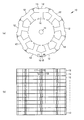
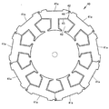
図1は、本発明の一例のステータコア10である。図1(a)はステータコア10の平面図、図1(b)はステータコア10の正面図である。本発明のステータコア10では、強磁性体からなる、中空円板が周方向に複数に分割されたT形の薄板12が、回転軸11方向に積層される。T形の薄板12の横棒部分をヨーク13、縦棒部分をティース14という。ステータコア10では、薄板12がヨーク部で分割されている。図1(a)では、分割線は複数の直線の組合せ(折れ線)であるが、分割線は適当な曲線でもよい。
FIG. 1 shows a
薄板12の表面は薄い絶縁膜で覆われているため、回転軸方向に隣接する薄板12どうしは、電気的に絶縁されている。薄板12のレーザ溶接部15、16がレーザ溶接される。
Since the surfaces of the
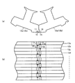
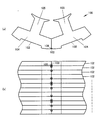
図2は、本発明のステータコア10のレーザ溶接される部分の拡大図である。図2(a)は、第1層の薄板12aの平面図、図2(b)は、第2層の薄板12bの平面図、図2(c)はステータコア10の正面図である。第3層の薄板12cは、第1層の薄板12aと同じ形状であり、第4層の薄板12dは、第2層の薄板12bと同じ形状である。第5層以後も、奇数層は第1層の薄板12aと同じ形状であり、偶数層は第2層の薄板12bと同じ形状である。
FIG. 2 is an enlarged view of a portion of the
第1層の薄板12aは、レーザ溶接部15と非溶接部17を備える。第2層の薄板12bは、レーザ溶接部16と非溶接部18を備える。第3層以降の薄板12c、12d、...も、奇数層はレーザ溶接部15と非溶接部17を備え、偶数層はレーザ溶接部16と非溶接部18を備える。
The first-layer
非溶接部17、18は、ステータコア10の外周から後退した凹形状である。非溶接部17の凹み量h1および非溶接部18の凹み量h2は、凹みによりレーザの焦点が外れ、凹み内部がレーザに照射されても、溶融しないように設定される。非溶接部17の凹み量h1および非溶接部18の凹み量h2は、望ましくは、同じ値に設定される。これにより、奇数層の薄板12a、12c、...と、偶数層の薄板12b、12d、...は線対称形となる。従って、同一形状の薄板12を、表、裏、表、裏、...と積層すると、ステータコア10が形成される。このようにすると打ち抜き金型が1種類で済む。
The
第1層の薄板12aのレーザ溶接部15の中心と、第2層の薄板12bの非溶接部18の中心は、回転軸11方向について一致する。第1層の薄板12aの非溶接部17の中心と、第2層の薄板12bのレーザ溶接部16の中心は、回転軸11方向について一致する。この関係は、第3層以降の薄板12c、12d、...についても同様である。
The center of the laser welded
ヨーク13の、非溶接部17を含む部分の最狭部の巾k1が、非溶接部17を含まない部分の最狭部の巾k1以上となるように、非溶接部17の凹み量h1は設定される。これは隣り合うヨーク13間の磁束の流れを妨げないためである。同様にして、非溶接部18の凹み量h2も設定される。
The dent amount h1 of the
第1層の薄板12aの回転軸11側の分割境界23a、第2層の薄板12bの回転軸11側の分割境界23b、...は、積層されたとき、回転軸方向に一つの面をなすように設定される。これにより、ステータコア10の分割面の精度向上と垂直磁束低減が実現される。
The dividing
図3は、本発明のステータコア10の、理想的にレーザ溶接された場合の、レーザ溶接部15、16の拡大図である(図3はスポット溶接の場合を示す)。図3(a)は平面図、図3(b)は正面図である。図3(b)に示すように、第1層の薄板12aのレーザ溶接部15の中心に、スポット的にレーザが照射される。レーザ溶け込み部19の中心は、レーザ溶接部15の中心と一致する。レーザ溶け込み部19は、隣接する下の薄板12bに及ばない。従って、第1層の薄板12aと第2層の薄板12bは、電気的に絶縁される。
FIG. 3 is an enlarged view of the laser welded
第2層の薄板12bのレーザ溶接部16の中心に、スポット的にレーザが照射される。レーザ溶け込み部20の中心は、レーザ溶接部16の中心と一致する。レーザ溶け込み部20は、隣接する上の薄板12aおよび下の薄板12cに及ばない。従って、第1層の薄板12a、第2層の薄板12b、第3層の薄板12cは、電気的に絶縁される。この関係は、第3層以降の薄板12c、12d、...についても同様である。
The laser is spot-irradiated at the center of the laser welded
図4は、スポット的にレーザ溶接されたレーザ溶接部15、16の現実の状態の拡大図である。図4(a)は平面図、図4(b)は正面図である。ステータコア10は、厚さ0.3mm〜0.5mm程度の薄板102が、200枚〜300枚程度積層されて形成される。そのため、ステータコア10全体では、各薄板12の僅かな厚さの誤差が累積され、厚さ方向の累積誤差が一枚の薄板12の厚さを超えることもある。さらに、レーザの位置決め誤差も考慮しなければならない。
FIG. 4 is an enlarged view of the actual state of the laser welds 15 and 16 that are laser-welded in a spot manner. 4A is a plan view and FIG. 4B is a front view. The
薄板12の厚さ誤差とレーザの位置決め誤差が重なって、現実には、図4(b)に示すように、レーザ溶け込み部19、20の位置は回転軸方向にばらつくことがある。しかし図4(b)に示すように、本発明のステータコア10においては、レーザ溶け込み部19、20の位置が回転軸方向にばらついても、レーザ溶け込み部19、20は回転軸方向に隣接する薄板12に及ばない。
The thickness error of the
例えば、第1層の薄板12aのレーザ溶け込み部19は下方にずれている。その原因はレーザ照射位置が下方にずれているためである。このときレーザは、第1層の薄板12aと第2層の薄板12bを同時に照射する。第1層の薄板12aのレーザ溶接部15には、レーザの焦点が合っているため、溶融してレーザ溶け込み部19が形成される。しかし、第2層の薄板12bのレーザ照射部分は、ステータコア10の外周から後退した凹形状である非溶接部18であるため、レーザの焦点が合わない。このため、非溶接部18はレーザが照射されても溶融しない。従って、レーザ照射位置は下方にずれているが、レーザ溶け込み部19は第1層の薄板12aのみに形成される。その結果、第1層の薄板12aと第2層の薄板12bの電気的絶縁が維持される。
For example, the
同様の原理により、レーザ照射位置が回転軸方向にずれても、第2層の薄板12bのレーザ溶け込み部20は、第1層の薄板12aまたは第3層の薄板12cに及ばない。従って、第2層の薄板12bのレーザ溶け込み部20により、第2層の薄板12bと、第1層の薄板12aおよび第3層の薄板12cの間の電気的絶縁が破壊されることはない。
Based on the same principle, even if the laser irradiation position is shifted in the rotation axis direction, the
同様のことが、ステータコア10を形成する全ての薄板12a、12b、12c、12d、...について言える。従って、レーザ照射位置が回転軸方向にずれても、全ての薄板12a、12b、12c、12d、...間の回転軸方向の絶縁は維持される。
The same applies to all the
1枚の薄板の中で、レーザ溶け込み部19が非溶接部17に達すると、非溶接部17が溶融して、回転軸方向に隣接する薄板12どうしの絶縁が失われるおそれがある。そのため、レーザ溶け込み部19が非溶接部17に及ばない距離に、レーザ溶接部15と非溶接部17は離される。同様に、レーザ溶け込み部20が非溶接部18に及ばない距離に、レーザ溶接部16と非溶接部18は離される。
If the
レーザ照射位置が回転軸方向にずれても、回転軸方向に隣接する薄板12どうしの絶縁が維持される原理を利用すると、レーザはスポット照射ではなく、回転軸方向の連続照射でもよい。連続照射の方がスポット照射より制御が容易である。
Even if the laser irradiation position is shifted in the rotation axis direction, the laser may be irradiated continuously in the rotation axis direction instead of spot irradiation if the principle of maintaining insulation between the
図5は、回転軸方向に連続的にレーザ溶接されたレーザ溶接部15、16の模式図である。図5(a)は平面図、図5(b)は正面図である。図4のスポット溶接の場合とは異なり、レーザを回転軸方向に移動させるとき、レーザの強度は一定でもよい。 FIG. 5 is a schematic view of the laser welds 15 and 16 continuously laser-welded in the direction of the rotation axis. FIG. 5A is a plan view and FIG. 5B is a front view. Unlike the spot welding in FIG. 4, when the laser is moved in the direction of the rotation axis, the intensity of the laser may be constant.
レーザが下方(回転軸方向)に移動しながら、第1層の薄板12aのレーザ溶接部15を照射すると、レーザ溶接部15には焦点が合うため、レーザ溶接部15は溶融し、レーザ溶け込み部21が形成される。レーザが第2層の薄板12bに移動すると、レーザ照射部分は、ステータコア10の外周から後退した凹形状の非溶接部18であるため、レーザの焦点が合わない。このため、非溶接部18はレーザが照射されても溶融しない。従って、レーザが第2層の薄板12bを下方に移動しながら照射しても、第2層の薄板12bにはレーザ溶け込み部が形成されない。
If the
次にレーザが下方(回転軸方向)に移動しながら、第3層の薄板12cのレーザ溶接部15を照射すると、レーザ溶接部15には焦点が合うため、レーザ溶接部15は溶融し、レーザ溶け込み部21が形成される。レーザが第4層の薄板12dに移動すると、レーザ照射部分は、凹形状の非溶接部18であるため、レーザの焦点が合わない。このため、レーザが第4層の薄板12cを下方に移動しながら照射しても、第4層の薄板12dにはレーザ溶け込み部が形成されない。
Next, when the
このようにして、第1層の薄板12aのレーザ溶接部15、第3層の薄板12cのレーザ溶接部15など、奇数層の薄板12のレーザ溶接部15のレーザ溶け込み部21が形成される。偶数層の薄板12にはレーザ溶け込み部が形成されない。
In this way, the laser penetration portion 21 of the laser welded
次にレーザの照射ラインを、第2層の薄板12bのレーザ溶接部16に移動させて、レーザを下方(回転軸方向)に移動させる。上記と同様にして、第2層の薄板12bのレーザ溶接部16にはレーザ溶け込み部22が形成されるが、第1層の薄板12a、第3層の薄板12cにはレーザ溶け込み部が形成されない。これを繰り返して、第2層の薄板12bのレーザ溶接部16、第4層の薄板12dのレーザ溶接部16など、偶数層の薄板12のレーザ溶接部16のレーザ溶け込み部22が形成される。奇数層の薄板12にはレーザ溶け込み部が形成されない。
Next, the laser irradiation line is moved to the
もしレーザ溶け込み部21が非溶接部17に達すると、非溶接部17が溶融して、回転軸方向に隣接する薄板12どうしの絶縁が失われるおそれがある。そのため、レーザ溶け込み部21が非溶接部17に及ばない距離に、レーザ溶接部15と非溶接部17は離される。同様に、レーザ溶け込み部22が非溶接部18に及ばない距離に、レーザ溶接部16と非溶接部18は離される。
If the laser penetration part 21 reaches the
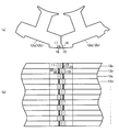
図6は、本発明の他の例のステータコア30のレーザ溶接される部分の拡大図である。図6(a)は、第1層の薄板31aの平面図、図6(b)は、第2層の薄板31bの平面図、図6(c)はステータコア30の正面図である。第3層の薄板31cは、第1層の薄板31aと同じ形状であり、第4層の薄板31dは、第2層の薄板31bと同じ形状である。第5層以後も、奇数層は第1層の薄板31aと同じ形状であり、偶数層は第2層の薄板31b同じ形状である。
FIG. 6 is an enlarged view of a laser welded portion of a
第1層の薄板31aは、レーザ溶接部32と非溶接部33を備える。第2層の薄板31bは、レーザ溶接部34と非溶接部35を備える。第3層以降も、奇数層はレーザ溶接部32と非溶接部33を備え、偶数層はレーザ溶接部34と非溶接部35を備える。非溶接部33、35は、ステータコア30の外周から突き出た凸形状である。非溶接部33の突き出し量h3および非溶接部35の突き出し量h4は、レーザの焦点が外れ、突き出し部がレーザに照射されても、溶融しないように設定される。非溶接部33の突き出し量h3および非溶接部35の突き出しh4は、望ましくは、同じ値に設定される。これにより、奇数層の薄板31a、31c、...と、偶数層の薄板31b、31d、...は線対称形となる。従って、同一形状の薄板31を、表、裏、表、裏、...と積層すると、ステータコア30が形成される。このようにすると打ち抜き金型が1種類で済む。レーザ溶接部32、34は、ステータコア30の外周に沿った円弧状あるいは、ステータコア30の外周の接線である直線状である。
The first layer
図6のように、レーザ溶接部32と非溶接部35を回転軸方向に設け、レーザ溶接部34と非溶接部33を回転軸方向に設けることにより、ステータコア30は、ステータコア10と同様、スポットレーザ溶接および連続レーザ溶接のいずれの場合も、軸方向に隣接する薄板31間の絶縁が維持される。これによれば、非溶接部33によりヨークの幅が制限されることがないため、磁気飽和が回避できる。
As shown in FIG. 6, by providing the laser welded
図7は、本発明の他の例のステータコア40の、第1層の薄板41aの平面図である。薄板41aは、レーザ溶接部42とスロット43の間に、溶接熱遮断空隙44を有する。溶接熱遮断空隙44は、図7の場合、隣接する薄板41a間に設けられた貫通孔である。溶接熱遮断空隙44の孔形状は特に制限はない。スロット43の周囲には熱に弱い絶縁材45がある。溶接熱遮断空隙44により、レーザ溶接の熱により絶縁材45が劣化することが防止される。
FIG. 7 is a plan view of the first layer
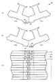
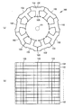
図8は、本発明の他の例のステータコア50の平面図である。ステータコア50は、第1層の薄板51a、第2層の薄板51b、第3層の薄板51c、...が積層されてなる。第1層の薄板51aは、レーザ溶接部52と非溶接部53を備える。第2層の薄板51bは、レーザ溶接部54と非溶接部55を備える。第3層以降の薄板51c、51d、...も、奇数層はレーザ溶接部52と非溶接部53を備え、偶数層はレーザ溶接部54と非溶接部55を備える。非溶接部53、55は、ヨーク56の内周から後退した凹形状である。非溶接部53の凹み量h5および非溶接部55の凹み量h6は、凹みによりレーザの焦点が外れ、凹み内部がレーザに照射されても、溶融しないように設定される。非溶接部53の凹み量h5および非溶接部55の凹み量h6は、望ましくは、同じ値に設定される。これにより、奇数層の薄板51a、51c、...と、偶数層の薄板51b、51d、...は線対称形となる。従って、同一形状の薄板51を、表、裏、表、裏、...と積層すると、ステータコア50が形成される。このようにすると打ち抜き金型が1種類で済む。
FIG. 8 is a plan view of a
ステータコア50においては、スロット57に巻線を行なった後、スロットオープン58からレーザを照射して、レーザ溶接部52、54を溶接することもできる。これにより、整列巻きが可能となる。また、平角線であっても、高占積率で巻回することができる。
In the
図9は、本発明の他の例のステータコア60の平面図である。ステータコア60は、第1層の薄板61a、第2層の薄板61b、第3層の薄板61c、...が積層されてなる。ステータコア60においては、薄板61a、61b、61c、...がティース62内で分割されている。第1層の薄板61aは、レーザ溶接部63と非溶接部64を備える。第2層の薄板61bは、レーザ溶接部65と非溶接部66を備える。第3層以降の薄板61c、61d、...も、奇数層はレーザ溶接部63と非溶接部64を備え、偶数層はレーザ溶接部65と非溶接部66を備える。非溶接部64、66は、ティース62の内周から後退した凹形状である。非溶接部64の凹み量h7および非溶接部66の凹み量h8は、凹みによりレーザの焦点が外れ、凹み内部がレーザに照射されても、溶融しないように設定される。非溶接部64の凹み量h7および非溶接部66の凹み量h8は、望ましくは、同じ値に設定される。これにより、奇数層の薄板61a、61c、...と、偶数層の薄板61b、61d、...は線対称形となる。従って、同一形状の薄板61を、表、裏、表、裏、...と積層すると、ステータコア60が形成される。このようにすると打ち抜き金型が1種類で済む。このとき、図6のように、非溶接部を凸形状とすることは望ましくない。そのようにすると、非溶接部がエアギャップに突出し、ロータと接触するからである。
FIG. 9 is a plan view of a
本発明のステータコア10、30、40、50(ティース内で分割したステータコア60は除く)は、集中巻に好適に用いられる。集中巻で用いる場合、分割状態のステータコアのティースに巻線後、ステータコアを結合し、必要なレーザ溶接を行なうことができるため、生産性が高い。
The
本発明のステータコアは、分布巻にも用いられる。分布巻で用いる場合、ステータコアを結合し、必要なレーザ溶接を行なった後、巻線を行なう。 The stator core of the present invention is also used for distributed winding. When used in distributed winding, the stator core is coupled, and necessary winding is performed after laser welding.
上記の説明は、インナーロータに適したステータコアであったが、本発明のステータコアは、アウターロータにも用いられる。本発明のステータコアをアウターロータに用いる場合、上記の説明の「ステータコアの外周」を「ステータコアの内周」と読み替えればよい。 Although the above description is a stator core suitable for an inner rotor, the stator core of the present invention is also used for an outer rotor. When the stator core of the present invention is used for the outer rotor, “the outer periphery of the stator core” in the above description may be read as “the inner periphery of the stator core”.
本発明のステータコアは、PMモータ、シンクロナスリラクタンスモータ、スイッチドリラクタンスモータに好適に用いられる。 The stator core of the present invention is suitably used for PM motors, synchronous reluctance motors, and switched reluctance motors.
10 ステータコア
11 回転軸
12、12a、12b、12c、12d 薄板
13 ヨーク
14 ティース
15、16 レーザ溶接部
17、18 非溶接部
19、20、21、22 レーザ溶け込み部
23a、23b 分割境界
30 ステータコア
31、31a、31b、31c、31d 薄板
32、34 レーザ溶接部
33、35 非溶接部
40 ステータコア
41a 薄板
42 レーザ溶接部
43 スロット
44 溶接熱遮断空隙
45 絶縁材
50 ステータコア
51a、51b、51c、51d 薄板
52、54 レーザ溶接部
53、55 非溶接部
56 ヨーク
57 スロット
58 スロットオープン
60 ステータコア
61a、61b、61c、61d 薄板
62 ティース
63、65 レーザ溶接部
64、66 非溶接部
100 ステータコア
101 回転軸
102 薄板
103 レーザ溶接部
104 ヨーク
105 ティース
106 レーザ溶け込み部
DESCRIPTION OF
Claims (18)
前記薄板の外周または内周の分割部に備えられたレーザ溶接部と、
前記薄板の外周または内周の非分割部に、外周または内周から、後退または突出した非溶接部を備え、
前記レーザ溶接部と前記非溶接部は、前記回転軸方向に交互に配置されたステータコア。 A stator core formed by dividing a hollow disk into a plurality in the circumferential direction, a T-shaped thin plate having a yoke and teeth, laminated in the rotation axis direction and coupled in the circumferential direction,
A laser welded portion provided on the outer periphery or inner periphery of the thin plate;
The non-divided portion of the outer periphery or inner periphery of the thin plate is provided with a non-welded portion that retreats or protrudes from the outer periphery or the inner periphery,
The laser welded portion and the non-welded portion are stator cores arranged alternately in the rotation axis direction.
前記レーザ溶接部と非溶接部が、回転軸方向に交互に配置されるように、前記薄板を積層するステップと、
積層された前記薄板を周方向に結合するステップと、
前記レーザ溶接部をスポット溶接するステップを含むステータコアの製造方法。 A plurality of hollow discs in the circumferential direction having laser welded portions on the outer peripheral or inner peripheral portion, non-split portions on the outer peripheral or inner periphery, and non-welded portions that are retracted or protruded from the outer peripheral or inner periphery. Preparing a T-shaped thin plate having divided yokes and teeth;
Laminating the thin plates such that the laser welded portions and non-welded portions are alternately arranged in the rotation axis direction;
Coupling the laminated thin plates in the circumferential direction;
A method for manufacturing a stator core, comprising spot welding the laser weld.
前記レーザ溶接部と非溶接部が、回転軸方向に交互に配置されるように、前記薄板を積層するステップと、
積層された前記薄板を周方向に結合するステップと、
前記レーザ溶接部を連続溶接するステップを含むステータコアの製造方法。 A plurality of hollow discs in the circumferential direction having laser welded portions on the outer peripheral or inner peripheral portion, non-split portions on the outer peripheral or inner periphery, and non-welded portions that are retracted or protruded from the outer peripheral or inner periphery. Preparing a T-shaped thin plate having divided yokes and teeth;
Laminating the thin plates such that the laser welded portions and non-welded portions are alternately arranged in the rotation axis direction;
Coupling the laminated thin plates in the circumferential direction;
A method for manufacturing a stator core, comprising continuously welding the laser weld.
Priority Applications (1)
| Application Number | Priority Date | Filing Date | Title |
|---|---|---|---|
| JP2011069371A JP2012205444A (en) | 2011-03-28 | 2011-03-28 | Stator core, method for manufacturing the same, and motor |
Applications Claiming Priority (1)
| Application Number | Priority Date | Filing Date | Title |
|---|---|---|---|
| JP2011069371A JP2012205444A (en) | 2011-03-28 | 2011-03-28 | Stator core, method for manufacturing the same, and motor |
Publications (1)
| Publication Number | Publication Date |
|---|---|
| JP2012205444A true JP2012205444A (en) | 2012-10-22 |
Family
ID=47185852
Family Applications (1)
| Application Number | Title | Priority Date | Filing Date |
|---|---|---|---|
| JP2011069371A Withdrawn JP2012205444A (en) | 2011-03-28 | 2011-03-28 | Stator core, method for manufacturing the same, and motor |
Country Status (1)
| Country | Link |
|---|---|
| JP (1) | JP2012205444A (en) |
Cited By (5)
| Publication number | Priority date | Publication date | Assignee | Title |
|---|---|---|---|---|
| WO2014115271A1 (en) * | 2013-01-23 | 2014-07-31 | 三菱電機株式会社 | Stator core and electric motor |
| CN109309412A (en) * | 2018-11-20 | 2019-02-05 | 卧龙电气集团股份有限公司 | The manufacturing method of stator, motor and stator |
| WO2020050535A1 (en) * | 2018-09-03 | 2020-03-12 | 엘지이노텍 주식회사 | Motor |
| CN114069909A (en) * | 2021-12-08 | 2022-02-18 | 安徽美芝精密制造有限公司 | Stator, motor, compressor and electrical equipment |
| WO2023103668A1 (en) * | 2021-12-08 | 2023-06-15 | 安徽美芝精密制造有限公司 | Stator, motor, compressor, and electrical device |
-
2011
- 2011-03-28 JP JP2011069371A patent/JP2012205444A/en not_active Withdrawn
Cited By (6)
| Publication number | Priority date | Publication date | Assignee | Title |
|---|---|---|---|---|
| WO2014115271A1 (en) * | 2013-01-23 | 2014-07-31 | 三菱電機株式会社 | Stator core and electric motor |
| WO2020050535A1 (en) * | 2018-09-03 | 2020-03-12 | 엘지이노텍 주식회사 | Motor |
| US11942823B2 (en) | 2018-09-03 | 2024-03-26 | Lg Innotek Co., Ltd. | Motor |
| CN109309412A (en) * | 2018-11-20 | 2019-02-05 | 卧龙电气集团股份有限公司 | The manufacturing method of stator, motor and stator |
| CN114069909A (en) * | 2021-12-08 | 2022-02-18 | 安徽美芝精密制造有限公司 | Stator, motor, compressor and electrical equipment |
| WO2023103668A1 (en) * | 2021-12-08 | 2023-06-15 | 安徽美芝精密制造有限公司 | Stator, motor, compressor, and electrical device |
Similar Documents
| Publication | Publication Date | Title |
|---|---|---|
| JP5299514B2 (en) | Rotor and method for manufacturing the same | |
| JP5126414B2 (en) | Rotor and method for manufacturing the same | |
| JP2012205444A (en) | Stator core, method for manufacturing the same, and motor | |
| CN108781029B (en) | Method for manufacturing rotor | |
| JP2013165615A (en) | Positioning device of segment coil | |
| JP4730461B2 (en) | Magnetic core manufacturing method | |
| CN110431735B (en) | Core manufacturing method and core | |
| JP2012205446A (en) | Rotor core, method for manufacturing the same, and motor | |
| JP2012228133A (en) | Stator core and method for manufacturing the same | |
| JP6210003B2 (en) | Stator core, rotating electric machine, and stator core manufacturing method | |
| WO2020170413A1 (en) | Method for welding copper-containing members, and method for manufacturing dynamo-electric machine | |
| JPWO2020100311A1 (en) | Stator manufacturing method | |
| WO2021144900A1 (en) | Stator and method for manufacturing stator | |
| JP2018121396A (en) | Manufacturing method for coil | |
| JP2023022764A (en) | Stator and method for manufacturing stator | |
| JP5720891B2 (en) | Stator and manufacturing method thereof | |
| JP6965465B2 (en) | Manufacturing method of laminated iron core and laminated iron core | |
| JP7331670B2 (en) | Stator for rotating electrical machine and method for manufacturing stator for rotating electrical machine | |
| WO2019087339A1 (en) | Armature core of rotary electric machine, core-block coupled body, and manufacturing method for armature core of rotary electric machine | |
| JP2019062683A (en) | Armature for rotary electric machine and method for manufacturing the same | |
| JP2013017292A (en) | Rotor core and manufacturing method of the same | |
| JP6922118B2 (en) | Stator manufacturing method | |
| JP7211128B2 (en) | Laminated structure manufacturing method | |
| JP2018117440A (en) | Rotary electric machine | |
| JP6696455B2 (en) | Rotating electric machine rotor |
Legal Events
| Date | Code | Title | Description |
|---|---|---|---|
| A300 | Withdrawal of application because of no request for examination |
Free format text: JAPANESE INTERMEDIATE CODE: A300 Effective date: 20140603 |