JP2012205332A - Vehicle monitoring device and vehicle monitoring system using the same - Google Patents
Vehicle monitoring device and vehicle monitoring system using the same Download PDFInfo
- Publication number
- JP2012205332A JP2012205332A JP2011065248A JP2011065248A JP2012205332A JP 2012205332 A JP2012205332 A JP 2012205332A JP 2011065248 A JP2011065248 A JP 2011065248A JP 2011065248 A JP2011065248 A JP 2011065248A JP 2012205332 A JP2012205332 A JP 2012205332A
- Authority
- JP
- Japan
- Prior art keywords
- signal
- vehicle
- railway vehicle
- abnormality detection
- acceleration
- Prior art date
- Legal status (The legal status is an assumption and is not a legal conclusion. Google has not performed a legal analysis and makes no representation as to the accuracy of the status listed.)
- Pending
Links
Images
Abstract
Description
本発明は、鉄道車両等の車両の監視装置及びこれを用いた車両の監視システムに関するものである。 The present invention relates to a monitoring device for a vehicle such as a railway vehicle and a vehicle monitoring system using the same.
下記特許文献1には、鉄道車両等の交通機関の運転状況を監視する運転状況監視システムとして、前記交通機関を運転するときに要求される運転条件とこの交通機関の現在の運転状況とを比較する運転状況比較手段と、前記運転状況比較手段の比較結果に基づいて、前記交通機関の現在の運転状況の妥当性を判定する運転状況判定手段と、を備える運転状況監視システムが、開示されている。
In
また、下記特許文献1には、設備機器の操作状況を監視する操作状況監視システムとして、前記設備機器を操作するときに要求される操作条件とこの設備機器の現在の操作状況とを比較する操作状況比較手段と、前記操作状況比較手段の比較結果に基づいて前記設備機器の現在の操作状況の妥当性を判定する操作状況判定手段と、を備える操作状況監視システムも、開示されている。
Further, in
しかしながら、前記従来の運転状況監視システムでは、交通機関を運転するときに要求される運転条件とこの交通機関の現在の運転状況とを比較し、その比較結果に基づいて交通機関の現在の運転状況の妥当性を判定している。したがって、前記従来の運転状況監視システムでは、予め定められた当初の運転条件とは異なる運転条件に応じた運転操作を運転者が意図して行っても、当該交通機関の現在の運転状況が当初の運転条件に従った運転状況のまま継続してしまうような異常事態(例えば、運転者が危険回避等のために急減速操作を行っても、交通機関が減速することなく、その操作前の速度を維持してしまうような異常事態)を、検知することができなかった。 However, the conventional driving situation monitoring system compares the driving conditions required when driving the transportation with the current driving situation of the transportation, and based on the comparison result, the current driving situation of the transportation. Judging the validity of. Therefore, in the conventional driving situation monitoring system, even if the driver intends to perform a driving operation according to a driving condition different from a predetermined initial driving condition, the current driving situation of the transportation system is initially An abnormal situation in which the driving condition is continued according to the driving conditions (for example, even if the driver performs a sudden deceleration operation to avoid danger etc., the transportation system does not decelerate, An abnormal situation that would maintain the speed) could not be detected.
また、前記従来の操作状況監視システムでは、設備機器を操作するときに要求される操作条件とこの設備機器の現在の操作状況とを比較し、その比較結果に基づいて設備機器の現在の操作状況の妥当性を判定している。したがって、この設備機器が鉄道車両等である場合において、操作者が予め定められた操作条件に従う操作をしていれば、鉄道車両等の車両がその操作条件に従わない挙動を行うような異常事態(例えば、運転者が予め定められた通りに減速操作をしているにも拘わらず、当該車両が加速してしまうような異常事態)を、検知することはできなかった。 In the conventional operation status monitoring system, the operation condition required when operating the equipment is compared with the current operation status of the equipment, and the current operation status of the equipment is determined based on the comparison result. Judging the validity of. Therefore, when this equipment is a railway vehicle or the like, if the operator performs an operation in accordance with a predetermined operation condition, an abnormal situation in which the vehicle such as the railway vehicle behaves in a manner that does not comply with the operation condition. (For example, an abnormal situation in which the vehicle accelerates despite the driver performing a deceleration operation as determined in advance) could not be detected.
このように、従来の運転状況監視システムや操作状況監視システムでは、鉄道車両等の車両の異常事態を適切に検知することはできなかった。 As described above, the conventional driving situation monitoring system and operation situation monitoring system cannot properly detect an abnormal situation of a vehicle such as a railway vehicle.
本発明は、このような事情に鑑みてなされたもので、鉄道車両等の車両の異常事態をより適切に検知することができる車両の監視装置、及び、これを用いた車両の監視システムを提供することを目的とする。 The present invention has been made in view of such circumstances, and provides a vehicle monitoring apparatus that can more appropriately detect an abnormal situation of a vehicle such as a railway vehicle, and a vehicle monitoring system using the same. The purpose is to do.
前記課題を解決するための手段として、以下の各態様を提示する。第1の態様による車両監視装置は、車両の挙動を検出する検出手段と、前記検出手段により検出された前記挙動と前記車両の運転操作部からの運転操作信号とに基づいて、前記検出手段により検出された前記挙動が、前記車両の運転操作部からの運転操作信号に基づいて予め定められた異常挙動条件に該当するか否かを判定し、前記異常挙動条件に該当する場合に異常検知信号を発生する異常検知処理手段と、を備えたものである。 The following aspects are presented as means for solving the problems. The vehicle monitoring apparatus according to the first aspect is configured to detect, based on the detection means for detecting the behavior of the vehicle, the behavior detected by the detection means, and the driving operation signal from the driving operation unit of the vehicle. It is determined whether the detected behavior corresponds to a predetermined abnormal behavior condition based on a driving operation signal from the driving operation unit of the vehicle, and an abnormality detection signal is detected when the abnormal behavior condition is satisfied. And an abnormality detection processing means for generating.
この第1の態様では、異常検知処理手段が、前記検出手段により検出された車両の挙動と前記車両の運転操作部からの運転操作信号とに基づいて、前記検出手段により検出された前記挙動が、前記車両の運転操作部からの運転操作信号に基づいて予め定められた異常挙動条件に該当するか否かを判定し、前記異常挙動条件に該当する場合に異常検知信号を発生する。したがって、この第1の態様によれば、正常であれば運転操作部の操作状態からは生じ得ない車両の異常挙動によって、車両の異常を検知することができるため、前述した従来の監視システムでは検知し得なかった車両の異常事態を、適切に検知することができる。 In this first aspect, the abnormality detection processing means detects the behavior detected by the detection means based on the behavior of the vehicle detected by the detection means and the driving operation signal from the driving operation section of the vehicle. Based on the driving operation signal from the driving operation unit of the vehicle, it is determined whether or not a predetermined abnormal behavior condition is met, and an abnormal detection signal is generated when the abnormal behavior condition is met. Therefore, according to the first aspect, since the abnormality of the vehicle can be detected by the abnormal behavior of the vehicle that cannot be generated from the operation state of the driving operation unit if it is normal, in the conventional monitoring system described above, An abnormal situation of the vehicle that could not be detected can be detected appropriately.
第2の態様による車両の監視装置は、前記第1の態様において、前記挙動が、前記車両の加減速度、あるいは、前記車両の加減速度及び速度であるものである。この第2の態様は、車両の挙動の具体例を挙げたものである。 In the vehicle monitoring apparatus according to a second aspect, in the first aspect, the behavior is the acceleration / deceleration of the vehicle, or the acceleration / deceleration and speed of the vehicle. This second aspect is a specific example of the behavior of the vehicle.
第3の態様による車両の監視装置は、前記第1又は第2の態様において、前記車両が鉄道車両であり、前記運転操作部が、前記運転操作信号としてノッチ信号を発生するマスコンを含むものである。この第3の態様は、前記車両として、鉄道車両の例を挙げたものである。もっとも、前記第1及び第2の態様では、前記車両は、鉄道車両に限定されるものではなく、例えば、道路を走行する自動車等でもよい。 The vehicle monitoring apparatus according to a third aspect is the vehicle monitoring apparatus according to the first or second aspect, wherein the vehicle is a railway vehicle, and the driving operation unit includes a master controller that generates a notch signal as the driving operation signal. In the third aspect, an example of a railway vehicle is given as the vehicle. But in the said 1st and 2nd aspect, the said vehicle is not limited to a rail vehicle, For example, the motor vehicle etc. which drive | work a road may be sufficient.
第4の態様による車両の監視装置は、前記第1乃至第3のいずれかの態様において、前記異常検知処理手段は、前記検出手段により検出された前記挙動が、前記異常挙動条件に所定時間継続して該当する場合にのみ前記異常検知信号を発生するものである。 The vehicle monitoring apparatus according to a fourth aspect is the vehicle monitoring apparatus according to any one of the first to third aspects, wherein the abnormality detection processing unit continues the behavior detected by the detection unit for a predetermined time in the abnormal behavior condition. Therefore, the abnormality detection signal is generated only in the case where it corresponds.
この第4の態様によれば、前記検出手段により検出された前記挙動が、前記異常挙動条件に所定時間継続して該当する場合にのみ前記異常検知信号を発生するので、信号ノイズ等による誤検知を防止することができるため、好ましい。もっとも、前記第1乃至第3の態様では、前記異常検知処理手段は、前記検出手段により検出された前記挙動が、前記異常挙動条件に瞬間的に該当する場合にも前記異常検知信号を発生してもよい。 According to the fourth aspect, since the abnormality detection signal is generated only when the behavior detected by the detection means continuously corresponds to the abnormal behavior condition for a predetermined time, an erroneous detection due to signal noise or the like is generated. Can be prevented, which is preferable. However, in the first to third aspects, the abnormality detection processing unit generates the abnormality detection signal even when the behavior detected by the detection unit instantaneously corresponds to the abnormal behavior condition. May be.
第5の態様による車両の監視装置は、前記第1乃至第4のいずれかの態様において、前記異常検知信号に応答して、当該異常検知信号発生時及び/又は当該異常検知信号の発生前後に渡る所定期間の、前記車両の各部の状態を示す情報を記録する記録手段を、備えたものである。 The vehicle monitoring apparatus according to a fifth aspect is the vehicle monitoring apparatus according to any one of the first to fourth aspects, wherein the abnormality detection signal is generated and / or before and after the abnormality detection signal is generated in response to the abnormality detection signal. Recording means for recording information indicating the state of each part of the vehicle over a predetermined period of time is provided.
この第5の態様によれば、前記記録手段を備えているので、前記記録手段により記録された情報を用いることで、異常の発生原因の究明が容易になる。 According to the fifth aspect, since the recording unit is provided, the cause of the abnormality can be easily determined by using the information recorded by the recording unit.
第6の態様による車両の監視システムは、前記第1乃至第5のいずれかの態様による車両の監視装置と、前記異常検知信号に応答して前記車両の運転者に警報を発する警報手段と、を備えたものである。 A vehicle monitoring system according to a sixth aspect includes a vehicle monitoring device according to any one of the first to fifth aspects, an alarm unit that issues an alarm to a driver of the vehicle in response to the abnormality detection signal, It is equipped with.
この第6の態様によれば、前記警報手段を備えているので、運転者は異常状態に応じて適切に対処することが可能となる。 According to the sixth aspect, since the alarm means is provided, the driver can appropriately cope with the abnormal state.
本発明によれば、鉄道車両等の車両の異常事態をより適切に検知することができる車両の監視装置、及び、これを用いた車両の監視システムを提供することができる。 ADVANTAGE OF THE INVENTION According to this invention, the monitoring apparatus of the vehicle which can detect the abnormal condition of vehicles, such as a railway vehicle, more appropriately, and the monitoring system of a vehicle using the same can be provided.
以下、本発明による車両の監視装置及び車両の監視システムについて、図面を参照して説明する。 Hereinafter, a vehicle monitoring device and a vehicle monitoring system according to the present invention will be described with reference to the drawings.
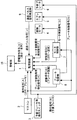
図1は、本発明の一実施の形態による車両の監視装置1及びこれと共に鉄道車両(図示せず)に搭載された関連要素2〜10を模式的に示す概略ブロック図である。
FIG. 1 is a schematic block diagram schematically showing a
前記鉄道車両には、本実施の形態による監視装置1の他、マスコン2と、予備ブレーキ用操作スイッチ3と、当該鉄道車両が走行するための動力を発生する駆動モータ4と、エアブレーキ等の主ブレーキ5と、予備ブレーキ6と、モータ制御部7と、ブレーキ制御部8と、速度パルス信号発生部9と、警報部10とが搭載されている。
In addition to the
本実施の形態では、マスコン2及び予備ブレーキ用操作スイッチ3が、運転操作信号を発生する運転操作部を構成している。
In the present embodiment, the
マスコン2は、主幹制御器とも呼ばれ、前記鉄道車両の運転台に設置されている。マスコン2は、当該鉄道車両の走行に関する力行(アクセル)、ブレーキ及びニュートラル等の運転操作信号を発生するための主ハンドルのノッチ位置を有している。本実施の形態では、図面には示していないが、マスコン2は、P1〜P6,N,B1〜B7,EBの各ノッチ位置を有し、主ハンドルが各ノッチ位置に位置しているときに、運転操作信号として、対応するノッチ信号を出力する。マスコン2は、P1〜P6のノッチ位置では、力行に相当するノッチ信号を発生し、P1〜P6の順に力行の度合いが高くなるノッチ信号を発生する。マスコン2は、B1〜B7のノッチ位置では、ブレーキに相当するノッチ信号を発生し、B1〜B7の順にブレーキの度合いが高くなるノッチ信号を発生する。マスコン2は、EBのノッチ位置では、ブレーキ力の大きい緊急ブレーキに相当するノッチ信号を発生する。マスコン2は、Nのノッチ位置では、アクセルもブレーキも作動させない中立に相当するノッチ信号を発生する。なお、以下の説明では、各ノッチ位置のノッチ信号も、対応するノッチ位置と同じ符号を付して説明する。図1では、マスコン2が発生するノッチ信号P1〜P6,N,B1〜B7,EBを、操作信号[A]と総称している。
The
予備ブレーキ用操作スイッチ3は、マスコン2とは別に前記鉄道車両の運転台付近に設置され、予備ブレーキ6をオンオフさせる運転操作信号を発生する。予備ブレーキ6は、マスコン2の各ノッチ信号B1〜B7,EBに応じて作動する主ブレーキ5とは別個に設けられている。図1では、この運転操作信号を操作信号[B]と称している。以下の説明では、操作信号[B]のうち、予備ブレーキ6をオンさせる信号を「オン信号」、予備ブレーキ6をオフさせる信号を「オフ信号」と呼ぶ。
The spare brake operation switch 3 is installed in the vicinity of the cab of the railway vehicle, separately from the
なお、図面には示していないが、前記鉄道車両には、非常時に操作する非常操作部が設けられている。この非常操作部を操作することで、パンタグラフを下げることにより当該鉄道車両に対する電力供給を遮断したり、当該鉄道車両に対する電力供給部を電気的に短絡させて過電流遮断器を作動させて主電源回路を遮断したりすることができるようになっている。 Although not shown in the drawings, the railway vehicle is provided with an emergency operation unit that is operated in an emergency. By operating this emergency operation part, the power supply to the railway vehicle is cut off by lowering the pantograph, or the power supply part for the railway vehicle is electrically short-circuited to activate the overcurrent breaker to operate the main power supply. The circuit can be shut off.
駆動モータ4は、モータ制御部7による制御下で、当該鉄道車両の走行に関する駆動力を発生する。主ブレーキ5は、ブレーキ制御部8による制御下で、当該鉄道車両の走行に関する制動力を発生する。予備ブレーキ6は、保安ブレーキであり、直通予備ブレーキと呼ばれる場合もある。予備ブレーキ6は、主ブレーキ5とは別系統で、予備ブレーキ用操作スイッチ3からオン信号を受けて作動して、当該鉄道車両の走行に関する強力な制動力を発生する。
The drive motor 4 generates a driving force related to travel of the railway vehicle under the control of the
図1では、駆動モータ4、主ブレーキ5及び予備ブレーキ6をそれぞれ1つしか示していないが、実際には、それぞれ当該鉄道車両に複数搭載される。また、図1では、マスコン2及び予備ブレーキ用操作スイッチ3をそれぞれ1つしか示していないが、実際には、それぞれ上り用の運転台と下り用の運転台に1つずつ搭載される。
In FIG. 1, only one drive motor 4, main brake 5, and
モータ制御部7は、マスコン2からの操作信号[A]のうちのノッチ信号P1〜P6を受けているときに、駆動モータ4が当該ノッチ信号に応じた駆動力を発生する(力行動作を行う)ように、モータ制御信号[C]を駆動モータ4に供給する。また、モータ制御部7は、操作信号[A]のうちのノッチ信号B1〜B7を受けているときに、駆動モータ4が回生動作を行うように、モータ制御信号[C]を駆動モータ4に供給する。
When the
また、モータ制御部7は、公知の自己診断機能を有し、駆動モータ4が異常である(これは、例えば、駆動モータ4に流れる電流量等に基づいて検知し得る。)か否か及びモータ制御部7が異常である(これは、ソフトウエアやハードウエアによるウォッチドックタイマー等により検知し得る。)か否かを診断し、駆動モータ4やモータ制御部7に異常がある場合に、その異常を示すモータ制御異常検知信号[F]を発生し、このモータ制御異常検知信号[F]を監視装置1に供給する。
Further, the
さらに、モータ制御部7は、駆動モータ4が力行及び回生のいずれの動作を行っているかを示す状態信号[E]を発生し、この状態信号[E]を監視装置1に供給する。
Further, the
ブレーキ制御部8は、マスコン2からの操作信号[A]のうちのノッチ信号B1〜B7,EBを受けているときに、主ブレーキ5が当該ノッチ信号に応じた制動力を発生するように、ブレーキ制御信号[D]を主ブレーキ5に供給する。
When receiving the notch signals B1 to B7 and EB of the operation signal [A] from the
また、ブレーキ制御部8は、公知の自己診断機能を有し、主ブレーキ5が異常である(これは、例えば、主ブレーキに設けられている空気圧センサ等の信号に基づいて検知し得る。)か否か及びブレーキ制御部8が異常である(これは、ソフトウエアやハードウエアによるウォッチドックタイマー等により検知し得る。)か否かを診断し、主ブレーキ5やブレーキ制御部8に異常がある場合に、その異常を示すブレーキ制御異常検知信号[H]を発生し、このブレーキ制御異常検知信号[H]を監視装置1に供給する。
The
さらに、ブレーキ制御部8は、自身がマスコン2からノッチ信号B1〜B7,EBのいずれを受けたと認識しているかを示す状態信号[G]を発生し、この状態信号[G]を監視装置1に供給する。
Further, the
速度パルス信号発生部9は、当該鉄道車両の車輪の回転に比例した周期のパルス信号(速度パルス信号[J])を発生する公知の発生器である。この速度パルス信号[J]は、監視装置1に供給される。
The speed
警報部10は、監視装置1から供給される警報指令信号[K]に応答して、運転者に警報を発する。この警報は、視覚的な表示による警報及び音声による警報の両方でもよいし、いずれか一方のみでもよい。この警報部10としては、当該鉄道車両の運転台に設けられている表示部やスピーカーを用いてもよいし、既存の表示部やスピーカーとは別に警報専用の表示部やブザー等を設けてもよい。本発明の一実施の形態による車両の監視システムは、監視装置1と警報部10とによって構成されている。
The
なお、当該鉄道車両の運転者は、警報部10からの警報に応じて、前記非常操作部を操作するなどの対処を行うことができる。
The driver of the railway vehicle can take measures such as operating the emergency operation unit in response to an alarm from the
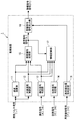
図2は、図1中の監視装置1を模式的に示す概略ブロック図である。本実施の形態による監視装置1は、速度演算部11と、加減速度演算部12と、操作信号判定部13と、状態信号判定部14と、異常検知処理部15と、警報指令信号出力部16と、情報記録部17と、異常検知信号判定部18とを備えている。なお、これらの各要素は、ハードウエアにより実現してもよいし、CPU等を用いてソフトウエアにより実現してもよい。
FIG. 2 is a schematic block diagram schematically showing the
速度演算部11は、速度パルス信号発生部9からの速度パルス信号[J]に基づいて、当該鉄道車両の走行速度を演算する。速度演算部11は、速度パルス信号発生部9と共に、当該鉄道車両の挙動としての当該鉄道車両の速度(走行速度)を検出する速度検出手段を構成している。加減速度演算部12は、速度パルス信号[J]に基づいて、当該鉄道車両の加減速度を演算する。加減速度演算部12は、速度パルス信号発生部9と共に、当該鉄道車両の挙動としての当該鉄道車両の走行の加減速度を検出する加減速度検出手段を構成している。なお、前記速度検出手段や加減速度検出手段は、例えばGPSや速度パルス+GPSなど、速度パルス信号発生部9を用いた構成に限らない。本実施の形態では、速度パルス信号発生部9、速度演算部11及び加減速度演算部12が、当該鉄道車両の挙動を検出する検出手段を構成している。このように、本実施の形態では、当該鉄道車両の挙動として当該鉄道車両の加減速度及び速度の両方を検出している。もっとも、本発明では、後述するように、当該鉄道車両の挙動として当該鉄道車両の加減速度のみを検出してもよい。
The
操作信号判定部13は、マスコン2から得られている操作信号[A]がノッチ信号P1〜P6,N,B1〜B7,EBにいずれであるか、及び、予備ブレーキ用操作スイッチ3から得られている操作信号[B]がオン信号及びオフ信号のいずれであるかを、判定する。
The operation
異常検知処理部15は、加減速度演算部12及び速度演算部11により検出された当該鉄道車両の挙動(本実施の形態では、当該鉄道車両の加減速度及び速度)と当該鉄道車両の運転操作部からの運転操作信号(本実施の形態では、マスコン2及び予備ブレーキ用操作スイッチ3からの操作信号[A],[B]、すなわち、本実施の形態では、操作信号判定部13の判定結果)とに基づいて、加減速度演算部12及び速度演算部11により検出された当該鉄道車両の挙動(本実施の形態では、当該鉄道車両の加減速度及び速度)が、当該鉄道車両の運転操作部からの運転操作信号(本実施の形態では、操作信号[A],[B])に基づいて予め定められた異常挙動条件に該当するか否かを判定し、前記異常挙動条件に該当する場合に異常検知信号[L]を発生する。
The abnormality
本実施の形態では、異常検知処理部15は、加減速度演算部12及び速度演算部11により検出された当該鉄道車両の挙動が、前記異常挙動条件に所定時間(例えば、数秒)継続して該当する場合にのみ前記異常検知信号を発生する。この所定時間は、例えば5秒とすることができるが、他の値に適宜変更してもよい。なお、この所定時間は、後述する全ての個別異常挙動条件について同一であってもよいし、各個別異常挙動条件毎に適宜設定してもよい。また、前記所定時間は、適宜変更して設定し得るようにしておくことが好ましい。なお、本発明では、異常検知処理部15は、加減速度演算部12及び速度演算部11により検出された当該鉄道車両の挙動が、前記異常挙動条件に瞬間的に該当する場合にも前記異常検知信号を発生してもよい。
In the present embodiment, the abnormality
前記異常挙動条件として、例えば、以下に説明する第1乃至第14の個別異常挙動条件のオアとして設定することができ、下記第1乃至第14の個別異常挙動条件のいずれかに該当した場合に、前記異常挙動条件に該当するものとすることができる。なお、以下の説明において、加減速度が正である場合には速度が増加していく加速度を意味し、加減速度が負である場合には速度が低下していく減速度を意味する。 As the abnormal behavior condition, for example, it can be set as the OR of first to fourteenth individual abnormal behavior conditions described below, and when any of the following first to fourteenth abnormal behavior conditions is met In this case, the abnormal behavior condition may be satisfied. In the following description, when the acceleration / deceleration is positive, it means acceleration that increases, and when the acceleration / deceleration is negative, it means deceleration that decreases.
第1の個別異常挙動条件は、マスコン2から操作信号[A]としてノッチ信号P1〜P6のいずれかが得られ、かつ、予備ブレーキ用操作スイッチ3から操作信号[B]としてオン信号が得られている場合において、当該鉄道車両の加減速度が+a1 km/h/sよりも大きいという条件、である。ここで、値a1は、例えば0.0とすることができるが、0.5などの他の値に適宜変更してもよい。
As the first individual abnormal behavior condition, any one of the notch signals P1 to P6 is obtained as the operation signal [A] from the
第2の個別異常挙動条件は、マスコン2から操作信号[A]としてノッチ信号P1が得られ、かつ、予備ブレーキ用操作スイッチ3から操作信号[B]としてオフ信号が得られている場合において、当該鉄道車両の速度がv2 km/h未満であり、かつ、当該鉄道車両の加減速度が+a2 km/h/s未満であるという条件、である。ここで、値v2は例えば2.5とし、値a2は例えば0.0とすることができるが、これらの値は他の値に適宜変更してもよい。
The second individual abnormal behavior condition is that when the notch signal P1 is obtained as the operation signal [A] from the
第3の個別異常挙動条件は、マスコン2から操作信号[A]としてノッチ信号P2が得られ、かつ、予備ブレーキ用操作スイッチ3から操作信号[B]としてオフ信号が得られている場合において、当該鉄道車両の速度がv3 km/h未満であり、かつ、当該鉄道車両の加減速度が+a3 km/h/s未満であるという条件、である。ここで、値v3は例えば14.0とし、値a3は例えば0.0とすることができるが、これらの値は他の値に適宜変更してもよい。
The third individual abnormal behavior condition is that when the notch signal P2 is obtained as the operation signal [A] from the
第4の個別異常挙動条件は、マスコン2から操作信号[A]としてノッチ信号P3〜P6のいずれかが得られ、かつ、予備ブレーキ用操作スイッチ3から操作信号[B]としてオフ信号が得られている場合において、当該鉄道車両の速度がv4 km/h以上であり、かつ、当該鉄道車両の加減速度が+a4 km/h/s未満であるという条件、である。ここで、値v4は例えば14.0とし、値a4は例えば0.0とすることができるが、これらの値は他の値に適宜変更してもよい。
As for the fourth individual abnormal behavior condition, any one of the notch signals P3 to P6 is obtained as the operation signal [A] from the
第5の個別異常挙動条件は、マスコン2から操作信号[A]としてノッチ信号B1が得られている場合において、当該鉄道車両の速度がv5 km/hより大きく、かつ、当該鉄道車両の加減速度が−a5 km/h/s以上であるという条件、である。ここで、値v5は例えば0.0とし、値a5は例えば0.3とすることができるが、これらの値は他の値に適宜変更してもよい。
The fifth individual abnormal behavior condition is that when the notch signal B1 is obtained as the operation signal [A] from the
第6の個別異常挙動条件は、マスコン2から操作信号[A]としてノッチ信号B2が得られている場合において、当該鉄道車両の速度がv6 km/hより大きく、かつ、当該鉄道車両の加減速度が−a6 km/h/s以上であるという条件、である。ここで、値v6は例えば0.0とし、値a6は例えば0.6とすることができるが、これらの値は他の値に適宜変更してもよい。
The sixth individual abnormal behavior condition is that when the notch signal B2 is obtained as the operation signal [A] from the
第7の個別異常挙動条件は、マスコン2から操作信号[A]としてノッチ信号B3が得られている場合において、当該鉄道車両の速度がv7 km/hより大きく、かつ、当該鉄道車両の加減速度が−a7 km/h/s以上であるという条件、である。ここで、値v7は例えば0.0とし、値a7は例えば0.8とすることができるが、これらの値は他の値に適宜変更してもよい。
The seventh individual abnormal behavior condition is that when the notch signal B3 is obtained as an operation signal [A] from the
第8の個別異常挙動条件は、マスコン2から操作信号[A]としてノッチ信号B4が得られている場合において、当該鉄道車両の速度がv8 km/hより大きく、かつ、当該鉄道車両の加減速度が−a8 km/h/s以上であるという条件、である。ここで、値v8は例えば0.0とし、値a8は例えば1.1とすることができるが、これらの値は他の値に適宜変更してもよい。
The eighth individual abnormal behavior condition is that when the notch signal B4 is obtained as the operation signal [A] from the
第9の個別異常挙動条件は、マスコン2から操作信号[A]としてノッチ信号B5が得られている場合において、当該鉄道車両の速度がv9 km/hより大きく、かつ、当該鉄道車両の加減速度が−a9 km/h/s以上であるという条件、である。ここで、値v9は例えば0.0とし、値a9は例えば1.4とすることができるが、これらの値は他の値に適宜変更してもよい。
The ninth individual abnormal behavior condition is that when the notch signal B5 is obtained as the operation signal [A] from the
第10の個別異常挙動条件は、マスコン2から操作信号[A]としてノッチ信号B6が得られている場合において、当該鉄道車両の速度がv10 km/hより大きく、かつ、当該鉄道車両の加減速度が−a10 km/h/s以上であるという条件、である。ここで、値v10は例えば0.0とし、値a10は例えば1.7とすることができるが、これらの値は他の値に適宜変更してもよい。
The tenth individual abnormal behavior condition is that when the notch signal B6 is obtained as an operation signal [A] from the
第11の個別異常挙動条件は、マスコン2から操作信号[A]としてノッチ信号B7が得られている場合において、当該鉄道車両の速度がv11 km/hより大きく、かつ、当該鉄道車両の加減速度が−a11 km/h/s以上であるという条件、である。ここで、値v11は例えば0.0とし、値a11は例えば2.0とすることができるが、これらの値は他の値に適宜変更してもよい。
The eleventh individual abnormal behavior condition is that when the notch signal B7 is obtained as the operation signal [A] from the
第12の個別異常挙動条件は、マスコン2から操作信号[A]としてノッチ信号EBが得られている場合において、当該鉄道車両の速度がv12 km/hより大きく、かつ、当該鉄道車両の加減速度が−a12 km/h/s以上であるという条件、である。ここで、値v12は例えば0.0とし、値a12は例えば2.9とすることができるが、これらの値は他の値に適宜変更してもよい。
The twelfth individual abnormal behavior condition is that when the notch signal EB is obtained as the operation signal [A] from the
第13の個別異常挙動条件は、マスコン2から操作信号[A]としてノッチ信号Nが得られ、かつ、予備ブレーキ用操作スイッチ3から操作信号[B]としてオフ信号が得られている場合において、当該鉄道車両の加減速度が+a13 km/h/s以上であるという条件、である。ここで、値a13は例えば2.2とすることができるが、この値は他の値に適宜変更してもよい。
The thirteenth individual abnormal behavior condition is that when the notch signal N is obtained as the operation signal [A] from the
第14の個別異常挙動条件は、マスコン2から操作信号[A]としてノッチ信号Nが得られ、かつ、予備ブレーキ用操作スイッチ3から操作信号[B]としてオフ信号が得られている場合において、当該鉄道車両の加減速度が−a14 km/h/s以下であるという条件、である。ここで、値a14は例えば4.8とすることができるが、この値は他の値に適宜変更してもよい。
In the 14th individual abnormal behavior condition, when the notch signal N is obtained as the operation signal [A] from the
なお、各個別異常挙動条件における速度や加速度の値は、適宜変更して設定し得るようにしておくことが好ましい。 In addition, it is preferable that the speed and acceleration values in each individual abnormal behavior condition can be appropriately changed and set.
前記異常挙動条件は、この例に限定されるものではない。例えば、前記第1乃至第14の個別異常挙動条件のうち、第1、第13及び第14の個別異常挙動条件のみを採用し、これら3つの個別異常挙動条件のオアを前記異常挙動条件としてもよい。この場合、これらの個別異常挙動条件には当該鉄道車両の速度の条件が含まれていないので、当該鉄道車両の挙動として当該鉄道車両の加減速度のみを検出してもよい。 The abnormal behavior condition is not limited to this example. For example, among the first to fourteenth individual abnormal behavior conditions, only the first, thirteenth and fourteenth individual abnormal behavior conditions are adopted, and the OR of these three individual abnormal behavior conditions is used as the abnormal behavior condition. Good. In this case, since the individual abnormal behavior condition does not include the speed condition of the railway vehicle, only the acceleration / deceleration of the railway vehicle may be detected as the behavior of the railway vehicle.
また、前記個別異常挙動条件では、当該鉄道車両の走行地点の勾配等の要因で場合分けがされていない。しかしながら、前記例における1つの個別異常挙動条件を、当該鉄道車両の走行地点が平坦であるか上り勾配であるか下り勾配であるかに応じて(各走行地点の勾配状況は既知であるので、走行地点(具体的にはキロ程等)に応じて)、場合分けしてもよい。 In the individual abnormal behavior condition, the case is not classified due to factors such as the gradient of the travel point of the railway vehicle. However, one individual abnormal behavior condition in the above example is determined depending on whether the traveling point of the railway vehicle is flat, uphill or downhill (since the gradient status of each running point is known, Depending on the travel point (specifically, about a kilometer, etc.), it may be divided into cases.
本実施の形態では、いずれの個別異常挙動条件に該当したかの情報を情報記録部17が記録し得るように、異常検知処理部15は、異常検知信号[L]として、いずれの個別異常挙動条件に該当したにより異なる種類の異常検知信号を出力するようになっている。もっとも、情報記録部17はいずれの個別異常挙動条件に該当したかの情報を必ずしも記録する必要はなく、その場合には、異常検知処理部15は、いずれの個別異常挙動条件に該当したかに拘わらず、異常検知信号[L]として1種類の異常検知信号を出力してもよい。
In the present embodiment, the abnormality
警報指令信号出力部16は、異常検知処理部15からの異常検知信号[L]に応答して、警報指令信号[K]として、異常挙動の旨の警報を警報部10(図1参照)に発生させるための指令信号を発生し、その指令信号を警報部10に供給する。この指令信号に応答して、警報部10は、異常挙動の旨の警報を発生する。
In response to the abnormality detection signal [L] from the abnormality
異常検知信号判定部18は、モータ制御部7からモータ制御異常検知信号[F]が得られているか否か、及び、ブレーキ制御部8からブレーキ制御異常検知信号[H]が得られている否かを、判定する。
The abnormality detection
本実施の形態では、警報指令信号出力部16は、異常検知信号判定部18の判定結果に従って、モータ制御部7からモータ制御異常検知信号[F]が得られている場合には、警報指令信号[K]として、モータ制御異常の旨の警報を警報部10に発生させるための指令信号を発生し、その指令信号を警報部10に供給する。この指令信号に応答して、警報部10は、モータ制御異常の旨の警報を発生する。また、警報指令信号出力部16は、異常検知信号判定部18の判定結果に従って、ブレーキ制御部8からブレーキ制御異常検知信号[H]が得られている場合には、警報指令信号[K]として、ブレーキ制御異常の旨の警報を警報部10に発生させるための指令信号を発生し、その指令信号を警報部10に供給する。この指令信号に応答して、警報部10は、ブレーキ制御異常の旨の警報を発生する。
In the present embodiment, the alarm command
状態信号判定部14は、モータ制御部7から得られている状態信号[E]が力行及び回生のいずれを示しているか、及び、ブレーキ制御部8からの状態信号[G]はブレーキ制御部8がノッチ信号B1〜B7,EBのいずれを受けていると認識していることを示しているかを、判定する。
The state
情報記録部17は、異常検知処理部15からの異常検知信号[L]に応答して、当該異常検知信号[L]発生時及び/又は当該異常検知信号[L]の発生前後に渡る所定期間の、当該鉄道車両の各部の状態を示す情報を、記録媒体(図示せず)に記録する。
In response to the abnormality detection signal [L] from the abnormality
具体的には、例えば、情報記録部17は、異常検知信号[L]発生時の情報として、その発生時刻、当該鉄道車両の編成構成、当該鉄道車両の列車番号、後方駅名、駅間キロ程、操作信号[A]として得られているノッチ信号の種類、当該鉄道車両の速度、当該鉄道車両の加減速度、各部の電圧、各部の空気圧、該当した個別異常挙動条件の種別を記録する。また、例えば、情報記録部17は、異常検知信号[L]の発生前後に渡る所定期間(例えば、発生3分前から発生3分後に渡る6分間)における、所定サンプリング周期(例えば、500msec)毎の各サンプリング時での、サンプリング時刻、操作信号[A]として得られているノッチ信号の種類、操作信号[B]がオン信号及びオフ信号のいずれであるか、当該鉄道車両の速度、当該鉄道車両の加減速度、状態信号判定部14による判定結果(状態信号[E]が力行及び回生のいずれを示しているか、及び、ブレーキ制御部8からの状態信号[G]はブレーキ制御部8がノッチ信号B1〜B7,EBのいずれを受けていると認識していることを示しているか)を、記録する。
Specifically, for example, the
本実施の形態では、前述したように、異常検知処理部15が、加減速度演算部12及び速度演算部11により検出された当該鉄道車両の挙動(本実施の形態では、当該鉄道車両の加減速度及び速度)と当該鉄道車両の運転操作部からの運転操作信号(本実施の形態では、マスコン2及び予備ブレーキ用操作スイッチ3からの操作信号[A],[B]、すなわち、本実施の形態では、操作信号判定部13の判定結果)とに基づいて、加減速度演算部12及び速度演算部11により検出された当該鉄道車両の挙動(本実施の形態では、当該鉄道車両の加減速度及び速度)が、当該鉄道車両の運転操作部からの運転操作信号(本実施の形態では、操作信号[A],[B])に基づいて予め定められた異常挙動条件に該当するか否かを判定し、前記異常挙動条件に該当する場合に異常検知信号[L]を発生する。
In the present embodiment, as described above, the abnormality
したがって、本実施の形態によれば、正常であればマスコン2及び予備ブレーキ用操作スイッチ3の操作状態からは生じ得ない当該鉄道車両の異常挙動によって、当該鉄道車両の異常を検知することができるため、前述した従来の監視システムでは検知し得なかった車両の異常事態を、適切に検知することができる。
Therefore, according to the present embodiment, the abnormality of the railway vehicle can be detected based on the abnormal behavior of the railway vehicle that cannot be generated from the operation state of the
ところで、本実施の形態では、前述したように、モータ制御部7が自己診断機能を有し、駆動モータ4やモータ制御部7に異常がある場合に、その異常を示すモータ制御異常検知信号[F]を発生する。また、本実施の形態では、前述したように、ブレーキ制御部8が自己診断機能を有し、主ブレーキ5やブレーキ制御部8に異常がある場合に、その異常を示すブレーキ制御異常検知信号[H]を発生する。したがって、モータ制御部7の自己診断機能やブレーキ制御部8の自己診断機能によっても、当該鉄道車両の異常状態を検知することができるので、好ましい。
By the way, in the present embodiment, as described above, when the
本実施の形態と異なり、モータ制御部7の自己診断機能やブレーキ制御部8の自己診断機能のみによって当該鉄道車両の異常状態を検知することとし、異常検知処理部15を取り除いてしまえば、モータ制御部7やブレーキ制御部8の自己診断機能が損なわれたり、異常検知信号[F],[H]を伝送する伝送路が断線したりしてしまうと、モータ制御部7のモータ制御動作や駆動モータ4に異常が発生したりブレーキ制御部8のブレーキ制御動作や主ブレーキ5に異常が発生したりして、当該鉄道車両が異常挙動をしても、その異常状態を全く検知し得ない。
Unlike the present embodiment, the abnormal state of the railway vehicle is detected only by the self-diagnosis function of the
これに対し、本実施の形態では、異常検知処理部15を備えているので、モータ制御部7やブレーキ制御部8の自己診断機能が損なわれたり、異常検知信号[F],[H]を伝送する伝送路が断線したりしてしまっても、正常であればマスコン2及び予備ブレーキ用操作スイッチ3の操作状態からは生じ得ない当該鉄道車両の異常挙動によって、当該鉄道車両の異常を検知することができる。
On the other hand, in this embodiment, since the abnormality
また、本実施の形態では、前述したように、異常検知処理部15は、加減速度演算部12及び速度演算部11により検出された当該鉄道車両の挙動が、前記異常挙動条件に所定時間(例えば、数秒)継続して該当する場合にのみ前記異常検知信号を発生する。したがって、本実施の形態によれば、信号ノイズ等による誤検知を防止することができるため、好ましい。
Further, in the present embodiment, as described above, the abnormality
さらに、本実施の形態では、前述したように、情報記録部17によって、異常検知処理部15からの異常検知信号[L]に応答して前記情報を記録する。したがって、本実施の形態によれば、この情報を用いることで、異常の発生原因の究明が容易になる。
Furthermore, in this embodiment, as described above, the
以上、本発明の実施の形態について説明したが、本発明は前記実施の形態に限定されるものではない。例えば、前記情報記録部17は必ずしも設けなくてもよい。また、モータ制御部7やブレーキ制御部8は、必ずしも自己診断機能を有していなくてもよい。さらに、本発明は、モータ制御の鉄道車両に限らず、エンジン制御の気動車等の他の鉄道車両や、道路を走行する自動車等の鉄道車両以外の種々の車両の監視装置にも適用することができる。
Although the embodiment of the present invention has been described above, the present invention is not limited to the embodiment. For example, the
1 監視装置
2 マスコン
3 予備ブレーキ用操作スイッチ
9 速度パルス信号発生部
10 警報部
11 速度演算部
12 加減速度演算部
15 異常検知処理部
DESCRIPTION OF
Claims (6)
前記検出手段により検出された前記挙動と前記車両の運転操作部からの運転操作信号とに基づいて、前記検出手段により検出された前記挙動が、前記車両の運転操作部からの運転操作信号に基づいて予め定められた異常挙動条件に該当するか否かを判定し、前記異常挙動条件に該当する場合に異常検知信号を発生する異常検知処理手段と、
を備えたことを特徴とする車両の監視装置。 Detection means for detecting the behavior of the vehicle;
Based on the behavior detected by the detection means and the driving operation signal from the driving operation unit of the vehicle, the behavior detected by the detecting means is based on the driving operation signal from the driving operation unit of the vehicle. An abnormality detection processing means for determining whether or not a predetermined abnormal behavior condition is satisfied, and generating an abnormality detection signal when the abnormal behavior condition is satisfied;
A vehicle monitoring device comprising:
前記運転操作部が、前記運転操作信号としてノッチ信号を発生するマスコンを含むことを特徴とする請求項1又は2記載の車両の監視装置。 The vehicle is a railway vehicle;
The vehicle monitoring device according to claim 1, wherein the driving operation unit includes a mascon that generates a notch signal as the driving operation signal.
前記異常検知信号に応答して前記車両の運転者に警報を発する警報手段と、
を備えたことを特徴とする車両の監視システム。 The vehicle monitoring device according to any one of claims 1 to 5,
Alarm means for issuing an alarm to a driver of the vehicle in response to the abnormality detection signal;
A vehicle monitoring system comprising:
Priority Applications (1)
| Application Number | Priority Date | Filing Date | Title |
|---|---|---|---|
| JP2011065248A JP2012205332A (en) | 2011-03-24 | 2011-03-24 | Vehicle monitoring device and vehicle monitoring system using the same |
Applications Claiming Priority (1)
| Application Number | Priority Date | Filing Date | Title |
|---|---|---|---|
| JP2011065248A JP2012205332A (en) | 2011-03-24 | 2011-03-24 | Vehicle monitoring device and vehicle monitoring system using the same |
Publications (1)
| Publication Number | Publication Date |
|---|---|
| JP2012205332A true JP2012205332A (en) | 2012-10-22 |
Family
ID=47185764
Family Applications (1)
| Application Number | Title | Priority Date | Filing Date |
|---|---|---|---|
| JP2011065248A Pending JP2012205332A (en) | 2011-03-24 | 2011-03-24 | Vehicle monitoring device and vehicle monitoring system using the same |
Country Status (1)
| Country | Link |
|---|---|
| JP (1) | JP2012205332A (en) |
Cited By (4)
| Publication number | Priority date | Publication date | Assignee | Title |
|---|---|---|---|---|
| US10026240B2 (en) | 2015-12-17 | 2018-07-17 | Kabushiki Kaisha Toshiba | Abnormality diagnostic device and method therefor |
| JP2019022306A (en) * | 2017-07-14 | 2019-02-07 | 株式会社東芝 | Abnormality diagnostic device, abnormality diagnostic method, and computer program |
| WO2020121490A1 (en) * | 2018-12-13 | 2020-06-18 | 三菱電機株式会社 | Train monitoring device, generation device, and event detection definition generation method |
| JP7413555B2 (en) | 2020-02-26 | 2024-01-15 | ビーワイディー カンパニー リミテッド | Motor control systems and vehicles |
Citations (4)
| Publication number | Priority date | Publication date | Assignee | Title |
|---|---|---|---|---|
| JP2000134703A (en) * | 1998-10-29 | 2000-05-12 | Hitachi Ltd | On-vehicle information controller |
| JP2005333734A (en) * | 2004-05-20 | 2005-12-02 | Fuji Electric Systems Co Ltd | Controller for vehicle |
| JP2007110888A (en) * | 2005-09-16 | 2007-04-26 | Railway Technical Res Inst | System and program for monitoring driving state and for monitoring operating state |
| JP2010254181A (en) * | 2009-04-27 | 2010-11-11 | Akebono Brake Ind Co Ltd | Error determination device of rolling stock |
-
2011
- 2011-03-24 JP JP2011065248A patent/JP2012205332A/en active Pending
Patent Citations (4)
| Publication number | Priority date | Publication date | Assignee | Title |
|---|---|---|---|---|
| JP2000134703A (en) * | 1998-10-29 | 2000-05-12 | Hitachi Ltd | On-vehicle information controller |
| JP2005333734A (en) * | 2004-05-20 | 2005-12-02 | Fuji Electric Systems Co Ltd | Controller for vehicle |
| JP2007110888A (en) * | 2005-09-16 | 2007-04-26 | Railway Technical Res Inst | System and program for monitoring driving state and for monitoring operating state |
| JP2010254181A (en) * | 2009-04-27 | 2010-11-11 | Akebono Brake Ind Co Ltd | Error determination device of rolling stock |
Cited By (6)
| Publication number | Priority date | Publication date | Assignee | Title |
|---|---|---|---|---|
| US10026240B2 (en) | 2015-12-17 | 2018-07-17 | Kabushiki Kaisha Toshiba | Abnormality diagnostic device and method therefor |
| JP2019022306A (en) * | 2017-07-14 | 2019-02-07 | 株式会社東芝 | Abnormality diagnostic device, abnormality diagnostic method, and computer program |
| WO2020121490A1 (en) * | 2018-12-13 | 2020-06-18 | 三菱電機株式会社 | Train monitoring device, generation device, and event detection definition generation method |
| JPWO2020121490A1 (en) * | 2018-12-13 | 2021-09-27 | 三菱電機株式会社 | Train monitoring device, generator and event detection definition generation method |
| JP7004846B2 (en) | 2018-12-13 | 2022-01-21 | 三菱電機株式会社 | Train monitoring device, generator and event detection definition generation method |
| JP7413555B2 (en) | 2020-02-26 | 2024-01-15 | ビーワイディー カンパニー リミテッド | Motor control systems and vehicles |
Similar Documents
| Publication | Publication Date | Title |
|---|---|---|
| US8577522B2 (en) | Method for monitoring at least one system parameter which influences the operating behaviour of vehicles or trains of vehicles | |
| JP6818481B2 (en) | Braking control method for regenerative braking coordinated control system for vehicles | |
| US9233610B2 (en) | Apparatus and method of compensating for motor velocity of fuel cell vehicle | |
| US9463817B2 (en) | Automatic disabling of unpowered locked wheel fault detection for slipped traction motor pinion | |
| KR101727329B1 (en) | An apparatus and method for mesuring velocity of train | |
| JPH09188114A (en) | Tire identifying method and device | |
| KR20170111076A (en) | Fault diagnosis apparatus for brake of train and automatic train operation equipment due to the reduction braking performance using the same and fault diagnosis method for brake of train | |
| JP2012205332A (en) | Vehicle monitoring device and vehicle monitoring system using the same | |
| CN104986135A (en) | Method for suppressing brake noise of vehicle | |
| CN104842984A (en) | Braking method, system and vehicle of tire burst | |
| JP4252271B2 (en) | Railway vehicle abnormality detection device and abnormality detection method | |
| JP6079278B2 (en) | Vehicle running motor control system | |
| KR101204313B1 (en) | Measuring apparatus of vehicle velocity and method thereof | |
| JP4674569B2 (en) | Electric vehicle power supply control device | |
| JP3766947B2 (en) | On-board information controller | |
| US11834083B2 (en) | System and method for calculating advance speed of a vehicle | |
| JP5793458B2 (en) | Railway vehicle driving support device | |
| JP2007135292A (en) | Brake system of rail vehicle | |
| KR20070068134A (en) | Bogie hunting alarm method | |
| TWI605211B (en) | Temperature controlling and replacement prompt system for vehicle brakes and method thereof | |
| JP5717469B2 (en) | Brake control device and brake control method | |
| CN117341659A (en) | Railway wagon braking band-type brake monitoring method and device and electronic equipment | |
| KR100751256B1 (en) | Apparatus for detecting degree of acceleration sensor' breakdown in vehicle | |
| JP7349271B2 (en) | Train security system, train security control method, and onboard train equipment | |
| JP2003312475A (en) | Ats on-vehicle device, and ats device |
Legal Events
| Date | Code | Title | Description |
|---|---|---|---|
| A621 | Written request for application examination |
Free format text: JAPANESE INTERMEDIATE CODE: A621 Effective date: 20140304 |
|
| RD02 | Notification of acceptance of power of attorney |
Free format text: JAPANESE INTERMEDIATE CODE: A7422 Effective date: 20140304 |
|
| A521 | Written amendment |
Free format text: JAPANESE INTERMEDIATE CODE: A821 Effective date: 20140304 |
|
| A977 | Report on retrieval |
Free format text: JAPANESE INTERMEDIATE CODE: A971007 Effective date: 20141210 |
|
| A131 | Notification of reasons for refusal |
Free format text: JAPANESE INTERMEDIATE CODE: A131 Effective date: 20141216 |
|
| A521 | Written amendment |
Free format text: JAPANESE INTERMEDIATE CODE: A523 Effective date: 20150210 |
|
| A02 | Decision of refusal |
Free format text: JAPANESE INTERMEDIATE CODE: A02 Effective date: 20150428 |