JP2012203887A - Electronic device and calibration control program - Google Patents
Electronic device and calibration control program Download PDFInfo
- Publication number
- JP2012203887A JP2012203887A JP2011071164A JP2011071164A JP2012203887A JP 2012203887 A JP2012203887 A JP 2012203887A JP 2011071164 A JP2011071164 A JP 2011071164A JP 2011071164 A JP2011071164 A JP 2011071164A JP 2012203887 A JP2012203887 A JP 2012203887A
- Authority
- JP
- Japan
- Prior art keywords
- touch panel
- detection unit
- housing
- input signal
- electronic device
- Prior art date
- Legal status (The legal status is an assumption and is not a legal conclusion. Google has not performed a legal analysis and makes no representation as to the accuracy of the status listed.)
- Pending
Links
Images


Abstract
Description
本発明は、電子装置及びキャリブレーション制御プログラムに関する。 The present invention relates to an electronic apparatus and a calibration control program.
従来、携帯電話機などの電子装置は、表示画面上を例えばユーザの指などで押圧することによって各種の操作を行うことができるタッチパネルを備えるものが知られている。このようなタッチパネルには、抵抗感圧方式、静電容量方式、電磁誘導方式、赤外線方式など様々な方式が用いられている。 2. Description of the Related Art Conventionally, an electronic device such as a mobile phone is known that includes a touch panel that can perform various operations by pressing a display screen with, for example, a user's finger. For such a touch panel, various methods such as a resistance pressure-sensitive method, a capacitance method, an electromagnetic induction method, and an infrared method are used.
このようなタッチパネルでは、部品の経年劣化や熱による劣化などの影響により、タッチパネルの押圧された位置の検出精度が狂い、実際に押圧された位置とは異なる箇所が押圧されたと誤認識されるケースがある。 In such a touch panel, the detection accuracy of the pressed position of the touch panel is incorrect due to effects such as deterioration of parts over time or deterioration due to heat, and it is erroneously recognized that a location different from the actually pressed position is pressed. There is.
下記先行技術文献には、利用者に意図されない座標データが入力された場合に、入力が想定されている一番近い座標が入力されたものとしてキャリブレーションを行う技術が開示されている。 The following prior art documents disclose a technique for performing calibration when coordinate data that is not intended by the user is input, assuming that the closest coordinate that is expected to be input is input.
上記先行技術文献に開示されている技術は、利用者が意図している座標を想定に基づいて決定しているため、必ずしも正確なキャリブレーションが実行できるとは限らなかった。また、利用者による操作が行われないとキャリブレーションが実行されないため、電子装置主導の任意のタイミングでのキャリブレーション実行は困難であった。 Since the technique disclosed in the above prior art document determines the coordinates intended by the user based on the assumption, accurate calibration cannot always be performed. Further, since calibration is not executed unless the user performs an operation, it is difficult to execute calibration at an arbitrary timing led by the electronic device.
開示の技術は、上記に鑑みてなされたものであって、任意のタイミングで自動的に正確なタッチパネルのキャリブレーション処理を行うことができる電子装置及びキャリブレーション制御プログラムを実現することを目的とする。 The disclosed technology has been made in view of the above, and an object thereof is to realize an electronic device and a calibration control program capable of automatically performing accurate touch panel calibration processing at an arbitrary timing. .
本願の開示する電子装置は、一つの態様において、物体が当接する位置に応じた操作入力を受け付けるタッチパネルを備えた第1の筐体を供える。また、電子装置は、前記第1の筐体に可動連結され、前記タッチパネルと対向する対向部を備えた第2の筐体を備える。また、電子装置は、前記対向部に設けられ、前記対向部が前記タッチパネルに対向した状態で前記タッチパネルに当接する突起を備える。また、電子装置は、前記突起が当接する前記タッチパネルの位置に応じた入力信号を検出する入力検出部を備える。また、電子装置は、前記入力検出部によって検出された入力信号に基づいて、前記タッチパネルの入力信号の較正を実行するキャリブレーション制御部を備える。 In one aspect, an electronic device disclosed in the present application includes a first housing including a touch panel that receives an operation input according to a position where an object abuts. In addition, the electronic device includes a second casing that is movably connected to the first casing and includes a facing portion that faces the touch panel. In addition, the electronic device includes a protrusion that is provided at the facing portion and that contacts the touch panel in a state where the facing portion faces the touch panel. In addition, the electronic device includes an input detection unit that detects an input signal corresponding to the position of the touch panel with which the protrusion abuts. In addition, the electronic device includes a calibration control unit that calibrates the input signal of the touch panel based on the input signal detected by the input detection unit.
本願の開示する電子装置の一つの態様によれば、任意のタイミングで自動的に正確なタッチパネルのキャリブレーション処理を行うことができる。 According to one aspect of the electronic device disclosed in the present application, it is possible to automatically perform accurate touch panel calibration processing at an arbitrary timing.
以下に、本願の開示する電子装置及びキャリブレーション制御プログラムの実施形態を図面に基づいて詳細に説明する。なお、この実施形態により開示技術が限定されるものではない。例えば、以下の実施形態では、電子装置の一例として携帯電話機を一例に挙げて説明するが、これに限らず、タッチパネル機能を備えた電子装置であればよい。また、以下の実施形態では、抵抗感圧式のタッチパネル機能を備えた携帯電話機を一例に挙げて説明するが、これに限らず、例えば静電容量方式、電磁誘導方式、赤外線方式などのタッチパネル機能を備えた電子装置であればよい。また、以下の実施形態では、タッチパネル式の表示部を備えた表示側筐体と操作側筐体とがヒンジ構造によって互いに回転可能に連結されている折りたたみ式の携帯電話機を一例に挙げて説明するが、これには限られない。例えば、操作側筐体が、タッチパネル式の表示部を備えた表示側筐体に可動連結されており、かつ、表示部と対向する対向部を備える電子装置であればよい。 Embodiments of an electronic device and a calibration control program disclosed in the present application will be described below in detail with reference to the drawings. The disclosed technology is not limited by this embodiment. For example, in the following embodiments, a mobile phone will be described as an example of an electronic device. However, the present invention is not limited thereto, and any electronic device having a touch panel function may be used. In the following embodiments, a cellular phone having a resistance pressure-sensitive touch panel function will be described as an example. However, the present invention is not limited thereto, and touch panel functions such as a capacitance method, an electromagnetic induction method, and an infrared method are provided. Any electronic device may be used. Further, in the following embodiments, a foldable mobile phone in which a display-side casing provided with a touch panel type display unit and an operation-side casing are coupled to each other by a hinge structure will be described as an example. However, it is not limited to this. For example, the operation side casing may be an electronic device that is movably connected to a display side casing including a touch panel display unit and includes a facing unit facing the display unit.
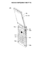
図1,2は、実施形態の携帯電話機の外観を示す図である。図1,2に示すように、携帯電話機100は、表示側筐体106と操作側筐体150とを備える。表示側筐体106と操作側筐体150は、ヒンジ構造152を介して互いに回転可能に連結されている。図1は、表示側筐体106及び操作側筐体150が互いに開いた状態を図示している。また、図2は、表示側筐体106及び操作側筐体150が互いに閉じた状態を図示している。図1,2に示すように、携帯電話機100は、表示側筐体106と操作側筐体150による折りたたみ式の携帯電話機である。
1 and 2 are views showing the appearance of the mobile phone according to the embodiment. As shown in FIGS. 1 and 2, the
また、図1に示すように、表示側筐体106は、表示側筐体106と操作側筐体150とを閉じた状態で対向する面に、タッチパネル式の表示部107を備える。また、操作側筐体150は、表示側筐体106と操作側筐体150とを閉じた状態で表示部107に対向する対向面151を備える。また、操作側筐体150は、対向面151に、各種操作を行うための複数のキー154と、4つの突起156a〜156dとを備える。突起156a〜156dはそれぞれ、表示側筐体106を折りたたんだ状態で、表示部107の四隅に当接する位置に設けられる。
In addition, as shown in FIG. 1, the display-
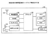
図3は、実施形態の携帯電話機のハードウェア構成を示す図である。図3に示すように、本実施形態の携帯電話機100は、アンテナ102、無線通信部104、表示部107、マイク108、スピーカ110、及び音声入出力部112を備える。また、携帯電話機100は、メモリ130、SD(Secure Digital)カード挿入スロット135、およびプロセッサ140を備える。SDカード挿入スロット135には、SDカード136が挿入される。
FIG. 3 is a diagram illustrating a hardware configuration of the mobile phone according to the embodiment. As shown in FIG. 3, the
無線通信部104は、アンテナ102を介して音声や文字などの各種データの無線通信を行う。また、表示部107には、文字や画像などの各種情報を表示するとともに、ユーザの各種操作の入力を受け付けるタッチパネル109が併設されている。
The wireless communication unit 104 performs wireless communication of various data such as voice and characters via the
また、音声入出力部112は、マイク108を介して音声を入力するとともにスピーカ110を介して音声を出力する入出力インターフェースである。
The voice input / output unit 112 is an input / output interface that inputs voice through the
メモリ130は、携帯電話機100の各種機能を実行するためのデータを格納するROM(Read Only Memory)132と、各種機能を実行するための各種プログラムを格納するRAM(Random Access Memory)134とを有する。
The memory 130 includes a ROM (Read Only Memory) 132 that stores data for executing various functions of the
プロセッサ140は、ROM132又はRAM134に格納された各種プログラムを実行するCPU(Central Processing Unit)等の演算処理部である。プロセッサ140は、ROM132又はRAM134に格納された各種プログラムを実行することにより、上述した無線通信部104、表示部107、タッチパネル109、及び音声入出力部112を制御する。なお、プロセッサ140で実行されるプログラムは、ROM132又はRAM134に格納されるだけではなく、CD(Compact Disc)−ROMやメモリ媒体等の頒布できる記憶媒体に記録しておき、記憶媒体から読み出して実行することができる。また、ネットワークを介して接続されたサーバにプログラムを格納し、サーバ上でプログラムが動作するようにしておいて、ネットワークを介して接続される携帯電話機100からの要求に応じてサービスを要求元の携帯電話機100に提供することもできる。
The
図4は、実施形態の携帯電話機の機能ブロックを示す図である。図4に示すように、携帯電話機100は、プロセッサ140がROM132又はRAM134から各種プログラムを読み出して実行することによって実現される機能ブロックとして、開閉検出部161、タイマー制御部162及び入力検出部164を備える。また、携帯電話機100は、プロセッサ140がROM132又はRAM134から各種プログラムを読み出して実行することによって実現される機能ブロックとして、キャリブレーション制御部166及び補正値記憶部168を備える。
FIG. 4 is a diagram illustrating functional blocks of the mobile phone according to the embodiment. As shown in FIG. 4, the
開閉検出部161は、表示側筐体106と操作側筐体150とが互いに折りたたまれたことを検出する。開閉検出部161は、例えば、表示側筐体106に設けられた磁石からの磁束密度を、操作側筐体150に設けられたホールIC(Integrated Circuit)で検出し、検出した磁束密度の大きさに基づいて表示側筐体106と操作側筐体150との開閉状態を検出する。開閉検出部161は、例えば、ホールICで検出された磁束密度が予め設定された閾値より大きくなったら、表示側筐体106と操作側筐体150とが互いに折りたたまれたことを検出する。
The open / close detection unit 161 detects that the display-
タイマー制御部162は、開閉検出部161によって表示側筐体106と操作側筐体150とが互いに折りたたまれてからの経過時間を計測する。
The timer control unit 162 measures an elapsed time since the display-
入力検出部164は、タッチパネル109に物体(例えばユーザの指や突起156a〜156d)が当接したら、物体が当接した位置に応じた入力信号を検出する。入力検出部164は、例えば、物体が当接したタッチパネル109の位置に応じて2つの電圧値を検出する。また、入力検出部164は、例えば、検出された2つの電圧値に基づいて、タッチパネル109上の物体が当接した2次元の位置座標を求める。入力検出部164は、例えば、予め2つの電圧値に対応する2次元の位置座標が格納されたテーブルを用いるか、又は検出された2つの電圧値に応じて2次元の位置座標が算出される座標算出式を用いることにより、タッチパネル109上の物体が当接した位置座標を求める。入力検出部164は、タッチパネル109に突起156a〜156dが当接したら、突起156a〜156dごとに、タッチパネル109上の突起156a〜156dが当接した位置座標を求める。
When an object (for example, a user's finger or
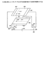
図5は、入力検出部によってタッチパネルの打点位置を検出する処理の概要を示す図である。図5に示すように、タッチパネル109は、対向する2枚の抵抗膜200,300を備える。また、抵抗膜200は、対向する2辺にそれぞれ正電極202及び負電極204が設けられる。また、抵抗膜300は、正電極202及び負電極204を結ぶ方向に直交する方向の対向する2辺にそれぞれ正電極302及び負電極304が設けられる。
FIG. 5 is a diagram showing an outline of processing for detecting the hit point position of the touch panel by the input detection unit. As shown in FIG. 5, the touch panel 109 includes two opposing
正電極202は端子206に接続され、正電極302は端子306に接続される。負電極204は端子208に接続され負電極304は端子308に接続される。一方電源400は、正電極側が端子402に接続され負電極側が端子404に接続される。端子402に設けられたスイッチ406は、端子206と端子306のいずれか一方に接続可能に設けられる。一方、端子404に設けられたスイッチ408は、端子208と端子308のいずれか一方に接続可能に設けられる。
入力検出部164は、スイッチ406を端子206に接続する場合には、スイッチ408を端子208に接続する。一方、入力検出部164は、スイッチ406を端子306に接続する場合には、スイッチ408を端子308に接続する。つまり、入力検出部164は、抵抗膜200に電圧を印加している際には、抵抗膜300には電圧を印加せず、抵抗膜300に電圧を印加している際には、抵抗膜200には電圧を印加しない。
The input detection unit 164 connects the
仮に、抵抗膜200の押圧点210が物体によって押圧されたとする。すると、抵抗膜200が撓んで抵抗膜300に接触する。押圧点210と接触する抵抗膜300上の点を押圧点310とする。入力検出部164は、抵抗膜200と抵抗膜300とが接触した状態で、スイッチ406を端子206に接続し、スイッチ408を端子208に接続することにより、抵抗膜200に電圧を印加する。すると抵抗膜200の正電極202から負電極204へ電位勾配が発生し、例えばライン212には同電位の電圧が印加され、押圧点210の電圧が押圧点310に現れる。この状態で、入力検出部164は、例えば端子308の電位を測定することにより、押圧点310の電位を求める。
Suppose that the
次に、入力検出部164は、抵抗膜200と抵抗膜300とが接触した状態のままでで、スイッチ406及びスイッチ408を切り替える。つまり、入力検出部164は、スイッチ406を端子306に接続しスイッチ408を端子308に接続することにより、抵抗膜300に電圧を印加する。すると抵抗膜300の正電極302から負電極304へ電位勾配が発生し、例えばライン312には同電位の電圧が印加され、押圧点310の電圧が押圧点210に現れる。この状態で、入力検出部164は、例えば端子208の電位を測定することにより、押圧点210の電位を求める。
Next, the input detection unit 164 switches the
そして、入力検出部164は、抵抗膜200に電圧を印加した状態で求められた押圧点310の電位と、抵抗膜300に電圧を印加した状態で求められた押圧点210の電位に基づいて、タッチパネル109における物体の当接する位置座標を検出する。
And the input detection part 164 is based on the electric potential of the
図4の説明に戻って、キャリブレーション制御部166は、入力検出部164によって検出された入力信号に基づいて、タッチパネル109の入力信号の較正を実行する。例えば、キャリブレーション制御部166は、タイマー制御部162によって計測された経過時間が予め設定された時間を越えたら、入力検出部164によって検出された入力信号に基づいて、タッチパネル109の入力信号の較正(キャリブレーション)を実行する。なお、タイマー制御部162によって計測された経過時間の閾値となる設定時間は、初期値に固定してもよいし、ユーザの操作によって任意の値に設定することもできる。
Returning to the description of FIG. 4, the
また、例えば、キャリブレーション制御部166は、開閉検出部161によって表示側筐体106と操作側筐体150とが折りたたまれたと検出された状態で予め設定された時刻になったら、入力検出部164によって検出された入力信号に基づいて、タッチパネル109の入力信号の較正(キャリブレーション)を実行する。なお、キャリブレーションを実行する時刻は、ユーザの操作によって任意に設定することができる。
In addition, for example, the
また、キャリブレーション制御部166は、入力検出部164によって検出された当接位置座標と、突起156a〜突起156dの当接位置に応じて予め設定された基準位置座標とに基づいて、タッチパネル109の入力信号の較正を実行する。例えば、キャリブレーション制御部166は、突起156a〜突起156dごとに、入力検出部164によって検出された2次元の当接位置座標と、予め設定された2次元の基準位置座標との各次元の差分を求め、この差分を補正値として求める。補正値は、例えばタッチパネル109の表示面上の直交2軸をx軸,y軸とすると、(x軸方向:−2,y軸方向:−3)などのように求められる。キャリブレーション制御部166は、突起156a〜突起156dごとに求められた補正値を、補正値記憶部168に格納する。
Further, the
なお、本実施形態では、4つの突起156a〜突起156dを、矩形のタッチパネル109の4隅に当接するように設ける例を示したが、これには限られない。例えば、突起156aと156dの組み合わせ又は突起156bと156cの組み合わせのように、矩形のタッチパネル109の対角線上の2隅に当接するように2つの突起を設けることもできる。
In the present embodiment, the four
補正値記憶部168は、キャリブレーション制御部166によって求められた座標の補正値が格納される記憶部である。なお、補正値記憶部168は、例えばメモリ130の内部に設けられるデータの記憶部である。
The correction value storage unit 168 is a storage unit that stores correction values of coordinates obtained by the
なお、入力検出部164は、キャリブレーション処理を実行する際には、実際に検出された物体の当接位置座標をキャリブレーション制御部166に出力する。一方、入力検出部164は、キャリブレーション処理の実行時以外は、補正値記憶部168に補正値が格納されている場合には、実際に検出された物体の当接位置座標を、補正値記憶部168に格納された補正値によって補正する。入力検出部164は、例えば、突起156a〜突起156dごとに補正値が補正値記憶部168に格納されている場合には、いずれかの補正値を選択して、実際に検出された物体の当接位置座標の補正用に用いることができる。例えば、入力検出部164は、突起156a〜突起156dに対応する基準位置座標の中から、実際に検出された物体の当接位置座標と最も距離が近い基準位置座標を選択する。そして、入力検出部164は、選択した基準位置座標に対応する突起の補正値を、実際に検出された物体の当接位置座標の補正用に用いることができる。
Note that the input detection unit 164 outputs the actually detected contact position coordinates of the object to the
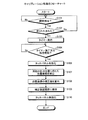
次に、キャリブレーション処理の流れを説明する。図6は、キャリブレーション処理のフローチャートである。図6に示すように、まず、開閉検出部161は、表示側筐体106と操作側筐体150との開閉が検出されたか否かを判定する(ステップS101)。開閉検出部161は、表示側筐体106と操作側筐体150との開閉が検出されるまで、ステップS101を繰り返す。
Next, the flow of calibration processing will be described. FIG. 6 is a flowchart of the calibration process. As shown in FIG. 6, first, the open / close detection unit 161 determines whether opening / closing between the display-
開閉検出部161は、表示側筐体106と操作側筐体150との開閉が検出されたと判定されたら(ステップS101でYes)、表示側筐体106と操作側筐体150とが折りたたまれたか否かを判定する(ステップS102)。
If it is determined that opening / closing between the display-
タイマー制御部162は、表示側筐体106と操作側筐体150とが折りたたまれたと判定されたら(ステップS102でYes)、タイマーを発行する(ステップS103)。続いて、キャリブレーション制御部166は、タイマー制御部162によってタイマーが発行されてから予め設定された時間が経過してタイマーが満了したか、又は現在時刻が予め設定された指定時刻であるか否かを判定する(ステップS104)。
When it is determined that the display-
キャリブレーション制御部166は、タイマー制御部162によってタイマーが発行されてから予め設定された時間が経過してタイマーが満了したか、又は現在時刻が予め設定された指定時刻であると判定されたら(ステップS104でYes)、キャリブレーション処理を開始する。キャリブレーション制御部166は、タイマー制御部162によってタイマーが発行されてから予め設定された時間が経過してタイマーが満了したか、又は現在時刻が予め設定された指定時刻であると判定されるまで、ステップS104の判定を繰り返す(ステップS104でNo)。
The
キャリブレーション制御部166は、タッチパネル109を有効にする(ステップS106)。続いて、入力検出部164は、突起156a〜156dごとに、タッチパネル109の突起156の打点位置に応じて2次元の位置座標を検出する(ステップS107)。キャリブレーション制御部166は、入力検出部164によって検出された位置座標と、突起156a〜156dの当接位置に応じて予め設定された基準位置座標とに基づいて、位置座標の補正値を算出する(ステップS108)。キャリブレーション制御部166は、算出された補正値を、補正値記憶部168へ保存する(ステップS109)。キャリブレーション制御部166は、タッチパネル109を無効にして(ステップS110)、処理を終了する。
The
一方、キャリブレーション制御部166は、表示側筐体106と操作側筐体150とが折りたたまれていないと判定されたら(ステップS102でNo)、S101に遷移し、次の開閉検出に向けて待機する。
On the other hand, if it is determined that the display-
以上、本実施形態の携帯電話機100は、任意のタイミングで自動的に正確なタッチパネルのキャリブレーション処理を実行することができる。すなわち、本実施形態の携帯電話機100は、タッチパネル109に対向する対向部に、タッチパネル109に当接する突起を設けることにより、ユーザが指定位置を押圧することなく、任意のタイミングで自動的に正確なタッチパネル109のキャリブレーション処理を実行することができる。
As described above, the
また、本実施形態のような折りたたみ形状の携帯電話機100は、携帯電話機100を利用しない場合には折りたたんで放置するケースが多い。そこで、本実施形態の携帯電話機100は、表示側筐体106と操作側筐体150とが折りたたまれたことが検出されてから、予め設定された時間が経過したら、キャリブレーション処理を実行する。よって、本実施形態の携帯電話機100によれば、携帯電話機100を使用していないと推測される時間を利用してタッチパネル109のキャリブレーションを実行することができる。
Further, the folding
また、本実施形態の携帯電話機100は、表示側筐体106と操作側筐体150とが折りたたまれた状態で予め設定された時刻になったら、タッチパネル109のキャリブレーションを実行する。よって、本実施形態の携帯電話機100によれば、例えば就寝中の時間など携帯電話機100を使用していない時間を利用してタッチパネル109のキャリブレーションを実行することができる。
In addition, the
なお、本実施形態は、主に携帯電話機及びキャリブレーション制御方法を中心に説明したが、これに限らず、あらかじめ用意されたキャリブレーション制御プログラムをコンピュータで実行することによって、上述の実施形態と同様の機能を実現することができる。すなわち、キャリブレーション制御制御プログラムが処理を実行させる電子装置は、物体が当接する位置に応じた操作入力を受け付けるタッチパネルを備えた第1の筐体と、前記第1の筐体に可動連結され、前記タッチパネルと対向する対向部を備えた第2の筐体とを備える。また、キャリブレーション制御制御プログラムが処理を実行させる電子装置は、前記対向部に設けられ、前記対向部が前記タッチパネルに対向した状態で前記タッチパネルに当接する突起を備える。キャリブレーション制御制御プログラムは、このような電子装置に、前記突起が当接する前記タッチパネルの位置に応じた入力信号を検出する処理を実行させる。また、キャリブレーション制御制御プログラムは、このような電子装置に、前記検出された入力信号に基づいて、前記タッチパネルの入力信号の較正を実行する処理を実行させる。なお、キャリブレーション制御プログラムは、インターネットなどの通信ネットワークを介してコンピュータに配布することができる。また、キャリブレーション制御プログラムは、電子装置に設けられたメモリ、ハードディスク、その他のコンピュータで読み取り可能な記録媒体に記録され、コンピュータによって記録媒体から読み出されることによって実行することもできる。 The present embodiment has been described mainly with respect to the mobile phone and the calibration control method. However, the present embodiment is not limited to this, and by executing a calibration control program prepared in advance by a computer, the same as the above-described embodiment. The function can be realized. That is, an electronic device that causes the calibration control control program to execute processing is movably connected to a first housing having a touch panel that receives an operation input according to a position where an object abuts, and the first housing, A second housing having a facing portion facing the touch panel. In addition, an electronic device that causes the calibration control control program to execute processing includes a protrusion that is provided in the facing portion and that contacts the touch panel in a state where the facing portion faces the touch panel. The calibration control control program causes such an electronic device to execute a process of detecting an input signal corresponding to the position of the touch panel with which the protrusion comes into contact. Further, the calibration control control program causes such an electronic apparatus to execute a process of calibrating the input signal of the touch panel based on the detected input signal. Note that the calibration control program can be distributed to computers via a communication network such as the Internet. The calibration control program can also be executed by being recorded on a memory, a hard disk, or other computer-readable recording medium provided in the electronic apparatus, and being read from the recording medium by the computer.
100 携帯電話機
106 表示側筐体
107 表示部
109 タッチパネル
150 操作側筐体
151 対向面
152 ヒンジ構造
156a〜156d 突起
161 開閉検出部
162 タイマー制御部
164 入力検出部
166 キャリブレーション制御部
168 補正値記憶部
200,300 抵抗膜
DESCRIPTION OF
Claims (5)
前記第1の筐体に可動連結され、前記タッチパネルと対向する対向部を備えた第2の筐体と、
前記対向部に設けられ、前記対向部が前記タッチパネルに対向した状態で前記タッチパネルに当接する突起と、
前記突起が当接する前記タッチパネルの位置に応じた入力信号を検出する入力検出部と、
前記入力検出部によって検出された入力信号に基づいて、前記タッチパネルの入力信号の較正を実行するキャリブレーション制御部と、
を備えることを特徴とする電子装置。 A first housing including a touch panel that receives an operation input according to a position where the object comes into contact;
A second housing that is movably coupled to the first housing and has a facing portion facing the touch panel;
Protrusions that are provided in the facing portion and that come into contact with the touch panel with the facing portion facing the touch panel;
An input detection unit that detects an input signal according to the position of the touch panel with which the protrusion abuts;
A calibration control unit that calibrates the input signal of the touch panel based on the input signal detected by the input detection unit;
An electronic device comprising:
前記第1の筐体と前記第2の筐体とが折りたたまれたことを検出する開閉検出部と、
前記開閉検出部によって前記第1の筐体と前記第2の筐体とが折りたたまれたと検出されてからの経過時間を計測するタイマー制御部とをさらに備え、
前記キャリブレーション制御部は、前記タイマー制御部によって計測された経過時間が予め設定された時間を超えたら、前記入力検出部によって検出された入力信号に基づいて、前記タッチパネルの入力信号の較正を実行する
ことを特徴とする請求項1に記載の電子装置。 The electronic device has a folding structure in which the first housing and the second housing are connected to each other through a hinge structure so as to freely rotate.
An open / close detection unit for detecting that the first casing and the second casing are folded;
A timer control unit that measures an elapsed time since it is detected that the first housing and the second housing are folded by the open / close detection unit;
When the elapsed time measured by the timer control unit exceeds a preset time, the calibration control unit calibrates the input signal of the touch panel based on the input signal detected by the input detection unit. The electronic device according to claim 1, wherein:
前記第1の筐体と前記第2の筐体とが折りたたまれたことを検出する開閉検出部を
さらに備え、
前記キャリブレーション制御部は、前記開閉検出部によって前記第1の筐体と前記第2の筐体とが折りたたまれたと検出された状態で予め設定された時刻になったら、前記入力検出部によって検出された入力信号に基づいて、前記タッチパネルの入力信号の較正を実行する
ことを特徴とする請求項1に記載の電子装置。 The electronic device has a folding structure in which the first housing and the second housing are connected to each other through a hinge structure so as to freely rotate.
An opening / closing detector for detecting that the first casing and the second casing are folded;
The calibration control unit is detected by the input detection unit when a preset time is reached in a state where the first and second cases are detected to be folded by the open / close detection unit. The electronic device according to claim 1, wherein calibration of the input signal of the touch panel is executed based on the input signal that has been input.
前記入力検出部は、前記物体の当接圧力によって前記2枚の抵抗膜が接触した状態で、前記2枚の抵抗膜に順次電圧を印加することにより前記2枚の抵抗膜それぞれの接触点における電圧値を検出し、検出された電圧値に応じて前記物体の当接位置座標を検出し、
前記キャリブレーション制御部は、前記入力検出部によって検出された当接位置座標と、前記突起の当接位置に応じて予め設定された基準位置座標とに基づいて、前記タッチパネルの入力信号の較正を実行する
ことを特徴とする請求項1に記載の電子装置。 The touch panel is a resistance pressure-sensitive touch panel including two opposing resistance films,
The input detection unit applies voltage sequentially to the two resistive films in a state in which the two resistive films are in contact with each other due to the contact pressure of the object, so that the input detection unit at each contact point of the two resistive films. Detecting the voltage value, detecting the contact position coordinates of the object according to the detected voltage value,
The calibration control unit calibrates an input signal of the touch panel based on a contact position coordinate detected by the input detection unit and a reference position coordinate set in advance according to the contact position of the protrusion. The electronic device according to claim 1, wherein the electronic device is executed.
前記突起が当接する前記タッチパネルの位置に応じた入力信号を検出し、
前記検出された入力信号に基づいて、前記タッチパネルの入力信号の較正を実行する
処理を実行させることを特徴とするキャリブレーション制御プログラム。 A first housing having a touch panel that accepts an operation input according to a position where the object comes into contact; and a second housing that is movably connected to the first housing and has a facing portion facing the touch panel. An electronic device provided with a protrusion that is provided in the facing portion and that comes into contact with the touch panel in a state where the facing portion faces the touch panel.
Detecting an input signal corresponding to the position of the touch panel with which the protrusion abuts,
A calibration control program for executing a process of calibrating an input signal of the touch panel based on the detected input signal.
Priority Applications (1)
| Application Number | Priority Date | Filing Date | Title |
|---|---|---|---|
| JP2011071164A JP2012203887A (en) | 2011-03-28 | 2011-03-28 | Electronic device and calibration control program |
Applications Claiming Priority (1)
| Application Number | Priority Date | Filing Date | Title |
|---|---|---|---|
| JP2011071164A JP2012203887A (en) | 2011-03-28 | 2011-03-28 | Electronic device and calibration control program |
Publications (1)
| Publication Number | Publication Date |
|---|---|
| JP2012203887A true JP2012203887A (en) | 2012-10-22 |
Family
ID=47184770
Family Applications (1)
| Application Number | Title | Priority Date | Filing Date |
|---|---|---|---|
| JP2011071164A Pending JP2012203887A (en) | 2011-03-28 | 2011-03-28 | Electronic device and calibration control program |
Country Status (1)
| Country | Link |
|---|---|
| JP (1) | JP2012203887A (en) |
Cited By (2)
| Publication number | Priority date | Publication date | Assignee | Title |
|---|---|---|---|---|
| JP2015077360A (en) * | 2013-10-18 | 2015-04-23 | 株式会社オーイズミ | Game medium counting machine |
| CN106459325A (en) * | 2014-06-25 | 2017-02-22 | 大日精化工业株式会社 | A-B block co-polymer, A-B block co-polymer production method, resin treatment pigment composition, resin treatment pigment composition production method, pigment dispersion, and pigment dispersion solution |
Citations (11)
| Publication number | Priority date | Publication date | Assignee | Title |
|---|---|---|---|---|
| JPH06175768A (en) * | 1992-12-04 | 1994-06-24 | Casio Comput Co Ltd | Coordinate input device |
| JP2001265512A (en) * | 2000-03-15 | 2001-09-28 | Fujitsu Ten Ltd | Resistance film type touch panel device |
| JP2003280820A (en) * | 2002-03-22 | 2003-10-02 | Fujitsu Component Ltd | Input device and electronic device |
| JP2004021471A (en) * | 2002-06-14 | 2004-01-22 | Mitsubishi Electric Corp | Fingerprint collating device |
| JP2006074394A (en) * | 2004-09-01 | 2006-03-16 | Canon Inc | Image processing system and density compensation schedule managing method |
| JP2007035076A (en) * | 2003-05-19 | 2007-02-08 | Eit:Kk | Position detection apparatus using area image sensor |
| WO2008108275A1 (en) * | 2007-03-07 | 2008-09-12 | Nec Corporation | Display terminal with touch panel function and calibration method |
| JP2009145978A (en) * | 2007-12-11 | 2009-07-02 | Canon Inc | Calibration method and device |
| JP2010170310A (en) * | 2009-01-22 | 2010-08-05 | Nikon Corp | Terminal device |
| JP2011022788A (en) * | 2009-07-15 | 2011-02-03 | Digital Electronics Corp | Touch position detection device |
| JP2011221582A (en) * | 2010-04-02 | 2011-11-04 | Canon Inc | Information processor, calibration method thereof, program and storage medium |
-
2011
- 2011-03-28 JP JP2011071164A patent/JP2012203887A/en active Pending
Patent Citations (11)
| Publication number | Priority date | Publication date | Assignee | Title |
|---|---|---|---|---|
| JPH06175768A (en) * | 1992-12-04 | 1994-06-24 | Casio Comput Co Ltd | Coordinate input device |
| JP2001265512A (en) * | 2000-03-15 | 2001-09-28 | Fujitsu Ten Ltd | Resistance film type touch panel device |
| JP2003280820A (en) * | 2002-03-22 | 2003-10-02 | Fujitsu Component Ltd | Input device and electronic device |
| JP2004021471A (en) * | 2002-06-14 | 2004-01-22 | Mitsubishi Electric Corp | Fingerprint collating device |
| JP2007035076A (en) * | 2003-05-19 | 2007-02-08 | Eit:Kk | Position detection apparatus using area image sensor |
| JP2006074394A (en) * | 2004-09-01 | 2006-03-16 | Canon Inc | Image processing system and density compensation schedule managing method |
| WO2008108275A1 (en) * | 2007-03-07 | 2008-09-12 | Nec Corporation | Display terminal with touch panel function and calibration method |
| JP2009145978A (en) * | 2007-12-11 | 2009-07-02 | Canon Inc | Calibration method and device |
| JP2010170310A (en) * | 2009-01-22 | 2010-08-05 | Nikon Corp | Terminal device |
| JP2011022788A (en) * | 2009-07-15 | 2011-02-03 | Digital Electronics Corp | Touch position detection device |
| JP2011221582A (en) * | 2010-04-02 | 2011-11-04 | Canon Inc | Information processor, calibration method thereof, program and storage medium |
Cited By (2)
| Publication number | Priority date | Publication date | Assignee | Title |
|---|---|---|---|---|
| JP2015077360A (en) * | 2013-10-18 | 2015-04-23 | 株式会社オーイズミ | Game medium counting machine |
| CN106459325A (en) * | 2014-06-25 | 2017-02-22 | 大日精化工业株式会社 | A-B block co-polymer, A-B block co-polymer production method, resin treatment pigment composition, resin treatment pigment composition production method, pigment dispersion, and pigment dispersion solution |
Similar Documents
| Publication | Publication Date | Title |
|---|---|---|
| US8294688B2 (en) | Resistive touch screen apparatus, a method and a computer program | |
| US8803818B2 (en) | Input apparatus, input determining method, and storage medium storing input program | |
| US10444910B2 (en) | Electronic device and method of processing user actuation of a touch-sensitive input surface | |
| JP2019516187A (en) | Display interface control method, device and terminal for preventing erroneous operation | |
| JP2020500362A (en) | Method for preventing erroneous touch and terminal | |
| US20110157083A1 (en) | Resistive touch apparatus | |
| WO2017161803A1 (en) | Method and terminal for adjusting settings | |
| US9052741B2 (en) | Method in a mobile terminal for judging a contact between an operating member and touchpad | |
| EP2466420B1 (en) | Portable electronic device having a sensor arrangement for gesture recognition | |
| JP2018073210A (en) | Electronic equipment, display device and operation control program | |
| US20170212659A1 (en) | Method and apparatus for selecting link entities in touch screen based web browser environment | |
| KR20150081657A (en) | Mobile terminal and method for control thereof | |
| WO2012016440A1 (en) | Method, apparatus and terminal for locating touch point of touch screen | |
| JP6089906B2 (en) | Input device, input program, and input method | |
| JP2012203887A (en) | Electronic device and calibration control program | |
| US8842087B2 (en) | Method for processing touch signal and electronic device using the same | |
| TWI596535B (en) | Touch panel apparatus, control apparatus, and control method | |
| EP2816448B1 (en) | Information processing device | |
| WO2012159323A1 (en) | Method for simulating key input using capacitive stylus, capacitive stylus and terminal | |
| US9342203B2 (en) | Input apparatus and input method | |
| WO2013190857A1 (en) | Processing device, sensitivity adjustment method and program | |
| JP6504937B2 (en) | INPUT DETERMINATION DEVICE, CONTROL PROGRAM, ELECTRONIC DEVICE, AND INPUT THRESHOLD CALIBRATING METHOD OF INPUT DETERMINATION DEVICE | |
| CN110568966A (en) | Display panel, mobile terminal and method for adjusting display interface of mobile terminal | |
| JP2016148643A (en) | Electronic apparatus and calibration method | |
| JP6673407B2 (en) | Electronics |
Legal Events
| Date | Code | Title | Description |
|---|---|---|---|
| A621 | Written request for application examination |
Free format text: JAPANESE INTERMEDIATE CODE: A621 Effective date: 20140108 |
|
| A977 | Report on retrieval |
Free format text: JAPANESE INTERMEDIATE CODE: A971007 Effective date: 20140829 |
|
| A131 | Notification of reasons for refusal |
Free format text: JAPANESE INTERMEDIATE CODE: A131 Effective date: 20140902 |
|
| A02 | Decision of refusal |
Free format text: JAPANESE INTERMEDIATE CODE: A02 Effective date: 20150106 |