JP2012203230A - Display device - Google Patents
Display device Download PDFInfo
- Publication number
- JP2012203230A JP2012203230A JP2011068153A JP2011068153A JP2012203230A JP 2012203230 A JP2012203230 A JP 2012203230A JP 2011068153 A JP2011068153 A JP 2011068153A JP 2011068153 A JP2011068153 A JP 2011068153A JP 2012203230 A JP2012203230 A JP 2012203230A
- Authority
- JP
- Japan
- Prior art keywords
- pixel
- pixels
- display
- distance
- viewpoint
- Prior art date
- Legal status (The legal status is an assumption and is not a legal conclusion. Google has not performed a legal analysis and makes no representation as to the accuracy of the status listed.)
- Granted
Links
- 238000001514 detection method Methods 0.000 claims abstract description 10
- 238000000926 separation method Methods 0.000 claims description 14
- 230000004888 barrier function Effects 0.000 description 32
- 238000000034 method Methods 0.000 description 30
- 238000013461 design Methods 0.000 description 10
- 239000000758 substrate Substances 0.000 description 10
- 238000010586 diagram Methods 0.000 description 9
- 239000011521 glass Substances 0.000 description 7
- 239000004973 liquid crystal related substance Substances 0.000 description 6
- 238000003384 imaging method Methods 0.000 description 4
- 238000007796 conventional method Methods 0.000 description 2
- 238000012986 modification Methods 0.000 description 2
- 230000004048 modification Effects 0.000 description 2
- 238000005498 polishing Methods 0.000 description 2
- 239000012790 adhesive layer Substances 0.000 description 1
- 239000003086 colorant Substances 0.000 description 1
- 239000002131 composite material Substances 0.000 description 1
- 230000000694 effects Effects 0.000 description 1
- 238000004519 manufacturing process Methods 0.000 description 1
- 239000000463 material Substances 0.000 description 1
- 239000002184 metal Substances 0.000 description 1
- 238000012545 processing Methods 0.000 description 1
- 239000010409 thin film Substances 0.000 description 1
Images


Classifications
-
- G—PHYSICS
- G02—OPTICS
- G02B—OPTICAL ELEMENTS, SYSTEMS OR APPARATUS
- G02B30/00—Optical systems or apparatus for producing three-dimensional [3D] effects, e.g. stereoscopic images
-
- H—ELECTRICITY
- H04—ELECTRIC COMMUNICATION TECHNIQUE
- H04N—PICTORIAL COMMUNICATION, e.g. TELEVISION
- H04N13/00—Stereoscopic video systems; Multi-view video systems; Details thereof
- H04N13/30—Image reproducers
- H04N13/302—Image reproducers for viewing without the aid of special glasses, i.e. using autostereoscopic displays
- H04N13/31—Image reproducers for viewing without the aid of special glasses, i.e. using autostereoscopic displays using parallax barriers
-
- G—PHYSICS
- G02—OPTICS
- G02B—OPTICAL ELEMENTS, SYSTEMS OR APPARATUS
- G02B30/00—Optical systems or apparatus for producing three-dimensional [3D] effects, e.g. stereoscopic images
- G02B30/20—Optical systems or apparatus for producing three-dimensional [3D] effects, e.g. stereoscopic images by providing first and second parallax images to an observer's left and right eyes
- G02B30/26—Optical systems or apparatus for producing three-dimensional [3D] effects, e.g. stereoscopic images by providing first and second parallax images to an observer's left and right eyes of the autostereoscopic type
- G02B30/27—Optical systems or apparatus for producing three-dimensional [3D] effects, e.g. stereoscopic images by providing first and second parallax images to an observer's left and right eyes of the autostereoscopic type involving lenticular arrays
-
- G—PHYSICS
- G02—OPTICS
- G02B—OPTICAL ELEMENTS, SYSTEMS OR APPARATUS
- G02B30/00—Optical systems or apparatus for producing three-dimensional [3D] effects, e.g. stereoscopic images
- G02B30/20—Optical systems or apparatus for producing three-dimensional [3D] effects, e.g. stereoscopic images by providing first and second parallax images to an observer's left and right eyes
- G02B30/26—Optical systems or apparatus for producing three-dimensional [3D] effects, e.g. stereoscopic images by providing first and second parallax images to an observer's left and right eyes of the autostereoscopic type
- G02B30/30—Optical systems or apparatus for producing three-dimensional [3D] effects, e.g. stereoscopic images by providing first and second parallax images to an observer's left and right eyes of the autostereoscopic type involving parallax barriers
-
- G—PHYSICS
- G09—EDUCATION; CRYPTOGRAPHY; DISPLAY; ADVERTISING; SEALS
- G09G—ARRANGEMENTS OR CIRCUITS FOR CONTROL OF INDICATING DEVICES USING STATIC MEANS TO PRESENT VARIABLE INFORMATION
- G09G3/00—Control arrangements or circuits, of interest only in connection with visual indicators other than cathode-ray tubes
- G09G3/20—Control arrangements or circuits, of interest only in connection with visual indicators other than cathode-ray tubes for presentation of an assembly of a number of characters, e.g. a page, by composing the assembly by combination of individual elements arranged in a matrix no fixed position being assigned to or needed to be assigned to the individual characters or partial characters
-
- H—ELECTRICITY
- H04—ELECTRIC COMMUNICATION TECHNIQUE
- H04N—PICTORIAL COMMUNICATION, e.g. TELEVISION
- H04N13/00—Stereoscopic video systems; Multi-view video systems; Details thereof
- H04N13/30—Image reproducers
- H04N13/366—Image reproducers using viewer tracking
- H04N13/373—Image reproducers using viewer tracking for tracking forward-backward translational head movements, i.e. longitudinal movements
-
- H—ELECTRICITY
- H04—ELECTRIC COMMUNICATION TECHNIQUE
- H04N—PICTORIAL COMMUNICATION, e.g. TELEVISION
- H04N13/00—Stereoscopic video systems; Multi-view video systems; Details thereof
- H04N13/30—Image reproducers
- H04N13/366—Image reproducers using viewer tracking
- H04N13/376—Image reproducers using viewer tracking for tracking left-right translational head movements, i.e. lateral movements
-
- G—PHYSICS
- G02—OPTICS
- G02B—OPTICAL ELEMENTS, SYSTEMS OR APPARATUS
- G02B27/00—Optical systems or apparatus not provided for by any of the groups G02B1/00 - G02B26/00, G02B30/00
- G02B27/0093—Optical systems or apparatus not provided for by any of the groups G02B1/00 - G02B26/00, G02B30/00 with means for monitoring data relating to the user, e.g. head-tracking, eye-tracking
Abstract
Description
本開示は、パララックスバリア等の視差分離手段を用いて裸眼方式による立体表示を行う表示装置に関する。 The present disclosure relates to a display device that performs stereoscopic display by a naked-eye method using parallax separation means such as a parallax barrier.
立体表示を行う手法としては、立体視用の眼鏡を用いる眼鏡方式と、立体視用の特殊な眼鏡を用いることなく裸眼での立体視を可能にした裸眼方式とがある。眼鏡方式の代表的なものとしては、左眼用シャッタと右眼用シャッタとを有するシャッタめがねを用いるシャッタめがね方式がある。シャッタめがね方式では、2次元表示パネルに左眼用と右眼用の各視差画像をフレームシーケンシャルで高速で交互に表示する。そして、各視差画像の表示タイミングに合わせて左眼用シャッタと右眼用シャッタとを交互に切り換えることにより、観察者の左眼には左眼用視差画像、右眼には右眼用視差画像のみを入射させることで、立体視を可能にしている。 As a method for performing stereoscopic display, there are a spectacle method using stereoscopic glasses and a naked-eye method that enables stereoscopic viewing with the naked eye without using special glasses for stereoscopic viewing. A typical spectacle method is a shutter spectacle method using shutter glasses having a left eye shutter and a right eye shutter. In the shutter glasses method, left-eye and right-eye parallax images are alternately displayed at high speed in a frame sequential manner on a two-dimensional display panel. Then, by alternately switching the left-eye shutter and the right-eye shutter according to the display timing of each parallax image, the left-eye parallax image for the observer's left eye and the right-eye parallax image for the right eye By making only the light incident, stereoscopic viewing is possible.
一方、裸眼方式の代表的なものとしては、パララックスバリア方式とレンチキュラレンズ方式とがある。パララックスバリア方式やレンチキュラ方式の場合、2次元表示パネルに立体視用の視差画像(2視点の場合には右眼用視差画像と左眼用視差画像)を空間分割して表示し、その視差画像を視差分離手段によって水平方向に視差分離することで立体視が行われる。パララックスバリア方式の場合、視差分離手段としてスリット状の開口が設けられたパララックスバリアを用いる。レンチキュラ方式の場合、視差分離手段として、シリンドリカル状の分割レンズを複数並列配置したレンチキュラレンズが用いられる。 On the other hand, representative examples of the naked eye method include a parallax barrier method and a lenticular lens method. In the case of the parallax barrier method or the lenticular method, a parallax image for stereoscopic viewing (a parallax image for the right eye and a parallax image for the left eye in the case of two viewpoints) is spatially divided and displayed on the two-dimensional display panel. Stereoscopic viewing is performed by separating the image in the horizontal direction by the parallax separating means. In the case of the parallax barrier method, a parallax barrier provided with a slit-like opening is used as the parallax separation means. In the case of the lenticular method, a lenticular lens in which a plurality of cylindrical divided lenses are arranged in parallel is used as the parallax separation means.
しかしながら、視差分離手段を用いた裸眼方式では、観察者の視点位置が設計上の所定領域から外れると、正常な立体視ができないという問題がある。また、特許文献1には、設計上の適視距離を短くできるようにした表示装置に関する発明が開示されているが、適視距離を短くしすぎると、視差分離手段と画像を表示する表示部との間隔が短くなりすぎて製造が困難になる場合がある。
However, with the naked eye method using the parallax separation means, there is a problem that normal stereoscopic viewing cannot be performed if the viewpoint position of the observer deviates from a predetermined design area. Further,
本開示の目的は、視点位置に応じた最適な立体表示を行うことができるようにした表示装置を提供することにある。 An object of the present disclosure is to provide a display device capable of performing optimal stereoscopic display according to a viewpoint position.
本開示による表示装置は、第1〜第n(nは4以上の整数)の画素をそれぞれ複数有し、複数の視点画像を第1〜第nの各画素に割り当てて表示する表示部と、観察者の視点位置を検出する検出部と、観察者の視点位置に応じて、第1〜第nの画素に割り当てる複数の視点画像の数および第1〜第nの各画素と各視点画像との対応関係を変化させる表示制御部とを備えたものである。 The display device according to the present disclosure includes a plurality of first to n-th (n is an integer of 4 or more) pixels, a display unit that assigns and displays a plurality of viewpoint images to the first to n-th pixels, A detection unit for detecting the viewpoint position of the observer, the number of the plurality of viewpoint images to be assigned to the first to n-th pixels and the first to n-th pixels and the viewpoint images according to the viewpoint position of the observer; And a display control unit that changes the correspondence relationship.
本開示の表示装置では、観察者の視点位置に応じて、第1〜第nの画素に割り当てられる複数の視点画像の数および第1〜第nの各画素と各視点画像との対応関係を変化させる制御が行われる。 In the display device of the present disclosure, the number of the plurality of viewpoint images assigned to the first to nth pixels and the correspondence relationship between the first to nth pixels and each viewpoint image are determined according to the viewpoint position of the observer. Control to change is performed.
本開示の表示装置によれば、観察者の視点位置に応じて、第1〜第nの画素に割り当てる複数の視点画像の数および第1〜第nの各画素と各視点画像との対応関係を変化させるようにしたので、視点位置に応じた最適な立体表示を行うことができる。 According to the display device of the present disclosure, the number of the plurality of viewpoint images assigned to the first to n-th pixels and the correspondence relationship between the first to n-th pixels and each viewpoint image according to the viewpoint position of the observer. Therefore, it is possible to perform optimal stereoscopic display according to the viewpoint position.
以下、本開示の実施の形態について図面を参照して詳細に説明する。 Hereinafter, embodiments of the present disclosure will be described in detail with reference to the drawings.
[表示装置の全体構成]
図1は、本開示の一実施の形態に係る表示装置の一構成例を示している。この表示装置は、検出部1と、表示制御部4と、画像生成部5と、表示部6とを備えている。検出部1は、撮像部2と、視点位置判定部3とを有している。
[Overall configuration of display device]
FIG. 1 illustrates a configuration example of a display device according to an embodiment of the present disclosure. The display device includes a
表示部6は、液晶表示パネル、エレクトリックルミナンス方式の表示パネル、またはプラズマディスプレイ等の2次元表示ディスプレイで構成されている。表示部6の表示画面には、複数の画素が2次元的に配列されている。表示部6の表示画面には、この表示装置の立体表示方式に応じた画像表示がなされる。表示部6の複数の画素(またはサブピクセル)には、立体表示の第1〜第nの視点数に応じて第1〜第n(nは4以上の整数)の番号付けがなされる。
The
この表示装置は、裸眼方式による立体表示を行うものであり、その立体表示方式は、パララックスバリア方式やレンチキュラレンズ方式等の視差分離手段を用いた方式となっている。レンチキュラ方式の場合、視差分離手段として、例えばシリンドリカル状の分割レンズを複数並列配置したレンチキュラレンズが用いられる。表示部6には、複数の視点用の視差画像(視点画像)が1画面内に合成された視差合成画像が表示される。すなわち、複数の視点画像が空間分割されて表示される。この表示装置は、後述するように、観察者の視点位置に応じて表示部6に表示する視点画像の数を変化させるようになっている。例えば観察者の視点位置が第1の距離Z0/2(後述の図9等参照)にある場合には、複数の視点画像として、左眼用画像と右眼用画像との左右2視点の視差画像を表示するようになっている。また、例えば観察者の視点位置が、通常の適視距離である第2の距離Z0にある場合には、複数の視点画像として、多視点の視差画像、例えば第1〜第4の視点画像を表示するようになっている(後述の図2等参照)。
This display device performs stereoscopic display by the naked eye method, and the stereoscopic display method is a method using parallax separation means such as a parallax barrier method or a lenticular lens method. In the case of the lenticular method, for example, a lenticular lens in which a plurality of cylindrical divided lenses are arranged in parallel is used as the parallax separation means. The
以下、本実施の形態では、パララックスバリア方式の立体表示を行う場合を例に説明する。パララックスバリア方式の場合、例えば図2に示したように、視差分離手段としてバリア素子7が用いられる。バリア素子7は、光を透過する開口部8と、光を遮蔽する遮蔽部9とを備えている。バリア素子7は、固定式のパララックスバリアであっても良いし、可変式のパララックスバリアであっても良い。固定式のパララックスバリアの場合、例えば透明な平行平面板(基材)の表面に、薄膜状の金属などで開口部8および遮蔽部9となるパターンを形成したものを用いることができる。可変式のパララックスバリアとする場合、例えばバックライト方式の液晶表示素子による表示機能(光変調機能)を用いて、開口部8および遮蔽部9のパターンを選択的に形成することができる。なお、図2では、表示部6の表示面側にバリア素子7を配置した例を示しているが、表示部6の背面側にバリア素子7を配置する構成であっても良い、例えば表示部6としてバックライト方式の液晶表示パネルを用いる場合、液晶表示パネルの背面側で、バックライトと液晶表示パネルとの間にバリア素子7を配置すれば良い。
Hereinafter, in the present embodiment, a case where stereoscopic display using a parallax barrier method is performed will be described as an example. In the case of the parallax barrier method, for example, as shown in FIG. 2, the
撮像部2は、観察者を撮影するものである。視点位置判定部3は、撮像部2による撮影画像を解析することによって、観察者の視点位置(表示部6に対する視距離および表示面に平行な面内方向の位置)を判定するものである。検出部1による視点位置の検出には、例えばフェイストラッキング技術を用いることができる。なお、視距離は通常、表示部6の表示面から観察者の両眼の中心位置までの距離である。
The
表示制御部4は、検出部1で検出された観察者の視点位置に応じて、表示部6に表示する画像の制御を行うようになっている。表示制御部4は、後述するように、観察者の視点位置が表示部6に対して第1の距離Z0/2にある場合に、表示部6の各画素を複数の分割領域31(後述の図11等参照)ごとに表示制御し、各分割領域31ごとに第1〜第nの各画素と各視点画像(左眼用画像と右眼用画像)との対応関係を変化させるようになっている。表示制御部4はまた、後述するように、観察者の視点位置が第2の距離Z0にある場合に、複数の視点画像として第1〜第nの視点画像を画面全体において第1〜第nの各画素に割り当てるようになっている。
The
画像生成部5は、表示制御部4の制御に従って観察者の視点位置に応じた複数の視点画像を含む画像データを生成して表示部6に供給するようになっている。表示制御部4は、画像生成部5によって生成された画像データを表示部6に表示させる。
The
[通常の適視距離(第2の距離Z0)における立体表示の原理]
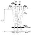
図3は、この表示装置において4視点の立体表示を行う場合の原理を示している。この図3の例による表示原理は、基本的に従来のパララックスバリア方式による4視点の立体表示の原理と同様である。表示部6の複数の画素(またはサブピクセル)には、4つの視点数に応じて第1〜第4の番号付けがなされている。表示制御部4は、複数の視点画像として第1〜第4の視点画像を、表示部6の画面全体において第1〜第4の各画素に割り当てて表示させる。表示部6の第1〜第4の各画素からの光は、バリア素子7の開口部8によって分離される。第1〜第4の各画素からの光はそれぞれ、第2の距離Z0において、第1〜第4の集光領域11〜14に分離して到達する。すなわち、例えば画面全体における第1の画素からの光はすべて、バリア素子7の分離機能によって、第2の距離Z0において第1の集光領域11に到達する。同様にして、画面全体における他の第2〜第4の画素からの光はすべて、対応する番号の集光領域に到達する。
[Principle of stereoscopic display at normal suitable viewing distance (second distance Z0)]
FIG. 3 shows the principle when performing stereoscopic display with four viewpoints in this display device. The display principle according to the example of FIG. 3 is basically the same as the principle of stereoscopic display of four viewpoints by the conventional parallax barrier method. The plurality of pixels (or sub-pixels) of the
第1〜第4の集光領域11〜14のそれぞれの幅は眼間距離E(一般的には65mm)に等しい。このため、観察者の右眼10Rと左眼10Lとが別々の集光領域に位置し、別々の視点画像を見ることで立体視が行われる。例えば、図2の例では観察者の右眼10Rが第2の集光領域12に位置し、観察者の左眼10Lが第3の集光領域13に位置している。この場合、第2の画素からの光による画像(第2の視点画像)と、第3の画素からの光による画像(第3の視点画像)とによる立体視が行われる。視点位置が水平方向に移動して場合には、その移動に応じた位置の別々の視点画像を見ることで立体視が行われる。
The width of each of the first to fourth
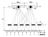
図3は、図2に対する参考例として、従来方式によって、2視点による立体表示を行う場合の原理を示している。基本的には、視点数が2つになっただけであり、図2に示した4視点の場合と表示原理は同じである。表示部6は、複数の画素としてRGBのサブピクセルが交互に配置され、各サブピクセルには第1、第2の番号付けがなされている。第1の視点画像(右眼用画像)と第2の視点画像(左眼用画像)とを、表示部6の画面全体において第1、第2の各サブピクセルに割り当てて表示させる。表示部6の第1、第2の各サブピクセルからの光は、バリア素子7の開口部8によって分離される。第1、第2の各サブピクセルからの光はそれぞれ、第2の距離Z0において、第1、第2の集光領域11,12に分離して到達する。すなわち、画面全体における第1の画素からの光はすべて、バリア素子7の分離機能によって、第2の距離Z0において第1の集光領域11に到達する。同様にして、画面全体における第2の画素からの光はすべて、第2の距離Z0において第2の集光領域12に到達する。第1、第2の集光領域11,12のそれぞれの幅は眼間距離E(一般的には65mm)に等しい。このため、観察者の右眼10Rと左眼10Lとが別々の集光領域に位置し、別々の視点画像を見ることで立体視が行われる。
FIG. 3 shows a principle in the case of performing stereoscopic display from two viewpoints by a conventional method as a reference example for FIG. Basically, the number of viewpoints is only two, and the display principle is the same as in the case of the four viewpoints shown in FIG. In the
[設計上の通常の適視距離(第2の距離Z0)について]
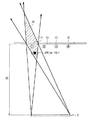
図4を参照して、図2および図3に示したような表示原理による立体表示を行う場合の設計上の適視距離(第2の距離Z0)について説明する。図4に示した例では、表示部6は、例えばバックライト方式の液晶表示パネルとなっており、表示部6の背面側にはバックライト80が配置されている。表示部6は、互いに対向する第1の透明基板61および第2の透明基板62を備え、それらの基板間に画素部63を有している。バリア素子7は、例えば透過型の可変式のパララックスバリア素子であり、互いに対向する第1の透明基板71および第2の透明基板72を備え、それらの基板間に開口部8および遮蔽部9を有している。そのほか、表示部6およびバリア素子7の両面または片面には偏光板や接着層を有している。
[Regarding normal design suitable viewing distance (second distance Z0)]
With reference to FIG. 4, the design suitable viewing distance (second distance Z0) in the case of performing stereoscopic display based on the display principle as shown in FIGS. 2 and 3 will be described. In the example shown in FIG. 4, the
図4において、眼間距離をE、表示部6における画素(またはサブピクセル)間のピッチをPとする。表示部6の画素部63とバリア素子7の開口部8および遮蔽部9とのギャップをGする。また、画素部63と開口部8および遮蔽部9との間に介在する基板等の屈折率をnとする。バリア素子7の表面中心部から、観察者の左眼10Lおよび右眼10Rの中心位置までの距離をAとする。この場合、設計上、以下のような関係式が成り立つ。図2および図3に示したような表示原理での立体表示を行う場合、設計上の通常の適視距離(第2の距離Z0)は、以下の関係式に応じた値となる。
A:E=G/n:P
In FIG. 4, the interocular distance is E, and the pitch between the pixels (or sub-pixels) in the
A: E = G / n: P
[視点位置と観察される画素との関係について]
図5は、図2に示した4視点の立体表示を行う場合において観察者の視点位置が第1の集光領域11にある場合の画素の見え方を示している。また、図6は、観察者の視点位置が第1の集光領域11から所定の距離範囲内にある場合の画素の見え方を示している。なお、図5および図6では、バリア素子7の図示を省略している。後述する図7以降についても同様に、バリア素子7の図示を省略する。
[Relationship between viewpoint position and observed pixels]
FIG. 5 shows how the pixels appear when the viewpoint position of the observer is in the first
図5に示したように、観察者の視点位置が第1の集光領域11にある場合、画面全体における第1の画素からの光はすべて、観察者の右眼10R(または左眼10L)に到達する。また、図6に示したように、視点位置が第1の集光領域11から所定の距離範囲内の所定の領域20にある場合にも、画面全体における第1の画素からの光はすべて、観察者の右眼10R(または左眼10L)に到達する。
As shown in FIG. 5, when the observer's viewpoint position is in the first
図7は、図6の所定の領域20から外れて、観察者の視点位置が第1の集光領域11と第4の集光領域14とから所定の距離範囲内にある場合の画素の見え方を示している。この場合、表示部6の第1の表示領域6Aにおける第1の画素からの光と、第2の表示領域6Bにおける第4の画素からの光とが、観察者の右眼10R(または左眼10L)に到達する。すなわち、この場合、観察者の右眼10R(または左眼10L)は、第1の画素からの光(第1の視点画像)だけでなく、第4の画素からの光(第4の視点画像)も見ることになる。
FIG. 7 shows the appearance of the pixel when the observer's viewpoint position deviates from the
図7に示したように観察者の視点位置が所定の領域20から外れた場合に、どの画素(視点画像)を見ることになるかは、眼に到達した光が、どの集光領域に到達する光であるかを解析すれば良い。
As shown in FIG. 7, when the observer's viewpoint position deviates from the predetermined
図8および図9は、観察者の視点位置が4視点での適視距離(第2の距離Z0)に対して半分の距離(第1の距離Z0/2)にある場合の画素の見え方を示している。第1の距離Z0/2における第1の領域21に右眼10Rが位置し、第1の距離Z0/2における第2の領域22に左眼10Lが位置しているものとする。第1の領域21の幅と第2の領域22の幅はそれぞれ、眼間距離E(一般的には65mm)に等しい。
FIG. 8 and FIG. 9 show how the pixel looks when the observer's viewpoint position is half the distance (first distance Z0 / 2) with respect to the appropriate viewing distance (second distance Z0) at the four viewpoints. Is shown. Assume that the
視点位置が第1の距離Z0/2にある場合、図8に示したように、観察者の右眼10Rと左眼10Lとが見る画素(視点画像)は、設計上の適視距離(第2の距離Z0)に視点位置がある場合に対して互いに2視点分ずれた状態となる。また、図9に示したように、右眼10Rと左眼10Lにはそれぞれ、第1〜第4の画素からの光(第1〜第4の視点画像)が到達する。
When the viewpoint position is at the first distance Z0 / 2, as shown in FIG. 8, the pixel (viewpoint image) viewed by the
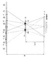
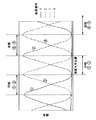
図10(A)は図9に示した観察状態において右眼10Rから見える画素番号と輝度分布を示している。図10(B)は図9に示した観察状態において左眼10Lから見える画素番号と輝度分布を示している。図9に示した観察状態では、右眼10Rと左眼10Lはそれぞれ、表示部6において4つの領域ごとに異なる画素(視点画像)が見える状態となる。4つの領域の幅はそれぞれ、眼間距離E(一般的には65mm)に等しい。具体的には、右眼10Rでは、図10(A)に示したように、表示画面の一方の端部側から順に、第3の画素(第3の視点画像)、第2の画素(第2の視点画像)、第1の画素(第1の視点画像)、第4の画素(第4の視点画像)が見える状態となる。また、左眼10Lでは、図10(B)に示したように、表示画面の一方の端部側から順に、第1の画素(第1の視点画像)、第4の画素(第4の視点画像)、第3の画素(第3の視点画像)、第2の画素(第2の視点画像)が見える状態となる。
FIG. 10A shows the pixel number and luminance distribution that can be seen from the
[視点位置が第1の距離Z0/2にある場合に最適化された立体表示方法]
次に、図11〜図12を参照して、視点位置が第1の距離Z0/2にある場合に最適化された立体表示方法について説明する。上述した図8〜図10の説明から分かるように、視点位置が第1の距離Z0/2にある場合、表示部6に第1〜第4の4つの視点画像を表示したままでは、正常な立体視を行うことができない。そこで、本実施の形態では、視点位置が第1の距離Z0/2にある場合に、表示制御部4が、表示部6に第1〜第4の4つの視点画像に代えて右眼用画像と左眼用画像との2つの視点画像を表示するように制御を行う。
[Stereoscopic display method optimized when the viewpoint position is at the first distance Z0 / 2]
Next, a stereoscopic display method optimized when the viewpoint position is at the first distance Z0 / 2 will be described with reference to FIGS. As can be seen from the description of FIGS. 8 to 10 described above, when the viewpoint position is at the first distance Z0 / 2, it is normal if the first to fourth viewpoint images are displayed on the
図11(A)は、第2の距離Z0において4視点での立体表示が可能な構成である場合(図2参照)に、第1の距離Z0/2において2視点での立体表示が可能となるように設定される複数の分割領域31と各分割領域31に右眼用画像を割り当てる画素番号との対応関係を示してる。図11(B)は図11(A)の場合と同様に設定される複数の分割領域31と各分割領域31に左眼用画像を割り当てる画素番号との対応関係を示している。
FIG. 11A shows a configuration in which stereoscopic display at four viewpoints is possible at the second distance Z0 (see FIG. 2), and stereoscopic display at two viewpoints is possible at the first distance Z0 / 2. The correspondence relationship between the plurality of divided
表示制御部4は、観察者の視点位置が第1の距離Z0/2にある場合に、表示部6の第1から第4の各画素を複数の分割領域31(図11参照)ごとに表示制御し、各分割領域31ごとに第1〜第4の各画素と各視点画像(右眼用画像および左眼用画像)との対応関係を変化させる制御を行う。この場合において、表示制御部4は、右眼用画像と左眼用画像とを各分割領域31ごとに第1〜第4の各画素に割り当て、観察者の視点位置が第1の距離Z0/2にある場合に、右眼10Rの位置から見える第1〜第4の集光領域11〜14に対応する画素には右眼用画像を割り当て、左眼10Lの位置から見える第1〜第4の集光領域11〜14に対応する画素には左眼用画像を割り当てる。表示部6には、各分割領域ごとに第1〜第4の画素が複数存在している。表示制御部4は、各分割領域ごとに第1〜第4の画素のうち連続する2つの画素に右眼用画像を割り当てると共に、第1〜第4の画素のうち連続する他の2つの画素に左眼用画像を割り当てる。また、各分割領域ごとに、右眼用画像を割り当てる2つの画素の組み合わせと、左眼用画像を割り当てる他の2つの画素の組み合わせとを異ならせる。
The
具体的には、表示制御部4は、図11に示したように例えば、第1の分割領域31−1では、第1の画素と第2の画素とに右眼用画像を割り当てると共に、第3の画素と第4の画素とに左眼用画像を割り当てる。また、第1の分割領域31−1に隣接する第2の分割領域31−2では、第2の画素と第3の画素とに右眼用画像を割り当てると共に、第1の画素と第4の画素とに左眼用画像を割り当てる。
Specifically, as illustrated in FIG. 11, for example, in the first divided region 31-1, the
また、表示制御部4は、観察者の視点位置の水平方向の移動に応じて、各分割領域の水平方向の位置(複数の分割領域31の境界線30)を移動させる制御を行う。
In addition, the
図12は、図11(A),(B)に示すような立体表示を行う場合において、隣接する2つの分割領域31−1,31−2間の各画素の輝度分布を模式的に示している。表示制御部4は、観察者の視点位置が第1の距離Z0/2にある場合に、第1の分割領域31−1と第2の分割領域31−2の境界部分を右眼10Rの位置から観察した状態では、第2の画素の輝度に対して第1の画素と第3の画素の輝度が相対的に最も低くなり、左眼10Lの位置から観察した状態では、第4の画素の輝度に対して第1の画素と第3の画素の輝度が相対的に最も低くなるような表示制御を行う。
FIG. 12 schematically shows the luminance distribution of each pixel between two adjacent divided regions 31-1 and 31-2 when performing stereoscopic display as shown in FIGS. Yes. When the observer's viewpoint position is at the first distance Z0 / 2, the
[変形例]
以上の説明では、4視点の場合を例に説明したが、本実施の形態に係る表示装置は、5視点以上の立体表示を行う場合にも適用可能である。図13〜図15には、5視点の立体表示を行う場合の例を示す。この場合、表示部6の複数の画素(またはサブピクセル)には、5つの視点数に応じて第1〜第5の番号付けがなされる。表示制御部4は、観察者の視点位置が5視点での適視距離(第2の距離Z0)にある場合には、複数の視点画像として第1〜第5の視点画像を、表示部6の画面全体において第1〜第5の各画素に割り当てて表示させる。
[Modification]
In the above description, the case of four viewpoints has been described as an example, but the display device according to the present embodiment is also applicable to the case of performing stereoscopic display of five viewpoints or more. FIGS. 13 to 15 show an example in the case of performing stereoscopic display of five viewpoints. In this case, the first to fifth numbers are assigned to the plurality of pixels (or sub-pixels) of the
図13は、観察者の視点位置が5視点での適視距離(第2の距離Z0)に対して半分の距離(第1の距離Z0/2)にある場合の画素の見え方を示している。第1の距離Z0/2における第1の領域21に右眼10Rが位置し、第1の距離Z0/2における第2の領域22に左眼10Lが位置しているものとする。第1の領域21の幅と第2の領域22の幅はそれぞれ、眼間距離E(一般的には65mm)に等しい。
FIG. 13 shows how the pixel looks when the observer's viewpoint position is half the distance (first distance Z0 / 2) with respect to the appropriate viewing distance (second distance Z0) at five viewpoints. Yes. Assume that the
視点位置が第1の距離Z0/2にある場合、図13に示したように、右眼10Rと左眼10Lにはそれぞれ、第1〜第5の画素からの光(第1〜第5の視点画像)が到達する。
When the viewpoint position is at the first distance Z0 / 2, as shown in FIG. 13, each of the
図14(A)は図13に示した観察状態において右眼10Rから見える画素番号と輝度分布を示している。図14(B)は図13に示した観察状態において左眼10Lから見える画素番号と輝度分布を示している。図13に示した観察状態では、右眼10Rと左眼10Lはそれぞれ、表示部6において4つの領域ごとに異なる画素(視点画像)が見える状態となる。4つの領域の幅はそれぞれ、眼間距離E(一般的には65mm)に等しい。具体的には、右眼10Rでは、図14(A)に示したように、表示画面の一方の端部側から順に、第3の画素(第3の視点画像)、第2の画素(第2の視点画像)、第1の画素(第1の視点画像)、第5の画素(第5の視点画像)が見える状態となる。また、左眼10Lでは、図14(B)に示したように、表示画面の一方の端部側から順に、第5の画素(第5の視点画像)、第4の画素(第4の視点画像)、第3の画素(第3の視点画像)、第2の画素(第2の視点画像)が見える状態となる。
FIG. 14A shows the pixel number and luminance distribution that can be seen from the
上述した図13〜図14の説明から分かるように、視点位置が第1の距離Z0/2にある場合、表示部6に第1〜第5の5つの視点画像を表示したままでは、正常な立体視を行うことができない。そこで、視点位置が第1の距離Z0/2にある場合に、表示制御部4が、表示部6に第1〜第5の5つの視点画像に代えて右眼用画像と左眼用画像との2つの視点画像を表示するように制御を行う。
As can be seen from the description of FIGS. 13 to 14 described above, when the viewpoint position is at the first distance Z0 / 2, it is normal if the first to fifth viewpoint images are displayed on the
図15(A)は、第2の距離Z0において5視点での立体表示が可能な構成である場合に、第1の距離Z0/2において2視点での立体表示が可能となるように設定される複数の分割領域31と各分割領域31に右眼用画像を割り当てる画素番号との対応関係を示してる。図15(B)は図15(A)の場合と同様に設定される複数の分割領域31と各分割領域31に左眼用画像を割り当てる画素番号との対応関係を示している。
FIG. 15A is set to enable stereoscopic display at two viewpoints at the first distance Z0 / 2 when the stereoscopic display at five viewpoints is possible at the second distance Z0. The correspondence relationship between the plurality of divided
表示制御部4は、観察者の視点位置が第1の距離Z0/2にある場合に、表示部6の第1から第5の各画素を複数の分割領域31ごとに表示制御し、各分割領域31ごとに第1〜第5の各画素と各視点画像(右眼用画像および左眼用画像)との対応関係を変化させる制御を行う。この場合において、表示制御部4は、右眼用画像と左眼用画像とを各分割領域31ごとに第1〜第5の各画素に割り当て、観察者の視点位置が第1の距離Z0/2にある場合に、右眼10Rの位置から見える第1〜第5の集光領域11〜15に対応する画素には右眼用画像を割り当て、左眼10Lの位置から見える第1〜第5の集光領域11〜15に対応する画素には左眼用画像を割り当てる。表示部6には、各分割領域ごとに第1〜第5の画素が複数存在している。表示制御部4は、各分割領域ごとに第1〜第5の画素のうち連続する2つの画素に右眼用画像を割り当てると共に、第1〜第5の画素のうち連続する他の2つの画素に左眼用画像を割り当てる。また、各分割領域ごとに、右眼用画像を割り当てる2つの画素の組み合わせと、左眼用画像を割り当てる他の2つの画素の組み合わせとを異ならせる。画素の具体的な割り当て手法は、上述した4視点の場合と同様である。
The
[効果]
以上説明したように、本実施の形態に係る表示装置によれば、観察者の視点位置に応じて、第1〜第nの画素に割り当てる複数の視点画像の数および第1〜第nの各画素と各視点画像との対応関係を変化させるようにしたので、視点位置に応じた最適な立体表示を行うことができる。この表示装置によれば、画像処理のみで表示の最適化が可能であり、バリア素子7の移動等を行う必要はなく容易に実施できる。また、観察者の視点位置が第1の距離Z0/2にある場合において、視点位置が水平方向に移動した場合、複数の分割領域31の境界線30を移動させる制御を行うだけで良く、容易に実施できる。また、図12に示したような輝度分布を考慮した最適な表示を行うようにしたので、クロストークの少ない表示を行うことができる。また、複数の分割領域31間での画像の切り換えが判別しにくい状態となるので、観察者に対して自然な見え方となる表示を行うことができる。
[effect]
As described above, according to the display device according to the present embodiment, the number of the plurality of viewpoint images to be assigned to the first to nth pixels and each of the first to nth pixels according to the viewpoint position of the observer. Since the correspondence between the pixel and each viewpoint image is changed, it is possible to perform an optimal stereoscopic display according to the viewpoint position. According to this display device, it is possible to optimize display only by image processing, and it is not necessary to move the
また、従来の技術では、視差分離手段と表示部との間隔が短くなりすぎると、視差分離手段と表示部との間のガラス基板等を薄くするためにガラス研磨等を行う必要が生じ、製造が困難になる。本実施の形態に係る表示装置によれば、設計上の適視距離Z0を遠く設計できるので、ガラス研磨の負荷を軽減することができる。この表示装置において2視点表示を行う場合の視距離は、通常の設計上の適視距離Z0の半分になる。逆に言うと、通常の2視点の立体表示手法(図3)に比べて、設計上の適視距離Z0を2倍、遠く設計することができる。 Further, in the conventional technique, if the distance between the parallax separation means and the display unit becomes too short, it becomes necessary to perform glass polishing or the like in order to make the glass substrate or the like between the parallax separation means and the display unit thin. Becomes difficult. According to the display device according to the present embodiment, the design optimum viewing distance Z0 can be designed to be long, so that the glass polishing load can be reduced. In this display device, the viewing distance when the two-viewpoint display is performed is half of the normal design suitable viewing distance Z0. In other words, the design appropriate viewing distance Z0 can be designed to be twice as long as the normal two-viewpoint stereoscopic display method (FIG. 3).
<その他の実施の形態>
本開示による技術は、上記実施の形態の説明に限定されず種々の変形実施が可能である。
例えば、本技術は以下のような構成を取ることができる。
(1)
第1〜第n(nは4以上の整数)の画素をそれぞれ複数有し、複数の視点画像を前記第1〜第nの各画素に割り当てて表示する表示部と、
観察者の視点位置を検出する検出部と、
前記観察者の視点位置に応じて、前記第1〜第nの画素に割り当てる前記複数の視点画像の数および前記第1〜第nの各画素と前記各視点画像との対応関係を変化させる表示制御部と
表示装置。
(2)
前記表示制御部は、前記観察者の視点位置が前記表示部に対して第1の距離にある場合に、前記表示部の前記各画素を複数の分割領域ごとに表示制御し、前記各分割領域ごとに前記第1〜第nの各画素と前記各視点画像との対応関係を変化させる
上記(1)に記載の表示装置。
(3)
前記表示制御部は、前記観察者の視点位置が前記第1の距離にある場合に、前記複数の視点画像として右眼用画像と左眼用画像とを前記各分割領域ごとに前記第1〜第nの各画素に割り当てる
上記(2)に記載の表示装置。
(4)
前記各分割領域ごとに第1〜第nの画素を複数有し、
前記表示制御部は、前記各分割領域ごとに前記第1〜第nの画素のうち連続する2つの画素に前記右眼用画像を割り当てると共に、前記第1〜第nの画素のうち連続する他の2つの画素に前記左眼用画像を割り当てる
上記(3)に記載の表示装置。
(5)
前記各分割領域ごとに、前記右眼用画像を割り当てる前記2つの画素の組み合わせと、前記左眼用画像を割り当てる前記他の2つの画素の組み合わせとを異ならせる
上記(4)に記載の表示装置。
(6)
前記表示制御部は、前記観察者の視点位置が前記第1の距離にある場合に、
第1の分割領域では、第1の画素と第2の画素とに前記右眼用画像を割り当てると共に、第3の画素と第4の画素とに前記左眼用画像を割り当て、
前記第1の分割領域に隣接する第2の分割領域では、前記第2の画素と前記第3の画素とに前記右眼用画像を割り当てると共に、前記第1の画素と前記第4の画素とに前記左眼用画像を割り当てる
上記(6)に記載の表示装置。
(7)
前記表示制御部は、前記観察者の視点位置が前記第1の距離にある場合に、前記第1の分割領域と前記第2の分割領域の境界部分を右眼位置から観察した状態では、前記第2の画素の輝度に対して前記第1の画素と前記第3の画素の輝度が相対的に低くなり、左眼位置から観察した状態では、前記第4の画素の輝度に対して前記第1の画素と前記第3の画素の輝度が相対的に低くなるような表示制御を行う
上記(6)に記載の表示装置。
(8)
前記表示制御部は、前記観察者の視点位置の水平方向の移動に応じて、前記各分割領域の水平方向の位置を移動させる
上記(2)ないし(7)のいずれか1つに記載の表示装置。
(9)
前記各分割領域の幅は眼間距離に等しい
上記(2)ないし(7)のいずれか1つに記載の表示装置。
(10)
前記第1〜第nの各画素からの光をそれぞれ、第2の距離において第1〜第nの集光領域に分離して到達させる分離部をさらに備え、
前記表示制御部は、前記観察者の視点位置が前記第2の距離にある場合に、前記複数の視点画像として第1〜第nの視点画像を画面全体において前記第1〜第nの各画素に割り当てる
上記(2)ないし(9)のいずれか1つに記載の表示装置。
(11)
前記第1〜第nの集光領域のそれぞれの幅は眼間距離に等しい
上記(10)に記載の表示装置。
(12)
前記第1の距離は、前記第2の距離の半分の距離である
上記(10)または(11)に記載の表示装置。
(13)
前記観察者の視点位置が前記第1の距離にある場合に、右眼位置から見える前記第1〜第nの集光領域に対応する画素には右眼用画像を割り当て、左眼位置から見える前記第1〜第nの集光領域に対応する画素には左眼用画像を割り当てる
上記(10)ないし(12)のいずれか1つに記載の表示装置。
<Other embodiments>
The technology according to the present disclosure is not limited to the description of the above embodiment, and various modifications can be made.
For example, the present technology can take the following configurations.
(1)
A display unit that includes a plurality of first to nth (n is an integer of 4 or more) pixels, and displays a plurality of viewpoint images assigned to the first to nth pixels;
A detection unit for detecting the observer's viewpoint position;
Display that changes the number of the plurality of viewpoint images assigned to the first to n-th pixels and the correspondence between the first to n-th pixels and the viewpoint images according to the viewpoint position of the observer Control unit and display device.
(2)
The display control unit controls display of each pixel of the display unit for each of a plurality of divided regions when the observer's viewpoint position is at a first distance from the display unit, The display device according to (1), wherein the correspondence relationship between each of the first to nth pixels and each viewpoint image is changed every time.
(3)
When the observer's viewpoint position is at the first distance, the display control unit converts the first eye image and the left eye image as the plurality of viewpoint images for each of the divided regions. The display device according to (2), wherein the display device is assigned to each nth pixel.
(4)
A plurality of first to nth pixels for each of the divided regions;
The display control unit assigns the right-eye image to two consecutive pixels among the first to n-th pixels for each of the divided regions, and other continuous ones among the first to n-th pixels. The display device according to (3), wherein the left-eye image is assigned to the two pixels.
(5)
The display device according to (4), wherein the combination of the two pixels to which the right-eye image is assigned differs from the combination of the other two pixels to which the left-eye image is assigned for each divided region. .
(6)
The display control unit, when the viewpoint position of the observer is at the first distance,
In the first divided region, the image for the right eye is allocated to the first pixel and the second pixel, and the image for the left eye is allocated to the third pixel and the fourth pixel.
In the second divided region adjacent to the first divided region, the right eye image is allocated to the second pixel and the third pixel, and the first pixel and the fourth pixel are assigned to the second pixel and the third pixel. The display device according to (6), wherein the left-eye image is assigned to the display device.
(7)
In the state where the boundary portion between the first divided region and the second divided region is observed from the right eye position when the observer's viewpoint position is at the first distance, The luminance of the first pixel and the third pixel is relatively lower than the luminance of the second pixel, and when viewed from the left eye position, the luminance of the fourth pixel is higher than that of the fourth pixel. The display device according to (6), wherein display control is performed such that the luminance of one pixel and the third pixel is relatively low.
(8)
The display according to any one of (2) to (7), wherein the display control unit moves a horizontal position of each of the divided regions in accordance with a horizontal movement of the viewpoint position of the observer. apparatus.
(9)
The display device according to any one of (2) to (7), wherein a width of each divided region is equal to an interocular distance.
(10)
A separation unit for separating and reaching the light from each of the first to n-th pixels at the second distance to the first to n-th light collecting regions, respectively;
The display control unit displays the first to nth viewpoint images as the plurality of viewpoint images on the entire screen when the observer's viewpoint position is at the second distance. The display device according to any one of (2) to (9).
(11)
The display device according to (10), wherein each width of the first to nth light condensing regions is equal to an interocular distance.
(12)
The display device according to (10) or (11), wherein the first distance is a half of the second distance.
(13)
When the observer's viewpoint position is at the first distance, a right-eye image is assigned to the pixels corresponding to the first to nth condensing regions that are visible from the right eye position, and the image is viewed from the left eye position. The display device according to any one of (10) to (12), wherein a left-eye image is assigned to pixels corresponding to the first to nth light condensing regions.
1…検出部、2…撮像部、3…視点位置判定部、4…表示制御部、5…画像生成部、6…表示部、6A…第1の表示領域、6B…第2の表示領域、7…バリア素子、8…開口部、9…遮蔽部、10L…左眼、10R…右眼、11,21…第1の集光領域、12,22…第2の集光領域、13…第3の集光領域、14…第4の集光領域、15…第5の集光領域、20…領域、31…分割領域、31−1…第1の分割領域、31−2…第2の分割領域、61,71…第1の透明基板、62,72…第2の透明基板、63…画素部、80…バックライト、E…眼間距離、G…ギャップ、P…画素ピッチ(サブピクセルピッチ)、Z0…適視距離(第2の距離)、Z0/2…第1の距離。
DESCRIPTION OF
Claims (13)
観察者の視点位置を検出する検出部と、
前記観察者の視点位置に応じて、前記第1〜第nの画素に割り当てる前記複数の視点画像の数および前記第1〜第nの各画素と前記各視点画像との対応関係を変化させる表示制御部と
を備えた表示装置。 A display unit that includes a plurality of first to nth (n is an integer of 4 or more) pixels, and displays a plurality of viewpoint images assigned to the first to nth pixels;
A detection unit for detecting the observer's viewpoint position;
Display that changes the number of the plurality of viewpoint images assigned to the first to n-th pixels and the correspondence between the first to n-th pixels and the viewpoint images according to the viewpoint position of the observer A display device comprising a control unit.
請求項1に記載の表示装置。 The display control unit controls display of each pixel of the display unit for each of a plurality of divided regions when the observer's viewpoint position is at a first distance from the display unit, The display device according to claim 1, wherein the correspondence relationship between each of the first to nth pixels and each viewpoint image is changed every time.
請求項2に記載の表示装置。 When the observer's viewpoint position is at the first distance, the display control unit converts the first eye image and the left eye image as the plurality of viewpoint images for each of the divided regions. The display device according to claim 2, wherein the display device is assigned to each nth pixel.
前記表示制御部は、前記各分割領域ごとに前記第1〜第nの画素のうち連続する2つの画素に前記右眼用画像を割り当てると共に、前記第1〜第nの画素のうち連続する他の2つの画素に前記左眼用画像を割り当てる
請求項3に記載の表示装置。 A plurality of first to nth pixels for each of the divided regions;
The display control unit assigns the right-eye image to two consecutive pixels among the first to n-th pixels for each of the divided regions, and other continuous ones among the first to n-th pixels. The display device according to claim 3, wherein the left-eye image is assigned to the two pixels.
請求項4に記載の表示装置。 The display device according to claim 4, wherein the combination of the two pixels to which the right-eye image is assigned differs from the combination of the other two pixels to which the left-eye image is assigned for each divided region.
第1の分割領域では、第1の画素と第2の画素とに前記右眼用画像を割り当てると共に、第3の画素と第4の画素とに前記左眼用画像を割り当て、
前記第1の分割領域に隣接する第2の分割領域では、前記第2の画素と前記第3の画素とに前記右眼用画像を割り当てると共に、前記第1の画素と前記第4の画素とに前記左眼用画像を割り当てる
請求項5に記載の表示装置。 The display control unit, when the viewpoint position of the observer is at the first distance,
In the first divided region, the image for the right eye is allocated to the first pixel and the second pixel, and the image for the left eye is allocated to the third pixel and the fourth pixel.
In the second divided region adjacent to the first divided region, the right eye image is allocated to the second pixel and the third pixel, and the first pixel and the fourth pixel are assigned to the second pixel and the third pixel. The display device according to claim 5, wherein the left-eye image is assigned to the display device.
請求項6に記載の表示装置。 In the state where the boundary portion between the first divided region and the second divided region is observed from the right eye position when the observer's viewpoint position is at the first distance, The luminance of the first pixel and the third pixel is relatively lower than the luminance of the second pixel, and when viewed from the left eye position, the luminance of the fourth pixel is higher than that of the fourth pixel. The display device according to claim 6, wherein display control is performed such that the luminance of one pixel and the third pixel is relatively low.
請求項2に記載の表示装置。 The display device according to claim 2, wherein the display control unit moves a horizontal position of each of the divided regions in accordance with a horizontal movement of the viewpoint position of the observer.
請求項2に記載の表示装置。 The display device according to claim 2, wherein a width of each divided region is equal to an interocular distance.
前記表示制御部は、前記観察者の視点位置が前記第2の距離にある場合に、前記複数の視点画像として第1〜第nの視点画像を画面全体において前記第1〜第nの各画素に割り当てる
請求項2に記載の表示装置。 A separation unit for separating and reaching the light from each of the first to n-th pixels at the second distance to the first to n-th light collecting regions, respectively;
The display control unit displays the first to nth viewpoint images as the plurality of viewpoint images on the entire screen when the observer's viewpoint position is at the second distance. The display device according to claim 2.
請求項10に記載の表示装置。 The display device according to claim 10, wherein a width of each of the first to nth light collection regions is equal to an interocular distance.
請求項10に記載の表示装置。 The display device according to claim 10, wherein the first distance is a half of the second distance.
請求項10に記載の表示装置。 When the observer's viewpoint position is at the first distance, a right-eye image is assigned to the pixels corresponding to the first to nth condensing regions that are visible from the right eye position, and the image is viewed from the left eye position. The display device according to claim 10, wherein a left-eye image is assigned to pixels corresponding to the first to nth light condensing regions.
Priority Applications (9)
| Application Number | Priority Date | Filing Date | Title |
|---|---|---|---|
| JP2011068153A JP5710330B2 (en) | 2011-03-25 | 2011-03-25 | Display device |
| KR1020120023231A KR101933219B1 (en) | 2011-03-25 | 2012-03-07 | Display |
| US13/416,425 US8994759B2 (en) | 2011-03-25 | 2012-03-09 | Display |
| TW101108859A TWI497977B (en) | 2011-03-25 | 2012-03-15 | Display |
| RU2012110166/28A RU2012110166A (en) | 2011-03-25 | 2012-03-16 | DISPLAY DEVICE |
| BRBR102012005940-1A BR102012005940A2 (en) | 2011-03-25 | 2012-03-16 | Exhibitor |
| EP12159859.3A EP2521368A3 (en) | 2011-03-25 | 2012-03-16 | stereoscopic display device with viewer tracking |
| IN764DE2012 IN2012DE00764A (en) | 2011-03-25 | 2012-03-16 | |
| CN201210081998.3A CN102695073B (en) | 2011-03-25 | 2012-03-26 | Display |
Applications Claiming Priority (1)
| Application Number | Priority Date | Filing Date | Title |
|---|---|---|---|
| JP2011068153A JP5710330B2 (en) | 2011-03-25 | 2011-03-25 | Display device |
Publications (2)
| Publication Number | Publication Date |
|---|---|
| JP2012203230A true JP2012203230A (en) | 2012-10-22 |
| JP5710330B2 JP5710330B2 (en) | 2015-04-30 |
Family
ID=45936788
Family Applications (1)
| Application Number | Title | Priority Date | Filing Date |
|---|---|---|---|
| JP2011068153A Active JP5710330B2 (en) | 2011-03-25 | 2011-03-25 | Display device |
Country Status (9)
| Country | Link |
|---|---|
| US (1) | US8994759B2 (en) |
| EP (1) | EP2521368A3 (en) |
| JP (1) | JP5710330B2 (en) |
| KR (1) | KR101933219B1 (en) |
| CN (1) | CN102695073B (en) |
| BR (1) | BR102012005940A2 (en) |
| IN (1) | IN2012DE00764A (en) |
| RU (1) | RU2012110166A (en) |
| TW (1) | TWI497977B (en) |
Cited By (1)
| Publication number | Priority date | Publication date | Assignee | Title |
|---|---|---|---|---|
| JP2016071008A (en) * | 2014-09-29 | 2016-05-09 | 株式会社ジャパンディスプレイ | Display device |
Families Citing this family (23)
| Publication number | Priority date | Publication date | Assignee | Title |
|---|---|---|---|---|
| US11275242B1 (en) | 2006-12-28 | 2022-03-15 | Tipping Point Medical Images, Llc | Method and apparatus for performing stereoscopic rotation of a volume on a head display unit |
| US11315307B1 (en) | 2006-12-28 | 2022-04-26 | Tipping Point Medical Images, Llc | Method and apparatus for performing rotating viewpoints using a head display unit |
| US9349183B1 (en) * | 2006-12-28 | 2016-05-24 | David Byron Douglas | Method and apparatus for three dimensional viewing of images |
| US10795457B2 (en) | 2006-12-28 | 2020-10-06 | D3D Technologies, Inc. | Interactive 3D cursor |
| US11228753B1 (en) | 2006-12-28 | 2022-01-18 | Robert Edwin Douglas | Method and apparatus for performing stereoscopic zooming on a head display unit |
| JP5167439B1 (en) * | 2012-02-15 | 2013-03-21 | パナソニック株式会社 | Stereoscopic image display apparatus and stereoscopic image display method |
| CN102681185B (en) * | 2012-05-30 | 2014-07-30 | 深圳超多维光电子有限公司 | Three-dimensional display device and adjusting method thereof |
| CN103096109B (en) * | 2013-01-18 | 2015-05-06 | 昆山龙腾光电有限公司 | Multiple view automatic stereoscopic displayer and display method |
| TWI515457B (en) * | 2013-01-23 | 2016-01-01 | 友達光電股份有限公司 | Multi-view three dimensional display system and control method thereof |
| TWI495327B (en) * | 2013-02-07 | 2015-08-01 | Au Optronics Corp | Displaying apparatus and operating method thereof |
| CN103197474A (en) * | 2013-03-29 | 2013-07-10 | 信利半导体有限公司 | Three-dimensional display device and liquid crystal grating and control method thereof |
| JP2014206638A (en) * | 2013-04-12 | 2014-10-30 | 株式会社ジャパンディスプレイ | Stereoscopic display device |
| KR20160025522A (en) * | 2013-06-28 | 2016-03-08 | 톰슨 라이센싱 | Multi-view three-dimensional display system and method with position sensing and adaptive number of views |
| EP2854403A1 (en) | 2013-09-30 | 2015-04-01 | Samsung Electronics Co., Ltd | Image generating apparatus and display device for layered display scheme based on location of eye of user |
| CN104010179B (en) * | 2014-06-12 | 2015-03-04 | 山东大学 | Multi-user clustering and viewpoint calculating system and method based on multiple three-dimensional pictures |
| CN105911712B (en) * | 2016-06-30 | 2018-12-04 | 北京邮电大学 | A kind of multiple views liquid crystal display LCD naked eye 3D display method and device |
| KR101825063B1 (en) * | 2017-10-30 | 2018-02-02 | 주식회사 셀빅 | The hardware system for inputting 3D image in a flat panel |
| CN112015264B (en) * | 2019-05-30 | 2023-10-20 | 深圳市冠旭电子股份有限公司 | Virtual reality display method, virtual reality display device and virtual reality equipment |
| US20220199046A1 (en) * | 2019-09-06 | 2022-06-23 | Hewlett-Packard Development Company, L.P. | Display backlight adjustment based on viewer position |
| WO2021133738A1 (en) * | 2019-12-24 | 2021-07-01 | Lumileds Llc | Multiview display using microled technology |
| JP2021141424A (en) * | 2020-03-04 | 2021-09-16 | 富士フイルムビジネスイノベーション株式会社 | Display system, display control device, and program |
| JP2021141423A (en) * | 2020-03-04 | 2021-09-16 | 富士フイルムビジネスイノベーション株式会社 | Display system, display control device, and program |
| EP4124033A1 (en) | 2021-07-23 | 2023-01-25 | VitreaLab GmbH | Stereoscopic display device |
Citations (4)
| Publication number | Priority date | Publication date | Assignee | Title |
|---|---|---|---|---|
| JPH09160144A (en) * | 1995-12-12 | 1997-06-20 | Sharp Corp | Three-dimensional display device |
| JP2002519897A (en) * | 1998-06-20 | 2002-07-02 | クリストフ グロスマン, | Method and apparatus for autostereoscopic images |
| JP2008185629A (en) * | 2007-01-26 | 2008-08-14 | Seiko Epson Corp | Image display device |
| JP2010008719A (en) * | 2008-06-27 | 2010-01-14 | Seiko Epson Corp | Three-dimensional display |
Family Cites Families (9)
| Publication number | Priority date | Publication date | Assignee | Title |
|---|---|---|---|---|
| JP2983891B2 (en) | 1995-05-30 | 1999-11-29 | 三洋電機株式会社 | 3D display device |
| DE59708088D1 (en) | 1996-12-18 | 2002-10-02 | Dresden 3D Gmbh | METHOD AND ARRANGEMENT FOR THE THREE-DIMENSIONAL PRESENTATION OF INFORMATION |
| EP1087627A3 (en) * | 1999-09-24 | 2004-02-18 | SANYO ELECTRIC Co., Ltd. | Autostereoscopic image display device |
| US7277121B2 (en) | 2001-08-29 | 2007-10-02 | Sanyo Electric Co., Ltd. | Stereoscopic image processing and display system |
| US7425951B2 (en) | 2002-12-27 | 2008-09-16 | Kabushiki Kaisha Toshiba | Three-dimensional image display apparatus, method of distributing elemental images to the display apparatus, and method of displaying three-dimensional image on the display apparatus |
| DE102006031799B3 (en) * | 2006-07-06 | 2008-01-31 | Fraunhofer-Gesellschaft zur Förderung der angewandten Forschung e.V. | Method for autostereoscopic display of image information with adaptation to changes in the head position of the viewer |
| DE102009009443B3 (en) | 2009-02-14 | 2010-09-23 | Fraunhofer-Gesellschaft zur Förderung der angewandten Forschung e.V. | Monitor and method for displaying autostereoscopic images |
| JP2011068153A (en) | 2009-09-22 | 2011-04-07 | Denso Corp | Air conditioner for vehicle |
| KR101783663B1 (en) * | 2010-11-05 | 2017-10-11 | 엘지디스플레이 주식회사 | Image display device and driving method for thereof |
-
2011
- 2011-03-25 JP JP2011068153A patent/JP5710330B2/en active Active
-
2012
- 2012-03-07 KR KR1020120023231A patent/KR101933219B1/en active IP Right Grant
- 2012-03-09 US US13/416,425 patent/US8994759B2/en active Active
- 2012-03-15 TW TW101108859A patent/TWI497977B/en active
- 2012-03-16 EP EP12159859.3A patent/EP2521368A3/en not_active Withdrawn
- 2012-03-16 BR BRBR102012005940-1A patent/BR102012005940A2/en not_active Application Discontinuation
- 2012-03-16 RU RU2012110166/28A patent/RU2012110166A/en not_active Application Discontinuation
- 2012-03-16 IN IN764DE2012 patent/IN2012DE00764A/en unknown
- 2012-03-26 CN CN201210081998.3A patent/CN102695073B/en active Active
Patent Citations (4)
| Publication number | Priority date | Publication date | Assignee | Title |
|---|---|---|---|---|
| JPH09160144A (en) * | 1995-12-12 | 1997-06-20 | Sharp Corp | Three-dimensional display device |
| JP2002519897A (en) * | 1998-06-20 | 2002-07-02 | クリストフ グロスマン, | Method and apparatus for autostereoscopic images |
| JP2008185629A (en) * | 2007-01-26 | 2008-08-14 | Seiko Epson Corp | Image display device |
| JP2010008719A (en) * | 2008-06-27 | 2010-01-14 | Seiko Epson Corp | Three-dimensional display |
Cited By (1)
| Publication number | Priority date | Publication date | Assignee | Title |
|---|---|---|---|---|
| JP2016071008A (en) * | 2014-09-29 | 2016-05-09 | 株式会社ジャパンディスプレイ | Display device |
Also Published As
| Publication number | Publication date |
|---|---|
| RU2012110166A (en) | 2013-09-27 |
| EP2521368A3 (en) | 2013-11-06 |
| KR20120109303A (en) | 2012-10-08 |
| KR101933219B1 (en) | 2019-03-15 |
| IN2012DE00764A (en) | 2015-08-21 |
| CN102695073B (en) | 2016-08-17 |
| EP2521368A2 (en) | 2012-11-07 |
| CN102695073A (en) | 2012-09-26 |
| BR102012005940A2 (en) | 2015-08-18 |
| JP5710330B2 (en) | 2015-04-30 |
| TWI497977B (en) | 2015-08-21 |
| US8994759B2 (en) | 2015-03-31 |
| TW201301862A (en) | 2013-01-01 |
| US20120242569A1 (en) | 2012-09-27 |
Similar Documents
| Publication | Publication Date | Title |
|---|---|---|
| JP5710330B2 (en) | Display device | |
| JP5643160B2 (en) | Display device | |
| US9479767B2 (en) | Autostereoscopic display device and drive method | |
| JP5762998B2 (en) | Display device and electronic device | |
| JP6154323B2 (en) | Video display device | |
| JP5321575B2 (en) | Autostereoscopic display device | |
| KR20110087189A (en) | Three-dimensional video imaging device | |
| US9420268B2 (en) | Apparatus and method for displaying 3-dimensional image | |
| TW201226983A (en) | Stereoscopic display device | |
| JP2010524309A (en) | Method and configuration for three-dimensional display | |
| JP2010282090A (en) | Stereoscopic image display device | |
| KR20130141867A (en) | 3 dimensional image display device and driving method thereof | |
| KR100828696B1 (en) | Variable parallax barrier and stereoscopic parallax barrier lcd | |
| JP2014510935A (en) | Parallax barrier and stereoscopic display device including the parallax barrier | |
| JP2014032366A (en) | Display device and electronic equipment | |
| KR20130015936A (en) | An apparatus and a method for displaying a 3-dimensional image | |
| JP2014510936A (en) | 3D display device | |
| JP2013187655A (en) | Display device and electronic apparatus | |
| JP2013015711A (en) | Display device | |
| KR101360780B1 (en) | Glassesless 3 dimensional display apparatus | |
| KR20140104255A (en) | Apparatus and method for displaying 3-dimension image |
Legal Events
| Date | Code | Title | Description |
|---|---|---|---|
| RD03 | Notification of appointment of power of attorney |
Free format text: JAPANESE INTERMEDIATE CODE: A7423 Effective date: 20130328 |
|
| A621 | Written request for application examination |
Free format text: JAPANESE INTERMEDIATE CODE: A621 Effective date: 20140110 |
|
| A711 | Notification of change in applicant |
Free format text: JAPANESE INTERMEDIATE CODE: A712 Effective date: 20140110 |
|
| A977 | Report on retrieval |
Free format text: JAPANESE INTERMEDIATE CODE: A971007 Effective date: 20141006 |
|
| A131 | Notification of reasons for refusal |
Free format text: JAPANESE INTERMEDIATE CODE: A131 Effective date: 20141021 |
|
| A521 | Request for written amendment filed |
Free format text: JAPANESE INTERMEDIATE CODE: A523 Effective date: 20141219 |
|
| TRDD | Decision of grant or rejection written | ||
| A01 | Written decision to grant a patent or to grant a registration (utility model) |
Free format text: JAPANESE INTERMEDIATE CODE: A01 Effective date: 20150217 |
|
| A61 | First payment of annual fees (during grant procedure) |
Free format text: JAPANESE INTERMEDIATE CODE: A61 Effective date: 20150304 |
|
| R150 | Certificate of patent or registration of utility model |
Ref document number: 5710330 Country of ref document: JP Free format text: JAPANESE INTERMEDIATE CODE: R150 |
|
| R250 | Receipt of annual fees |
Free format text: JAPANESE INTERMEDIATE CODE: R250 |
|
| R250 | Receipt of annual fees |
Free format text: JAPANESE INTERMEDIATE CODE: R250 |
|
| R250 | Receipt of annual fees |
Free format text: JAPANESE INTERMEDIATE CODE: R250 |
|
| R250 | Receipt of annual fees |
Free format text: JAPANESE INTERMEDIATE CODE: R250 |
|
| R250 | Receipt of annual fees |
Free format text: JAPANESE INTERMEDIATE CODE: R250 |
|
| R250 | Receipt of annual fees |
Free format text: JAPANESE INTERMEDIATE CODE: R250 |
|
| R250 | Receipt of annual fees |
Free format text: JAPANESE INTERMEDIATE CODE: R250 |