JP2012202957A - Defect position information generation device, defect confirmation system, and defect position information generation method - Google Patents
Defect position information generation device, defect confirmation system, and defect position information generation method Download PDFInfo
- Publication number
- JP2012202957A JP2012202957A JP2011070671A JP2011070671A JP2012202957A JP 2012202957 A JP2012202957 A JP 2012202957A JP 2011070671 A JP2011070671 A JP 2011070671A JP 2011070671 A JP2011070671 A JP 2011070671A JP 2012202957 A JP2012202957 A JP 2012202957A
- Authority
- JP
- Japan
- Prior art keywords
- defect
- position information
- origin
- sheet material
- captured image
- Prior art date
- Legal status (The legal status is an assumption and is not a legal conclusion. Google has not performed a legal analysis and makes no representation as to the accuracy of the status listed.)
- Withdrawn
Links
Images


Abstract
Description
本発明は、長尺シート材における欠陥の位置を示す欠陥位置情報を生成する欠陥位置情報生成装置等の技術分野に関する。 The present invention relates to a technical field such as a defect position information generation device that generates defect position information indicating a position of a defect in a long sheet material.
従来、ポリエチレンフィルム等の長尺シート材における欠陥(穴、傷、凹み、汚れ、異物の付着など)を検査する場合、第1段階で、欠陥特定装置により欠陥箇所を特定し、第2段階で、当該特定された欠陥箇所を検査官が実際に確認(レビュー)している。 Conventionally, when inspecting defects (holes, scratches, dents, dirt, adhesion of foreign matter, etc.) in a long sheet material such as polyethylene film, the defect location is identified by the defect identification device in the first stage, and in the second stage. The inspector actually confirms (reviews) the identified defective part.
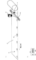
図1に示すように、第1段階では、長尺のシート材Sを図示しない搬送ローラで搬送しつつ、背面から蛍光灯Fにより照らされたシート材Sの表面をラインセンサカメラCにより撮影し、撮影画像を図示しない欠陥特定装置に送信する。欠陥特定装置は、受信した撮影画像からシート材Sに欠陥Dがあるか否かを公知の欠陥判定方法により判定し、欠陥Dがあると判定した場合には当該欠陥Dの位置を示す欠陥座標を出力する。このとき、欠陥座標は、検査基準位置Oを原点とする座標となる。すなわち、欠陥座標(Xn,Yn)におけるXnは検査基準位置Oを基準とする幅方向距離Lxから特定され、Ynは検査基準位置Oを基準とする搬送方向距離Lyから特定される。欠陥特定装置により出力された欠陥座標は検査官に報告され、第2段階で利用されるようになっている。 As shown in FIG. 1, in the first stage, the surface of the sheet material S illuminated by the fluorescent lamp F from the back is photographed by the line sensor camera C while the long sheet material S is conveyed by a conveyance roller (not shown). The captured image is transmitted to a defect identification device (not shown). The defect identification device determines whether or not the sheet material S has a defect D from the received photographed image by a known defect determination method, and when it is determined that there is the defect D, the defect coordinates indicating the position of the defect D Is output. At this time, the defect coordinates are coordinates having the inspection reference position O as the origin. That is, X n in the defect coordinates (X n, Y n) is determined from the width direction distance Lx relative to the inspection standard position O, Y n are identified from the feeding direction distance Ly relative to the inspection standard position O . The defect coordinates output by the defect identification device are reported to the inspector and used in the second stage.
第2段階では、検査官は巻き直されたシート材Sが搬送される際、欠陥特定装置により出力された欠陥座標に基づいて欠陥箇所を探し出し、実際に欠陥とするか否かを判断する。ところが、検査官が欠陥座標に基づいて欠陥箇所を探す際、欠陥座標の示す位置に欠陥であるか否かを判断すべき対象がない場合がある。これは、ロータリーエンコーダ(搬送ローラの回転量等を計測する機器)の第1段階と第2段階とにおける誤差(第1段階で搬送した距離と、第2段階で搬送した距離の誤差)、シート材Sの伸縮、ロールのすべり等の原因によるものであり、特に欠陥座標のYnの値が大きい場合(すなわち、検査基準位置から欠陥位置が離れている場合)に起こりやすい。 In the second stage, when the re-rolled sheet material S is conveyed, the inspector searches for a defective portion based on the defect coordinates output by the defect identification device, and determines whether or not the defect is actually set as a defect. However, when the inspector searches for a defect location based on the defect coordinates, there is a case where there is no target to determine whether or not there is a defect at the position indicated by the defect coordinates. This is because of errors in the first stage and the second stage of the rotary encoder (device for measuring the rotation amount of the transport roller) (the error in the distance transported in the first stage and the distance transported in the second stage), the sheet This is due to causes such as expansion and contraction of the material S, slipping of the roll, and the like, and is likely to occur particularly when the value of Y n of the defect coordinates is large (that is, when the defect position is away from the inspection reference position).
そこで、第1段階において欠陥位置に直接マーキングする技術が開示されている(例えば、特許文献1、2)。当該技術によれば、欠陥箇所に直接マーキングがなされるため、検査官が欠陥を確認する際、欠陥箇所を一目で見つけられるという利点がある。
Therefore, techniques for directly marking defect positions in the first stage are disclosed (for example,
しかしながら、欠陥箇所に直接マーキングする場合、欠陥箇所を上流の検査位置から下流のマーキング位置に搬送されるまでの間に特定し、的確にマーキングするという高度な技術が求められる。そのため、装置が高額になりやすいという問題がある。また、欠陥判定に誤りがあった場合には、欠陥でない位置にマーキングがなされ、その部分が欠陥となってしまうという問題がある。 However, when marking a defective part directly, an advanced technique is required for identifying and accurately marking the defective part before it is conveyed from the upstream inspection position to the downstream marking position. Therefore, there is a problem that the device tends to be expensive. In addition, when there is an error in the defect determination, there is a problem that marking is made at a position that is not a defect, and that portion becomes a defect.
本発明は、このような問題等に鑑みて為されたもので、欠陥箇所に直接マーキングすることなく、検査官が長尺シート材における欠陥箇所をすみやかに特定することのできる欠陥位置情報生成装置等を提供することを課題とする。 The present invention has been made in view of such problems and the like, and a defect position information generation device that allows an inspector to quickly identify a defect portion in a long sheet material without directly marking the defect portion. Etc. to be provided.
上記課題を解決するために、請求項1に記載の発明は、長手方向に搬送される長尺シート材における欠陥の位置を示す欠陥位置情報を生成する欠陥位置情報生成装置であって、原点と当該原点を識別するための記号との組合せが前記長手方向に複数印字された前記長尺シート材の撮影画像を取得する撮影画像取得手段と、前記取得された撮影画像において、前記原点及び前記欠陥の位置を特定する特定手段と、前記特定された原点のうち前記特定された欠陥の位置に1番目又は2番目に近い原点を基準として、当該特定された欠陥の位置を示す欠陥座標を算出する欠陥座標算出手段と、前記基準となった原点と前記組合せをなす前記記号を示す記号情報と、前記算出された欠陥座標を示す欠陥座標情報とを含む前記欠陥位置情報を生成する欠陥位置情報生成手段と、を備えることを特徴とする。
In order to solve the above-mentioned problem, the invention described in
請求項2に記載の発明は、請求項1に記載の欠陥位置情報生成装置であって、前記記号は数字であり、前記長尺シート材の長手方向に連番となるように印字されていることを特徴とする。
The invention according to
請求項3に記載の発明は、請求項1又は2に記載の欠陥位置情報生成装置であって、前記原点及び前記記号は、前記長尺シート材の幅方向における所定範囲内に複数印字され、前記特定手段は、前記取得された撮影画像における欠陥候補を特定し、前記特定した欠陥候補の位置が、前記取得された撮影画像において前記所定範囲を示す情報により示される当該所定範囲内に含まれないと判定した場合に、当該特定した欠陥候補を前記欠陥として特定することを特徴とする。
The invention according to
請求項4に記載の発明は、請求項1乃至3の何れか一項に記載の欠陥位置情報生成装置であって、各前記原点は、前記長尺シート材の幅方向における所定範囲内において、前記長尺シート材の長手方向に所定間隔毎に印字され、前記特定手段は、前記取得された撮影画像における欠陥候補を特定し、前記特定した欠陥候補の位置が、前記取得された撮影画像において前記所定範囲を示す情報により示される当該所定範囲内に含まれると判定し、且つ、前記特定した欠陥候補の位置が、前記取得された撮影画像において直前に特定した原点から、前記所定間隔を示す情報により示される当該所定距離とほぼ同じ距離にあると判定した場合に、当該欠陥候補を前記原点として特定することを特徴とする。
Invention of Claim 4 is the defect position information generation apparatus as described in any one of
請求項5に記載の発明は、請求項1乃至4の何れか一項に記載の欠陥位置情報生成装置であって、前記原点と前記記号との組合せが複数印字された前記長尺シート材を撮影する撮影手段を、更に備えることを特徴とする。
The invention according to claim 5 is the defect position information generation device according to any one of
請求項6に記載の発明は、請求項1乃至5の何れか一項に記載の欠陥位置情報生成装置と、欠陥確認装置と、を有する欠陥確認システムであって、前記欠陥確認装置は、前記欠陥位置情報生成装置により生成された前記欠陥位置情報を取得する欠陥位置情報取得手段と、前記欠陥位置情報生成装置により前記欠陥位置情報が生成された前記長尺シート材を長手方向に搬送する搬送手段と、前記搬送される長尺シート材における前記記号が印字された部分を撮影する印字部撮影手段と、前記取得された欠陥位置情報における記号情報の示す記号と同じ記号が、前記印字部撮影手段により撮影された場合に、前記搬送手段による搬送を停止させる搬送制御手段と、を備えることを特徴とする。
Invention of Claim 6 is a defect confirmation system which has the defect position information generation apparatus as described in any one of
請求項7に記載の発明は、長手方向に搬送される長尺シート材における欠陥の位置を示す欠陥位置情報を生成する欠陥位置情報生成装置による欠陥位置情報生成方法であって、原点と当該原点を識別するための記号との組合せが前記長手方向に複数印字された前記長尺シート材の撮影画像を取得する撮影画像取得工程と、前記取得された撮影画像において、前記原点及び前記欠陥の位置を特定する特定工程と、前記特定された原点のうち前記特定された欠陥の位置に1番目又は2番目に近い原点を基準として、当該特定された欠陥の位置を示す欠陥座標を算出する欠陥座標算出工程と、前記基準となった原点と前記組合せをなす前記記号を示す記号情報と、前記算出された欠陥座標を示す欠陥座標情報とを含む前記欠陥位置情報を生成する欠陥位置情報生成工程と、を含むことを特徴とする。 The invention according to claim 7 is a defect position information generation method by a defect position information generation device that generates defect position information indicating a position of a defect in a long sheet material conveyed in the longitudinal direction, the origin and the origin A captured image acquisition step of acquiring a captured image of the long sheet material in which a plurality of combinations with symbols for identifying the longitudinal direction are printed, and the origin and the position of the defect in the acquired captured image And a defect coordinate for calculating a defect coordinate indicating the position of the specified defect with reference to the first or second closest origin to the position of the specified defect among the specified origins The defect position information including the calculation step, the symbol information indicating the symbol that forms the combination with the reference origin, and the defect coordinate information indicating the calculated defect coordinate is generated. A position information generation step, characterized in that it comprises a.
本発明によれば、長尺シート材に印字された原点のうち、欠陥に1番目又は2番目に近い原点を基準とする欠陥座標を示す欠陥座標情報と、当該基準となった原点と組合せをなす記号を示す記号情報とを含む欠陥位置情報が生成される。したがって、欠陥箇所に直接マーキングされることはなく、検査官は、記号情報の示す記号と組合せをなす原点を基準として、欠陥座標情報の示す位置を探すことにより欠陥箇所を特定することができる。すなわち、検査官は、欠陥に近い原点を基準に欠陥箇所を探すこととなるので、図1に示すように検査基準位置Oを基準に欠陥箇所を探す場合と比較して、すみやかに欠陥位置を特定することができる。 According to the present invention, out of the origins printed on the long sheet material, the defect coordinate information indicating the defect coordinates based on the origin that is the first or second closest to the defect, and the combination of the origin that is the reference Defect position information including symbol information indicating a formed symbol is generated. Therefore, the defect portion is not directly marked, and the inspector can specify the defect portion by searching for the position indicated by the defect coordinate information on the basis of the origin that is combined with the symbol indicated by the symbol information. That is, since the inspector searches for the defect location based on the origin close to the defect, the defect location is quickly found as compared with the case where the defect location is searched based on the inspection reference position O as shown in FIG. Can be identified.
以下、図面を参照して本発明の実施形態について説明する。なお、以下に説明する実施形態は、欠陥検査システムにおいて本発明を適用した場合の実施形態である。 Hereinafter, embodiments of the present invention will be described with reference to the drawings. In addition, embodiment described below is embodiment at the time of applying this invention in a defect inspection system.
[1.本実施形態の概要]
本実施形態においては、図2(a)に示すように、インクジェットマーカー16(「IJマーカー16」)がシート材Sの幅方向端部近傍(すなわち、シート材Sを使用する際に邪魔にならない位置)にマークMをマーキングする。このとき、IJマーカー16は、搬送方向の先頭部近傍に一つ目のマークMをマーキングし、以降、マークMの間隔が所定間隔(例えば、1メートル間隔)となるようにマーキングする。
[1. Overview of this embodiment]
In the present embodiment, as shown in FIG. 2A, the inkjet marker 16 (“
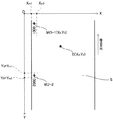
図2(b)に示すように、マークMは、面原点MOと面番号MNとの組合せにより構成される。面番号MNは、一つ目にマーキングされる面番号MNを「0001」とし、以降、「0002」、「0003」、…、と「1」ずつ加算された連番となる。また、本実施形態においては、処理対象の面が切り替わるようになっており、各面は面番号MNの示す数字によって特定される。例えば、図3の斜線部で示すように、面番号MN「0001」で特定される面Pは、面原点MO−1を通る線L−1と、面原点MO−2を通る線L−2で区切られる領域となる。また、現在処理対象の面が面番号MN「0001」で特定される面Pである場合には、次に処理対象となる面は面番号MN「0002」で特定される面(すなわち、面原点MO−2を通る線L−2と、面原点MO−3を通る線L−3で区切られる領域)となる。 As shown in FIG. 2B, the mark M is composed of a combination of a surface origin MO and a surface number MN. The surface number MN is a serial number in which the surface number MN to be marked first is “0001” and “0002”, “0003”,. In the present embodiment, the surfaces to be processed are switched, and each surface is specified by a number indicated by the surface number MN. For example, as indicated by the hatched portion in FIG. 3, the surface P identified by the surface number MN “0001” is composed of a line L-1 passing through the surface origin MO-1 and a line L-2 passing through the surface origin MO-2. It becomes an area delimited by. If the current processing target surface is the surface P specified by the surface number MN “0001”, the next processing target surface is the surface specified by the surface number MN “0002” (ie, the surface origin). (A region divided by a line L-2 passing through MO-2 and a line L-3 passing through the plane origin MO-3).
本実施形態では、シート材Sを図示しない搬送ローラで搬送しつつ、裏面から蛍光灯13により照らされたシート材Sの表面をラインセンサカメラ12により撮影する。このとき、撮影画像は、欠陥DとマークMを含む画像となる。そして、撮影画像から、欠陥Dの位置を示す欠陥座標(Xd,Yd)を、搬送方向にある最寄りの面原点MOを基準とするナンバリング基準欠陥座標(Xn,Yn)に変換する。そして、ナンバリング基準欠陥座標(Xn,Yn)と、変換時に基準とした面原点MOと組をなす面番号MNを付加した情報を、欠陥位置情報とする。これにより、検査官は欠陥Dの位置を特定する際、まず、欠陥位置情報に含まれる面番号MNから欠陥Dが含まれる面を特定し、次いで、当該面にマーキングされた面原点MOを基準にナンバリング基準欠陥座標(Xn,Yn)の示す位置を探すことで、欠陥Dの位置を特定することができる。
In the present embodiment, the
[2.欠陥検査システム100の構成]
図4に示すように、欠陥検査システム100は、欠陥位置特定装置1と、サーバ装置2と、欠陥確認用端末3と、を有する。欠陥検査システム100においては、欠陥位置特定装置1が、シート材Sにおける欠陥Dの位置を特定するための欠陥位置情報を生成し、サーバ装置2に送信する。サーバ装置2は、受信した欠陥位置情報を記憶し、検査官が欠陥Dを確認(レビュー)する際に、当該記憶した欠陥位置情報を欠陥確認用端末3に送信する。欠陥確認用端末3は、検査官が欠陥Dの位置を特定できるように、サーバ装置2から受信した欠陥位置情報を表示部に表示させる。
[2. Configuration of defect inspection system 100]
As shown in FIG. 4, the
[2.1.欠陥位置特定装置1の構成]
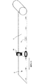
欠陥位置特定装置1は、制御部11、ラインセンサカメラ12、蛍光灯13、搬送ローラ14、ロータリーエンコーダ15、IJマーカー16、通信部17、及び記憶部18を備えている。
[2.1. Configuration of Defect Position Identification Device 1]
The defect
ラインセンサカメラ12は、制御部11の制御により、シート材S表面を1ラインずつ連続的に撮影し、撮影画像を制御部11に送信する。制御部11は、撮影画像を記憶部18に記憶させ、各画像をつなぎ合わせて2次元の撮影画像を形成する。蛍光灯13は、ラインセンサカメラ12と対向する位置に設置され、シート材Sを背面から照らすようになっている。搬送ローラ14は、制御部11の制御により、ロール状に巻かれたシート材Sを搬送方向に搬送する。ロータリーエンコーダ15は、制御部11の制御により、搬送ローラ14の回転角度に基づいて、制御部11がシート材Sの搬送距離を算出するためのパルスを出力する。IJマーカー16は、制御部11の制御により、マークMを所定間隔毎にインクによりマーキングする。このとき、制御部11は、ロータリーエンコーダ15から出力されたパルスを計数し、所定距離の搬送が行われたかを判定する。通信部17は、サーバ装置2との間でデータを送受信するための制御等を行う。
The
記憶部18は、例えば、HDD(Hard disk drive)等により構成されており、オペレーティングシステムや、アプリケーションプログラム等の各種プログラムを記憶する。特に、本実施形態の記憶部18には、欠陥位置情報を生成するための各種処理を実行するアプリケーションプログラムが記憶されている。なお、各種プログラムは、例えば、他のサーバ装置等からネットワークを介して取得されるようにしても良いし、記録媒体に記録されて外付けドライブ装置を介して読み込まれるようにしても良い。
The
制御部11は、演算機能を有するCPU(Central Processing Unit)、ROM(Read Only Memory)、作業用のRAM(Random Access Memory)、及び図示しない発振回路等を備えて構成されており、操作部からの操作信号に基づいて、当該操作信号に含まれている操作情報に対応する動作を実現すべく上記各構成部材を制御するための情報を生成し、当該情報を該当する構成部材に出力して当該各構成部材の動作を統轄制御する。
The
[2.2.欠陥位置情報について]
次いで、欠陥位置特定装置1により生成され、サーバ装置2に記憶される欠陥位置情報について説明する。ここでは、図5に示すように、面番号MN「0001」の面が現在処理対象であって、当該面に欠陥Dが存在する場合において、原点O(0,0)を基準とする原点基準欠陥座標Dd(Xd,Yd)を、面原点MOを基準とするナンバリング基準欠陥座標Dn(Xn,Yn)に変換する場合について説明する。
[2.2. About defect location information]
Next, defect position information generated by the defect
図5に示すように、ラインセンサカメラ12より撮影された2次元の撮影画像における所定位置を原点O(0,0)とする。また、現在処理対象の面における面原点MO−1の重心(十字の中心部)座標を面原点座標MO−1(X0,Y0)とする。
As shown in FIG. 5, a predetermined position in a two-dimensional captured image captured by the
撮影画像において、マークMの幅方向(X軸方向)における位置を特定できるように、Xm1及びXm2の値が設定される。すなわち、マークMが「Xm1」〜「Xm2」の範囲にマーキングされるように、IJマーカー16はマークMをマーキングする。これにより、制御部11はXm1及びXm2を用いて、撮影画像におけるマークMを、欠陥Dと識別することができるようになっている。
In the captured image, the values of X m1 and X m2 are set so that the position of the mark M in the width direction (X-axis direction) can be specified. That is, the
また、次に処理対象となる面におけるマークMの面原点MO−2の搬送方向(Y軸方向)における位置を特定できるように、現在処理対象である面におけるマークMの面原点MO−1の座標Y0を基準とする、Ym1及びYm2の値が設定される。すなわち、次に処理対象となる面におけるマークMの面原点MO−2が「Y0+Ym1」〜「Y0+Ym2」の範囲にマーキングされるように、IJマーカー16は所定の間隔を開けてマークMをマーキングする。これにより、制御部11はYm1及びYm2を用いて、次に処理対象となる面におけるマークMの面原点MO−2と面番号MNとを識別することができるようになっている。
Further, the position of the surface origin MO-1 of the mark M on the surface to be processed is specified so that the position in the transport direction (Y-axis direction) of the surface origin MO-2 of the mark M on the surface to be processed next can be specified. The values of Y m1 and Y m2 are set with reference to the coordinate Y 0 . That is, the
なお、一番目の面(面番号MN「0001」の面)における面原点MO−1のY軸方向の位置については、座標を用いて特定することができない。つまり、「Xm1」〜「Xm2」の範囲にある欠陥Dを面原点MO−1と判定してしまうおそれがある。そこで、少なくとも一番目の面について面原点MO−1の位置を特定する際には、面原点MOの面積や縦横寸法を判定要素として加えることとする。このとき、面原点MOの大きさを一般的な欠陥の大きさよりも十分大きくするとともに、判定基準としてこれらの欠陥を除外でき、且つ、面原点MOの大きさが含まれる値を設定することとする。また、二番目以降の面における面原点MOの位置の特定についても、面原点MOの面積や縦横寸法を判定要素として加えることとすれば、誤って面原点MOの位置を特定する可能性を減らすことができる。 The position in the Y-axis direction of the surface origin MO-1 on the first surface (surface with surface number MN “0001”) cannot be specified using coordinates. That is, there is a possibility that the defect D in the range of “X m1 ” to “X m2 ” is determined as the plane origin MO-1. Therefore, when specifying the position of the surface origin MO-1 for at least the first surface, the area and vertical and horizontal dimensions of the surface origin MO are added as determination elements. At this time, the size of the surface origin MO is made sufficiently larger than the size of a general defect, and these defects can be excluded as a criterion, and a value including the size of the surface origin MO is set. To do. In addition, regarding the specification of the position of the surface origin MO on the second and subsequent surfaces, if the area and vertical and horizontal dimensions of the surface origin MO are added as determination elements, the possibility of specifying the position of the surface origin MO by mistake is reduced. be able to.
制御部11は、図5に示すように、欠陥Dが面番号MN「0001」の面に存在する場合には、面番号MN「0001」に対応する面原点MO−1の座標MO−1(X0,X0)を基準とするナンバリング基準欠陥座標Dnを算出する。具体的には、制御部11は、(式1)によって、ナンバリング基準欠陥座標Dn(Xn,Xn)を算出する。
(Xn,Yn)=(Xd−X0,Yd−Y0) (式1)
制御部11は、算出したナンバリング基準欠陥座標Dn(Xn,Xn)を示す欠陥座標情報と、現在処理対象である面の面番号MN「0001」を示す面番号情報とを含む欠陥位置情報を生成する。また、本実施形態の制御部11は、更に、欠陥Dが写っている部分を含むようにトリミング処理した撮影画像(「トリミング処理済み撮影画像」)を欠陥位置情報とする。すなわち、本実施形態における欠陥位置情報は、面番号、ナンバリング基準欠陥座標及びトリミング処理済み撮影画像からなる。これにより、検査官は、面番号及びナンバリング基準欠陥座標に基づいて欠陥Dを文字情報として把握することができるとともに、欠陥位置情報に含まれるトリミング処理済み撮影画像から欠陥Dを映像情報として把握することができる。
As shown in FIG. 5, when the defect D exists on the surface having the surface number MN “0001”, the
(X n , Y n ) = (X d −X 0 , Y d −Y 0 ) (Formula 1)
The
[2.3.サーバ装置2の構成]
図4に示すように、サーバ装置2は、制御部21、記憶部22、及び通信部23を備えている。通信部23は、欠陥位置特定装置1又は欠陥確認用端末3との間でデータを送受信するための制御等を行う。
[2.3. Configuration of server device 2]
As illustrated in FIG. 4, the
記憶部22は、例えば、HDD等により構成されており、オペレーティングシステムや、アプリケーションプログラム等の各種プログラムを記憶する。なお、各種プログラムは、例えば、他のサーバ装置等からネットワークを介して取得されるようにしても良いし、記録媒体に記録されて外付けドライブ装置を介して読み込まれるようにしても良い。また、記憶部22は、欠陥位置特定装置1から受信した欠陥位置情報を記憶する。
The
制御部21は、演算機能を有するCPU、ROM、作業用のRAM、及び図示しない発振回路等を備えて構成されており、操作部からの操作信号に基づいて、当該操作信号に含まれている操作情報に対応する動作を実現すべく上記各構成部材を制御するための情報を生成し、当該情報を該当する構成部材に出力して当該各構成部材の動作を統轄制御する。
The
[2.4.欠陥確認用端末3の構成]
欠陥確認用端末3は、制御部31、記憶部32、通信部33、搬送ローラ34、モニタカメラ35、操作部36、及び表示部37を備えている。欠陥確認用端末3は、検査官が欠陥位置特定装置1により生成された欠陥位置情報を参照しながら、シート材Sにおける欠陥Dを確認(レビュー)する際に使用される。
[2.4. Configuration of defect confirmation terminal 3]
The
記憶部32は、例えば、HDD等により構成されており、オペレーティングシステムや、アプリケーションプログラム等の各種プログラムを記憶する。なお、各種プログラムは、例えば、他のサーバ装置等からネットワークを介して取得されるようにしても良いし、記録媒体に記録されて外付けドライブ装置を介して読み込まれるようにしても良い。また、記憶部32は、サーバ装置2から受信した欠陥位置情報を記憶する。
The
通信部33は、サーバ装置2との間でデータを送受信するための制御等を行う。搬送ローラ34は、制御部31の制御の下、欠陥位置特定装置1によりマークMがマーキングされたシート材Sを巻き直したものを搬送方向に搬送する。モニタカメラ35は、図6に示すように、搬送中のシート材SにおけるマークMがマーキングされている領域を連続的に撮影し、撮影画像を制御部31に送信する。制御部31は、画像認識技術を用いてモニタカメラ35により撮影された撮影画像中に、欠陥位置情報に含まれる面番号情報の示す面番号(すなわち、欠陥Dを含む面を示す面番号)と同じ面番号MNが含まれているか否かを判定する。制御部31は、同じ面番号MNが含まれていると判定した場合には、搬送ローラ34を停止させ、検査官が欠陥Dを確認できるようにする。このとき、表示部37には、ナンバリング基準欠陥座標Dn(Xn,Xn)、面番号、及びトリミング処理済み撮影画像が表示される。
The
操作部36は、検査官による各種操作を受け付け、操作に応じた操作信号を制御部31に送信する。表示部37は、各種操作画面等を表示する。また、表示部37は欠陥位置情報に含まれる面番号、ナンバリング基準欠陥座標Dn及びトリミング処理済み撮影画像を表示する。
The
制御部31は、演算機能を有するCPU、ROM、作業用のRAM、及び図示しない発振回路等を備えて構成されており、操作部からの操作信号に基づいて、当該操作信号に含まれている操作情報に対応する動作を実現すべく上記各構成部材を制御するための情報を生成し、当該情報を該当する構成部材に出力して当該各構成部材の動作を統轄制御する。
The
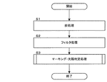
次に、図7に示すフローチャートを用いて、欠陥位置特定装置1の制御部11による欠陥位置特定処理について説明する。なお、本実施形態において制御部11は、ラインセンサカメラ12により撮影された撮影画像に基づいて、全面分の2次元撮影画像が形成された後に欠陥位置特定処理を実行する。但し、制御部11は2次元撮影画像を形成しつつ、並行して欠陥位置特定処理を行うこととしてもよい。
Next, the defect position specifying process by the
まず、欠陥位置特定装置1の制御部11は、ラインセンサカメラ12により撮影された撮影画像に基づいて形成した2次元撮影画像に対して前処理を行う(ステップS1)。具体的には、制御部11は、ノイズの除去や、シェーディング補正(光学系や撮像系の特性による輝度ムラに対して、一様な明るさの画像になるように補正する処理)を行う。
First, the
次いで、制御部11は、2次元撮影画像に対してフィルタ処理を行う(ステップS2)。具体的には、制御部11は、平滑化処理(移動平均フィルタ処理等)や、エッジ抽出処理(sovelフィルタ処理、Prewittフィルタ処理等)などを行い、2次元撮影画像においてノイズを減らすとともに、欠陥Dを際立たせる。
Next, the
次いで、制御部11は、前処理(ステップS1)及びフィルタ処理(ステップS2)が施された2次元撮影画像について、図8を用いて後述するマーキング・欠陥判定処理を行い(ステップS3)、本フローチャートに示す処理を終了する。
Next, the
次に、図8に示すフローチャートを用いて、欠陥位置特定装置1の制御部11によるマーキング・欠陥判定処理について説明する。
Next, the marking / defect determination process by the
まず、欠陥位置特定装置1の制御部11は、現在処理対象である面から欠陥候補を取得する(ステップS11)。具体的には、制御部11は、例えば、シート材Sが暗色のシート材である場合には、予め設定された閾値を超える輝度を持つ部分を特定し、当該部分を欠陥候補として取得する。またこのとき、制御部11は、現在処理対象である面に複数の欠陥候補が存在する場合には、搬送方向に位置する(面原点MOに近い)欠陥候補から、順次取得する。
First, the
制御部11は、ステップS11の処理において、一つの欠陥候補を取得すると、次いで、欠陥候補の座標(Xd,Yd)について、「Xm1<Xd<Xm2」を満足しているか否かを判定する(ステップS12)。すなわち、制御部11は、「Xm1」及び「Xm2」を用いて、欠陥候補がマークMであるか否かを判定する。このとき、制御部11は、「Xm1<Xd<Xm2」を満足していないと判定した場合には(ステップS12:NO)、ステップS17の処理に移行する。
When the
一方、制御部11は、「Xm1<Xd<Xm2」を満足していると判定した場合には(ステップS12:YES)、次いで、欠陥候補の座標(Xd,Yd)について、「Y0+Ym1<Yd<Y0+Ym2」を満足しているか否かを判定する(ステップS13)。すなわち、制御部11は、欠陥候補が面原点MOであるか又は面番号MNであるかを判定する。このとき、制御部11は、「Y0+Ym1<Yd<Y0+Ym2」を満足していないと判定した場合には(ステップS13:NO)、当該欠陥候補を欠陥Dから除外し、ステップS22の処理に移行する。
On the other hand, when it is determined that “X m1 <X d <X m2 ” is satisfied (step S12: YES), the
一方、制御部11は、「Y0+Ym1<Yd<Y0+Ym2」を満足していると判定した場合には(ステップS13:YES)、当該欠陥候補を面原点MOと判定し(ステップS14)、現在処理対象である面番号を示すカウンタmに1を加算する(ステップS15)。但し、ステップS14において、制御部11は、一番目の面(面番号MN「0001」の面)における面原点MO−1を判定する場合には、上述したように面原点MOの面積や縦横寸法を判定することとする。次いで、制御部11は、面原点MOの重心位置を面原点座標(X0,Y0)とし(ステップS16)、ステップS22の処理に移行する。
On the other hand, when it is determined that “Y 0 + Y m1 <Y d <Y 0 + Y m2 ” is satisfied (step S13: YES), the
他方、制御部11は、ステップS12の処理において、「Xm1<Xd <Xm1」を満足していないと判定した場合には(ステップS12:NO)、次いで、欠陥判定処理を行う(ステップS17)。具体的には、制御部11は、欠陥候補の輝度(或いは濃度)、形状、及び面積等が、納品基準(良品基準)等に基づいて設定される設定値を超えているかを判定する。このとき、例えば、濃度が一定の濃度より濃い場合には、欠陥候補の面積が設定値より小さくても欠陥と判定することとしてもよい。逆に、濃度が一定の濃度より薄い場合には、欠陥候補の面積が設定値より大きくても欠陥と判定しないこととしてもよい。このように、判定基準は様々設定することができる。
On the other hand, when it is determined that “X m1 <X d <X m1 ” is not satisfied in the process of step S12 (step S12: NO), the
制御部11は、欠陥判定処理の結果、欠陥候補が欠陥であったか否かを判定し(ステップS18)、欠陥ではない(すなわち、納品基準(良品基準)に引っかからない)と判定した場合には(ステップS18:NO)、ステップS22の処理に移行する。一方、制御部11は、欠陥である(すなわち、納品基準(良品基準)に引っかかる)と判定した場合には(ステップS18:YES)、当該欠陥の欠陥座標(Xd,Yd)をナンバリング基準欠陥座標Dn(Xn,Yn)に変換する(ステップ19)。
As a result of the defect determination process, the
次いで、制御部11は、ナンバリング基準欠陥座標Dnを示す欠陥座標情報と、現在の面番号mを示す面番号情報と、トリミング処理済み撮影画像とを、含む欠陥位置情報を生成する(ステップ20)。なお、このとき、制御部11は、2次元撮影画像に対してトリミング処理を施す。
Next, the
次いで、制御部11は、欠陥位置情報をサーバ装置2に送信し(ステップS21)、ステップS22の処理に移行する。
Subsequently, the
ステップS22の処理では、制御部11は、欠陥候補を全て取得したか否かを判定する(ステップS22)。このとき、制御部11は、欠陥候補を全て取得したと判定した場合には(ステップS22:YES)、本フローチャートにおける処理を終了する。一方、制御部11は、欠陥候補を全て取得していないと判定した場合には(ステップS22:NO)、ステップS11の処理に移行し、次の欠陥候補を取得する。
In the process of step S22, the
以上説明したように、本実施形態の欠陥位置特定装置1(「欠陥位置情報生成装置」の一例)の制御部11(「撮影画像取得手段」、「特定手段」、「欠陥座標算出手段」、「欠陥位置情報生成手段」の一例)は、面原点MO(「原点」の一例)と、面原点MOを識別するための面番号MN(「記号」の一例)との組合せであるマークMが、長手方向(搬送方向)に複数マーキング(印字)されたシート材S(「長尺シート材」の一例)の撮影画像を取得し、当該取得した撮影画像において、面原点MO及び欠陥Dの位置を特定する。また、制御部11は、当該特定した面原点MOのうち現在処理対象である面に含まれる面原点MO(すなわち、欠陥Dより搬送方向にマーキングされた最寄りの面原点MO。「1番目又は2番目に近い原点」の一例)を基準として、当該特定した欠陥Dの位置を示すナンバリング基準欠陥座標Dnを算出し、このとき基準となった面原点MOと組合せをなす面番号MNを示す面番号情報(「記号情報」の一例)と、当該算出したナンバリング基準欠陥座標Dnを示す欠陥座標情報とを含む欠陥位置情報を生成する。
As described above, the control unit 11 (“captured image acquisition unit”, “identification unit”, “defect coordinate calculation unit”, defect position identification apparatus 1 (an example of “defect position information generation apparatus”) according to the present embodiment, An example of “defect position information generation means” includes a mark M that is a combination of a surface origin MO (an example of “origin”) and a surface number MN (an example of “symbol”) for identifying the surface origin MO. A photographed image of a sheet material S (an example of a “long sheet material”) that has been marked (printed) in the longitudinal direction (conveyance direction) is acquired, and the position of the surface origin MO and the defect D in the acquired photographed image Is identified. The
本実施形態の欠陥位置特定装置1によれば、シート材Sにマーキングされた面原点MOのうち、欠陥Dに1番目又は2番目に近い面原点MOを基準とするナンバリング基準欠陥座標を示す欠陥座標情報と、当該基準となった面原点MOと組合せをなす面番号MNを示す面番号情報と、を含む欠陥位置情報が生成される。したがって、欠陥箇所に直接マーキングされることはなく、検査官は、面番号情報の示す面番号MNと組合せをなす面原点MOを基準として、欠陥座標情報の示す位置を探すことにより、欠陥箇所を特定することができる。すなわち、検査官は、欠陥に近い面原点MOを基準に欠陥箇所を探すこととなるので、図1に示すように検査基準位置Oを基準に欠陥箇所を探す場合と比較して、すみやかに欠陥位置を特定することができる。
According to the defect
また、本実施形態において、面原点MO及び面番号MNは、シート材Sの幅方向における所定範囲内の位置に複数マーキングされ(図2(a)参照)、欠陥位置特定装置1の制御部11は、欠陥候補を取得し(図8のステップS11)、当該欠陥候補の位置が、2次元撮影画像において所定範囲を示す情報(「Xm1」、「Xm2」)により示される所定範囲(「Xm1」〜「Xm2」)内に含まれないと判定した場合に、当該欠陥候補を欠陥Dとして特定する。
In the present embodiment, the surface origin MO and the surface number MN are marked at a plurality of positions within a predetermined range in the width direction of the sheet material S (see FIG. 2A), and the
また、本実施形態において、各面原点MOは、シート材Sの幅方向における所定範囲内において、シート材Sの長手方向に所定間隔(例えば、1メートル)毎にマーキングされ(図2(a)参照)、欠陥位置特定装置1の制御部11は、欠陥候補を取得し(図8のステップS11)、当該特定した欠陥候補の位置が、撮影画像において所定範囲を示す情報(「Xm1」、「Xm2」)により示される所定範囲(「Xm1」〜「Xm2」)内に含まれると判定し、且つ、当該特定した欠陥候補の位置が、撮影画像において直前に特定した面原点MOから、所定間隔を示す情報(「Ym1」、「Ym2」)により示される所定距離とほぼ同じ距離にあると判定した場合に、当該欠陥候補を面原点MOとして新たに特定する。
In the present embodiment, each surface origin MO is marked at predetermined intervals (for example, 1 meter) in the longitudinal direction of the sheet material S within a predetermined range in the width direction of the sheet material S (FIG. 2A). The
また、本実施形態において、欠陥確認用端末3(「欠陥確認装置」の一例)は、欠陥位置特定装置1により欠陥位置情報が生成されたシート材Sを長手方向に搬送する搬送ローラ34(「搬送手段」の一例)と、搬送されるシート材Sにおける面番号MNがマーキングされた部分を撮影するモニタカメラ35(「印字部撮影手段」の一例)と、を備え、制御部31(「欠陥位置情報取得手段」、「搬送制御手段」の一例)は、欠陥位置特定装置1により生成された欠陥位置情報を取得し、当該取得した欠陥位置情報における面番号情報の示す面番号と同じ面番号MNが、モニタカメラ35により撮影された場合に、搬送ローラ34による搬送を停止させる。これにより、欠陥Dが含まれる面がモニタカメラ35により撮影される位置まで搬送されると自動停止するので、検査官は欠陥Dの確認を容易に行うことができる。
In the present embodiment, the defect confirmation terminal 3 (an example of “defect confirmation device”) conveys the sheet material S on which the defect position information is generated by the defect
なお、本実施形態においては、シート材Sにマーキングされる面原点MOをそれぞれ識別するために面番号MNが付されているが、これに代えて、文字や記号又はこれらの組合せを付することとしてもよい(例えば、「A−あ」、「A−い」、・・・、「Z−ん」)。但し、本実施形態の面番号MNのように数字を連番で付した方が、検査官が確認する際に確認しやすいと考えられる。 In the present embodiment, the surface number MN is assigned to identify the surface origin MO marked on the sheet material S, but instead of this, a character, a symbol, or a combination thereof is attached. (For example, “A-A”, “A-I”,..., “Z-N”). However, it is considered that it is easier for the inspector to confirm if the numbers are assigned consecutively, such as the surface number MN of the present embodiment.
また、マーキング・欠陥判定処理(図8参照)において、欠陥位置特定装置1の制御部11は、公知の画像認識技術(パターンマッチング)により、面原点MOの位置と、面番号MNの位置及び数値を特定することとしてもよい。すなわち、記憶部18に、パターンマッチング用の画像データ(面原点MOを表す画像データ、数字を表す画像データ等)を記憶させておき、ラインカメラ12により撮影された撮影画像と比較することにより、制御部11は、面原点MOの位置と、面番号MNの位置及び数値を特定することとしてもよい。
Further, in the marking / defect determination process (see FIG. 8), the
また、本実施形態の欠陥位置特定装置1は、輪転印刷機、シート材Sをコーティングするコーター、或いは巻き返し機の一部に適用することができる。
Moreover, the defect
また、本実施形態において、欠陥位置特定装置1の制御部11は、図3に示すように、欠陥Dの位置が面原点MO−1よりも面原点MO−2に近い場合であっても、処理対象となっている面Pの面原点MO−1を基準としてナンバリング基準欠陥座標を算出するが、欠陥Dから最寄りの面原点MO−2を基準としてナンバリング基準欠陥座標を算出することとしてもよい。この場合、図3の下方向をY軸の正方向とすれば、ナンバリング基準欠陥座標のY成分は負の値となる。
Further, in the present embodiment, the
1 欠陥位置特定装置
11 制御部
12 ラインセンサカメラ
13 蛍光灯
14 搬送ローラ
15 ロータリーエンコーダ
16 インクジェットマーカー
17 通信部
18 記憶部
2 サーバ装置
21 制御部
22 記憶部
23 通信部
3 欠陥確認用端末
31 制御部
32 記憶部
33 通信部
34 搬送ローラ
35 モニタカメラ
36 操作部
37 表示部
S シート材
D 欠陥
M マーク
MO 面原点
MN 面番号
DESCRIPTION OF
Claims (7)
原点と当該原点を識別するための記号との組合せが前記長手方向に複数印字された前記長尺シート材の撮影画像を取得する撮影画像取得手段と、
前記取得された撮影画像において、前記原点及び前記欠陥の位置を特定する特定手段と、
前記特定された原点のうち前記特定された欠陥の位置に1番目又は2番目に近い原点を基準として、当該特定された欠陥の位置を示す欠陥座標を算出する欠陥座標算出手段と、
前記基準となった原点と前記組合せをなす前記記号を示す記号情報と、前記算出された欠陥座標を示す欠陥座標情報とを含む前記欠陥位置情報を生成する欠陥位置情報生成手段と、
を備えることを特徴とする欠陥位置情報生成装置。 A defect position information generating device that generates defect position information indicating a position of a defect in a long sheet material conveyed in a longitudinal direction,
Captured image acquisition means for acquiring a captured image of the long sheet material in which a plurality of combinations of an origin and a symbol for identifying the origin are printed in the longitudinal direction;
In the acquired captured image, specifying means for specifying the origin and the position of the defect;
A defect coordinate calculation means for calculating a defect coordinate indicating the position of the specified defect with reference to the first or second closest origin to the position of the specified defect among the specified origin;
Defect position information generating means for generating the defect position information including symbol information indicating the symbol that forms the combination with the reference origin, and defect coordinate information indicating the calculated defect coordinates;
A defect position information generating apparatus comprising:
前記記号は数字であり、前記長尺シート材の長手方向に連番となるように印字されていることを特徴とする欠陥位置情報生成装置。 The defect position information generation device according to claim 1,
The defect position information generating apparatus, wherein the symbol is a number and is printed so as to be a serial number in a longitudinal direction of the long sheet material.
前記原点及び前記記号は、前記長尺シート材の幅方向における所定範囲内に複数印字され、
前記特定手段は、
前記取得された撮影画像における欠陥候補を特定し、
前記特定した欠陥候補の位置が、前記取得された撮影画像において前記所定範囲を示す情報により示される当該所定範囲内に含まれないと判定した場合に、当該特定した欠陥候補を前記欠陥として特定することを特徴とする欠陥位置情報生成装置。 The defect position information generation device according to claim 1 or 2,
A plurality of the origin and the symbol are printed within a predetermined range in the width direction of the long sheet material,
The specifying means is:
Identify defect candidates in the acquired captured image,
When it is determined that the position of the identified defect candidate is not included in the predetermined range indicated by the information indicating the predetermined range in the acquired captured image, the identified defect candidate is identified as the defect. A defect position information generation apparatus characterized by the above.
各前記原点は、前記長尺シート材の幅方向における所定範囲内において、前記長尺シート材の長手方向に所定間隔毎に印字され、
前記特定手段は、
前記取得された撮影画像における欠陥候補を特定し、
前記特定した欠陥候補の位置が、前記取得された撮影画像において前記所定範囲を示す情報により示される当該所定範囲内に含まれると判定し、且つ、
前記特定した欠陥候補の位置が、前記取得された撮影画像において直前に特定した原点から、前記所定間隔を示す情報により示される当該所定距離とほぼ同じ距離にあると判定した場合に、当該欠陥候補を前記原点として特定することを特徴とする欠陥位置情報生成装置。 The defect position information generation device according to any one of claims 1 to 3,
Each origin is printed at predetermined intervals in the longitudinal direction of the long sheet material within a predetermined range in the width direction of the long sheet material,
The specifying means is:
Identify defect candidates in the acquired captured image,
Determining that the position of the identified defect candidate is included in the predetermined range indicated by the information indicating the predetermined range in the acquired captured image; and
When it is determined that the position of the specified defect candidate is substantially the same distance as the predetermined distance indicated by the information indicating the predetermined interval from the origin specified immediately before in the acquired captured image, the defect candidate Is specified as the origin, and the defect position information generating apparatus is characterized.
前記原点と前記記号との組合せが複数印字された前記長尺シート材を撮影する撮影手段を、
更に備えることを特徴とする欠陥位置情報生成装置。 The defect position information generation device according to any one of claims 1 to 4,
A photographing means for photographing the long sheet material on which a plurality of combinations of the origin and the symbol are printed,
A defect position information generation device further comprising:
前記欠陥確認装置は、
前記欠陥位置情報生成装置により生成された前記欠陥位置情報を取得する欠陥位置情報取得手段と、
前記欠陥位置情報生成装置により前記欠陥位置情報が生成された前記長尺シート材を長手方向に搬送する搬送手段と、
前記搬送される長尺シート材における前記記号が印字された部分を撮影する印字部撮影手段と、
前記取得された欠陥位置情報における記号情報の示す記号と同じ記号が、前記印字部撮影手段により撮影された場合に、前記搬送手段による搬送を停止させる搬送制御手段と、
を備えることを特徴とする欠陥確認システム。 A defect confirmation system comprising the defect position information generation device according to any one of claims 1 to 5 and a defect confirmation device,
The defect checking device is
Defect position information acquisition means for acquiring the defect position information generated by the defect position information generation device;
Conveying means for conveying the long sheet material in which the defect position information is generated by the defect position information generating device in a longitudinal direction;
A printing unit photographing means for photographing a portion on which the symbol is printed in the conveyed long sheet material;
A conveyance control unit that stops conveyance by the conveyance unit when the same symbol as the symbol information in the acquired defect position information is photographed by the printing unit photographing unit;
A defect confirmation system comprising:
原点と当該原点を識別するための記号との組合せが前記長手方向に複数印字された前記長尺シート材の撮影画像を取得する撮影画像取得工程と、
前記取得された撮影画像において、前記原点及び前記欠陥の位置を特定する特定工程と、
前記特定された原点のうち前記特定された欠陥の位置に1番目又は2番目に近い原点を基準として、当該特定された欠陥の位置を示す欠陥座標を算出する欠陥座標算出工程と、
前記基準となった原点と前記組合せをなす前記記号を示す記号情報と、前記算出された欠陥座標を示す欠陥座標情報とを含む前記欠陥位置情報を生成する欠陥位置情報生成工程と、
を含むことを特徴とする欠陥位置情報生成方法。 A defect position information generation method by a defect position information generation device that generates defect position information indicating a position of a defect in a long sheet material conveyed in the longitudinal direction,
A captured image acquisition step of acquiring a captured image of the long sheet material in which a plurality of combinations of an origin and a symbol for identifying the origin are printed in the longitudinal direction;
In the acquired captured image, a specifying step for specifying the origin and the position of the defect;
A defect coordinate calculation step of calculating defect coordinates indicating the position of the specified defect with reference to the first or second closest origin to the position of the specified defect among the specified origin;
A defect position information generating step for generating the defect position information including symbol information indicating the symbol that forms the combination with the reference origin, and defect coordinate information indicating the calculated defect coordinates;
A defect position information generation method comprising:
Priority Applications (1)
| Application Number | Priority Date | Filing Date | Title |
|---|---|---|---|
| JP2011070671A JP2012202957A (en) | 2011-03-28 | 2011-03-28 | Defect position information generation device, defect confirmation system, and defect position information generation method |
Applications Claiming Priority (1)
| Application Number | Priority Date | Filing Date | Title |
|---|---|---|---|
| JP2011070671A JP2012202957A (en) | 2011-03-28 | 2011-03-28 | Defect position information generation device, defect confirmation system, and defect position information generation method |
Publications (1)
| Publication Number | Publication Date |
|---|---|
| JP2012202957A true JP2012202957A (en) | 2012-10-22 |
Family
ID=47184103
Family Applications (1)
| Application Number | Title | Priority Date | Filing Date |
|---|---|---|---|
| JP2011070671A Withdrawn JP2012202957A (en) | 2011-03-28 | 2011-03-28 | Defect position information generation device, defect confirmation system, and defect position information generation method |
Country Status (1)
| Country | Link |
|---|---|
| JP (1) | JP2012202957A (en) |
Cited By (3)
| Publication number | Priority date | Publication date | Assignee | Title |
|---|---|---|---|---|
| JP2019018958A (en) * | 2017-07-14 | 2019-02-07 | 凸版印刷株式会社 | Continuous sheet quality monitoring system |
| KR102221447B1 (en) * | 2019-09-24 | 2021-03-02 | 주식회사 커미조아 | Method and apparatus for detecting defects of plate |
| CN113570601A (en) * | 2021-09-24 | 2021-10-29 | 深圳新视智科技术有限公司 | Defect marking method and system |
-
2011
- 2011-03-28 JP JP2011070671A patent/JP2012202957A/en not_active Withdrawn
Cited By (3)
| Publication number | Priority date | Publication date | Assignee | Title |
|---|---|---|---|---|
| JP2019018958A (en) * | 2017-07-14 | 2019-02-07 | 凸版印刷株式会社 | Continuous sheet quality monitoring system |
| KR102221447B1 (en) * | 2019-09-24 | 2021-03-02 | 주식회사 커미조아 | Method and apparatus for detecting defects of plate |
| CN113570601A (en) * | 2021-09-24 | 2021-10-29 | 深圳新视智科技术有限公司 | Defect marking method and system |
Similar Documents
| Publication | Publication Date | Title |
|---|---|---|
| TWI506271B (en) | Method,system,and computer-readable storage medium for inspectiing a web | |
| US8238646B2 (en) | Apparatus and method for the automated marking of defects on webs of material | |
| JP2009053122A (en) | Visual inspection system for transparent film | |
| CN113390879A (en) | Coating measurement, correction and flaw detection method and system | |
| JP2017211325A (en) | Defect inspection method and defect inspection device | |
| JP2012202957A (en) | Defect position information generation device, defect confirmation system, and defect position information generation method | |
| JP2010025586A (en) | Configuration determination method and configuration determination apparatus | |
| JP2006292503A (en) | Method and device for flaw inspection | |
| JP2015166722A (en) | Defect image imaging device and defect image imaging method | |
| US20200116648A1 (en) | Cylindrical body surface inspection device and cylindrical body surface inspection method | |
| JP2013250190A (en) | Inspection method and inspection apparatus of printed matter | |
| JP6398950B2 (en) | Device for photographing the surface of a plate-like body | |
| JP5513069B2 (en) | Defect inspection apparatus and defect inspection method | |
| US8740061B2 (en) | Recording information for a web manufacturing process | |
| JP5889426B1 (en) | Web inspection device, web inspection method, web inspection program | |
| JP2011252886A (en) | Inspection method for printed matter and inspection device therefor | |
| JP5786631B2 (en) | Surface defect inspection equipment | |
| JP2015059854A (en) | Defect inspection method and defect inspection device | |
| JP2012083128A (en) | Learning type defect discrimination processing system, method, and program | |
| JP6225719B2 (en) | Straightness measuring device, straightness measuring method, and program | |
| JP6780533B2 (en) | Shape measurement system and shape measurement method | |
| JP2019178933A (en) | Defect inspection system and defect inspection method | |
| CN110989422A (en) | Management system and management method for AOI (automated optical inspection) over-inspection parameters based on serial number code spraying | |
| JP2020190485A (en) | Identification model generation device, identification model generation method and identification model generation program, and steel defect determination device, steel defect determination method and steel defect determination program | |
| TWI549097B (en) | A method of detecting images of appearance of electronic components and computer readable media thereof |
Legal Events
| Date | Code | Title | Description |
|---|---|---|---|
| A300 | Withdrawal of application because of no request for examination |
Free format text: JAPANESE INTERMEDIATE CODE: A300 Effective date: 20140603 |