JP2012201486A - Sheet conveying device, image forming apparatus, sheet skew correcting method, and program therefor - Google Patents
Sheet conveying device, image forming apparatus, sheet skew correcting method, and program therefor Download PDFInfo
- Publication number
- JP2012201486A JP2012201486A JP2011069971A JP2011069971A JP2012201486A JP 2012201486 A JP2012201486 A JP 2012201486A JP 2011069971 A JP2011069971 A JP 2011069971A JP 2011069971 A JP2011069971 A JP 2011069971A JP 2012201486 A JP2012201486 A JP 2012201486A
- Authority
- JP
- Japan
- Prior art keywords
- skew
- sheet
- amount
- correction
- conveying
- Prior art date
- Legal status (The legal status is an assumption and is not a legal conclusion. Google has not performed a legal analysis and makes no representation as to the accuracy of the status listed.)
- Withdrawn
Links
Images
Abstract
Description
本発明は、シート搬送装置及び画像形成装置、シート斜行補正方法、並びにプログラムに関し、特に、複写機やプリンタにおいて、画像形成部に搬送されるシートの斜行補正の技術に関する。 The present invention relates to a sheet conveying device, an image forming apparatus, a sheet skew correction method, and a program, and more particularly to a technique for correcting skew of a sheet conveyed to an image forming unit in a copying machine or a printer.
従来、複写機、プリンタ、ファクシミリ等の画像形成装置では、画像形成部にシートを搬送するシート搬送装置を備える。シート搬送装置には、画像形成部に搬送するまでにシートの姿勢や位置を合わせるために、シートの斜行を補正するための斜行補正部を備えたものがある。斜行補正部のシートの斜行補正には、レジストローラ対を用いてシートにループを形成することにより斜行を補正する方法があるが、この方法では、シートを一旦停止させるため、斜行補正に要する時間が長くなる。そこで、斜行補正に要する時間を縮めるために、2つのセンサと、それぞれ独立に回転する2つの斜行補正ローラとを用いてシートを搬送しながら旋回させることにより、斜行補正するアクティブレジスト方式がある(特許文献1参照)。 2. Description of the Related Art Conventionally, image forming apparatuses such as copying machines, printers, and facsimiles include a sheet conveying apparatus that conveys a sheet to an image forming unit. Some sheet conveying apparatuses include a skew correction unit for correcting skew of a sheet in order to adjust the posture and position of the sheet before being conveyed to the image forming unit. In the skew correction of the sheet in the skew correction unit, there is a method of correcting skew by forming a loop on the sheet using a pair of registration rollers. In this method, the sheet is temporarily stopped to temporarily stop the sheet. The time required for correction becomes longer. Therefore, in order to reduce the time required for the skew correction, an active registration system that corrects the skew by rotating the sheet while transporting it using two sensors and two skew correction rollers that rotate independently of each other. (See Patent Document 1).
このようなアクティブレジスト方式では、まずシートの先端が、シート搬送路にシート搬送方向に直交する直線線上に一定の間隔で配置された2つのセンサを横切ったときのセンサからのシート検知信号の時間差に基づいてシートの斜行量を算出する。そして、算出された斜行量に応じて左右2つの斜行補正ローラを駆動する2つの駆動モータの回転速度を独立に制御することにより、2つの斜行補正ローラのシート搬送速度をシートの斜行量に応じて変化させ、シートの斜行を補正する。具体的には、シートの斜行量に応じて一方の斜行補正ローラのシート搬送速度を他方の斜行補正ローラの搬送速度よりも遅くする(「斜行減速制御」という)かまたは速くする(「斜行増速制御」という)ことにより、シートの斜行を補正する。 In such an active registration method, first, the time difference of the sheet detection signal from the sensor when the leading edge of the sheet crosses two sensors arranged at regular intervals on a straight line orthogonal to the sheet conveying direction in the sheet conveying path. Based on the above, the skew amount of the sheet is calculated. Then, by independently controlling the rotational speeds of the two drive motors that drive the two left and right skew correction rollers according to the calculated skew amount, the sheet conveyance speed of the two skew correction rollers is adjusted to the sheet skew. Change according to the amount of lines to correct the skew of the sheet. Specifically, the sheet conveyance speed of one skew correction roller is made slower (called “skew deceleration control”) or faster than the conveyance speed of the other skew correction roller according to the sheet skew amount. (Referred to as “skew acceleration control”), the skew of the sheet is corrected.
このようにアクティブレジスト方式では、シートの搬送を一旦停止させることなく斜行補正を行うので、シート間隔(先行シートと後行シートの間隔)を他の方式に比べて狭くすることができる。これにより、シート搬送効率を高めることができ、例えば画像形成装置における画像形成のプロセス速度を上げることなく実質的な画像形成速度の向上を図ることができる。アクティブレジスト方式は、画像形成装置の画像形成動作の高速化に対応する技術である。 As described above, in the active registration method, the skew correction is performed without temporarily stopping the conveyance of the sheet, so that the sheet interval (the interval between the preceding sheet and the succeeding sheet) can be narrowed compared to other methods. Accordingly, the sheet conveyance efficiency can be increased, and for example, the substantial image forming speed can be improved without increasing the image forming process speed in the image forming apparatus. The active resist system is a technique that supports the speeding up of the image forming operation of the image forming apparatus.
また、近年は、様々な形状のシートに対する画像形成の需要が増大している中で、タブ付シートに対する要望が多くなっている。タブ付シートは、分類を目的として見出しなどを記入するためのタブ部を端辺に設けたシートである。 In recent years, demand for image formation on sheets having various shapes has increased, and there has been an increasing demand for sheets with tabs. The tabbed sheet is a sheet provided with a tab portion at the end for entering a headline or the like for classification.
しかしながら、タブ付シートのタブ部の位置は一定ではなく、タブ部に記入された見出しなどを確認し易いように、互いにずらして設けられている。このような形状のシートの斜行補正に対しては、シート形状の情報を斜行補正制御部に送信し、センサがタブ部分を検知するか否かによって、タブ幅の分だけセンサからの情報を補正して、斜行補正を実行する方式が提案されている(特許文献2参照)。 However, the position of the tab portion of the tabbed sheet is not constant, and is provided so as to be shifted from each other so that the headings and the like written in the tab portion can be easily confirmed. For skew correction of a sheet having such a shape, the sheet shape information is transmitted to the skew correction control unit, and information from the sensor corresponding to the tab width is determined depending on whether or not the sensor detects the tab portion. A method of correcting skew and executing skew correction has been proposed (see Patent Document 2).
しかしながら、上述した従来のタブ付シートに対する斜行補正では、タブの付いていない矩形シートであっても、シート形状の情報を斜行補正制御部に送らなければならず、結局、シート毎にシート形状の情報を送信することとなる。近年のシート搬送装置では、生産性向上のニーズに応えるべく、シートの搬送間隔が狭くなっているので、その送信レートも高くなることが予測され、CPUに対して複雑且つ高速な情報処理が要求される。 However, in the above-described skew correction for the tabbed sheet, the sheet shape information must be sent to the skew correction controller even for a rectangular sheet without a tab. Shape information is transmitted. In recent sheet conveying devices, the sheet conveying interval is narrowed to meet the need for improved productivity, so the transmission rate is expected to increase, and complex and high-speed information processing is required for the CPU. Is done.
また、タブ付シートは、その用途を踏まえると、矩形シートとの混載が当然考えられ、シート形状の情報の送信タイミングに関しても細かなケアがなされていないと、誤ったプリントを誘発しかねない。また、タブの位置によっては、シート端検知センサにタブの縁がかかってしまうことも想定される。このような場合、確実なシートの斜行補正が遂行できないおそれがある。 In addition, the tabbed sheet is naturally considered to be mixed with a rectangular sheet in view of its use, and if the care is not taken with regard to the transmission timing of the sheet shape information, erroneous printing may be induced. Further, depending on the position of the tab, it may be assumed that the edge of the tab is applied to the sheet edge detection sensor. In such a case, there is a possibility that reliable skew correction of the sheet cannot be performed.
本発明は、上記問題に鑑みて成されたものであり、タブ付シートと矩形シートの何れが給送されても、確実にシートの斜行補正を行うことができる技術を提供することを目的とするものである。 The present invention has been made in view of the above problems, and an object of the present invention is to provide a technique capable of reliably correcting the skew feeding of a sheet regardless of whether a tabbed sheet or a rectangular sheet is fed. It is what.
上記目的を達成するために、本発明のシート搬送装置は、シートを搬送する搬送手段と、シート搬送方向に直交する方向に沿って配置され、搬送されるシートを検知するための少なくとも4つのシート検知センサと、前記少なくとも4つのシート検知センサの位置からシート搬送方向の下流側にあって、前記シート搬送方向に直交する方向に沿って配置され、シートを搬送しながら斜行を補正するための斜行補正ローラと、前記少なくとも4つのシート検知センサから出力される検知信号の時間差から各センサ間毎にシートの斜行量を算出する斜行量算出手段と、前記斜行量算出手段により算出された斜行量から2つずつを組み合わせてそれぞれの差分を算出し、その差分が最小となる組み合わせの斜行量のうちいずれか一方を選択して補正斜行量とする斜行量選択手段と、前記補正斜行量を基に、前記斜行補正ローラの駆動を制御する駆動制御手段とを備えることを特徴とする。 In order to achieve the above object, a sheet conveying apparatus of the present invention includes a conveying unit that conveys a sheet, and at least four sheets that are arranged along a direction orthogonal to the sheet conveying direction and that detect the conveyed sheet. A detection sensor and a downstream side of the sheet conveyance direction from the position of the at least four sheet detection sensors, arranged along a direction orthogonal to the sheet conveyance direction, for correcting skew while conveying the sheet Calculated by the skew correction roller, the skew amount calculating means for calculating the skew amount of each sheet from the time difference between the detection signals output from the at least four sheet detection sensors, and the skew amount calculating means. Calculate the difference by combining two from each skew amount, and select one of the skew amounts of the combination that minimizes the difference and correct it. A skew amount selecting means and row weight, based on the correction amount of skew, characterized in that it comprises a drive control means for controlling the driving of the skew correcting roller.
本発明によれば、タブ付シートが搬送されても、タブ部分を検知しなかったセンサから得られる斜行量を基にタブの影響を受けない正確な斜行補正ができる。その結果、タブ付シート、矩形シートを予め判別することなく、確実にシートの斜行補正を行うことができる。 According to the present invention, even when a tabbed sheet is conveyed, accurate skew correction that is not affected by the tab can be performed based on the skew amount obtained from the sensor that did not detect the tab portion. As a result, the skew correction of the sheet can be reliably performed without discriminating between the tabbed sheet and the rectangular sheet in advance.
以下、本発明の実施の形態を図面を参照して詳細に説明する。 Hereinafter, embodiments of the present invention will be described in detail with reference to the drawings.
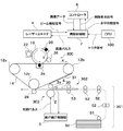
図1は、本発明の実施形態に係るシート搬送装置が適用された画像形成装置の概略構成を示す図である。 FIG. 1 is a diagram illustrating a schematic configuration of an image forming apparatus to which a sheet conveying apparatus according to an embodiment of the present invention is applied.
図1において、画像形成装置は、シート上に画像を形成する画像形成部300と、画像形成部300にシート30を給送するシート給送部301とを備える。画像形成部300には、感光ドラム16と、画像情報に基づいてレーザ光を照射して像担持体である感光ドラム上に静電潜像を形成するレーザースキャナ4とが設けられている。感光ドラム16は、不図示のモータにより駆動される。
In FIG. 1, the image forming apparatus includes an
レーザースキャナ4によるレーザ光の照射位置よりも感光ドラム16の回転方向の上流側には、感光ドラム16を一様に帯電させるための帯電器20が配置されている。一方、レーザ光の照射位置よりも感光ドラムの回転方向の下流側には、感光ドラム16上に形成された静電潜像をトナーによって現像し、トナー像を形成させる現像器22と、クリーナ26が配置されている。クリーナ26は、転写時に残留した転写残トナーを感光ドラム16から除去するためのクリーニングブレード等を有する。
A
さらに、画像形成部300には、感光ドラム16上のトナー像が転写される無端状の転写ベルト14と、転写ベルト14に張力を付与し、また当該転写ベルト14を回転駆動する3つのローラ12a〜12cが配置されている。ローラ12cと対向する位置には、転写ベルト14からシート30へトナー画像を転写するための2次転写ローラ28が設けられ、二次転写部を形成している。
Further, the
また、転写ベルト14を介して感光ドラム16と対向する位置には、感光ドラム16上から転写ベルト14へとトナー像31を転写するための一次転写帯電器24が配置され、一次転写部を形成している。
Further, a
シート給送部301は、記録用紙、OHPシートなどのシートを収容して不図示の装置本体に着脱自在なカセット50が設けられており、カセット50から給紙ローラ51により画像形成部300に向けてシート30が供給される。シート給送部301と画像形成部300との間には、シート給送部301から給送されたシート30を画像形成部300の二次転写部に搬送するシート搬送装置302が設けられている。
The
シート搬送装置302には、シート30の位置精度を高め、転写ベルト上のトナー像に合わせてシート30の斜行を補正して送り出す斜行補正部303が設けられている。シート搬送装置302において、搬送されるシートはシート搬送方向に直交する幅方向の中央を搬送規準(いわゆる中央規準)として搬送される。
The
画像制御部7は、レーザースキャナ4からレーザ光検知信号(ビーム検知信号)を受信すると共に、当該信号に同期してレーザースキャナ4に画像データに応じた画像パルスを送信する。レーザ光検知信号は、1走査ライン毎の画像の書き出しタイミングの基準となる同期信号であり、レーザースキャナ4に内蔵されたレーザ光を偏向するポリゴンミラー(不図示)で反射されたレーザ光がレーザ光検知センサ(不図示)で検知されたときに発せられる。
The image control unit 7 receives a laser light detection signal (beam detection signal) from the
コントローラ8は、画像形成装置の外部にあるパーソナルコンピュータ(PC)や画像形成装置が備えるリーダから送信される画像データを一時的に格納し、画像制御部7からの画像要求信号と、水平同期信号を基に、画像データを画像制御部7に送信する。なお、水平同期信号は、レーザースキャナ4に内蔵されたフォトセンサが出力するレーザ光検知信号を基に生成される。そして、画像要求信号を基準として所定数の水平同期信号がカウントされてから、コントローラ8は画像データを水平同期信号に同期させて、所定ライン数分ごとに画像制御部7に送信する。画像データは、画像制御部7において、そのデータレベルに応じたパルス幅を有する画像パルスに変換される。画像要求信号は、例えば、装置全体のシーケンスを行うCPU100のトリガ信号を画像制御部7が受信することによって生成される。
The
斜行補正部303は、それぞれが独立して駆動される斜行補正ローラ対2と、シートの先端の斜行を検知する検知部としてのセンサ部6とを備えている。斜行補正ローラ対2の各斜行補正ローラは、一部分が切欠き状態となっている。シートの搬送待機中は、その切欠き部が上を向いた位置で停止し、斜行補正ローラ対2と対向する位置に配置された従動ローラ2aとは離間関係となる。
The
また、斜行補正部303は、斜行補正ローラ対2の駆動を制御する斜行補正制御部9を備えている。
In addition, the
次に、図1の画像形成装置における画像形成動作について説明する。 Next, an image forming operation in the image forming apparatus of FIG. 1 will be described.
CPU100からトリガ信号を受信すると、画像制御部7は画像要求信号をコントローラ8に出力する。この画像要求信号によりコントローラ8は、画像データを水平同期信号に同期させて画像制御部7に送信する。
When receiving the trigger signal from the
次に、画像制御部7は、画像データに応じた画像パルスをレーザースキャナ4に送信する。次に、レーザースキャナ4は、この画像パルスに対応したレーザ光を、或は不図示の画像メモリからのデータに対応した画像データに基づいて変調されたレーザ光を、図中矢印Bの反時計方向に回転する感光ドラム16上に照射する。このとき、感光ドラム16は、予め帯電器20により帯電されており、レーザ光が照射されることによって静電潜像が形成され、次いで現像器22により静電潜像が現像され、トナー像が形成される。この後、感光ドラム上に形成されたトナー像は、一次転写部にて、一次転写帯電器24に印加される一次転写バイアス電圧の作用で転写ベルト14上に転写される。
Next, the image control unit 7 transmits an image pulse corresponding to the image data to the
一方、CPU100から発せられるトリガ信号に同期して、転写ベルト14上のトナー像31との位置が合うようなタイミングでカセット50から給紙ローラ51によりシート30が送り出される。この後、シート30は搬送ローラ52を経て、レジ前ローラ53に搬送される。各搬送ローラ52の近傍には、シートを検知するためのセンサ(不図示)が配置されており、センサによるシートの検知に基づき、CPU100は不図示の駆動制御部を介して搬送ローラ52を駆動する。
On the other hand, in synchronization with the trigger signal issued from the
次に、シート30は、レジ前ローラ53により斜行補正部303に搬送され、この斜行補正部303を通過する際、斜行が補正される。その後、シート30は、転写ベルト14上のトナー像31との位置が合うタイミングで、転写ベルト14と2次転写ローラ28とにより構成される二次転写部に送られる。
Next, the
二次転写部に送られたシート30は、二次転写ローラ28によりトナー像が転写された後、不図示の定着部に搬送される。定着部により加熱及び加圧されることにより、シート30に未定着転写画像が永久定着される。
After the toner image is transferred by the
次に、斜行補正部303におけるシート斜行補正動作について説明する。
Next, a sheet skew correction operation in the
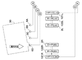
図2A及び図2Bは、図1の斜行補正部303と斜行補正制御部9の概略構成を示す図である。
2A and 2B are diagrams illustrating schematic configurations of the skew feeding
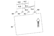
センサ部6は、図2Aに示すように、シートの搬送方向に直交する方向に沿って一定の間隔で配置された4つのシート検知センサ(以下、単に「センサ」とする)6A,6B,6C,6Dで構成されている。センサ6A〜6Dは、搬送路上を搬送されるシートの幅以内に収まるように配置され、搬送路上を搬送されるシートの端部を検知する。図2Aに示すような状態でタブ付のシート30が斜行している場合、センサ6D→6C→6B→6Aの順にシート端が検知される。センサ6A〜6Dから出力される検知信号は、斜行補正制御部9に入力される。
As shown in FIG. 2A, the
斜行補正ローラ対2は、シートの搬送方向に対して右側に配置された斜行補正ローラ2Rと、シートの搬送方向に対して左側に配置された斜行補正ローラ2Lとで構成される。斜行補正ローラ2Rは、モータ122Rにより独立して駆動され、斜行補正ローラ2Lは、モータ122Lにより独立して駆動される。モータ122Rは、ドライバ121Rを介して斜行補正制御部9に接続され、モータ122Lは、ドライバ121Lを介して斜行補正制御部9に接続されている。斜行補正動制御部9は、センサ6A〜6Dの検知信号をもとにシート30の斜行補正を制御するものである。
The skew
斜行補正ローラ2R,2Lには、不図示のマークが設けられており、不図示のホームポジションセンサが、このマークを検知すると、その検知信号が斜行補正制御部9内のモータパルス制御部120R,120Lに入力される。この検知信号に基づき、モータパルス制御部120R,120Lは、搬送待機時にドライバ121R,121Lを介してモータ122R,122Lを制御する。これにより、切欠き部が上を向く位置に、斜行補正ローラ2R,2Lを停止させることができる。
The
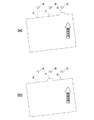
ここで、タブ付シートの斜行検知においてセンサを4つ設けることの優位性について図3を参照して説明する。 Here, the superiority of providing four sensors for detecting the skew of the tabbed sheet will be described with reference to FIG.
図3(a)と図3(b)は、3つのセンサでタブ付シートの斜行検知を行ったときの状態を示す図である。 FIGS. 3A and 3B are diagrams illustrating a state when the skew detection of the tabbed sheet is detected by the three sensors.
図3(a)及び図3(b)において、3つのセンサA,B,Cは、センサ6A〜6Dと同様に、シートの搬送方向と直交する方向に一定の間隔で配置されている。図3(a)に示すタブ付シートの場合、シートのタブ部分がセンサA〜CのうちセンサCの位置を通過する。図3(b)に示すタブ付シートの場合、シートのタブ部分がセンサA〜CのうちセンサBの位置を通過する。シート側のE,F,Gは、センサA〜Cによる被検知ポイントである。
3A and 3B, the three sensors A, B, and C are arranged at regular intervals in a direction orthogonal to the sheet conveyance direction, similarly to the
3つのセンサの間隔が同一であった場合、図3(a)に示すタブ付シートでは、FG間の斜行量が最も大きく、次にEG間の斜行量となり、タブ部分が存在しないEF間の斜行量が最小となる。この場合、シートの斜行補正に必要な斜行量はEF間の斜行量である。一方、図3(b)に示すタブ付シートでは、EF間の斜行量が最も大きく、次にEG間の斜行量となり、FG間の斜行量が最小となる。この場合、シートの斜行補正に必要な斜行量はEG間の斜行量である。 When the intervals of the three sensors are the same, in the sheet with tabs shown in FIG. 3A, the skew amount between FGs is the largest, then the skew amount between EGs, and there is no tab portion. The amount of skew in between is minimized. In this case, the skew amount necessary for correcting the skew of the sheet is the skew amount between EFs. On the other hand, in the tabbed sheet shown in FIG. 3B, the skew amount between EFs is the largest, then the skew amount between EGs, and the skew amount between FGs is the smallest. In this case, the amount of skew necessary for correcting the skew of the sheet is the amount of skew between the EGs.
本実施形態におけるタブ付シートの斜行検知方法は、シートのタブ付部分を検知したセンサに関する斜行検知情報を除外すべく、タブ部分を検知していないセンサが算出する近接した斜行量のグループを見極めるアリゴリズムを採用している。 The skew detection method for a tabbed sheet according to the present embodiment is based on the amount of adjacent skew calculated by a sensor that does not detect a tab portion so as to exclude skew detection information related to the sensor that detects the tabbed portion of the sheet. Adopting an algorithm that identifies the group.
図2Bに戻り、斜行補正制御部9は、モータパルス制御部120R,120L、斜行量検知部1000、斜行量換算部1001、差分算出部1002、比較部1003、斜行量選択部1004、及び速度算出部103R,103Lを備えている。
Returning to FIG. 2B, the skew
次に、斜行補正制御部9における斜行補正動作について図2A、図2B、図4、及び図5を参照して説明する。
Next, the skew correction operation in the
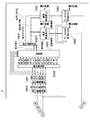
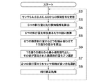
図4は、斜行補正制御部9における斜行補正動作の流れを示す図である。図5は、4つのセンサがタブ付のシート30を検知したときの斜行量(傾き)の比較例を示す図である。
FIG. 4 is a diagram illustrating a flow of the skew correction operation in the skew
信号待ち状態となっている斜行量検知部1000は、センサ6A〜6Dから検知信号を受信する(ステップS2)。
The skew
斜行量検知部1000は、受信した検知信号の時間差から、各センサ間毎のシートの斜行量を算出する(ステップS3)。ここで斜行量検知部1000は斜行量算出手段として機能する。本実施形態では、AB、AC、AD、BC、BD、CDの各センサ間のシートの斜行量が算出される。なお、シートの斜行量を、検知信号の時間差に加えて、シートの搬送速度と、4つのセンサの間隔とから求めるのが好適である。
The skew
また、ステップS3では、斜行量検知部1000は、任意の2つのセンサ間でどちらが先にシート端を検知したかを判定する。例えば、図中のアルファベット順で早い方のセンサが先行してシートを検知した場合に「1」、アルファベット順の遅い方のセンサが先行してシートを検知した場合には「0」とする。本実施形態では、これらの値を先行検知情報とする。斜行量検知部1000は、算出した6つの斜行量と、先行検知情報を斜行量換算部1001に送信する。本実施形態では、図2Bに示すように、AB間の斜行量と先行検知情報をAB、AC間の斜行量と先行検知情報をAC、AD間の斜行量と先行検知情報をAD、BC間の斜行量と先行検知情報をBCと称する。さらに、BD間の斜行量と先行検知情報をBD、CD間の斜行量と先行検知情報をCDと称する。
In step S3, the skew
次に、斜行量換算部1001は、斜行量検知部1000から受信した6つの斜行量を単位長さあたりの値に換算する(ステップSS4)。ここで斜行量換算部1001は斜行量換算手段として機能する。本実施形態では、ステップS4で換算された値を、図2Bに示すように、AB*、AC*、AD*、BC*、BD*、BD*、CD*と表現する。
Next, the skew
4つのセンサが50mm間隔で配置されている場合、最も距離の離れているAD間は150mmとなるので、単位長斜行換算部1001は、受信した6つの斜行量を150mmのセンサ間距離に換算する。即ち、50mm間隔のセンサから算出された斜行量は3倍され、100mm間隔のセンサから算出される斜行量は1.5倍される。換算後の値は、単位長斜行換算部1001から差分算出部1002に送信される。
When four sensors are arranged at intervals of 50 mm, the distance between the ADs farthest from each other is 150 mm. Therefore, the unit length
差分算出部1002は、換算後の6つ斜行量を組み合わせて、それらの差分を算出する(ステップS5)。ここでは、15通りの組み合わせから差分が算出される。15通りの差分情報は、差分算出部1002から比較部1003に送信される。本実施形態では、図2Bに示すように、例えば、AB*とAC*との差分をAB_ACと称する。この場合、先行検知情報が同一となる組み合わせでは、その差分は、大きい値から小さい値を差し引いたものとなり、先行検知情報が異なる組み合わせでは、その差分は双方を加算したものとなる。
The
図5に示すように、シートのタブ部分を検知するセンサ6Dを含む組合せA−D、B−D、C−Dの斜行量は、互いに異なり、同じものが無い。一方、センサ6Dを含まないA−B、A−C、B−Cは略同一となる。故に、差分AB_AC、AB_BC、AC_BCは略ゼロとなり、センサ6Dを含む残りの差分は、これら3つの差分よりも大きくなる。
As shown in FIG. 5, the skew feed amounts of the combinations AD, BD, and CD including the
次に、比較部1003は、15通りの差分情報を比較して最小がどれであるかを判断し、その最小の差分が算出された2つの換算斜行量を、斜行量1、斜行量2として選択する(ステップS6)。本実施形態では、最小と判断される差分はAB_AC、AB_BC、AC_BCのいずれかであるので、斜行量1、斜行量2として選択されるのは、AB*、AC*、BC*のいずれかである。このようにして、シートのタブ部分を検知したセンサ6D以外のセンサにより検出された斜行量が選択される。斜行量1、斜行量2は、比較部1003から斜行量選択部1004に送信される。
Next, the
斜行量選択部1004は、受信した斜行量1、斜行量2が得られたセンサの間隔の長い組の斜行量を選択して、補正斜行量として速度算出部103R,103Lに送信する(ステップS7)。また、斜行量選択部1004は、その斜行量に付随する先行検知情報を基に、先行フラグR,Lの値を決めて速度算出部103R,103Lに送信する。先行検知情報が「1」ならば先行フラグL=1、先行フラグR=0となる。先行検知情報が「0」ならば、先行フラグL=0、先行フラグR=1となる。本実施形態では、アルファベット順で遅い方のセンサが先行して検知するようにシートが傾いて搬送されているので、先行検知情報は「0」となり、先行フラグR=1、先行フラグL=0となる。
The skew amount selection unit 1004 selects a set of skew amounts having a long interval between the sensors from which the received
次に、ステップS8では、斜行補正処理が実行される。まず、速度算出部103Rは、受信した先行フラグRが「1」の場合、斜行補正ローラ2Rのシート搬送速度を定常速度V0から減速させる目標値となる目標速度V1を算出する。一方、速度算出部103Lは、受信した先行フラグLが「1」の場合、斜行補正ローラ2Lのシート搬送速度を定常速度V0から減速させる目標値となる目標速度V1を算出する。速度算出部103Rまたは103Lで算出された目標速度V1は、モータパルス制御部120Rまたは120Lに送信される。モータパルス制御部120R,120Lは、速度算出部103R,103Lから受信した目標速度V1に基づいて、モータ122R,122Lに与えるステップパルスの周期を制御することにより、斜行補正ローラ2R,2Lを目標速度V1で回転させる。
Next, in step S8, skew correction processing is executed. First, when the received preceding flag R is “1”, the
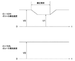
図6は、斜行補正時における斜行補正ローラ2R,2Lのシート搬送速度の変化の一例を示す図である。
FIG. 6 is a diagram illustrating an example of a change in the sheet conveyance speed of the
図2Aに示した状態でタブ付シートが搬送されていた場合、図6に示すように、斜行補正ローラ2Rが目標速度V1に減速制御され、斜行補正ローラ2Lは定常速度のまま回転させられる。目標速度V1の算出は、図4に示す変速域の台形の面積が斜行量と等しくなるように、設定された補正時間(実際の補正時間からV0からV1に移行する時間を差し引いた時間)で斜行量を除算して得られた減速幅を定常速度V0から差し引いて行う。そして、補正時間経過後、斜行補正ローラ2Rの速度がV1から再びV0に戻った時点で斜行補正処理が終了し、ステップS2に戻る。
When the tabbed sheet is conveyed in the state shown in FIG. 2A, as shown in FIG. 6, the
以上説明したように、本実施形態によれば、搬送されたシートがタブ付シートであっても、タブ部分を検知しなかったセンサから得られる斜行量を特定して、タブの影響を受けない正確な斜行補正が可能となる。その結果、タブ付シート、矩形シートを区別することなく、斜行補正を行うことができる。 As described above, according to the present embodiment, even if the conveyed sheet is a tabbed sheet, the skew amount obtained from the sensor that did not detect the tab portion is specified and affected by the tab. No accurate skew correction is possible. As a result, skew correction can be performed without distinguishing between tabbed sheets and rectangular sheets.
上記実施形態では、ステップS7において、斜行量選択部1004が、斜行量1、2からセンサ間隔の長い組の斜行量を補正斜行量として選択していたが、次のように選択してもよい。例えば、斜行量1と斜行量2の平均値((斜行量1+斜行量2)/2)を補正斜行量としてもよい。
In the above-described embodiment, in step S7, the skew amount selection unit 1004 selects a skew amount having a long sensor interval from the skew amounts 1 and 2 as the correction skew amount. May be. For example, an average value of the
また、本実施形態では、斜行検知するために4つのセンサ6A〜6Dを利用したが、5つ以上のセンサを利用してもよい。
Further, in the present embodiment, four
また、本発明は、以下の処理を実行することによっても実現される。即ち、上述した実施形態の機能を実現するソフトウェア(プログラム)を、ネットワーク又は各種記憶媒体を介してシステム或いは装置に供給し、そのシステム或いは装置のコンピュータ(またはCPUやMPU等)がプログラムを読み出して実行する処理である。 The present invention can also be realized by executing the following processing. That is, software (program) that realizes the functions of the above-described embodiments is supplied to a system or apparatus via a network or various storage media, and a computer (or CPU, MPU, or the like) of the system or apparatus reads the program. It is a process to be executed.
6A,6B,6C,6D センサ
9 斜行補正制御部
2R,2L 斜行補正ローラ
122R,122L モータ
1000 斜行量検知部
1001 斜行量換算部
1002 差分算出部
1003 比較部
1004 斜行量選択部
103R,103L 速度算出部
6A, 6B, 6C,
Claims (7)
シート搬送方向に直交する方向に沿って配置され、搬送されるシートを検知するための少なくとも4つのシート検知センサと、
前記少なくとも4つのシート検知センサの位置からシート搬送方向の下流側にあって、前記シート搬送方向に直交する方向に沿って配置され、シートを搬送しながら斜行を補正するための斜行補正ローラと、
前記少なくとも4つのシート検知センサから出力される検知信号の時間差から各センサ間毎にシートの斜行量を算出する斜行量算出手段と、
前記斜行量算出手段により算出された斜行量から2つずつを組み合わせてそれぞれの差分を算出し、その差分が最小となる組み合わせの斜行量のうちいずれか一方を選択して補正斜行量とする斜行量選択手段と、
前記補正斜行量を基に、前記斜行補正ローラの駆動を制御する駆動制御手段とを備えることを特徴とするシート搬送装置。 Conveying means for conveying the sheet;
At least four sheet detection sensors arranged along a direction orthogonal to the sheet conveyance direction and for detecting the conveyed sheet;
A skew correction roller that is disposed downstream of the position of the at least four sheet detection sensors in the sheet conveyance direction and is orthogonal to the sheet conveyance direction, and corrects skew while conveying the sheet. When,
A skew amount calculating means for calculating a skew amount of a sheet for each sensor from a time difference between detection signals output from the at least four sheet detection sensors;
The skew amount calculated by the skew amount calculation means is combined two by two to calculate each difference, and one of the combinations of skew amounts that minimizes the difference is selected and corrected skew Skew amount selection means as a quantity,
A sheet conveying apparatus comprising: drive control means for controlling driving of the skew feeding correction roller based on the correction skew feeding amount.
シート搬送方向に直交する方向に沿って配置され、搬送されるシートを検知するための少なくとも4つのシート検知センサと、
前記少なくとも4つのシート検知センサの位置からシート搬送方向の下流側にあって、前記シート搬送方向に直交する方向に沿って配置され、シートを搬送しながら斜行を補正するための斜行補正ローラと、
前記少なくとも4つのシート検知センサから出力される検知信号の時間差から各センサ間毎にシートの斜行量を算出する斜行量算出手段と、
前記斜行量算出手段により算出された斜行量から2つずつを組み合わせてそれぞれの差分を算出し、その差分が最小となる組み合わせの斜行量の平均値を補正斜行量とする斜行量選択手段と、
前記補正斜行量を基に、前記斜行補正ローラの駆動を制御する駆動制御手段とを備えることを特徴とするシート搬送装置。 Conveying means for conveying the sheet;
At least four sheet detection sensors arranged along a direction orthogonal to the sheet conveyance direction and for detecting the conveyed sheet;
A skew correction roller that is disposed downstream of the position of the at least four sheet detection sensors in the sheet conveyance direction and is orthogonal to the sheet conveyance direction, and corrects skew while conveying the sheet. When,
A skew amount calculating means for calculating a skew amount of a sheet for each sensor from a time difference between detection signals output from the at least four sheet detection sensors;
Skew that uses the skew amount calculated by the skew amount calculation means to calculate a difference between the two, and uses the average value of the skew amount of the combination that minimizes the difference as the corrected skew amount A quantity selection means;
A sheet conveying apparatus comprising: drive control means for controlling driving of the skew feeding correction roller based on the correction skew feeding amount.
シート搬送方向に直交する方向に沿って配置され、搬送されるシートを検知するための少なくとも4つのシート検知センサにより前記シートを検知する検知工程と、
前記少なくとも4つのシート検知センサの位置からシート搬送方向の下流側にあって、前記シート搬送方向に直交する方向に沿って配置され、シートを搬送しながら斜行を補正するための斜行補正ローラにより前記シートの斜行補正を行う斜行補正工程と、
前記少なくとも4つのシート検知センサから出力される検知信号の時間差から各センサ間毎にシートの斜行量を算出する斜行量算出工程と、
前記斜行量算出工程にて算出された斜行量から2つずつを組み合わせてそれぞれの差分を算出し、その差分が最小となる組み合わせの斜行量のうちいずれか一方を選択して補正斜行量とする斜行量選択工程と、
前記補正斜行量を基に、前記斜行補正ローラの駆動を制御する駆動制御工程とを備えることを特徴とするシート斜行補正方法。 In a sheet skew correction method of a sheet conveying apparatus including a conveying unit that conveys a sheet,
A detection step of detecting the sheet by at least four sheet detection sensors disposed along a direction orthogonal to the sheet conveyance direction and detecting the conveyed sheet;
A skew correction roller that is disposed downstream of the position of the at least four sheet detection sensors in the sheet conveyance direction and is orthogonal to the sheet conveyance direction, and corrects skew while conveying the sheet. A skew correction step for correcting the skew of the sheet,
A skew amount calculating step of calculating a skew amount of a sheet for each sensor from a time difference between detection signals output from the at least four sheet detection sensors;
By combining two skew amounts from the skew amount calculated in the skew amount calculation step, each difference is calculated, and one of the skew amounts in the combination that minimizes the difference is selected and corrected skew. A skew amount selection step as a line amount,
A sheet skew correction method comprising: a drive control step of controlling driving of the skew correction roller based on the correction skew amount.
シート搬送方向に直交する方向に沿って配置され、搬送されるシートを検知するための少なくとも4つのシート検知センサにより前記シートを検知する検知工程と、
前記少なくとも4つのシート検知センサの位置からシート搬送方向の下流側にあって、前記シート搬送方向に直交する方向に沿って配置され、シートを搬送しながら斜行を補正するための斜行補正ローラにより前記シートの斜行補正を行う斜行補正工程と、
前記少なくとも4つのシート検知センサから出力される検知信号の時間差から各センサ間毎にシートの斜行量を算出する斜行量算出工程と、
前記斜行量算出工程にて算出された斜行量から2つずつを組み合わせてそれぞれの差分を算出し、その差分が最小となる組み合わせの斜行量の平均値を補正斜行量とする斜行量選択工程と、
前記補正斜行量を基に、前記斜行補正ローラの駆動を制御する駆動制御工程とを備えることを特徴とするシート斜行補正方法。 In a sheet skew correction method of a sheet conveying apparatus including a conveying unit that conveys a sheet,
A detection step of detecting the sheet by at least four sheet detection sensors disposed along a direction orthogonal to the sheet conveyance direction and detecting the conveyed sheet;
A skew correction roller that is disposed downstream of the position of the at least four sheet detection sensors in the sheet conveyance direction and is orthogonal to the sheet conveyance direction, and corrects skew while conveying the sheet. A skew correction step for correcting the skew of the sheet,
A skew amount calculating step of calculating a skew amount of a sheet for each sensor from a time difference between detection signals output from the at least four sheet detection sensors;
A skew amount is calculated by combining two skew amounts calculated in the skew amount calculating step and calculating a difference between the two, and an average value of the skew amount of the combination that minimizes the difference is a corrected skew amount. A line quantity selection step;
A sheet skew correction method comprising: a drive control step of controlling driving of the skew correction roller based on the correction skew amount.
Priority Applications (1)
| Application Number | Priority Date | Filing Date | Title |
|---|---|---|---|
| JP2011069971A JP2012201486A (en) | 2011-03-28 | 2011-03-28 | Sheet conveying device, image forming apparatus, sheet skew correcting method, and program therefor |
Applications Claiming Priority (1)
| Application Number | Priority Date | Filing Date | Title |
|---|---|---|---|
| JP2011069971A JP2012201486A (en) | 2011-03-28 | 2011-03-28 | Sheet conveying device, image forming apparatus, sheet skew correcting method, and program therefor |
Publications (1)
| Publication Number | Publication Date |
|---|---|
| JP2012201486A true JP2012201486A (en) | 2012-10-22 |
Family
ID=47182857
Family Applications (1)
| Application Number | Title | Priority Date | Filing Date |
|---|---|---|---|
| JP2011069971A Withdrawn JP2012201486A (en) | 2011-03-28 | 2011-03-28 | Sheet conveying device, image forming apparatus, sheet skew correcting method, and program therefor |
Country Status (1)
| Country | Link |
|---|---|
| JP (1) | JP2012201486A (en) |
-
2011
- 2011-03-28 JP JP2011069971A patent/JP2012201486A/en not_active Withdrawn
Similar Documents
| Publication | Publication Date | Title |
|---|---|---|
| JP5201966B2 (en) | Image forming apparatus | |
| JP5623173B2 (en) | Sheet conveying apparatus, image forming apparatus, and image reading apparatus | |
| JP5721461B2 (en) | Image forming apparatus and control method thereof | |
| JP5967951B2 (en) | Sheet conveying apparatus, image reading apparatus using the same, and image forming apparatus | |
| JP4898518B2 (en) | Sheet conveying apparatus, image forming apparatus, and image reading apparatus | |
| JP5773725B2 (en) | Image forming apparatus | |
| JP2008065307A (en) | Image forming apparatus | |
| JP2007086726A (en) | Image printing apparatus | |
| JP5460222B2 (en) | Image forming apparatus and sheet conveying method | |
| JP2013053006A (en) | Sheet processing apparatus that detects displacement in sheet width direction and skew of sheet, and control method thereof | |
| JP2020183976A (en) | Image forming apparatus | |
| JP2016034860A (en) | Paper feeding device and image forming apparatus having the same | |
| JP5268545B2 (en) | Image forming apparatus | |
| JP2007031098A (en) | Sheet transporting device, image forming device, and image reading device | |
| JP2011248256A (en) | Image forming apparatus | |
| US20130134662A1 (en) | Sheet conveyance device | |
| JP7282499B2 (en) | Sheet conveying device and image forming device | |
| JP2011185976A (en) | Image forming apparatus | |
| JP2012201486A (en) | Sheet conveying device, image forming apparatus, sheet skew correcting method, and program therefor | |
| JP2012166956A (en) | Sheet conveying system and image forming apparatus, and image reader | |
| JP2012025544A (en) | Sheet conveying device and method of control thereof | |
| US8672321B2 (en) | Media path re-phasing | |
| US10534302B2 (en) | Image forming apparatus | |
| JP2010155677A (en) | Sheet carrying device and image forming device | |
| JP6390341B2 (en) | Sheet conveying apparatus, image forming apparatus, sheet characteristic estimating method, and sheet characteristic estimating program |
Legal Events
| Date | Code | Title | Description |
|---|---|---|---|
| A300 | Withdrawal of application because of no request for examination |
Free format text: JAPANESE INTERMEDIATE CODE: A300 Effective date: 20140603 |