JP2012201338A - Frictional resistance reduced ship and method for operating the same - Google Patents
Frictional resistance reduced ship and method for operating the same Download PDFInfo
- Publication number
- JP2012201338A JP2012201338A JP2011070615A JP2011070615A JP2012201338A JP 2012201338 A JP2012201338 A JP 2012201338A JP 2011070615 A JP2011070615 A JP 2011070615A JP 2011070615 A JP2011070615 A JP 2011070615A JP 2012201338 A JP2012201338 A JP 2012201338A
- Authority
- JP
- Japan
- Prior art keywords
- frictional resistance
- ship
- mixing chamber
- hull
- negative pressure
- Prior art date
- Legal status (The legal status is an assumption and is not a legal conclusion. Google has not performed a legal analysis and makes no representation as to the accuracy of the status listed.)
- Withdrawn
Links
Images


Classifications
-
- Y—GENERAL TAGGING OF NEW TECHNOLOGICAL DEVELOPMENTS; GENERAL TAGGING OF CROSS-SECTIONAL TECHNOLOGIES SPANNING OVER SEVERAL SECTIONS OF THE IPC; TECHNICAL SUBJECTS COVERED BY FORMER USPC CROSS-REFERENCE ART COLLECTIONS [XRACs] AND DIGESTS
- Y02—TECHNOLOGIES OR APPLICATIONS FOR MITIGATION OR ADAPTATION AGAINST CLIMATE CHANGE
- Y02T—CLIMATE CHANGE MITIGATION TECHNOLOGIES RELATED TO TRANSPORTATION
- Y02T70/00—Maritime or waterways transport
- Y02T70/10—Measures concerning design or construction of watercraft hulls
Abstract
Description
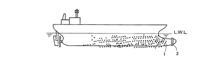
本発明は、微細気泡(マイクロバブル)を船体の外表面に供給して、船体と水との間の摩擦抵抗を低減した摩擦抵抗低減船およびその運転方法に関する。 The present invention relates to a frictional resistance-reducing ship in which fine bubbles (microbubbles) are supplied to the outer surface of a hull to reduce the frictional resistance between the hull and water and a method for operating the same.
船体の航行の妨げとなる抵抗には造波抵抗と摩擦抵抗がある。造波抵抗を低減する構造として球状船首(バルバス・バウ)が知られている。また、摩擦抵抗を低減する手段として微細気泡(マイクロバブル)を船体の外表面に供給する手段が知られている。 The resistance that hinders the navigation of the hull includes wave resistance and friction resistance. A spherical bow is known as a structure for reducing wave resistance. Further, as means for reducing frictional resistance, means for supplying fine bubbles (microbubbles) to the outer surface of the hull is known.
微細気泡を船体の外表面に供給する場合、出来るだけ船首に近い部分に供給することが摩擦を低減する上で有利である。斯かる内容は特許文献1に開示されている。
When supplying fine bubbles to the outer surface of the hull, it is advantageous for reducing friction to supply the fine bubbles to a portion as close to the bow as possible. Such contents are disclosed in
特許文献1に開示されている内容は、球状船首に穴を開け、この穴からコンプレッサで圧縮した空気を噴出すものである。気泡の径が小さいと水中での上昇速度が遅くなり、船体表面を包むようになり、摩擦抵抗の低減に有利となる。
しかしながら、特許文献1ではコンプレッサの圧力を利用して穴から噴出させているので気泡の径は大きい。噴出する気泡は破砕されてその径は小さくなるが船体表面の摩擦抵抗低減に効果的な気泡の径は1mm以下と言われており十分ではない。
The content disclosed in
However, in
微細気泡を発生する手段として、特許文献2に示すようなウィングを用いた構造が知られている。
この構造は、船体内側に空気と海水を混合するミックスチャンバーを設け、船の航行に伴ってウィングで負圧を発生せしめ、この負圧をミックスチャンバー内に作用させ、ミックスチャンバー内でケルビンーヘルムホルツ不安定現象(比重の大きな水が上になり比重の小さな空気が下になる現象)を起こさせ、この現象によって気泡を微細化し、これを船体表面に供給するものである。
As means for generating fine bubbles, a structure using wings as shown in
This structure is equipped with a mix chamber that mixes air and seawater inside the hull and generates negative pressure in the wing as the ship navigates. It causes an unstable phenomenon (a phenomenon where water with a large specific gravity rises and air with a low specific gravity falls), and this phenomenon refines the bubbles and supplies them to the hull surface.
前記したように特許文献1の構造では微細気泡を形成できない。またコンプレッサの圧力のみを利用して空気を噴出しているため、コンプレッサを駆動するための消費動力が大きくなり、省エネを十分達成することができない。
As described above, the structure of
一方、特許文献2に開示されるようにウィングを用いたタイプでは、微細気泡を発生でき且つコンプレッサが必要といってもそれはウィングで発生する負圧では気液界面を十分に押し下げることができない場合のアシストとして必要なだけであるので、大きな動力は必要とされず省エネの観点からも有利である。
On the other hand, the type using wings as disclosed in
しかしながら、ウィングを用いた構造では以下の問題が残されている。
先ず、ウィングは船体外側面より外側に露出しており、負圧が発生するウィング内側面(船体表面と対向する面)とミキシングチャンバーとの間には間隔が存在する。一方、ウィング内側の負圧が発生する領域は全ての方向に向かって開放されており、発生した負圧はミキシングチャンバーに対し集中的に作用するのではなく、周囲全体に均等に作用するため、負圧が発生しても瞬時に周りから負圧を解消する水が入り込み、負圧が有効にミキシングチャンバーに作用しにくい。
However, the following problems remain in the structure using wings.
First, the wing is exposed outside the hull outer surface, and there is a gap between the wing inner surface (surface facing the hull surface) where negative pressure is generated and the mixing chamber. On the other hand, the area where the negative pressure is generated inside the wing is open in all directions, and the generated negative pressure does not act intensively on the mixing chamber, but acts equally on the entire periphery. Even if negative pressure is generated, water that eliminates the negative pressure enters from the surroundings instantly, and it is difficult for the negative pressure to effectively act on the mixing chamber.
航行に伴って船体はピッチングする。このピッチングによってウィングを装着した部分も上下動する。ウィングが上下動すると負圧発生箇所もずれてしまい、効率よく気泡が形成されない。 The hull pitches as it sails. This pitching also causes the winged part to move up and down. When the wing moves up and down, the location where the negative pressure is generated shifts, and bubbles are not efficiently formed.
上記課題を解決するため本発明は、船体表面に微細気泡を供給することで摩擦抵抗を低減するようにした摩擦抵抗低減船であって、この摩擦抵抗低減船は球状船首を備え、この球状船首の外側に環状若しくは帯状のプレートを配置して前記球状船首外側面とプレート内側面との間に隙間を形成し、この隙間を隔壁部材によって複数の流路に区画し、各流路内には負圧を発生するための絞り部が設けられ、また前記球状船首の船体内側には気体供給源からの空気と海水とを混合するミキシングチャンバーが設けられ、前記流路の絞り部よりも下流側部分が前記ミキシングチャンバーと連通した構成とした。 In order to solve the above-described problems, the present invention provides a frictional resistance reduction ship that reduces frictional resistance by supplying fine bubbles to the hull surface, the frictional resistance reducing ship having a spherical bow, and the spherical bow. An annular or belt-like plate is disposed outside the inner surface to form a gap between the outer surface of the spherical bow and the inner surface of the plate, and the gap is divided into a plurality of flow paths by a partition member, A throttle part for generating negative pressure is provided, and a mixing chamber for mixing air and seawater from a gas supply source is provided inside the hull of the spherical bow, and downstream of the throttle part of the flow path. The portion was configured to communicate with the mixing chamber.
また、上記の摩擦抵抗低減船を運転する方法としては、ミキシングチャンバー内で気液の混合を行うために、船の航行速度および喫水からの深さを考慮して前記気体供給源からミキシングチャンバーへ送り込む圧力を調整する。 Further, as a method of operating the above-mentioned ship with reduced frictional resistance, in order to mix gas and liquid in the mixing chamber, the gas supply source is transferred from the gas supply source to the mixing chamber in consideration of the navigation speed of the ship and the depth from the draft. Adjust the feeding pressure.
本発明に係る摩擦抵抗低減船によれば、船体の航行に伴って発生する負圧は流路内で発生する。この流路は入口及び出口以外はミキシングチャンバーとの連通部分を除いて閉じている。したがって、流路内で発生した負圧はミキシングチャンバーに集中的に作用するため、従来のウィング方式に比べ、効率が大幅に向上する。 According to the frictional resistance reduction ship according to the present invention, the negative pressure generated along with the navigation of the hull is generated in the flow path. This flow path is closed except for the communication portion with the mixing chamber except for the inlet and the outlet. Therefore, since the negative pressure generated in the flow channel acts intensively on the mixing chamber, the efficiency is greatly improved as compared with the conventional wing system.
また、負圧は流路内で発生するため、航行に伴いピッチングによって船体が上下動しても、船体と一体的に負圧も上下動するため、ミキシングチャンバーに対する負圧は変動することがない。 Moreover, since negative pressure is generated in the flow path, even if the hull moves up and down due to pitching during navigation, the negative pressure against the mixing chamber does not fluctuate because the negative pressure also moves up and down integrally with the hull. .
また、本発明に係る運転方法によれば、航行速度および喫水からの深さに応じてミキシングチャンバーに送り込む空気の圧力をバルブなどで調整するようにしたので、運転条件に作用されず微細気泡を形成することができる。 Further, according to the operation method of the present invention, the pressure of the air fed into the mixing chamber is adjusted by a valve or the like according to the navigation speed and the depth from the draft, so that the fine bubbles are not affected by the operation conditions. Can be formed.
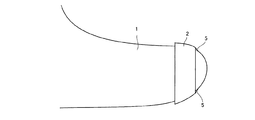
以下に本発明の実施例を添付図面を参照しつつ説明する。本発明に係る摩擦抵抗低減船は造波抵抗を低減するための球状船首1を備え、この球状船首1の外側に環状のプレート2を取り付け、このプレート2の内側面と球状船首1の外側面との間に間隔を設けている。
Embodiments of the present invention will be described below with reference to the accompanying drawings. The frictional resistance reduction ship according to the present invention includes a
尚、プレート2は環状とせずに、例えば球状船首1の下側半分を半周するような帯状としてもよい。また、プレート2と球状船首1とは必ずしも平行でなくてもよい。例えばプレート2と球状船首1の間隔は後方側において大きくなるようにしてもよい。
The
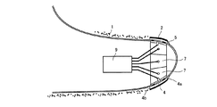
プレート2の内側面と球状船首1の外側面との間の間隔は隔壁部材3によって複数の流路4に区画されている。流路4の入口4aは船の航行方向を基準として前方となり出口4bは後方となる。入口4aには流路4内に異物が入り込むのを防止するプロテクター5を設けている。
A space between the inner surface of the
また、流路4の途中は流路断面積が小さくなった絞り部6とされている。船の航行に伴って入口4aから流入した水は流路4の絞り部6で絞られた後、急激に流路断面積が大きくなるため負圧が発生する。
In the middle of the flow path 4, the throttle section 6 has a reduced flow path cross-sectional area. The water that flows in from the
一方、プレート2に対応する船体内側にはミキシングチャンバー7を設けている。このミキシングチャンバー7は流路4ごとに設けてもまた複数の流路4に対し1つのミキシングチャンバー7を設けてもよい。
On the other hand, a
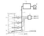
ミキシングチャンバー7は連通部8を介して流路4の絞り部6よりも下流側に連通している。ミキシングチャンバー7は配管を介してリザーバタンク9につながっており、このリザーバタンク9にはコンプレッサ10から加圧空気が供給される。ミキシングチャンバー7とリザーバタンク9をつなぐ配管は、主配管11とこれから分岐して各ミキシングチャンバー7に結合する分岐管11a、11b、11c、11dからなる。
The
各分岐管11a、11b、11c、11dには圧力調整または流量調整を行う調整バルブVa、Vb、Vc、Vdが設けられ、これら調整バルブVa、Vb、Vc、Vdのバルブの開度は制御装置12からの信号によって調整される。
Each
制御装置12には速度センサ及び喫水センサからの信号が送られ、これらセンサからの信号を処理し最適なバルブ開度を各調整バルブVa、Vb、Vc、Vdに出力する。
Signals from the speed sensor and the draft sensor are sent to the
即ち、仮にリザーバタンク9内が大気圧であったとすると、配管内の気液の界面は喫水面と等しくなる。この状態から、気液の界面がミキシングチャンバー7内まで下がっていないと、船舶の航行に伴って絞り部6の下流で負圧が発生しても、負圧の絶対値が不足し微細気泡を発生することができない。
In other words, if the
そこで、制御装置12からの信号は、速度センサからの信号によって微細気泡が発生する負圧を計算し、喫水センサからの信号によって配管内の気液の界面の位置を割り出し、各調整バルブの二次側圧がどれだけになれば気液の界面がミキシングチャンバー7内まで下がるかを計算し、それに応じた開度信号を各調整バルブに出力する。
Therefore, the signal from the
開度計算の一例を示せば、全開に対する開度をD(%)、速度をV(ノット)、喫水深さをH(m)とした場合、開度(D)=k×H/V(kは船の形状で決まる定数)で求めることができる。 An example of the opening calculation is as follows: Opening (D) = k × H / V (D) when opening to full open is D (%), speed is V (knots), and draft is H (m). k is a constant determined by the shape of the ship).
また、ミキシングチャンバー7にはCCDカメラなどの微細気泡発生の有無を検知する検知部材13を設けることが好ましい。制御装置12の計算は速度センサと喫水センサからの信号に基づいているが、配管内の状況や実際の取付角度などは考慮していないため、計算通りにはいかないことも考えられる。
そこで、検知部材13によって微細気泡が発生を発生していないことを検知した場合には、更に開度を大きくするフィードバック制御を行うことが好ましい。
The
Therefore, when the
また、信号の出力と微細気泡の発生との間にはタイムラグが生じる。一方船舶の特徴として、ピッチングやローリングは一定の間隔で上下動を繰り返す。そこで、船首が下降行程にあるときは更に喫水面からの距離が大きくなることを見越して開度を計算値よりも大きくし、逆に船首が上昇行程にあるときは更に喫水面からの距離が小さくなることを見越して開度を計算値よりも小さく設定するアクティブ制御を行うようにしてもよい。 Also, a time lag occurs between the signal output and the generation of fine bubbles. On the other hand, as a feature of the ship, pitching and rolling repeatedly move up and down at regular intervals. Therefore, when the bow is in the descending stroke, the opening is made larger than the calculated value in anticipation that the distance from the draft surface is further increased. Conversely, when the bow is in the ascending stroke, the distance from the draft surface is further increased. In anticipation of a decrease, active control may be performed in which the opening is set smaller than the calculated value.
以上において、船の航行に伴って流路4の入口4aから海水が流路4に取り入れられ、流路4内に取り入れられた海水は絞り部6で絞られ、この絞り部6の下流側において急激に解放されるため絞り部6の下流側で負圧が発生する。ここで、流路4は入口4a及び出口4b以外は連通部8を介してミキシングチャンバー7にのみ連通している。その結果、発生した負圧はミキシングチャンバー7に集中的に作用し、ミキシングチャンバー7内において効果的にケルビンーヘルムホルツ不安定現象が発生し、気泡が微細化され、出口4bから船体表面に沿って流れる。
As described above, seawater is taken into the flow path 4 from the
1…球状船首、2…プレート、3…隔壁部材、4…流路、4a…流路の入口、4b…流路の出口、5…プロテクター、6…絞り部、7…ミキシングチャンバー、8…連通部、9…リザーバタンク、10…コンプレッサ、11…主配管、11a、11b、11c、11d…分岐管、12…制御装置、13…検知部材、Va、Vb、Vc、Vd…調整バルブ。
DESCRIPTION OF
Claims (2)
Priority Applications (1)
| Application Number | Priority Date | Filing Date | Title |
|---|---|---|---|
| JP2011070615A JP2012201338A (en) | 2011-03-28 | 2011-03-28 | Frictional resistance reduced ship and method for operating the same |
Applications Claiming Priority (1)
| Application Number | Priority Date | Filing Date | Title |
|---|---|---|---|
| JP2011070615A JP2012201338A (en) | 2011-03-28 | 2011-03-28 | Frictional resistance reduced ship and method for operating the same |
Publications (1)
| Publication Number | Publication Date |
|---|---|
| JP2012201338A true JP2012201338A (en) | 2012-10-22 |
Family
ID=47182739
Family Applications (1)
| Application Number | Title | Priority Date | Filing Date |
|---|---|---|---|
| JP2011070615A Withdrawn JP2012201338A (en) | 2011-03-28 | 2011-03-28 | Frictional resistance reduced ship and method for operating the same |
Country Status (1)
| Country | Link |
|---|---|
| JP (1) | JP2012201338A (en) |
Cited By (5)
| Publication number | Priority date | Publication date | Assignee | Title |
|---|---|---|---|---|
| GB2515031A (en) * | 2013-06-11 | 2014-12-17 | Xocoatl Ltd | Watercraft hull |
| WO2016042746A1 (en) * | 2014-09-16 | 2016-03-24 | 雅 田篭 | Hull fluid resistance reduction device |
| JP2016064812A (en) * | 2014-09-16 | 2016-04-28 | 雅 田篭 | Hull fluid resistance reduction device |
| WO2022009477A1 (en) * | 2020-07-07 | 2022-01-13 | ジルスワイプピーティーワイ リミテッド | Method for operating friction resistance reduced ship |
| CN116424476A (en) * | 2023-06-13 | 2023-07-14 | 招商局金陵船舶(威海)有限公司 | Ship body bubble drag reduction device |
-
2011
- 2011-03-28 JP JP2011070615A patent/JP2012201338A/en not_active Withdrawn
Cited By (6)
| Publication number | Priority date | Publication date | Assignee | Title |
|---|---|---|---|---|
| GB2515031A (en) * | 2013-06-11 | 2014-12-17 | Xocoatl Ltd | Watercraft hull |
| WO2016042746A1 (en) * | 2014-09-16 | 2016-03-24 | 雅 田篭 | Hull fluid resistance reduction device |
| JP2016064812A (en) * | 2014-09-16 | 2016-04-28 | 雅 田篭 | Hull fluid resistance reduction device |
| WO2022009477A1 (en) * | 2020-07-07 | 2022-01-13 | ジルスワイプピーティーワイ リミテッド | Method for operating friction resistance reduced ship |
| CN116424476A (en) * | 2023-06-13 | 2023-07-14 | 招商局金陵船舶(威海)有限公司 | Ship body bubble drag reduction device |
| CN116424476B (en) * | 2023-06-13 | 2023-10-20 | 招商局金陵船舶(威海)有限公司 | Ship body bubble drag reduction device |
Similar Documents
| Publication | Publication Date | Title |
|---|---|---|
| JP4286313B1 (en) | Friction resistance reducing ship and its operating method | |
| JP2012201338A (en) | Frictional resistance reduced ship and method for operating the same | |
| JP4212640B1 (en) | Friction resistance reducing ship and its operating method | |
| JP4503688B1 (en) | Friction resistance reduction device for ships | |
| JP2008013128A (en) | Hull friction resistance reduction device | |
| KR101616261B1 (en) | Ship provided with bubble resistance reduction device, and method for reducing resistance of ship | |
| JP2012176637A (en) | Operating method of frictional resistance reduced ship | |
| WO2022009477A1 (en) | Method for operating friction resistance reduced ship | |
| JP5132828B1 (en) | Friction resistance reduction ship | |
| JP5791342B2 (en) | Friction resistance reduction type ship | |
| JP2010115942A (en) | Frictional resistance reduced vessel and its operation method | |
| JP2014184878A (en) | Ship equipped with bubble type resistance reduction device and resistance reduction method of ship | |
| JP2001106173A (en) | Frictional resistance reduced-ship | |
| KR102429041B1 (en) | Underwater vehicle and gas flow regulating apparatus for the underwater vehicle | |
| KR101599652B1 (en) | Resistance reduction device for ship | |
| JP2024516839A (en) | Systems and methods for reducing drag on vessels | |
| JP2010023765A (en) | Ship with reduced friction resistance and operating method therefor | |
| JP6664907B2 (en) | Air generator | |
| KR20140028409A (en) | Resistance reducing apparatus of ship, and ship having the same | |
| KR101487658B1 (en) | Resistance reducing apparatus of ship, and ship having the same | |
| JP2001106172A (en) | Frictional resistance reduced-ship | |
| CN101456446A (en) | Fluid negative pressure potential power machine | |
| JP2009274464A (en) | Frictional resistance-reduced ship, and method for operation thereof |
Legal Events
| Date | Code | Title | Description |
|---|---|---|---|
| A300 | Withdrawal of application because of no request for examination |
Free format text: JAPANESE INTERMEDIATE CODE: A300 Effective date: 20140603 |