JP2012201284A - Shock absorbing floor structure of electric vehicle - Google Patents
Shock absorbing floor structure of electric vehicle Download PDFInfo
- Publication number
- JP2012201284A JP2012201284A JP2011069174A JP2011069174A JP2012201284A JP 2012201284 A JP2012201284 A JP 2012201284A JP 2011069174 A JP2011069174 A JP 2011069174A JP 2011069174 A JP2011069174 A JP 2011069174A JP 2012201284 A JP2012201284 A JP 2012201284A
- Authority
- JP
- Japan
- Prior art keywords
- main frame
- longitudinal direction
- battery
- floor structure
- section
- Prior art date
- Legal status (The legal status is an assumption and is not a legal conclusion. Google has not performed a legal analysis and makes no representation as to the accuracy of the status listed.)
- Pending
Links
- 230000035939 shock Effects 0.000 title claims abstract description 24
- 229910000831 Steel Inorganic materials 0.000 claims abstract description 9
- 239000010959 steel Substances 0.000 claims abstract description 9
- 238000010521 absorption reaction Methods 0.000 claims description 3
- 238000003466 welding Methods 0.000 description 7
- XAGFODPZIPBFFR-UHFFFAOYSA-N aluminium Chemical compound [Al] XAGFODPZIPBFFR-UHFFFAOYSA-N 0.000 description 2
- 229910052782 aluminium Inorganic materials 0.000 description 2
- 238000005452 bending Methods 0.000 description 2
- 238000012423 maintenance Methods 0.000 description 2
- 239000000463 material Substances 0.000 description 2
- 238000000034 method Methods 0.000 description 2
- 210000001015 abdomen Anatomy 0.000 description 1
- 230000004308 accommodation Effects 0.000 description 1
- 230000009977 dual effect Effects 0.000 description 1
- 238000005516 engineering process Methods 0.000 description 1
- 238000001125 extrusion Methods 0.000 description 1
- 239000000446 fuel Substances 0.000 description 1
- 230000001771 impaired effect Effects 0.000 description 1
- 238000009434 installation Methods 0.000 description 1
- 239000002341 toxic gas Substances 0.000 description 1
Images
Landscapes
- Arrangement Or Mounting Of Propulsion Units For Vehicles (AREA)
- Body Structure For Vehicles (AREA)
Abstract
Description
本発明は、電気自動車の技術分野に関し、特に車体の衝撃吸収構造に関するものである。 The present invention relates to the technical field of electric vehicles, and more particularly to a shock absorbing structure for a vehicle body.
電気自動車は、その動力源として大量のバッテリー(蓄電池)を装備する必要があり、その収納場所はボンネット内、トランク内、床下など様々な工夫がなされてきた。しかしながら多くの電気自動車は、従来からのガソリンエンジンを駆動源とする車両に用いられていたシャシを前提にバッテリーの設置場所を確保しているので、室内空間が犠牲になったり、重量物たるバッテリーの搭載位置が高くなり車両の走行安定性を害したり、そもそも充分量のバッテリーの搭載が困難であるなど、様々な問題が存在していた。 An electric vehicle needs to be equipped with a large amount of battery (storage battery) as a power source, and various storage devices such as a bonnet, a trunk, and an underfloor have been provided. However, many electric vehicles have secured the installation location of the battery on the premise of a chassis used in a vehicle that uses a conventional gasoline engine as a driving source, so the indoor space is sacrificed or the heavy battery There are various problems, such as the mounting position of the vehicle becomes high and the running stability of the vehicle is impaired, and it is difficult to mount a sufficient amount of battery in the first place.
そのような中、特許文献1に示されているように、当初から電気自動車のシャシとして設計され上記問題を改善せんとする技術も存在する。特許文献1に記載の技術は、アルミ材を押出成型した中空部材を複数本組み合わせて車体のフロアを構成し、これら中空部材の中空部内にバッテリーを収納するのである。また、衝突時の衝撃を吸収するために、このアルミ押出材で構成されたフロアの先端に衝撃を吸収するためのバンパー構造が取り付けられている。
Under such circumstances, as shown in
しかしながら、上記の技術のように、別途フロアの先端にバンパー機構を設けるといった構造では不可避的にオーバーハングが長くなり、取り回しが悪くなる。また旋回時などに遠心力が働きやすくなり、運動性能を害する場合もある。更に、車両の全長を一定とすれば、バンパー機構の存在により、居住空間が狭くなるという問題もある。当然コスト高となる問題もある。 However, in the structure in which a bumper mechanism is separately provided at the tip of the floor as in the above technique, the overhang becomes unavoidably long, and the handling becomes worse. In addition, centrifugal force becomes easier to work during turning, which may impair movement performance. Furthermore, if the total length of the vehicle is constant, there is a problem that the living space becomes narrow due to the presence of the bumper mechanism. Of course, there is also a problem of high costs.
そこで本発明は、これらの問題点を解決するべくなされた発明であり、別途のバンパー機構を不要としつつ衝撃吸収能力に優れた車体の衝撃吸収構造を提供するものである。 Accordingly, the present invention has been made to solve these problems, and provides a shock absorbing structure for a vehicle body that has an excellent shock absorbing capability while eliminating the need for a separate bumper mechanism.
上記課題を解決するべく本願発明は、長手方向に直交する方向の断面がコ字断面を有し且つ下面に開口部が形成される長尺体であって、その長手方向が車体の前後方向となるように前輪の車軸中心位置以前から後輪の車軸中心位置以後にまで延在して配置した鋼板製の1本のメインフレーム内にバッテリーを収容可能とすると共に、前記メインフレームの幅を車幅全体の少なくとも25%以上とし、且つ、当該メインフレームを前輪よりも前方にまで延在させることにより該メインフレーム自体で正面衝突時の衝撃を吸収することを特徴とする。 In order to solve the above problems, the present invention is a long body in which a cross section in a direction perpendicular to the longitudinal direction has a U-shaped cross section and an opening is formed on the lower surface, and the longitudinal direction is the longitudinal direction of the vehicle body. In this way, the battery can be accommodated in one main frame made of steel plate that extends from before the axle center position of the front wheels to after the axle center position of the rear wheels. The main frame itself is at least 25% or more of the entire width, and the main frame extends forward from the front wheels, so that the main frame itself absorbs an impact during a frontal collision.
また、見方を変えると、長手方向に直交する方向の断面がコ字断面を有し且つ下面に開口部が形成される長尺体であって、その長手方向が車体の前後方向となるように前輪の車軸中心位置以前から後輪の車軸中心位置以後にまで延在して配置した鋼板製の1本のメインフレーム内にバッテリーを収容可能とすると共に、前記メインフレームは、車体の両側からそれぞれ車幅全体の40%分幅方向内側位置にまで架かるように幅広に構成されていることを特徴とする。 Further, from a different viewpoint, the cross section in the direction orthogonal to the longitudinal direction has a U-shaped cross section, and an opening is formed in the lower surface, and the longitudinal direction is the front-rear direction of the vehicle body. The battery can be accommodated in a single steel plate main frame that extends from the front wheel axle center position to the rear wheel axle center position, and the main frame is mounted on both sides of the vehicle body. It is configured to be wide so as to extend to an inner position in the width direction by 40% of the entire vehicle width.
要するに、メインフレームを前輪よりも更に前方にまで延在させると共に、延ばしたメインフレームの先端から一定の範囲にはバッテリーを収容しないことにより、メインフレーム自体の変形で衝撃を積極的に吸収せんとするものである。本発明ではメインフレームが「コの字断面」を有する鋼板製であるため、メインフレーム自体の強度が高く、効率的に衝撃を吸収することができる、また同時に、メインフレームの幅は車幅全体の25%以上となる大きさとされているので、大きな衝撃であってもメインフレームの変形により受け止めることができる。その結果、別途のバンパー機構を設ける必要が無く、更に大きな断面空間を有するメインフレームで効果的に衝撃を吸収できるので、短いオーバーハングを実現できる。即ち、取り回しに優れると共に広い居住空間を実現することができる。 In short, the main frame extends farther forward than the front wheels, and the battery is not housed within a certain area from the front end of the extended main frame. To do. In the present invention, since the main frame is made of a steel plate having a “U-shaped cross section”, the strength of the main frame itself is high and the shock can be absorbed efficiently. At the same time, the width of the main frame is the entire vehicle width. Therefore, even a large impact can be received by deformation of the main frame. As a result, it is not necessary to provide a separate bumper mechanism, and the impact can be effectively absorbed by the main frame having a larger sectional space, so that a short overhang can be realized. That is, it is excellent in handling and can realize a wide living space.
また、メインフレームは、車体の両側からそれぞれ車幅全体の40%分幅方向内側位置にまで架かるように幅広に構成されているので、オフセット衝突時においてもメインフレームで有効に衝撃を受け止めることが可能となる。 In addition, the main frame is so wide that it extends from both sides of the vehicle body to the inner side in the width direction by 40% of the entire vehicle width, so that the main frame can effectively receive an impact even during an offset collision. It becomes possible.
また、前記メインフレームは、断面視、コ字断面の下端から内側に突起したクランク部を有することを特徴とする。 The main frame has a crank portion protruding inward from the lower end of the U-shaped cross section when viewed in cross section.
このようにすれば、メインフレーム自体の剛性を上げることができると共に、衝撃吸収能力を向上させることができる。 In this way, it is possible to increase the rigidity of the main frame itself and to improve the shock absorbing ability.
また、前記開口部は、板状部材で閉塞されていることを特徴とする。 Further, the opening is closed by a plate member.
このようにすれば、メインフレームが所謂「ボックス構造」となるので、より剛性を確保でき、更に衝撃吸収能力も向上する。 In this way, since the main frame has a so-called “box structure”, more rigidity can be secured, and the shock absorbing ability can be further improved.
また、前記メインフレームの途中には、当該メインフレームの先端位置より高い位置にまで延在する補助フレームが固定され、当該補助フレームの先端にバンパービームが固定されることを特徴とする。 An auxiliary frame extending to a position higher than the tip position of the main frame is fixed in the middle of the main frame, and a bumper beam is fixed to the tip of the auxiliary frame.
このような構成を採用することで、衝突時の車両の安定性を確保することができる、即ち、本発明に係るフロア構造は、メインフレーム位置が低い位置に存在し且つその強度が非常に高いため、(メインフレームのみで衝撃を受け止めると)衝突時にともすると車両全体が前のめりになる可能性がある。そこでメインフレームよりも高い位置に補助フレームを延在させておくことによって、衝突時に車両全体が前のめりになる等の不安定さを取り除くことができる。更に、所望の高さ位置からの衝撃をメインフレームに伝達して吸収することが可能となると共に、衝撃を受ける高さ位置を国際規格等のバンパー衝突要件に合わせることが可能となる。 By adopting such a configuration, it is possible to ensure the stability of the vehicle at the time of collision, that is, the floor structure according to the present invention has a low main frame position and a very high strength. For this reason (if the impact is received only by the main frame), there is a possibility that the entire vehicle is turned forward in the event of a collision. Therefore, by extending the auxiliary frame to a position higher than the main frame, it is possible to remove instability such as the entire vehicle turning forward in the event of a collision. Furthermore, it is possible to transmit the shock from a desired height position to the main frame and absorb it, and to adjust the height position where the shock is received to bumper collision requirements such as international standards.
また、前記メインフレームの前端から所定分だけ奥まった位置にバッテリーを収容することを特徴とする。 In addition, the battery is housed in a position recessed by a predetermined amount from the front end of the main frame.
このようにすれば、万が一衝突等が発生した場合も変形するのはメインフレームの先端付近部分(即ちバッテリーが収容されていない部分)であるから、バッテリーの損傷を防止することができる。 In this way, even if a collision or the like occurs, it is the portion near the tip of the main frame (that is, the portion in which the battery is not housed) that is deformed, so that damage to the battery can be prevented.
本発明を適用することで、別途のバンパー機構を設ける必要が無く、更に大きな断面空間を有するメインフレームで効果的に衝撃を吸収できるので、短いオーバーハングを実現できる。即ち、取り回しに優れると共に広い居住空間を実現することができる。 By applying the present invention, it is not necessary to provide a separate bumper mechanism, and the impact can be effectively absorbed by the main frame having a larger sectional space, so that a short overhang can be realized. That is, it is excellent in handling and can realize a wide living space.
以下、添付図面を参照しつつ、本発明の実施形態の一例について説明を加える。なお、図面理解容易の為、各部の大きさや寸法を誇張して表現している部分があり、実際の製品と必ずしも一致しない部分があることを付記しておく。また各図面は符号の向きに見るものとし、当該向きを基本に上下左右、手前、奥と表現する。 Hereinafter, an example of an embodiment of the present invention will be described with reference to the accompanying drawings. For easy understanding of the drawings, it should be noted that there are portions where the size and dimensions of each portion are exaggerated and there are portions that do not necessarily match the actual product. In addition, each drawing is viewed in the direction of the reference sign, and is expressed as upper, lower, left, right, near, and back based on the direction.
〈衝撃吸収フロア構造の構成〉
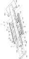
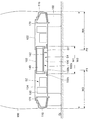
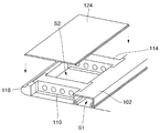
図1及び図2に示しているように、衝撃吸収フロア構造1は、下面に開口部102aが形成されるコ字断面(長手方向と直交する方向の断面)を有する長尺体であって、その長手方向が車体の前後方向となるように前輪の車軸中心位置L1以前から後輪の車軸中心位置L2以後にまで延在して配置された1本のメインフレーム102と、このメインフレーム102の側面から車体の幅方向両側にそれぞれ延在するように固定された3本ずつ(計6本)のサブフレーム104、106、108、110、112、114と、メインフレーム102と略平行に配置されサブフレーム104、108、112の先端同士を連結するサイドフレーム116、及び、サブフレーム106、110、114の先端同士を連結するサイドフレーム118と、開口部102a、並びに、メインフレーム102とサブフレーム104、106、108、110、112、114及びサイドフレーム116、118で囲まれた空間S2(以下単に「コンポーネント収容空間」という。)に対して下面側から蓋をする下部パネル部材120と、コンポーネント収容空間S2に対して上面側から蓋をする上部パネル部材122、124と、を備え、メインフレーム102、サブフレーム104、106、108、110、112、114、サイドフレーム116、118及び下部パネル部材120は溶接して固定されると共に、上部パネル部材122、124は着脱自在に取り付けられ、メインフレーム102内にバッテリー140を収容可能とすると共に、コンポーネント収容空間S2内に各種制御装置等のコンポーネント130を収容可能としている。なお、当該フロア構造1の上側にはアッパーボディー160が溶接固定される(図2参照)。
<Configuration of shock absorbing floor structure>
As shown in FIGS. 1 and 2, the shock absorbing
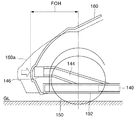
メインフレーム102は、1枚のスチール鋼板(本実施形態においては厚さ1.6mm)を折曲げ形成されている。折曲げた結果の形状は、断面視すると、所謂「コの字」の断面(上面と両側面に相当する)を有し、当該コ字断面の両方の下端部分からそれぞれ内側にクランク部102bが設けられている。またクランク部102bには外方向(幅方向外側)に向かってフランジ部102cが形成される(図2参照)。その結果、メインフレーム102下面が開口部102aとして開口している。またメインフレーム102の幅W1は、車両全体の幅W2に対して25%以上となるように構成されている。更にメインフレーム102は前輪150よりも前方(前輪150よりも正面側に突出した位置)にまで延在するように構成されている(図4参照)。
The
また見方を変えると、このメインフレーム102は、車体の両側からそれぞれ車幅全体W2の40%分幅方向内側位置P1、P2にまで架かるように幅広に構成されている。即ち、メインフレーム102は少なくともP1からP2の位置よりも幅広となるように構成されている。
In other words, the
このメインフレーム102は、車両の前輪軸中心位置L1よりも前から後輪軸中心位置L2よりも後まで伸びている。前輪軸中心位置L1よりも少し後方の位置には、当該メインフレーム102の側面から左右にサブフレーム104、106が溶接して取り付けられている。更にその後方に所定の間隔を空けてサブフレーム108、110が溶接して取り付けられている。更にその後方に所定の間隔を空けてサブフレーム112、114が溶接して取り付けられている。なお、これらのサブフレーム104〜114は全てメインフレーム102と略高さが揃う大きさに調整されている。
The
また、左右側それぞれのサブフレームの先端はサイドフレーム116、118が溶接固定されている。即ち、車両の進行方向に向かって左側に伸びているサブフレーム104、108、112の先端には、メインフレーム102と略平行に左側サイドフレーム116が溶接固定されている。同様に、車両の進行方向に向かって右側に伸びているサブフレーム106、110、114の先端にはメインフレーム102と略平行に右側サイドフレーム118が溶接固定されている。またこれらのサイドフレーム116、118はいずれもメインフレーム102と略高さが揃う大きさに調整されている。なお、これらメインフレーム102、サブフレーム104〜114及びサイドフレーム116、118で囲まれた空間(コンポーネント収納空間)S2に制御機器等のコンポーネント130が配置される。
Further, side frames 116 and 118 are fixed by welding at the front ends of the left and right subframes. That is, the
また、コンポーネント収納空間S2及びメインフレーム102下面の開口部102aを下側から蓋をするように下側パネル部材120が取り付けられている。この下部パネル部材120は一枚のフラットな形状とされており、メインフレーム102のフランジ部102c、各サブフレーム104〜114及びサイドフレームに溶接して固定されている。
A
メインフレーム102の後端付近には、左右方向にリヤサブフレーム126、128が固定されると共に、当該リヤサブフレーム126、128とメインフレームに跨がるようにリヤアンダーパネル132が設けられている。
Near the rear end of the
メインフレーム102の内部空間(メインフレーム102と下部パネル部材120で囲まれた空間)S1には、電気自動車の駆動源となるバッテリー140が必要量収容される。バッテリー140の出し入れはメインフレーム102の前端(若しくは後端)から行われる。バッテリー140はトレイ142上に載置されていて、更に当該トレイ142は両クランク部102bに跨がるように前後方向にスライド可能(例えばコロ構造などにより)に架設されている。その結果、バッテリー140は下部パネル部材120との間に一定の隙間G1を介して配置されることとなる。また、メインフレーム102内に収容されるバッテリー140は、メインフレーム102の前端及び後端から一定程度奥まった位置に配置固定される。即ち、全面若しくは後面衝突の際、設けられた空洞部分(バッテリーが収容されていない部分)のメインフレーム102自体が変形することによって効果的に衝突エネルギーを吸収することができるので、車両の衝突安全性向上を図ることができる。
A required amount of a
また、コンポーネント収納空間S2の上面には、2枚の上部パネル部材122、124がボルト170により締結固定されている。
In addition, two
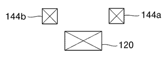
また、メインフレーム102の前輪車軸位置L1付近には、前方に向かって2本の補助フレーム144a、144bが備わっている。この補助フレーム144a、144bは、メインフレーム102から斜め前方に伸びると共に、先端付近は略水平となるように形成されている。更に、メインフレーム102からみて幅方向に広がるように形成されていて、フロア構造を正面視するとメインフレーム102の先端と、各補助フレーム114a、114bの先端は図5に示したような位置関係となる。更にこの補助フレーム144a、144bの先端にはバンパービーム146が取付けられている。なお本実施形態では、メインフレーム102の前端側にのみ補助フレーム144a、144bを設けているが、同様に後端側に設けるような構成を採用してもよい。
Further, two
〈衝撃吸収フロア構造の作用・機能〉
このように、メインフレーム102を前輪150よりも更に前方にまで延在させると共に、延ばしたメインフレーム150の先端から一定の範囲にはバッテリー140を収容しないことにより、メインフレーム102自体の変形で衝撃を積極的に吸収することができる。本発明ではメインフレーム102が「コの字断面」を有する鋼板製であるため、メインフレーム102自体の強度が高く、効率的に衝撃を吸収することができる、また同時に、メインフレーム102の幅W1は車全体の幅W2の25%以上となる大きさとされているので、大きな衝撃であってもメインフレーム102の変形により受け止めることができる。その結果、別途のバンパー機構を設ける必要が無く、更に大きな断面空間を有するメインフレーム102で効果的に衝撃を吸収できるので、短いオーバーハングを実現できる。即ち、取り回しに優れると共に広い居住空間を実現することができる。
<Operation and function of shock absorbing floor structure>
In this way, the
また、メインフレーム102は、車体の両側からそれぞれ車幅全体の40%分幅方向内側位置P1、P2にまで架かるように幅広に構成されているので、オフセット衝突時においてもメインフレーム102で有効に衝撃を受け止めることが可能となる。
In addition, the
また、メインフレーム102には、断面視、コ字断面の下端から内側に突起したクランク部102bを有しているので、メインフレーム102自体の剛性が高く、衝撃吸収能力に優れている。
Further, since the
また、メインフレーム102の開口部102は、下部パネル部材120で閉塞されているので、メインフレーム102が所謂「ボックス構造」となっており、より高い剛性の確保、衝撃吸収能力を備えている。
Further, since the
また、メインフレーム102には、当該メインフレーム102の先端位置より高い位置にまで延在する補助フレーム144a、144bが固定され、当該補助フレーム144a、144bの先端にバンパービーム146が固定されているので、衝突時の車両の安定性を確保することができる、即ち、本発明に係るフロア構造は、メインフレーム102の位置が低い位置に存在し且つその強度が非常に高いため、(メインフレーム102のみで衝撃を受け止めると)衝突時にともすると車両全体が前のめりになる可能性がある。そこでメインフレーム102よりも高い位置に補助フレーム144a、144bを延在させておくことによって、衝突時に車両全体が前のめりになる等の不安定さを取り除くことができる。更に、所望の高さ位置からの衝撃をメインフレーム102に伝達して吸収することが可能となると共に衝撃を受ける高さ位置を国際規格等のバンパー衝突要件に合わせることが可能となる。
Further, the
また、バッテリー140をメインフレーム102内に(前後方向に長く)纏めて配置することによって、側面衝突が発生した場合でも、バッテリー140を強固に保護することが可能となった。
In addition, by arranging the
また、大きな断面空間を有するメインフレーム102により正面や背面からの衝突時においても当該メインフレーム102自体がその衝撃を吸収できるので、バッテリー140の損傷を最小限に抑えることが可能となる。
In addition, the
また、メインフレーム102や各サブフレーム104〜114の長さを変えることでシャシの長さや幅の設計変更等に柔軟に対応することもできる。加えて、コンポーネント収容空間S2に各種制御機器等のコンポーネント130を設置することができるので別途室内やトランクスペースなどを犠牲にすることがない。
In addition, by changing the length of the
またバッテリー140と近い位置にこれらコンポーネント130を収容できるので短い配線で足りる。更にこのコンポーネント収容空間S2の上部に蓋をする上部パネル部材122、124はボルトにより取り外し可能とされているので、コンポーネント130のメンテナンスも容易である。
Moreover, since these
またメインフレーム102はスチール鋼板を折曲げて構成しているので、低コストかつ量産性に優れている。またフロア自体が下部パネル部材120と上部パネル部材122、124とを有する所謂「二重構造」に構成されていることからフロア構造自体の剛性が極めて高く、更に衝突時の衝撃を効果的にフロア全体に分散させることも可能となっている。
Further, since the
またバッテリー140は全てメインフレーム102内に収容されているので、何らかの理由でバッテリー140が大きく損傷等した場合でも室内側(フロア上方)への影響(有毒ガスや破片の飛散など)は極めて少なく乗員の安全性を確保することができる。
Moreover, since all the
また、メインフレーム102に備わるクランク部102bに架設されるトレイ142を備え、当該トレイ142上にバッテリー140が載置されている。これにより開口部102aから高さ方向に一定の隙間G1を有してバッテリー140が配置されることになるので、走行時等にフロア下を打撃するような事態(所謂「腹擦り」)が生じて下部パネル部材120が凹んだとしても、当該隙間G1の存在によりバッテリー140への直接の損傷を回避することができる。
In addition, a
またトレイ142がメインフレーム102の長手方向にスライド可能(例えばボールスライダなどのコロ構造を利用してスライド可能)とされているので、バッテリー140の出し入れが容易となり、メンテナンス作業等を行いやすい。
Further, since the
また、下部パネル部材120がフラットに形成されているため、特に高速走行時などフロア下の空気の乱れを抑えることができ、浮力の発生を未然に抑えることができると共に、空気抵抗の低減による燃費向上、風切り音の低減による静粛性向上を図ることができる。
In addition, since the
また、上部パネル部材122、124がフラットに形成されていて、メインフレーム102や各サブフレーム104〜114更にはサイドフレーム116、118と略面一となるように配置されているので、段差がなく乗降性に優れた床面を作り出すことができる。また床面がフラットなため座席等の室内設備を自由に配置することもできる。
Further, since the
1…フロア構造
102…メインフレーム
102a…開口部
102b…クランク部
102c…フランジ部
104、106、108、110、112、114…サブフレーム
116、118…サイドフレーム
120…下部パネル部材
122、124…上部パネル部材
126、128…リヤサイドフレーム
130…コンポーネント
132…リヤアンダーパネル
140…バッテリー
142…トレイ
144…補助フレーム
146…バンパービーム
150…タイヤ
160…アッパーボディー
L1…前輪車軸中心位置
L2…後輪車軸中心位置
S1…バッテリー収納スペース
S2…コンポーネント収納スペース
DESCRIPTION OF
Claims (6)
前記メインフレームの幅を車幅全体の少なくとも25%以上とし、且つ、当該メインフレームを前輪よりも前方にまで延在させることにより該メインフレーム自体で正面衝突時の衝撃を吸収する
ことを特徴とする電気自動車の衝撃吸収フロア構造。 A long body whose cross section perpendicular to the longitudinal direction has a U-shaped cross section and an opening is formed on the lower surface, from before the axle center position of the front wheels so that the longitudinal direction is the longitudinal direction of the vehicle body The battery can be accommodated in one main frame made of steel plate that extends to the rear wheel after the center position of the axle,
The width of the main frame is at least 25% or more of the entire vehicle width, and the main frame extends to the front of the front wheels so that the main frame itself absorbs a shock during a frontal collision. Electric vehicle shock absorption floor structure.
前記メインフレームは、車体の両側からそれぞれ車幅全体の40%分幅方向内側位置にまで架かるように幅広に構成されている
ことを特徴とする電気自動車の衝撃吸収フロア構造。 A long body whose cross section perpendicular to the longitudinal direction has a U-shaped cross section and an opening is formed on the lower surface, from before the axle center position of the front wheels so that the longitudinal direction is the longitudinal direction of the vehicle body The battery can be accommodated in one main frame made of steel plate that extends to the rear wheel after the center position of the axle,
The shock absorbing floor structure for an electric vehicle, wherein the main frame is configured to extend from both sides of the vehicle body to an inner position in the width direction by 40% of the entire vehicle width.
前記メインフレームは、断面視、コ字断面の下端から内側に突起したクランク部を有する
ことを特徴とする電気自動車の衝撃吸収フロア構造。 In claim 1 or 2,
The main frame has a crank portion that protrudes inward from a lower end of a U-shaped cross section in a cross-sectional view.
前記開口部は、板状部材で閉塞されている
ことを特徴とする電気自動車の衝撃吸収フロア構造。 In any one of Claims 1-3,
The opening is closed by a plate-like member. An electric vehicle shock absorbing floor structure, wherein:
前記メインフレームの途中には、当該メインフレームの先端位置より高い位置にまで延在する補助フレームが固定され、当該補助フレームの先端にバンパービームが固定される
ことを特徴とする電気自動車の衝撃吸収フロア構造。 In any one of Claims 1-4,
An auxiliary frame extending to a position higher than the tip position of the main frame is fixed in the middle of the main frame, and a bumper beam is fixed to the tip of the auxiliary frame. Floor structure.
前記メインフレームの前端から所定分だけ奥まった位置にバッテリーを収容する
ことを特徴とする電気自動車の衝撃吸収フロア構造。 In any one of Claims 1-5,
An impact-absorbing floor structure for an electric vehicle, wherein a battery is accommodated at a position recessed by a predetermined amount from the front end of the main frame.
Priority Applications (1)
| Application Number | Priority Date | Filing Date | Title |
|---|---|---|---|
| JP2011069174A JP2012201284A (en) | 2011-03-28 | 2011-03-28 | Shock absorbing floor structure of electric vehicle |
Applications Claiming Priority (1)
| Application Number | Priority Date | Filing Date | Title |
|---|---|---|---|
| JP2011069174A JP2012201284A (en) | 2011-03-28 | 2011-03-28 | Shock absorbing floor structure of electric vehicle |
Publications (1)
| Publication Number | Publication Date |
|---|---|
| JP2012201284A true JP2012201284A (en) | 2012-10-22 |
Family
ID=47182695
Family Applications (1)
| Application Number | Title | Priority Date | Filing Date |
|---|---|---|---|
| JP2011069174A Pending JP2012201284A (en) | 2011-03-28 | 2011-03-28 | Shock absorbing floor structure of electric vehicle |
Country Status (1)
| Country | Link |
|---|---|
| JP (1) | JP2012201284A (en) |
Cited By (5)
| Publication number | Priority date | Publication date | Assignee | Title |
|---|---|---|---|---|
| JPWO2014128869A1 (en) * | 2013-02-20 | 2017-02-02 | トヨタ自動車株式会社 | Body structure |
| DE102018105371A1 (en) | 2017-03-23 | 2018-09-27 | Toyota Jidosha Kabushiki Kaisha | VEHICLE SUPPORT STRUCTURE |
| CN109204574A (en) * | 2018-10-16 | 2019-01-15 | 广州汽车集团股份有限公司 | A kind of new-energy automobile body structure |
| US12233938B2 (en) | 2023-02-21 | 2025-02-25 | Subaru Corporation | Front frame structure for electric vehicle |
| US12263886B2 (en) | 2023-02-21 | 2025-04-01 | Subaru Corporation | Front frame structure for electric vehicle |
Citations (1)
| Publication number | Priority date | Publication date | Assignee | Title |
|---|---|---|---|---|
| JP2007326474A (en) * | 2006-06-08 | 2007-12-20 | Toyota Motor Corp | Electric vehicle powered by fuel cell |
-
2011
- 2011-03-28 JP JP2011069174A patent/JP2012201284A/en active Pending
Patent Citations (1)
| Publication number | Priority date | Publication date | Assignee | Title |
|---|---|---|---|---|
| JP2007326474A (en) * | 2006-06-08 | 2007-12-20 | Toyota Motor Corp | Electric vehicle powered by fuel cell |
Cited By (7)
| Publication number | Priority date | Publication date | Assignee | Title |
|---|---|---|---|---|
| JPWO2014128869A1 (en) * | 2013-02-20 | 2017-02-02 | トヨタ自動車株式会社 | Body structure |
| DE102018105371A1 (en) | 2017-03-23 | 2018-09-27 | Toyota Jidosha Kabushiki Kaisha | VEHICLE SUPPORT STRUCTURE |
| US10632827B2 (en) | 2017-03-23 | 2020-04-28 | Toyota Jidosha Kabushiki Kaisha | Vehicle lower portion structure |
| DE102018105371B4 (en) | 2017-03-23 | 2025-04-10 | Toyota Jidosha Kabushiki Kaisha | VEHICLE SUBSTRUCTURE |
| CN109204574A (en) * | 2018-10-16 | 2019-01-15 | 广州汽车集团股份有限公司 | A kind of new-energy automobile body structure |
| US12233938B2 (en) | 2023-02-21 | 2025-02-25 | Subaru Corporation | Front frame structure for electric vehicle |
| US12263886B2 (en) | 2023-02-21 | 2025-04-01 | Subaru Corporation | Front frame structure for electric vehicle |
Similar Documents
| Publication | Publication Date | Title |
|---|---|---|
| JP5698581B2 (en) | Electric vehicle body floor structure | |
| JP4853197B2 (en) | Vehicle front structure | |
| US8764104B2 (en) | Structure of front section of vehicle body | |
| JP5953887B2 (en) | Vehicle front structure | |
| CN109421805B (en) | Vehicle body structure of electric vehicle | |
| JPWO2018163815A1 (en) | Lower body structure of vehicle | |
| JP7422518B2 (en) | Support device for vehicle battery pack and electric vehicle | |
| KR101500366B1 (en) | Structure for absorbing collision energy of front of vehicle | |
| CN112572123A (en) | Vehicle lower structure | |
| CN103231739B (en) | For vehicle vehicle frame and there is its vehicle | |
| WO2012035987A1 (en) | Battery pack vehicle installation structure | |
| US9669785B2 (en) | Bumper assemblies including spacer members and vehicles incorporating the same | |
| JP2013028192A (en) | Battery cooling structure for motor vehicle | |
| EP2505458B1 (en) | Compact vehicle frame structure | |
| JP2012201284A (en) | Shock absorbing floor structure of electric vehicle | |
| JP2018177158A (en) | Fuel cell vehicle | |
| JP2022063125A (en) | Support device of battery pack and electric truck | |
| JP2011195057A (en) | Front body structure of electric vehicle | |
| JP5488506B2 (en) | Lower body structure of the vehicle | |
| US8042834B2 (en) | Front structure of vehicle | |
| JP2013018429A (en) | Rear part structure of vehicle | |
| JP2016002795A (en) | Vehicle battery protection structure | |
| JP2016104625A (en) | Vehicle body front structure for vehicle | |
| JP2016055870A (en) | Vehicle-body front structure of vehicle | |
| KR20130070358A (en) | Bumper beam unit for vehicle |
Legal Events
| Date | Code | Title | Description |
|---|---|---|---|
| A711 | Notification of change in applicant |
Free format text: JAPANESE INTERMEDIATE CODE: A711 Effective date: 20140218 |
|
| A621 | Written request for application examination |
Free format text: JAPANESE INTERMEDIATE CODE: A621 Effective date: 20140224 |
|
| A131 | Notification of reasons for refusal |
Free format text: JAPANESE INTERMEDIATE CODE: A131 Effective date: 20150114 |
|
| A977 | Report on retrieval |
Free format text: JAPANESE INTERMEDIATE CODE: A971007 Effective date: 20150115 |
|
| A02 | Decision of refusal |
Free format text: JAPANESE INTERMEDIATE CODE: A02 Effective date: 20150629 |