JP2012199302A - Substrate container - Google Patents
Substrate container Download PDFInfo
- Publication number
- JP2012199302A JP2012199302A JP2011061155A JP2011061155A JP2012199302A JP 2012199302 A JP2012199302 A JP 2012199302A JP 2011061155 A JP2011061155 A JP 2011061155A JP 2011061155 A JP2011061155 A JP 2011061155A JP 2012199302 A JP2012199302 A JP 2012199302A
- Authority
- JP
- Japan
- Prior art keywords
- substrate
- plate
- internal space
- partition plate
- foup
- Prior art date
- Legal status (The legal status is an assumption and is not a legal conclusion. Google has not performed a legal analysis and makes no representation as to the accuracy of the status listed.)
- Granted
Links
Images


Landscapes
- Packaging Frangible Articles (AREA)
- Container, Conveyance, Adherence, Positioning, Of Wafer (AREA)
Abstract
Description
本発明は、半導体ウエハ、液晶ディスプレイ用基板、プラズマディスプレイ用基板、有機EL用基板、FED(Field Emission Display)用基板、光ディスプレイ用基板、磁気ディスク用基板、光磁気ディスク用基板、フォトマスク用基板、太陽電池用基板(以下、単に基板と称する)を複数枚収容する基板収容器に関する。 The present invention relates to a semiconductor wafer, a liquid crystal display substrate, a plasma display substrate, an organic EL substrate, an FED (Field Emission Display) substrate, an optical display substrate, a magnetic disk substrate, a magneto-optical disk substrate, and a photomask substrate. The present invention relates to a substrate container that accommodates a plurality of substrates and solar cell substrates (hereinafter simply referred to as substrates).
従来、この種の装置として、密閉した雰囲気に複数枚の基板を収容して搬送するための基板収容器が挙げられる。この基板収容器は、FOUP(Front Opening Unified Pod)と呼ばれている。このFOUPは、FOUP本体と、開口部と、支持溝と、蓋とを備えている。FOUP本体は、一側面に開口部を備え、内部空間に多段の支持溝が形成されている。複数枚の基板が開口部から多段の支持溝に載置されて収納されると、蓋が開口部に取り付けられる。そして、複数枚の基板は、FOUPごと所望の場所へ搬送される(例えば、特許文献1参照)。 Conventionally, as this type of apparatus, there is a substrate container for accommodating and transporting a plurality of substrates in a sealed atmosphere. This substrate container is called FOUP (Front Opening Unified Pod). The FOUP includes a FOUP main body, an opening, a support groove, and a lid. The FOUP main body has an opening on one side surface, and multistage support grooves are formed in the internal space. When a plurality of substrates are placed and stored in the multistage support groove from the opening, the lid is attached to the opening. Then, the plurality of substrates are transported to a desired place together with the FOUP (see, for example, Patent Document 1).
このような構成のFOUPを用いると、FOUP内の僅かな内部空間の清浄度を高めることにより、工場全体を高清浄度のクリーンルーム化した場合と同様の効果を得ることができる。したがって、クリーンルーム全体を高清浄度化するのに要する設備投資やその維持費を削減して、効率的に生産を行うことができる。また、FOUPの蓋を開放した状態で、窒素ガスを各基板に吹き付けて、各基板に付着している汚染物質を除去することも行われる。 When the FOUP having such a configuration is used, the same effect as when the entire factory is made a clean room with a high cleanliness can be obtained by increasing the cleanliness of a small internal space in the FOUP. Therefore, it is possible to reduce the capital investment required for increasing the cleanliness of the entire clean room and its maintenance cost, and to perform production efficiently. In addition, with the FOUP lid open, nitrogen gas is blown onto each substrate to remove contaminants adhering to each substrate.
ところで、多くの基板を同時に収容して搬送できるように、一般的にFOUPは、例えば、25枚の基板を水平姿勢で積層して収容できるように構成されている。しかし、最近では、半導体デバイスの多様化に起因して、多品種少量生産の要望も増えている。そのような場合には、異なるデバイス用の基板が同一のFOUP内に混在されて搬送されることもある。また、25枚の内部空間のうち、半分程度(例えば、12枚の基板)だけを使うこともある。 By the way, so that many substrates can be accommodated and transported at the same time, the FOUP is generally configured to accommodate, for example, 25 substrates stacked in a horizontal position. However, recently, due to the diversification of semiconductor devices, demand for high-mix low-volume production is increasing. In such a case, substrates for different devices may be mixed and transported in the same FOUP. Further, only about half of the 25 internal spaces (for example, 12 substrates) may be used.
しかしながら、このような構成を有する従来例の場合には、次のような問題がある。
すなわち、従来のFOUPは、異なる種類の基板が混在すると、FOUP内において異種の基板の間で汚染が生じる相互汚染の恐れがある。例えば、銅を用いている基板から銅被膜の破片等が、アルミニウム配線の基板に付着すると、銅が基板上のデバイスに致命的な欠陥を与える恐れがある。
However, the conventional example having such a configuration has the following problems.
That is, in the conventional FOUP, when different types of substrates are mixed, there is a risk of mutual contamination in which contamination occurs between different types of substrates in the FOUP. For example, when a piece of a copper film adheres to a substrate of an aluminum wiring from a substrate using copper, there is a risk that the copper gives a fatal defect to a device on the substrate.
また、FOUPの内部空間の半分程度を同種の基板で使用する場合、基板が処理前に汚染されていると、たとえ処理によって基板を清浄化したとしても、FOUPの内部空間が汚染されているので、基板をFOUPに戻した際に、FOUPを介しての基板の相互汚染が生じる恐れがある。したがって、従来のFOUPでは、たとえ窒素ガスを吹き付けるようにして、処理前の基板から汚染物を除去するようにしても基板の相互汚染を避けられない恐れがある。 Also, when about half of the internal space of the FOUP is used with the same type of substrate, if the substrate is contaminated before processing, the internal space of the FOUP is contaminated even if the substrate is cleaned by processing. When the substrate is returned to the FOUP, cross contamination of the substrate through the FOUP may occur. Therefore, in the conventional FOUP, even if nitrogen gas is blown to remove contaminants from the substrate before processing, there is a risk that cross contamination of the substrates cannot be avoided.
なお、上記のような問題を回避するために、例えば、異種の基板や異なる金属材料を用いた基板を別々のFOUPで搬送することが考えられる。しかし、このような手法によると、FOUPの個数が増大するのでコストアップにつながり、さらにFOUPの保管スペースも増大する別異の問題が生じる。また、基板をFOUPから取り出して処理している間に、FOUPを洗浄することも考えられる。しかし、FOUPの洗浄時間が基板の処理時間より長くなる場合には、処理済の基板にFOUP待ちの時間が生じるので、スループットが低下するという別異の問題が生じることになる。したがって、上記の問題を解決することにはならない。 In order to avoid the above problems, for example, it is conceivable to transport different substrates or substrates using different metal materials by separate FOUPs. However, according to such a method, the number of FOUPs increases, leading to an increase in cost, and another problem of increasing the storage space for FOUPs arises. It is also conceivable to clean the FOUP while the substrate is being removed from the FOUP and processed. However, if the FOUP cleaning time is longer than the substrate processing time, a FOUP waiting time is generated on the processed substrate, which causes another problem that the throughput is lowered. Therefore, the above problem is not solved.
本発明は、このような事情に鑑みてなされたものであって、内部空間の雰囲気を仕切ることによって、基板の相互汚染が生じるのを抑制することができる基板収容器を提供することを目的とする。 This invention is made in view of such a situation, Comprising: It aims at providing the board | substrate container which can suppress that the mutual contamination of a board | substrate arises by partitioning the atmosphere of internal space. To do.
本発明は、このような目的を達成するために、次のような構成をとる。
すなわち、請求項1に記載の発明は、複数枚の基板を収容する基板収容器において、内部空間を有する収容器本体と、前記収容器本体に形成され、前記内部空間に連通した開口部と、前記収容器本体の内壁に設けられ、基板の端縁下面を当接支持する複数の支持溝と、前記開口部に着脱自在の蓋と、前記複数の支持溝に着脱自在に装着されて、前記内部空間を複数の雰囲気に仕切る仕切り板と、を備えていることを特徴とするものである。
In order to achieve such an object, the present invention has the following configuration.
That is, the invention according to claim 1 is a substrate container that accommodates a plurality of substrates, a container body having an internal space, an opening formed in the container body and communicating with the internal space, A plurality of support grooves provided on the inner wall of the container main body, for abutting and supporting the lower surface of the edge of the substrate; a lid detachably attached to the opening; and And a partition plate that partitions the internal space into a plurality of atmospheres.
[作用・効果]請求項1に記載の発明によれば、仕切り板を支持溝に装着すると、収容器本体の内部空間を複数の雰囲気に仕切ることができる。したがって、内部空間を、異なる雰囲気ごとに使い分けることにより、収容器本体における基板の相互汚染を抑制することができる。 [Operation / Effect] According to the first aspect of the present invention, when the partition plate is attached to the support groove, the internal space of the container body can be partitioned into a plurality of atmospheres. Therefore, the cross-contamination of the board | substrate in a container main body can be suppressed by using an internal space for every different atmosphere.
また、仕切り板は支持溝に着脱自在であり、特殊な基板収容器でなく、規格化された標準的な基板収容器を用いることができるので、既存の装置に容易に適用できるとともに、コストの上昇を仕切り板に相当する分だけですませることができる。したがって、内部空間の雰囲気を容易に低コストで分離することができる。 In addition, the partition plate can be attached to and detached from the support groove, and a standardized standard substrate container can be used instead of a special substrate container. The rise can be done only by the amount corresponding to the partition plate. Therefore, the atmosphere of the internal space can be easily separated at a low cost.
なお、ここでいう「雰囲気を仕切る」とは、部材で空間を完全に分離するのではなく、空間の相互間で気体が容易に行き来するのを抑制する程度に空間を分けることをいう。 Here, “partitioning the atmosphere” refers to dividing the space to such an extent that the gas is not easily separated between the spaces, but is not completely separated by the members.
また、本発明において、前記仕切り板は、ダミー基板であることが好ましい(請求項2)。仕切り板を特殊な材料で構成することなく、処理する基板と同種のダミー基板とするので、仕切り板からの汚染を容易に低コストで抑制することができる。 In the present invention, it is preferable that the partition plate is a dummy substrate. Since the partition plate is made of a dummy substrate of the same type as the substrate to be processed without being made of a special material, contamination from the partition plate can be easily suppressed at low cost.
また、本発明において、前記仕切り板は、基板とは異なる板状部材で構成されていることが好ましい(請求項3)。基板とは異なる板状部材で仕切り板を構成するので、仕切り板を基板収容器の内部空間に応じた形状にすることができる。したがって、仕切り板の形状を変えることにより、内部空間の気流を適切に抑制できるので、基板相互間の汚染をさらに抑制することができる。 Moreover, in this invention, it is preferable that the said partition plate is comprised with the plate-shaped member different from a board | substrate (Claim 3). Since the partition plate is composed of a plate-like member different from the substrate, the partition plate can be shaped according to the internal space of the substrate container. Therefore, by changing the shape of the partition plate, the airflow in the internal space can be appropriately suppressed, so that contamination between the substrates can be further suppressed.
また、本発明において、前記仕切り板は、基板とは異なる板状部材で構成され、前記板状部材は、内部空間の内壁に当接する端面と、内部空間の内壁から離間した端面とを備えていることが好ましい(請求項4)。基板とは異なる板状部材で仕切り板を構成し、板状部材は、端面が内部空間の内壁に当接する部分と、端面が内部空間の内壁から離間する部分とを有する。したがって、板状部材の形状に応じて、雰囲気を仕切る度合いを所望の度合いにすることができる。 Further, in the present invention, the partition plate is formed of a plate-like member different from the substrate, and the plate-like member includes an end face that abuts on the inner wall of the internal space and an end face that is separated from the inner wall of the internal space. (Claim 4). The partition plate is configured by a plate-like member different from the substrate, and the plate-like member has a portion where the end surface abuts against the inner wall of the internal space and a portion where the end surface is separated from the inner wall of the internal space. Therefore, the degree of partitioning the atmosphere can be set to a desired degree according to the shape of the plate-like member.
なお、ここでいう「内部空間の内壁」とは、基板収容器の内側で内部空間を形成する面であり、内部空間の内壁に設けられた部材を含む。 Here, the “inner wall of the internal space” is a surface that forms the internal space inside the substrate container, and includes members provided on the inner wall of the internal space.
また、本発明において、前記仕切り板は、基板とは異なる板状部材で構成され、前記板状部材は、周囲が内部空間の内壁に当接する端面を備えていることが好ましい(請求項5)。周囲が内部空間の内壁に当接する端面を備えた板状部材で仕切り板を構成するので、雰囲気の分離度合いを高くすることができる。したがって、基板の相互汚染の抑制度合いを高くすることができる。 In the present invention, it is preferable that the partition plate is composed of a plate-like member different from the substrate, and the plate-like member has an end surface whose periphery abuts against the inner wall of the internal space. . Since the partition plate is composed of a plate-like member having an end surface that contacts the inner wall of the internal space, the degree of separation of the atmosphere can be increased. Therefore, the degree of suppression of mutual contamination of the substrate can be increased.
なお、ここでいう「内部空間の内壁」とは、基板収容器の内側で内部空間を形成する面であり、内部空間の内壁に設けられた部材を含む。 Here, the “inner wall of the internal space” is a surface that forms the internal space inside the substrate container, and includes members provided on the inner wall of the internal space.
また、本発明において、前記板状部材は、縦断面形状が起伏状に構成されていることが好ましい(請求項6)。板状部材の縦断面形状を起伏状にするので、仕切り板の上方に載置された基板からパーティクルが落下したとしても、山谷部分でパーティクルが移動しづらくできる。したがって、落下したパーティクルが搬送中に仕切り板を移動して、他の基板を汚染するような相互汚染を抑制することができる。 Moreover, in this invention, it is preferable that the said plate-shaped member is comprised in the undulating shape in the longitudinal cross-section (Claim 6). Since the vertical cross-sectional shape of the plate-shaped member is undulated, even if the particles fall from the substrate placed above the partition plate, the particles can hardly move in the mountain and valley portions. Therefore, it is possible to suppress cross-contamination such that the dropped particles move the partition plate during transportation and contaminate other substrates.
また、本発明において、前記板状部材は、平面視で中心部に一つの貫通穴が形成されていることが好ましい(請求項7)。平面視で中心部に一つの貫通穴を形成してあるので、板状部材の軽量化を図ることができる。貫通穴は、板状部材の中心部にだけ形成されているので、基板の端面と支持溝との摺動によってパーティクルが発生しても、貫通穴を通してパーティクルが落下することによる相互汚染は抑制できる。また、不活性ガスなどを注入する際に、仕切られた複数の雰囲気にも不活性ガスを送り込むことができる。さらに、貫通穴の大きさを変えることにより、不活性ガスの気流を調整することができる。 Moreover, in this invention, it is preferable that the said plate-shaped member has one through-hole formed in center part by planar view (Claim 7). Since one through hole is formed in the central portion in plan view, the weight of the plate-like member can be reduced. Since the through-hole is formed only at the center of the plate-like member, even if particles are generated by sliding between the end face of the substrate and the support groove, cross-contamination due to particles falling through the through-hole can be suppressed. . In addition, when an inert gas or the like is injected, the inert gas can be fed into a plurality of partitioned atmospheres. Furthermore, the flow of the inert gas can be adjusted by changing the size of the through hole.
また、本発明において、前記板状部材は、平面視で中心領域に複数個の小さな貫通孔が形成されていることが好ましい(請求項8)。複数個の小さな貫通孔により板状部材の軽量化を図ることができる。貫通孔は、平面視で板状部材の中心領域にのみ形成されているので、基板の端面と支持溝との摺動によってパーティクルが発生しても、貫通孔からパーティクルが落下することによる相互汚染を抑制できる。また、不活性ガスなどを注入する際に、仕切られた複数の雰囲気にも不活性ガスを送り込むことができる。さらに、貫通孔の大きさや数を変えることにより、不活性ガスの気流を調整することができる。 In the present invention, it is preferable that the plate-like member has a plurality of small through holes formed in a central region in plan view. The plate-like member can be reduced in weight by a plurality of small through holes. Since the through-hole is formed only in the central region of the plate-like member in plan view, even if particles are generated by sliding between the end face of the substrate and the support groove, cross-contamination due to particles falling from the through-hole Can be suppressed. In addition, when an inert gas or the like is injected, the inert gas can be fed into a plurality of partitioned atmospheres. Furthermore, the flow of the inert gas can be adjusted by changing the size and number of the through holes.
また、本発明において、前記仕切り板は、複数枚の板状部材と、前記複数の支持溝の間隔で前記各板状部材を支持する支持部材とを備え、前記複数枚の板状部材は、複数個の小さな貫通孔が形成されており、前記複数個の小さな貫通孔は、平面視で、前記板状部材ごとに異なる領域に形成されていることが好ましい(請求項9)。複数枚の板状部材を支持部材で離間させて仕切り板が構成されているので、雰囲気の分離度合いを高くすることができる。さらに、複数枚の板状部材は複数個の貫通孔が形成されているので、板状部材が複数であっても重量の増加を抑制することができる。その上、各板状部材の貫通孔は、平面視で板状部材ごとに異なる領域に形成されているので、パーティクル等が上から下に落下しづらくできる。したがって、貫通孔を介しての基板の相互汚染を抑制できる。また、不活性ガスなどを注入する際に、仕切られた複数の雰囲気にも不活性ガスを送り込むことができる。さらに、貫通孔の大きさや数を変えることにより、不活性ガスの気流を調整することができる。 Further, in the present invention, the partition plate includes a plurality of plate-like members and a support member that supports the plate-like members at intervals of the plurality of support grooves, and the plurality of plate-like members include: A plurality of small through-holes are formed, and the plurality of small through-holes are preferably formed in different regions for each of the plate-like members in plan view. Since the partition plate is configured by separating the plurality of plate-like members with the support member, the degree of separation of the atmosphere can be increased. Furthermore, since a plurality of plate-like members are formed with a plurality of through holes, an increase in weight can be suppressed even if there are a plurality of plate-like members. In addition, since the through holes of each plate-like member are formed in different regions for each plate-like member in plan view, particles or the like can hardly fall from the top to the bottom. Therefore, mutual contamination of the substrate through the through hole can be suppressed. In addition, when an inert gas or the like is injected, the inert gas can be fed into a plurality of partitioned atmospheres. Furthermore, the flow of the inert gas can be adjusted by changing the size and number of the through holes.
また、本発明において、前記収容器本体は、前記内部空間の圧力と外部圧力とを一定に保つ機能を備えた吸入部と排気部とを備え、前記吸入部から不活性ガスを圧入されるとともに、前記排気部から前記内部空間内の気体が強制的に排気されることが好ましい(請求項10)。吸入部から内部空間に不活性ガスを圧入し、排気部から内部空間の気体を強制的に排気することにより、内部空間を不活性ガスで満たすことができる。その際、仕切り板で内部空間を仕切っているので、不活性ガスの使用量を低減することができる。 Further, in the present invention, the container body includes a suction part and an exhaust part having a function of keeping the pressure in the internal space and the external pressure constant, and an inert gas is press-fitted from the suction part. It is preferable that the gas in the internal space is forcibly exhausted from the exhaust part. By injecting an inert gas into the internal space from the suction portion and forcibly exhausting the gas in the internal space from the exhaust portion, the internal space can be filled with the inert gas. At that time, since the internal space is partitioned by the partition plate, the amount of inert gas used can be reduced.
本発明に係る基板収容器によれば、仕切り板を装着すると、収容器本体の内部空間を複数の雰囲気に仕切ることができる。したがって、内部空間を、異なる雰囲気ごとに使い分けることにより、収容器本体における基板の相互汚染を抑制することができる。 According to the substrate container of the present invention, when the partition plate is attached, the internal space of the container body can be partitioned into a plurality of atmospheres. Therefore, the cross-contamination of the board | substrate in a container main body can be suppressed by using an internal space for every different atmosphere.
また、仕切り板は支持溝に着脱自在であり、規格化された標準的な基板収容器を用いることができるので、既存の装置に容易に適用できるとともに、コストの上昇は、仕切り板だけですむ。したがって、内部空間の雰囲気を容易に低コストで分離することができる。 In addition, since the partition plate can be freely attached to and detached from the support groove and a standardized standard substrate container can be used, it can be easily applied to existing equipment, and the cost can be increased only by the partition plate. . Therefore, the atmosphere of the internal space can be easily separated at a low cost.
本発明に係る基板収容器としてFOUP(Front Opening Unified Pod)を例にとって以下に説明する。 As an example of the substrate container according to the present invention, a front opening unified pod (FOUP) will be described below.
以下、図面を参照して本発明の実施例1を説明する。
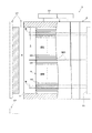
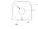
図1は、実施例1に係るFOUPの概略構成を示す縦断面図であり、図2は、実施例1に係る仕切り板を示す平面図であり、図3は、実施例1に係る仕切り板を示す正面図である。
Embodiment 1 of the present invention will be described below with reference to the drawings.
1 is a longitudinal sectional view showing a schematic configuration of a FOUP according to the first embodiment, FIG. 2 is a plan view showing a partition plate according to the first embodiment, and FIG. 3 is a partition plate according to the first embodiment. FIG.
本発明における「基板収容器」に相当するFOUP1は、複数枚の基板Wを水平姿勢で積層して収納可能に構成されている。FOUP1は、収容器本体3を備えている。この収容器本体3は、内部空間5を備え、内部空間5の正面側には開口部7を備えている。収容器本体3は、例えば、ポリカーボネートなどで成形加工によって製造されている。内部空間5のうち、開口部7の両側面には、基板Wを載置するための支持部9が設けられている。また、内部空間5の奥側には、当接部11が設けられている。
The FOUP 1 corresponding to the “substrate container” in the present invention is configured to be capable of storing a plurality of substrates W stacked in a horizontal posture. The FOUP 1 includes a
支持部9は、例えば、25枚の基板Wを載置できるように、25個の支持溝13を備えている。支持溝13は、上向き面にて基板Wの下面を当接して基板Wを水平姿勢に支持する。支持部9の奥側に位置する当接部11は、基板Wの後側端面が当接し、基板Wの水平位置を固定する。
The
FOUP1の上面には、搬送機構(図示省略)が把持するための把持部15を備えている。なお、図3では、図示の関係上、把持部15を省略している。
On the upper surface of the FOUP 1, a
開口部7は、蓋17が着脱可能に構成されている。この蓋17は、ロードポート(図示省略)にFOUP1が載置された状態で、ロードポートが備える開閉機構(図示省略)によって開口部7に装着されたり、取り外されたりする。蓋17が開口部7に装着されると、FOUP1の内部空間5が外部の雰囲気と遮断される。
The
支持部9のうち、例えば、高さ方向の中央部付近にある一つの支持溝13には、仕切り板DP1が載置されている。この仕切り板DP1は、基板Wと同種の基板であってデバイスが形成されていないダミー基板である。例えば、図3のように支持部9の高さ方向における中央部(上から13段目、下から13段目)に仕切り板DP1を載置する。
Of the
このように仕切り板DP1を載置すると、仕切り板DP1によって上部の第1の空間SP1の雰囲気と、下部の第2の空間SP2の雰囲気とを分離することができる。仕切り板DP1は、内部空間5を二つの空間SP1,SP2に分離するが、分離したい空間の大きさに応じて支持部9の任意の位置に載置することができる。
When the partition plate DP1 is placed in this way, the atmosphere of the upper first space SP1 and the atmosphere of the lower second space SP2 can be separated by the partition plate DP1. The partition plate DP1 separates the
なお、分離された二つの空間SP1,SP2は、次のように使い分かればよい。例えば、第2の空間SP2に洗浄処理前の基板Wを収容し、第1の空間SP1に洗浄処理後の基板Wを収容するようにFOUP1の内部空間5を使い分ける。このようにすると、第2の空間SP2から搬出された基板Wは、洗浄処理により清浄化された後、第1の空間SP1に戻されるので、第2の空間SP2の支持溝13に付着している恐れのあるパーティクル等が洗浄処理後の基板Wに再付着するのを抑制できる。
The two separated spaces SP1 and SP2 may be properly used as follows. For example, the
なお、パーティクル等が落下して下方に移動することを考慮すると、上述した使い分けが好適であるものの、第1の空間SP1に洗浄処理前の基板Wを収容し、第2の空間SP2に洗浄処理後の基板Wを収容するようにしてもよい。このようにしても、仕切り板DP1により雰囲気が遮断されているので、洗浄処理前に載置されていた元の支持溝13に洗浄処理後の基板Wを戻す場合に比較して相互汚染を抑制できる。
In consideration of the falling of particles or the like and moving downward, the above-mentioned proper use is suitable, but the substrate W before the cleaning process is accommodated in the first space SP1, and the cleaning process is performed in the second space SP2. You may make it accommodate the subsequent board | substrate W. FIG. Even in this case, since the atmosphere is blocked by the partition plate DP1, cross contamination is suppressed as compared with the case where the substrate W after the cleaning process is returned to the
また、例えば、第2の空間SP2に銅配線を形成した基板Wを収容し、第1の空間SP1にアルミニウム配線を形成した基板Wを収容するようにFOUP1の内部空間5を使い分けてもよい。このようにすると、第2の空間SP2に収容された基板Wからの銅被膜の破片等が第1の空間に収容された基板Wに付着することを抑制できる。なお、銅は他の基板Wに付着すると、デバイスの性能を低下させて致命的な欠陥を生じる恐れがある。
Further, for example, the
このように本実施例は、FOUP1に仕切り板DP1を装着すると、収容器本体3の内部空間5を複数の雰囲気(第1の空間SP1,第2の空間SP2)に仕切ることができる。したがって、内部空間5の仕切られた各雰囲気を使い分けることにより、基板の相互汚染を抑制することができる。
As described above, in this embodiment, when the partition plate DP1 is attached to the FOUP 1, the
また、特殊なFOUP1ではなく、規格化された標準的なFOUP1を用いることができるので、既存の装置に容易に適用できるとともに、コストの上昇を仕切り板DP1に相当する分だけですませることができる。したがって、FOUP1内における内部空間5の雰囲気を容易に低コストで分離することができる。
In addition, a standardized standard FOUP 1 can be used instead of a special FOUP 1, so that it can be easily applied to existing equipment and the cost can be increased by the amount corresponding to the partition plate DP1. . Therefore, the atmosphere of the
また、仕切り板DP1を特殊な材料で構成することなく、処理する基板Wと同種のダミー基板としているので、仕切り板DP1からの汚染を容易に低コストで抑制することもできる。また、仕切り板DP1が破損した場合には、容易に他のダミー基板で代用することができる利点もある。 Further, since the partition plate DP1 is made of a dummy substrate of the same type as the substrate W to be processed without being made of a special material, contamination from the partition plate DP1 can be easily suppressed at a low cost. Further, when the partition plate DP1 is damaged, there is an advantage that another dummy substrate can be easily substituted.
次に、図面を参照して本発明の実施例2を説明する。
図4は、実施例2に係る仕切り板を示す平面図である。なお、FOUP1の概略構成は、上述した実施例1と同様であるので、ここでは平面図だけを参照して説明する。
Next, Embodiment 2 of the present invention will be described with reference to the drawings.
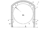
FIG. 4 is a plan view illustrating the partition plate according to the second embodiment. Note that the schematic configuration of the FOUP 1 is the same as that of the first embodiment described above, and will be described here with reference to only a plan view.
本実施例に係るFOUP1は、基板Wとは異なる板状部材21を仕切り板DP2として用いている点において上述した実施例1と相違する。
The FOUP 1 according to the present embodiment is different from the first embodiment described above in that a plate-
板状部材21の材料としては、例えば、ポリカーボネート製の薄板が挙げられる。材料としては、ポリカーボネートに限定されるものではなく、基板Wに悪影響を与えないものであれば他のものでもよい。また、板状部材21の厚さは、支持溝13に載置でき、かつ、支持溝13に載置した際に湾曲して、下方の基板Wに接触しない強度を備えている。板状部材21は、内部空間5の内壁に当接する端面eg1と、内部空間5の内壁に当接せず離間した端面eg2とを有する。なお、ここでいう内部空間5の内壁は、内部空間5の内壁に設けられた支持部9や当接部11を含む。
Examples of the material of the
具体的には、左右の端面eg1及び後側の端面eg1は、支持溝13または当接部11に当接し、後側の角部にあたる端面eg2は、内部空間5のうち奥側角の内壁から離間している。これは、FOUP1の奥側の形状が異なるものであっても板状部材21が仕切り板DP2として載置できるようにするためである。なお、板状部材21は、その前側の端面eg3の位置が、蓋17が開口部7に装着された際に、蓋17で強く押圧されない寸法にしてある。蓋17が開口部7に装着されると、基板Wを蓋17で押し込み、基板Wの後側端面を当接部11に押し当てることにより、基板WをFOUP1内で固定するが、この動作を妨げないようにするためである。
Specifically, the left and right end surfaces eg1 and the rear end surface eg1 are in contact with the
本実施例によると、上述した実施例1と同様に収容器本体3の内部空間5を複数の雰囲気(上記の第1の空間SP1,第2の空間SP2)に仕切ることができるので、基板の相互汚染を抑制することができる。
According to the present embodiment, the
また、本実施例は、基板Wとは異なる板状部材21で仕切り板DP2を構成し、板状部材21は、内部空間5の内壁に当接する端面eg1と、内部空間5の内壁から離間する端面eg2とを有する。したがって、板状部材21の形状に応じて、雰囲気を仕切る度合いを所望の度合いにすることができる。
Further, in this embodiment, the partition plate DP <b> 2 is configured by a plate-
また、本実施例の仕切り板DP2は、固定的にFOUP1に取り付けることも可能であるので、仕切り板DP2の装着忘れによる基板の相互汚染を防止することができる。 In addition, since the partition plate DP2 of this embodiment can be fixedly attached to the FOUP 1, it is possible to prevent mutual contamination of the substrates due to forgetting to install the partition plate DP2.
次に、図面を参照して本発明の実施例3を説明する。
図5は、実施例3に係る仕切り板を示す平面図である。なお、FOUP1の概略構成は、上述した実施例1と同様であるので、ここでは平面図だけを参照して説明する。
Next,
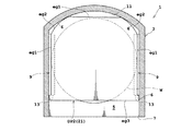
FIG. 5 is a plan view illustrating the partition plate according to the third embodiment. Note that the schematic configuration of the FOUP 1 is the same as that of the first embodiment described above, and will be described here with reference to only a plan view.
本実施例に係るFOUP1は、基板Wとは異なる板状部材21を仕切り板DP3として用いている点において上述した実施例1と相違し、上述した実施例2と似た構成である。
The FOUP 1 according to this embodiment is different from the first embodiment described above in that a plate-
板状部材23の材料や厚み等は、上述した実施例2と同様である。板状部材23は、周囲が内部空間5の内壁に当接する端面eg4を有する。なお、ここでいう内部空間5の内壁は、内部空間5の内壁に設けられた支持部9や当接部11を含む。
The material, thickness, and the like of the plate-
具体的には、左右及び後側の端面eg4は、内部空間5の内壁や、当接部11、支持部9に当接している。また、板状部材23は、その前側の端面eg5の位置が、蓋17で押圧されない寸法にしてあるのは上述した実施例2と同様の理由による。
Specifically, the left and right and rear end faces eg4 are in contact with the inner wall of the
本実施例によると、上述した実施例1と同様に収容器本体3の内部空間5を複数の雰囲気(上記の第1の空間SP1,第2の空間SP2)に仕切ることができるので、基板の相互汚染を抑制することができる。
According to the present embodiment, the
また、内部空間5のうち開口部7を除いた面に当接する端面を備えた板状部材23で仕切り板DP3を構成するので、雰囲気の分離度合いを高くすることができる。したがって、基板の相互汚染の抑制度合いを高くすることができる。
Moreover, since partition plate DP3 is comprised with the plate-shaped
また、本実施例の仕切り板DP3は、固定的にFOUP1に取り付けることも可能であるので、仕切り板DP3の装着忘れによる相互汚染を防止することができる。 Further, since the partition plate DP3 of this embodiment can be fixedly attached to the FOUP 1, it is possible to prevent cross contamination due to forgetting to install the partition plate DP3.
次に、図面を参照して本発明の実施例4を説明する。
図6は、実施例4に係る仕切り板を示す正面図である。なお、FOUP1の概略構成は、上述した実施例1と同様であるので、ここでは正面図だけを参照して説明する。
Next, Embodiment 4 of the present invention will be described with reference to the drawings.
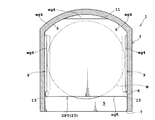
FIG. 6 is a front view illustrating the partition plate according to the fourth embodiment. Note that the schematic configuration of the FOUP 1 is the same as that of the first embodiment described above, and will be described with reference to only the front view.
本実施例に係るFOUP1は、基板Wとは異なる板状部材25を仕切り板DP4として用いている点において上述した実施例1と相違している。
The FOUP 1 according to the present embodiment is different from the first embodiment described above in that a plate-
板状部材25は、縦断面形状が図6の一部拡大図に示すように起伏状に形成されている。なお、平面図は省略してあるが、板状部材25は、その端面を上述した実施例2または実施例3のようにすればよい。板状部材25の起伏状断面における山谷部分の高さは、支持溝13に載置できる高さである。さらに、板状部材25は、支持溝13に載置した際に湾曲して、下方の基板Wに接触しない強度を備えている。起伏状の形状は、図6のような正弦波状に限定されるものではなく、矩形波、三角波、脈流状であってもよい。
The plate-
本実施例によると、上述した実施例1と同様に収容器本体3の内部空間5を複数の雰囲気(上記の第1の空間SP1,第2の空間SP2)に仕切ることができるので、基板の相互汚染を抑制することができる。
According to the present embodiment, the
また、板状部材25の縦断面形状を起伏状に構成しているので、仕切り板DP4の上方に載置された基板Wからパーティクルが落下したとしても、山谷部分でパーティクルが移動しづらくできる。したがって、落下したパーティクルが搬送中に仕切り板DP4を移動して、他の基板Wを汚染するような相互汚染を抑制することができる。
Moreover, since the longitudinal cross-sectional shape of the plate-
<第1の変形例>
ここで図7を参照して、上述した実施例2の変形例について説明する。図7は、第1の変形例を示す平面図である。なお、以下の説明においては、仕切り板DP2aだけを示して説明する。
<First Modification>
Here, with reference to FIG. 7, the modification of Example 2 mentioned above is demonstrated. FIG. 7 is a plan view showing a first modification. In the following description, only the partition plate DP2a is shown and described.
この仕切り板DP2aは、上述した実施例2における仕切り板DP2に一つの貫通穴31を設けたものである。一つの貫通穴31は、平面視で板状部材21aの中心部に形成されている。
This partition plate DP2a is obtained by providing one through
この第1の変形例は、平面視で中心部に一つの貫通穴31を形成してあるので、板状部材21aの軽量化を図ることができる。貫通穴31は、板状部材21aの中心部にだけ形成されているので、基板Wの下面と支持溝13との摺動によってパーティクルが発生しても、貫通穴31を通してパーティクルが落下することによる基板の相互汚染は抑制できる。また、不活性ガスなどを注入する際に、仕切られた複数の雰囲気にも貫通穴31を通して不活性ガスを送り込むことができる。さらに、貫通穴31の形状や位置を適宜に変えることにより、不活性ガスの気流を調整することができる。なお、ここでいう中心部とは、板状部材21aの中心及び中心に近い部分をいう。
In the first modified example, since one through
<第2の変形例>
ここで図8を参照して、上述した実施例2の変形例について説明する。図8は、第2の変形例を示す平面図である。なお、以下の説明においては、仕切り板DP2bだけを示して説明する。
<Second Modification>
Here, with reference to FIG. 8, the modification of Example 2 mentioned above is demonstrated. FIG. 8 is a plan view showing a second modification. In the following description, only the partition plate DP2b is shown and described.
この仕切り板DP2bは、上述した実施例2における仕切り板DP2に複数個の貫通穴33を設けたものである。ここでは、一例として、25個の貫通孔33が、平面視で板状部材21bの中心領域に形成されている。
This partition plate DP2b is obtained by providing a plurality of through
この第2の変形例は、複数個の小さな貫通孔33により板状部材21bの軽量化を図ることができる。複数個の小さな貫通孔33は、平面視で板状部材21bの中心領域にのみ形成されているので、基板Wの端面と支持溝13との摺動によってパーティクルが発生しても、貫通孔33からパーティクルが落下することによる基板の相互汚染を抑制できる。また、不活性ガスなどを注入する際に、仕切られた複数の雰囲気にも不活性ガスを送り込むことができる。さらに、貫通孔33の形状と数と位置を適宜に変えることにより、不活性ガスの気流を調整することができる。
In the second modification, the plate-
<第3の変形例>
ここで図9,図10を参照して、上述した実施例2の変形例について説明する。図9は、第3の変形例を示す平面図であり、図10は、第3の変形例を示す縦断面図である。
<Third Modification>
Here, with reference to FIG. 9, FIG. 10, the modification of Example 2 mentioned above is demonstrated. FIG. 9 is a plan view showing a third modification, and FIG. 10 is a longitudinal sectional view showing the third modification.
この仕切り板DP2cは、三枚の板状部材21b、21c、21dを備えている。板状部材21bは、平面視で中央領域に複数個の貫通孔33を形成されている。また、板状部材21cは、平面視で奥側に複数個の貫通孔33を形成され、板状部材21dは、平面視で手前側に複数個の貫通孔33を形成されている。仕切り板DP2cは、図10に示すように、下から板状部材21d、板状部21b、板状部材21cの順で配置され、支持部材35によって離間して支持されている。この離間距離は、支持溝13の間隔に設定されている。したがって、三枚の板状部材21b、21c、21dを備えた仕切り板DP2cであっても、支持部9に装着することができる。
The partition plate DP2c includes three plate-
この第3の変形例によると、3枚の板状部材21b、21c、21dを支持部材35で離間させて仕切り板DP2cが構成されているので、雰囲気の分離度合いを高くすることができる。さらに、3枚の板状部材21b、21c、21dは複数個の貫通孔33が形成されているので、板状部材21b、21c、21dが3枚であっても重量の増加を抑制することができる。その上、各板状部材21b、21c、21dの貫通孔33は、平面視で板状部材ごとに異なる領域に形成されているので、パーティクル等が上から下に落下しづらくできる。したがって、貫通孔33を介しての基板の相互汚染を抑制できる。また、不活性ガスなどを注入する際に、仕切られた複数の雰囲気にも不活性ガスを送り込むことができる。
According to the third modification, the partition plate DP2c is configured by separating the three plate-
なお、板状部材21b、21c、21dの三枚で仕切り板DP2cを構成するのではなく、二枚の板状部材や、4枚以上の板状部材で仕切り板DP2cを構成してもよい。また、貫通孔33の形状と数と位置を適宜に変えることにより、不活性ガスの気流を調整することができる。
Note that the partition plate DP2c may be formed by two plate members or four or more plate members instead of the partition plate DP2c by the three
<FOUPの変形例>
ところで、上述したFOUP1は、次のような構成であってもよい。ここで、図11を参照する。図11は、FOUPの変形例を示す一部破断縦断面図である。
<Modification of FOUP>
By the way, the FOUP 1 described above may have the following configuration. Reference is now made to FIG. FIG. 11 is a partially broken longitudinal sectional view showing a modified example of the FOUP.
このFOUP1は、収容器本体3の底部に圧入部41と排気部43とを備えている。圧入部41と排気部43とは、内部空間5の圧力と外部圧力とを一定に保つブレスフィルタ(図示省略)を備え、FOUP1の搬送中に大気圧が変化してもFOUP1の収縮や膨張を防ぐことができる。また、圧入部41からパーティクルが内部空間5に侵入するのを防止する。
The FOUP 1 includes a press-
FOUP1が載置されるロードポート(図示省略)は、ガス供給部51と強制排気部53とを備えている。ガス供給部51は、気体を所定の圧力で供給する機能を有する。気体としては、不活性ガス、例えば、窒素ガスが挙げられる。強制排気部53は、真空ポンプや真空イジェクタ(Vacuum ejector)によって、内部空間5内の気体を強制的に排出する機能を有する。
A load port (not shown) on which the FOUP 1 is placed includes a
FOUP1は、ガス供給部51から窒素ガスを供給されるとともに、強制排気部53により内部空間5の気体が排出される、いわゆる窒素ガスパージが行われることがある。この窒素ガスパージは、FOUP1内の基板Wが搬送される際に、水分やケミカルガスによる汚染から保護するために行われる。
The FOUP 1 may be subjected to a so-called nitrogen gas purge in which nitrogen gas is supplied from the
このような窒素ガスパージを行う場合、上述した実施例1〜4は、内部空間5を仕切り板DP1〜4で仕切っているので、窒素ガスの使用量を低減することができる。
When performing such nitrogen gas purging, in Examples 1 to 4 described above, since the
本発明は、上記実施形態に限られることはなく、下記のように変形実施することができる。 The present invention is not limited to the above embodiment, and can be modified as follows.
(1)上述した各実施例1〜4では、第1の空間SP1と第2の空間SP2の二つに内部空間5を仕切ることを例示した。しかし、本発明は、二枚以上の仕切り板によって内部空間5を三つ以上に仕切るようにしてもよい。
(1) In the first to fourth embodiments described above, the
(2)上述した各実施例1〜4及び第1〜第3変形例では、既存のFOUP1に仕切り板を取り付けるように説明したが、複数の支持溝13のうちのいずれかに代えて仕切り板を一体的に形成した支持部9を採用してもよい。これにより仕切り板の装着忘れによる基板の相互汚染を防止できる。
(2) In each of the first to fourth embodiments and the first to third modifications described above, it has been described that the partition plate is attached to the existing FOUP 1, but the partition plate is replaced with any one of the plurality of
1 … FOUP
3 … 収容器本体
5 … 内部空間
7 … 開口部
9 … 支持部
13 … 支持溝
17 … 蓋
21 … 板状部材
DP1 … 仕切り板
SP1 … 第1の空間
SP2 … 第2の空間
1 ... FOUP
DESCRIPTION OF
Claims (10)
内部空間を有する収容器本体と、
前記収容器本体に形成され、前記内部空間に連通した開口部と、
前記収容器本体の内壁に設けられ、基板の端縁下面を当接支持する複数の支持溝と、
前記開口部に着脱自在の蓋と、
前記複数の支持溝に着脱自在に装着されて、前記内部空間を複数の雰囲気に仕切る仕切り板と、
を備えていることを特徴とする基板収容器。 In a substrate container that accommodates a plurality of substrates,
A container body having an internal space;
An opening formed in the container body and communicating with the internal space;
A plurality of support grooves provided on the inner wall of the container body, and abuttingly supporting the lower surface of the edge of the substrate;
A detachable lid on the opening;
A partition plate that is detachably attached to the plurality of support grooves and divides the internal space into a plurality of atmospheres;
A substrate container characterized by comprising:
前記仕切り板は、ダミー基板であることを特徴とする基板収容器。 The substrate container according to claim 1, wherein
The substrate container is characterized in that the partition plate is a dummy substrate.
前記仕切り板は、基板とは異なる板状部材で構成されていることを特徴とする基板収容器。 The substrate container according to claim 1, wherein
The board | substrate container characterized by the said partition plate being comprised with the plate-shaped member different from a board | substrate.
前記仕切り板は、基板とは異なる板状部材で構成され、
前記板状部材は、内部空間の内壁に当接する端面と、内部空間の内壁から離間した端面とを備えていることを特徴とする基板収容器。 The substrate container according to claim 1, wherein
The partition plate is composed of a plate-like member different from the substrate,
The plate-like member is provided with an end surface that abuts against an inner wall of the internal space, and an end surface spaced from the inner wall of the internal space.
前記仕切り板は、基板とは異なる板状部材で構成され、
前記板状部材は、周囲が内部空間の内壁に当接する端面を備えていることを特徴とする基板収容器。 The substrate container according to claim 1, wherein
The partition plate is composed of a plate-like member different from the substrate,
The board-like container is characterized in that the plate-like member has an end surface that is in contact with the inner wall of the internal space.
前記板状部材は、縦断面形状が起伏状に構成されていることを特徴とする基板収容器。 The substrate container according to any one of claims 3 to 5,
The board-shaped container is characterized in that the plate-like member is formed in a undulating shape in longitudinal section.
前記板状部材は、平面視で中心部に一つの貫通穴が形成されていることを特徴とする基板収容器。 The substrate container according to any one of claims 3 to 5,
The board container is characterized in that the plate-like member has one through hole formed in a central portion in plan view.
前記板状部材は、平面視で中心領域に複数個の小さな貫通孔が形成されていることを特徴とする基板収容器。 The substrate container according to any one of claims 3 to 5,
The plate-like member has a plurality of small through holes formed in a central region in a plan view.
前記仕切り板は、複数枚の板状部材と、前記複数の支持溝の間隔で前記各板状部材を支持する支持部材とを備え、
前記複数枚の板状部材は、複数個の小さな貫通孔が形成されており、
前記複数個の小さな貫通孔は、平面視で、前記板状部材ごとに異なる領域に形成されていることを特徴とする基板収容器。 The substrate container according to claim 1, wherein
The partition plate includes a plurality of plate-like members and a support member that supports the plate-like members at intervals of the plurality of support grooves,
The plurality of plate-like members are formed with a plurality of small through holes,
The plurality of small through holes are formed in different regions for each plate member in plan view.
前記収容器本体は、前記内部空間の圧力と外部圧力とを一定に保つ機能を備えた吸入部と排気部とを備え、
前記吸入部から不活性ガスを圧入されるとともに、前記排気部から前記内部空間内の気体が強制的に排気されることを特徴とする基板収容器。 The substrate container according to any one of claims 1 to 9,
The container body includes a suction part and an exhaust part having a function of keeping the pressure of the internal space and the external pressure constant,
An inert gas is press-fitted from the suction part, and the gas in the internal space is forcibly exhausted from the exhaust part.
Priority Applications (1)
| Application Number | Priority Date | Filing Date | Title |
|---|---|---|---|
| JP2011061155A JP5797430B2 (en) | 2011-03-18 | 2011-03-18 | Substrate container |
Applications Claiming Priority (1)
| Application Number | Priority Date | Filing Date | Title |
|---|---|---|---|
| JP2011061155A JP5797430B2 (en) | 2011-03-18 | 2011-03-18 | Substrate container |
Publications (2)
| Publication Number | Publication Date |
|---|---|
| JP2012199302A true JP2012199302A (en) | 2012-10-18 |
| JP5797430B2 JP5797430B2 (en) | 2015-10-21 |
Family
ID=47181261
Family Applications (1)
| Application Number | Title | Priority Date | Filing Date |
|---|---|---|---|
| JP2011061155A Expired - Fee Related JP5797430B2 (en) | 2011-03-18 | 2011-03-18 | Substrate container |
Country Status (1)
| Country | Link |
|---|---|
| JP (1) | JP5797430B2 (en) |
Cited By (3)
| Publication number | Priority date | Publication date | Assignee | Title |
|---|---|---|---|---|
| JP2015177165A (en) * | 2014-03-18 | 2015-10-05 | ダイセル・エボニック株式会社 | Front opening shipping box and manufacturing method therefor |
| JP2017092459A (en) * | 2015-10-20 | 2017-05-25 | ラム リサーチ コーポレーションLam Research Corporation | Wafer transport assembly with integrated buffers |
| JP2020145333A (en) * | 2019-03-07 | 2020-09-10 | 東京エレクトロン株式会社 | Storage container partition plate, storage container, substrate processing system, and substrate transport method |
Citations (8)
| Publication number | Priority date | Publication date | Assignee | Title |
|---|---|---|---|---|
| JPS63178541A (en) * | 1987-01-20 | 1988-07-22 | Nec Corp | Housing for wafer |
| JPH07117811A (en) * | 1993-10-22 | 1995-05-09 | Ebara Corp | Shielding structure of base plate and shielding method |
| JP2003297913A (en) * | 2002-03-29 | 2003-10-17 | Hoya Corp | Medicine retainer and photomask blank receiving vessel |
| JP2004221227A (en) * | 2003-01-14 | 2004-08-05 | Hitachi Kokusai Electric Inc | Substrate treating apparatus |
| JP2004260087A (en) * | 2003-02-27 | 2004-09-16 | Shin Etsu Polymer Co Ltd | Storing container |
| JP2005353862A (en) * | 2004-06-11 | 2005-12-22 | Sony Corp | Substrate storing and carrying container |
| JP2006114761A (en) * | 2004-10-15 | 2006-04-27 | Renesas Technology Corp | Wafer container |
| JP2006350231A (en) * | 2005-06-20 | 2006-12-28 | Shin Etsu Chem Co Ltd | Large pellicle housing container for lithography |
-
2011
- 2011-03-18 JP JP2011061155A patent/JP5797430B2/en not_active Expired - Fee Related
Patent Citations (8)
| Publication number | Priority date | Publication date | Assignee | Title |
|---|---|---|---|---|
| JPS63178541A (en) * | 1987-01-20 | 1988-07-22 | Nec Corp | Housing for wafer |
| JPH07117811A (en) * | 1993-10-22 | 1995-05-09 | Ebara Corp | Shielding structure of base plate and shielding method |
| JP2003297913A (en) * | 2002-03-29 | 2003-10-17 | Hoya Corp | Medicine retainer and photomask blank receiving vessel |
| JP2004221227A (en) * | 2003-01-14 | 2004-08-05 | Hitachi Kokusai Electric Inc | Substrate treating apparatus |
| JP2004260087A (en) * | 2003-02-27 | 2004-09-16 | Shin Etsu Polymer Co Ltd | Storing container |
| JP2005353862A (en) * | 2004-06-11 | 2005-12-22 | Sony Corp | Substrate storing and carrying container |
| JP2006114761A (en) * | 2004-10-15 | 2006-04-27 | Renesas Technology Corp | Wafer container |
| JP2006350231A (en) * | 2005-06-20 | 2006-12-28 | Shin Etsu Chem Co Ltd | Large pellicle housing container for lithography |
Cited By (7)
| Publication number | Priority date | Publication date | Assignee | Title |
|---|---|---|---|---|
| JP2015177165A (en) * | 2014-03-18 | 2015-10-05 | ダイセル・エボニック株式会社 | Front opening shipping box and manufacturing method therefor |
| JP2017092459A (en) * | 2015-10-20 | 2017-05-25 | ラム リサーチ コーポレーションLam Research Corporation | Wafer transport assembly with integrated buffers |
| JP7020772B2 (en) | 2015-10-20 | 2022-02-16 | ラム リサーチ コーポレーション | Wafer transfer assembly with integrated buffer |
| US11393705B2 (en) | 2015-10-20 | 2022-07-19 | Lam Research Corporation | Wafer transport assembly with integrated buffers |
| US11764086B2 (en) | 2015-10-20 | 2023-09-19 | Lam Research Corporation | Wafer transport assembly with integrated buffers |
| JP2020145333A (en) * | 2019-03-07 | 2020-09-10 | 東京エレクトロン株式会社 | Storage container partition plate, storage container, substrate processing system, and substrate transport method |
| JP7357453B2 (en) | 2019-03-07 | 2023-10-06 | 東京エレクトロン株式会社 | Substrate processing system and substrate transport method |
Also Published As
| Publication number | Publication date |
|---|---|
| JP5797430B2 (en) | 2015-10-21 |
Similar Documents
| Publication | Publication Date | Title |
|---|---|---|
| JP4251580B1 (en) | Containment transport system | |
| KR101024530B1 (en) | Substrate processing apparatus, substrate processing method, and computer-readable storage medium | |
| JP4789566B2 (en) | Thin plate holding container and processing device for thin plate holding container | |
| TWI526377B (en) | Wafer transport pod | |
| JP2010129769A (en) | Substrate processing system | |
| JP2007281053A (en) | Thin plate housing container | |
| JP5797430B2 (en) | Substrate container | |
| US8413815B2 (en) | Wafer container with at least one purgeable supporting module having a long slot | |
| WO2007114331A1 (en) | Thin plate container | |
| JP2008100805A (en) | Substrate storage warehouse | |
| US7938269B2 (en) | Ventilated front-opening unified pod | |
| JP5456804B2 (en) | Transport container | |
| KR20160033604A (en) | Cover opening/closing apparatus and cover opening/closing method | |
| JP7458212B2 (en) | Board transport system and board transport method | |
| JP2007180108A (en) | Method of taking out/putting in plate from plate holding container | |
| JP5465979B2 (en) | Semiconductor manufacturing equipment | |
| JP6027837B2 (en) | Substrate processing apparatus and semiconductor device manufacturing method | |
| CN107689336B (en) | Cover and substrate processing apparatus using the same | |
| JP4415006B2 (en) | Cassette operation management method and substrate processing method | |
| JP5749002B2 (en) | Load lock device and vacuum processing device | |
| JP2010161157A (en) | Substrate storing method and storage medium | |
| JP2005347667A (en) | Semiconductor fabrication device | |
| KR102457336B1 (en) | Substrate processing apparatus | |
| JP2012134370A (en) | Chamber, vacuum processing apparatus, substrate transfer method | |
| JP2013051267A (en) | Tank carrier and substrate processing apparatus |
Legal Events
| Date | Code | Title | Description |
|---|---|---|---|
| A621 | Written request for application examination |
Free format text: JAPANESE INTERMEDIATE CODE: A621 Effective date: 20140303 |
|
| A977 | Report on retrieval |
Free format text: JAPANESE INTERMEDIATE CODE: A971007 Effective date: 20150107 |
|
| A131 | Notification of reasons for refusal |
Free format text: JAPANESE INTERMEDIATE CODE: A131 Effective date: 20150127 |
|
| A521 | Written amendment |
Free format text: JAPANESE INTERMEDIATE CODE: A523 Effective date: 20150209 |
|
| TRDD | Decision of grant or rejection written | ||
| A01 | Written decision to grant a patent or to grant a registration (utility model) |
Free format text: JAPANESE INTERMEDIATE CODE: A01 Effective date: 20150807 |
|
| A61 | First payment of annual fees (during grant procedure) |
Free format text: JAPANESE INTERMEDIATE CODE: A61 Effective date: 20150819 |
|
| R150 | Certificate of patent or registration of utility model |
Ref document number: 5797430 Country of ref document: JP Free format text: JAPANESE INTERMEDIATE CODE: R150 |
|
| LAPS | Cancellation because of no payment of annual fees |