JP2012197896A - Vehicle control apparatus, vehicle, and motor - Google Patents
Vehicle control apparatus, vehicle, and motor Download PDFInfo
- Publication number
- JP2012197896A JP2012197896A JP2011063195A JP2011063195A JP2012197896A JP 2012197896 A JP2012197896 A JP 2012197896A JP 2011063195 A JP2011063195 A JP 2011063195A JP 2011063195 A JP2011063195 A JP 2011063195A JP 2012197896 A JP2012197896 A JP 2012197896A
- Authority
- JP
- Japan
- Prior art keywords
- value
- clutch
- torque
- engine
- torque capacity
- Prior art date
- Legal status (The legal status is an assumption and is not a legal conclusion. Google has not performed a legal analysis and makes no representation as to the accuracy of the status listed.)
- Granted
Links
Images


Classifications
-
- Y—GENERAL TAGGING OF NEW TECHNOLOGICAL DEVELOPMENTS; GENERAL TAGGING OF CROSS-SECTIONAL TECHNOLOGIES SPANNING OVER SEVERAL SECTIONS OF THE IPC; TECHNICAL SUBJECTS COVERED BY FORMER USPC CROSS-REFERENCE ART COLLECTIONS [XRACs] AND DIGESTS
- Y02—TECHNOLOGIES OR APPLICATIONS FOR MITIGATION OR ADAPTATION AGAINST CLIMATE CHANGE
- Y02T—CLIMATE CHANGE MITIGATION TECHNOLOGIES RELATED TO TRANSPORTATION
- Y02T10/00—Road transport of goods or passengers
- Y02T10/60—Other road transportation technologies with climate change mitigation effect
Abstract
Description
本発明は、車両の制御装置、車両及び原動機に関し、特には、変速期間中のクラッチ制御に関する。 The present invention relates to a vehicle control device, a vehicle, and a prime mover.
従来、自動二輪車等の車両では、変速期間中にクラッチのトルク容量を調整することでエンジンの回転速度を変化させる回転制御が行われることがある。 Conventionally, in a vehicle such as a motorcycle, rotation control for changing the rotation speed of an engine by adjusting the torque capacity of a clutch during a shift period may be performed.
特許文献1には、ツインクラッチ式の車両が開示されている。ツインクラッチ式の車両では、クラッチ及び変速機構を含む2本の経路が並列に設けられており、エンジンからのトルクを伝達する経路が変速期間中に一方から他方に切り替えられる。この特許文献1の段落0046〜0063及び図8〜図11には、変速期間中にクラッチのトルク容量を調整することでエンジンの回転速度を変化させることが記載されている。
ところで、アクチュエータがプレッシャープレートを駆動する種類のクラッチでは、プレートの摩耗等の要因により、アクチュエータに与える指示値とクラッチに生じるトルク容量との関係が経時的に変化することがある。そこで、上記従来の車両では、回転制御の結果に基づいて、アクチュエータの指示値とクラッチのトルク容量との関係を表すテーブル等の情報を適宜更新することが求められている。 By the way, in the type of clutch in which the actuator drives the pressure plate, the relationship between the instruction value given to the actuator and the torque capacity generated in the clutch may change over time due to factors such as plate wear. Therefore, in the conventional vehicle, it is required to appropriately update information such as a table representing the relationship between the instruction value of the actuator and the torque capacity of the clutch based on the result of the rotation control.
しかしながら、車両の運転条件に依っては回転制御の結果が異なることがあるため、更新される情報の精度が高くないおそれがある。例えば、エンジンの出力トルクが上昇中の場合と下降中の場合とでは、クラッチに同じトルク容量が生じてもエンジンの回転速度の変化特性が異なることがある。また、クラッチのトルク容量がヒステリシスを持つ場合等には、アクチュエータに同じ指示値が与えられてもクラッチに生じるトルク容量が異なることがある。 However, since the result of the rotation control may vary depending on the driving conditions of the vehicle, the accuracy of the updated information may not be high. For example, when the output torque of the engine is increasing and when it is decreasing, even if the same torque capacity is generated in the clutch, the change characteristic of the engine rotational speed may be different. Further, when the torque capacity of the clutch has hysteresis, the torque capacity generated in the clutch may be different even if the same instruction value is given to the actuator.
本発明は、上記実情に鑑みて為されたものであり、車両の運転条件に応じたアクチュエータの指示値とクラッチのトルク容量との関係を表す情報を得ることが可能な車両の制御装置、車両及び原動機を提供することを主な目的とする。 The present invention has been made in view of the above circumstances, and is a vehicle control device and a vehicle capable of obtaining information representing a relationship between an instruction value of an actuator and a torque capacity of a clutch in accordance with a driving condition of the vehicle. The main purpose is to provide a prime mover.
上記課題を解決するため、本発明の制御装置は、エンジンから出力されるトルクを伝達する経路に、アクチュエータの動作に応じてトルク容量が変化するクラッチと、前記クラッチの下流に配置されるドッグクラッチ式の変速機構と、を備える車両に設けられる。前記制御装置は、変速期間中に、前記エンジンの出力トルクに対して前記クラッチのトルク容量が大きく又は小さくなるように前記アクチュエータに指示値を与えて、前記エンジンの回転速度を変化させる回転制御を実行する。また、前記制御装置は、保持部と、判定部と、決定部と、制御部と、更新部と、を備える。前記保持部は、前記トルク容量と前記アクチュエータの指示値との関係を表す条件別情報を保持する。前記条件別情報は、前記アクチュエータに同じ指示値が与えられても前記クラッチに生じるトルク容量が異なる複数の運転条件、又は、前記クラッチに同じトルク容量が生じても前記エンジンの回転速度の変化特性が異なる複数の運転条件の各々において適用される。前記判定部は、前記複数の運転条件の何れの運転条件で変速が行われるかを判定する。前記決定部は、前記判定された運転条件で適用される前記条件別情報に基づいて、前記トルク容量の目標値に対応する前記アクチュエータの指示値を決定する。前記制御部は、前記決定された指示値を前記アクチュエータに与えて、前記エンジンの回転速度を変化させる。前記更新部は、前記エンジンの回転速度を変化させた期間に生じた前記トルク容量の実績値と目標値との関係を表す情報に基づいて、前記判定された運転条件で適用される前記条件別情報を更新する。 In order to solve the above-described problems, a control device according to the present invention includes a clutch whose torque capacity changes according to the operation of an actuator on a path for transmitting torque output from an engine, and a dog clutch disposed downstream of the clutch. And a transmission mechanism of the type. The control device performs a rotation control to change an engine rotation speed by giving an instruction value to the actuator so that a torque capacity of the clutch is increased or decreased with respect to an output torque of the engine during a shift period. Execute. The control device includes a holding unit, a determination unit, a determination unit, a control unit, and an update unit. The holding unit holds condition-specific information representing a relationship between the torque capacity and the indicated value of the actuator. The condition-specific information includes a plurality of operating conditions in which the torque capacity generated in the clutch is different even when the same instruction value is given to the actuator, or a change characteristic of the rotational speed of the engine even if the same torque capacity is generated in the clutch. Is applied in each of a plurality of different operating conditions. The determination unit determines which of the plurality of driving conditions is used for shifting. The determination unit determines an instruction value of the actuator corresponding to a target value of the torque capacity based on the condition-specific information applied under the determined operating condition. The controller gives the determined instruction value to the actuator to change the rotational speed of the engine. The update unit is configured to apply the determined operation condition according to the condition based on information representing a relationship between the actual value and the target value of the torque capacity generated during a period in which the rotation speed of the engine is changed. Update information.
また、本発明の車両は、上記制御装置を備える。 Moreover, the vehicle of this invention is provided with the said control apparatus.
また、本発明の原動機は、上記制御装置を備える。 Moreover, the motor | power_engine of this invention is provided with the said control apparatus.
上記本発明によると、車両の運転条件に応じたアクチュエータの指示値とクラッチのトルク容量との関係を表す情報を得ることが可能である。 According to the present invention, it is possible to obtain information representing the relationship between the indicated value of the actuator and the torque capacity of the clutch according to the driving conditions of the vehicle.
本発明の車両の制御装置、車両及び原動機の実施形態を、図面を参照しながら説明する。 DESCRIPTION OF EMBODIMENTS Embodiments of a vehicle control device, a vehicle, and a prime mover of the present invention will be described with reference to the drawings.
図1は、本発明の一実施形態に係る制御装置10を備えた自動二輪車1の側面図である。図2は、エンジン20から後輪3に至るトルク伝達経路に設けられた機構の概略図である。図3は、本発明の車両の一実施形態である自動二輪車1の構成を示すブロック図である。
FIG. 1 is a side view of a
図1に示すように、自動二輪車1は、本発明の原動機の一実施形態であるエンジンユニット11を備えている。エンジンユニット11の前方に配置される前輪2は、フロントフォーク4の下端で支持されている。フロントフォーク4の上部には車体フレーム(不図示)の最前部で回転可能に支持されたステアリングシャフト5が連結されている。ステアリングシャフト5の上方にはステアリング6が設けられている。ステアリング6とフロントフォーク4と前輪2は、ステアリングシャフト5を中心にして一体的に左右に回転可能となっている。
As shown in FIG. 1, a
ステアリング6の後方には搭乗者が跨って座ることのできるシート7が配置されている。エンジンユニット11の後方には後輪3が配置されている。変速機30(図2参照)から出力されるトルクはチェーンやベルト、ドライブシャフトなどのトルク伝達部材(不図示)を介して後輪3に伝達される。
A seat 7 on which a passenger can sit across is disposed behind the steering 6. A rear wheel 3 is disposed behind the
図2に示すように、エンジンユニット11はエンジン20と変速機30とを備えている。自動二輪車1は所謂ツインクラッチ式の車両であり、第1クラッチ40Aと第2クラッチ40Bとがエンジンユニット11に設けられている。エンジン20はその駆動によって回転するクランクシャフト21を備えている。
As shown in FIG. 2, the
エンジン20のトルク(クランクシャフト21の回転)は、第1クラッチ40Aと第2クラッチ40Bのそれぞれに入力される。第1クラッチ40Aと第2クラッチ40Bは、クランクシャフト21の回転に連動する駆動部材41を有している。図2に示す例では、クランクシャフト21は2つのプライマリギア21aを有している。第1クラッチ40Aの駆動部材41と第2クラッチ40Bの駆動部材41とにはプライマリギア41aが設けられている。プライマリギア41aはプライマリギア21aと噛み合っている。
The torque of the engine 20 (rotation of the crankshaft 21) is input to each of the first clutch 40A and the second clutch 40B. The first clutch 40 </ b> A and the second clutch 40 </ b> B have a
第1クラッチ40Aと第2クラッチ40Bは、後述する変速機構30A,30Bの入力軸31に連動する従動部材42を有している。第1クラッチ40Aと第2クラッチ40Bは例えば単板又は多板の摩擦クラッチである。駆動部材41と従動部材42が互いに軸方向で押し付けられることにより、それらの間でトルクの伝達がなされる。なお、駆動部材41は例えばフリクションディスクであり、従動部材42は例えばクラッチディスクである。
The first clutch 40A and the second clutch 40B have a driven
変速機30は第1変速機構30Aと第2変速機構30Bとを備えている。第1変速機構30Aと第2変速機構30Bは第1クラッチ40Aと第2クラッチ40Bの下流にそれぞれ配置されている。すなわち、第1変速機構30Aと第2変速機構30Bのそれぞれに入力軸31が設けられている。第1変速機構30Aの入力軸31は第1クラッチ40Aの従動部材42に連結されており、第1変速機構30Aには第1クラッチ40Aを介してトルクが入力される。第2変速機構30Bの入力軸31は第2クラッチ40Bの従動部材42に連結され、第2変速機構30Bには第2クラッチ40Bを介してトルクが入力される。第1変速機構30A,30Bは共通の出力軸32を有している。このように、自動二輪車1はエンジン20のクランクシャフト21から変速機30の出力軸32に至るトルク伝達経路として2つの経路を有している。第1の経路は、第1変速機構30Aと第1クラッチ40Aとによって構成され、第2の経路は第2変速機構30Bと第2クラッチ40Bとによって構成される。変速機30の出力軸32は、チェーンやベルト、シャフトなどで構成されたトルク伝達部材介して後輪3の車軸に連結されている。
The
第1変速機構30Aと第2変速機構30Bは複数のギア1i〜6i及び1h〜6hを含んでいる。ギア1i〜6iは入力軸31に設けられ、ギア1h〜6hは出力軸32に設けられている。ギア1iとギア1hは互いに噛み合っており、それらの減速比は1速に対応している。同様に、ギア2i乃至6iはギア2h乃至6hとそれぞれ噛み合っており、それらの減速比は2速乃至6速にそれぞれ対応している。この例では、第1変速機構30Aは奇数変速段に対応するギア1i,3i,5i,1h,3h,5hによって構成され、第2変速機構30Bは偶数変速段に対応するギア2i、4i,6i,2h,4h,6hによって構成されている。
The
変速機構30A,30Bは所謂選択摺動式の変速機構である。各変速段に対応したギア対(例えば、ギア1iとギア1h)のうちいずれか一方は、当該一方のギアが設けられた軸に対して相対回転自在となっている。これに対して、他方のギアは当該他方のギアが設けられた軸とスプラインで噛み合っており、当該軸と一体的に回転する。この例では、ギア1h,5i,3h,4h,6i,2hが、それらのギアが設けられた軸に対して相対回転自在となっている。一方、ギア1i,5h,3i,4i,6h,2iは、それらが設けられた軸と噛み合っており、当該軸と一体的に回転する。そのため、中立状態(いずれの変速段にも設定されていない状態)においては、ギア対(5i,5h)及び(6i,6h)は出力軸32に連動し、ギア対(1i,1h)、(3i,3h)、(4i,4h)及び(2i,2h)は入力軸31に連動する。
The
入力軸31に連動するギアと出力軸32に連動するギアは、軸方向で互いに隣り合うように配置され、且つ、軸方向に相対移動可能(接近方向及び離れる方向への移動が可能)となっている。また、複数のギア1i〜6i,1h〜6hは、ドッグクラッチ(dog clutch)が形成されたギアを含んでいる。入力軸31に連動するギアと出力軸32に連動するギアは、ドッグクラッチによって係合可能となっている。これらの2つのギアの係合によって、第1変速機構30Aの入力軸31又は第2変速機構30Bの入力軸31の回転(トルク)は、出力軸32に伝達される。なお、図2の例では、ギア5h,3i,4i,6hが軸方向に移動可能となっている。
The gears interlocking with the
図2に示すように、変速機30には軸方向に移動可能なギア5h,3i,4i,6h(以下、可動ギア)を軸方向に移動させるシフトアクチュエータ39が設けられている。シフトアクチュエータ39は、可動ギアに引っ掛かる複数のシフトフォーク39aや、回転することによってシフトフォーク39aを軸方向に動かすシフトカム39b、シフトカム39bを回転させる動力を発生する電動モータ39c等を含んでいる。シフトアクチュエータ39は制御装置10による制御の下で可動ギアを動かし、変速段を切り換える。
As shown in FIG. 2, the
クラッチ40A,40Bには、これらを制御装置10による制御の下で動かす(すなわちクラッチ40A,40Bを係合状態にしたり、解放状態にする)クラッチアクチュエータ49A,49Bが設けられている。クラッチアクチュエータ49A,49Bは例えば電動モータを含んでいる。電動モータの動力は、油圧やロッドを介してプレッシャープレート43に伝えられ、駆動部材41と従動部材42とを軸方向で互いに押し付ける。
The
図3に示すように、エンジン20には、燃料噴射装置22とスロットルアクチュエータ23と点火プラグ24とが設けられている。燃料噴射装置22はエンジン20の燃焼室で燃焼させる燃料をエンジン20に供給する。スロットルアクチュエータ23はエンジン20の吸気路を流れる空気量を調整するスロットルバルブ(不図示)の開度を制御する。点火プラグ24はエンジン20の燃焼室に流れ込んだ空気と燃料の混合気に点火する。燃料噴射装置22の燃料噴射量、点火プラグ24の点火タイミング、及び、スロットルバルブの開度(以下、スロットル開度)は制御装置10によって制御される。
As shown in FIG. 3, the
自動二輪車1は、エンジン回転速度センサ19aと、ギア位置センサ19bと、クラッチセンサ19c,19dと、出力側回転センサ19eと、シフトスイッチ19fと、アクセルセンサ19gと、を含んでいる。これらのセンサは制御装置10に接続されている。
The
エンジン回転速度センサ19aはエンジン回転速度に応じた周波数のパルス信号を出力する回転センサによって構成される。制御装置10はエンジン回転速度センサ19aの出力信号に基づいてエンジン回転速度(クランクシャフト21の回転速度)を算出する。
The engine
ギア位置センサ19bは例えばシフトカム39bの回転角に応じた電圧信号を出力するポテンショメータによって構成される。制御装置10はギア位置センサ19bの出力信号に基づいて、可動ギア5h,3i,4i,6hの位置や現在の変速段などを検知する。
The
出力側回転センサ19eは後輪3の車軸や、出力軸32に設けられる。出力側回転センサ19eは、例えば後輪3の回転速度や、出力軸32の回転速度に応じた周波数のパルス信号を出力する回転センサである。制御装置10は出力側回転センサ19eの出力信号に基づいて車速や出力軸32の回転速度を算出する。
The output
シフトスイッチ19fは搭乗者によって操作されるスイッチであり、搭乗者の変速指令(変速段を上げるシフトアップ指令を示す信号、変速段を下げるシフトダウン指令を示す信号)を制御装置10に対して入力する。なお、シフトスイッチ19fはシフトアップ用のスイッチとシフトダウン用のスイッチとが設けられる。
The
アクセルセンサ19gはステアリング6に設けられたアクセルグリップ(不図示)の操作量(回転角)に応じた信号を出力する。アクセルセンサ19gは例えばポテンショメータによって構成される。制御装置10はアクセルセンサ19gの出力信号に基づいてアクセルグリップの操作量(アクセル操作量)を検知する。
The
クラッチセンサ19cは、第1クラッチ40Aの伝達トルク容量(現在の第1クラッチ40Aの状態(現在の係合度合い)で伝達可能な最大トルク)を検出するためのセンサである。また、クラッチセンサ19dは、第2クラッチ40Bの伝達トルク容量(現在の第2クラッチ40Bの状態(現在の係合度合い)で伝達可能な最大トルク)を検出するためのセンサである。クラッチ40A,40Bが係合状態にある時に伝達トルク容量は最大となり、クラッチ40A,40Bが解放状態にある時に伝達トルク容量は最小(例えば0Nm)となる。クラッチセンサ19c,19dは、例えば、プレッシャープレート43の変位量を検出する。
The
伝達トルク容量はクラッチ40A,40Bの位置(クラッチのストローク量)に対応している。クラッチセンサ19c,19dは、例えば、クラッチ40A,40Bの位置に応じた信号(クラッチアクチュエータ49A,49Bの動作量に応じた信号)を出力するポテンショメータである。制御装置10は、クラッチセンサ19c,19dの出力信号に基づいて検知されるクラッチ位置から伝達トルク容量を検知する。例えば、制御装置10は、クラッチ位置と伝達トルク容量とを対応付けるマップや演算式を用いて、検知したクラッチ位置から伝達トルク容量を算出する。
The transmission torque capacity corresponds to the positions of the
クラッチアクチュエータ49A,49Bが油圧によってクラッチ40A,40Bを動かす構造においては、伝達トルク容量はクラッチ40A,40Bに作用する油圧(以下、クラッチ圧)に対応している。そういった構造においては、クラッチセンサ19c,19dはクラッチ圧に応じた信号を出力する油圧センサでもよい。この場合、制御装置10は、クラッチセンサ19c,19dの出力信号に基づいて検知されるクラッチ圧から伝達トルク容量を検知する。例えば、制御装置10は、クラッチ圧と伝達トルク容量とを対応付けるマップや演算式を用いて、検知したクラッチ圧から伝達トルク容量を算出する。
In the structure in which the
また、伝達トルク容量はクラッチアクチュエータ49A,49Bからクラッチ40A,40Bに作用する力(駆動部材41と従動部材42の間に作用する押し付け力)に対応している。クラッチアクチュエータ49A,49Bからクラッチ40A,40Bに作用する力によって、その力を受けている部分(例えば、クラッチ40A,40Bのケースなど)が歪む。そこで、クラッチセンサ19c,19dは、当該クラッチ40A,40Bから力を受ける部分の歪みの大きさに応じた信号を出力する歪みセンサでもよい。その場合、制御装置10は、クラッチセンサ19c,19dの出力信号に基づいて検知する歪みから伝達トルク容量を検知する検知する。例えば、制御装置10は、クラッチの歪みと伝達トルク容量とを対応付けるマップや演算式を用いて、検知した歪みから伝達トルク容量を算出する。
The transmission torque capacity corresponds to the force (pressing force acting between the
制御装置10はCPU(Central Processing Unit)と、ROM(Read Only Memory)やRAM(Random Access Memory)などのメモリとを備えている。制御装置10はメモリに格納されたプログラムをCPUにおいて実行し、エンジン20、変速機30、及びクラッチ40A,40Bを制御する。
The
具体的には、制御装置10は、エンジン20の出力トルクについての目標値(以下において目標エンジントルクとする)を設定し、実際の出力トルクが目標エンジントルクになるようにスロットルアクチュエータ23や燃料噴射装置22、点火プラグ24を駆動する。また、制御装置10は、第1クラッチ40Aの伝達トルク容量と第2クラッチ40Bの伝達トルク容量とについて目標値(以下において目標トルク容量とする)を設定し、実際の伝達トルク容量が目標トルク容量になるように、クラッチアクチュエータ49A,49Bを動かす。さらに、制御装置10は、第1変速機構30A及び第2変速機構30Bで設定される変速段が変速指令に応じたものとなるように、シフトアクチュエータ39を動かす。
Specifically, the
変速制御の概要について説明する。なお、以下の説明において、第1クラッチ40Aと第2クラッチ40Bのうち、変速の前にエンジン20のトルクを伝達しているクラッチを前クラッチとし、他方のクラッチ(すなわち、エンジン20のトルクの伝達を変速指令によって開始するクラッチ)を次クラッチとする。同様に、第1変速機構30Aと第2変速機構30Bのうち、変速の前にエンジン20のトルクを伝達している変速機構を前変速機構とし、他方の変速機構(すなわちエンジン20のトルクの伝達を変速指令によって開始する変速機構)を次変速機構とする。
An outline of the shift control will be described. In the following description, of the first clutch 40A and the second clutch 40B, the clutch that transmits the torque of the
図4は変速制御の概要を説明するための図である。同図においは、図2に示す変速機構30A,30B、クラッチ40A,40Bがさらに簡略化して示されている。同図においてクラッチCpが前クラッチであり、クラッチCnが次クラッチである。また、変速機構Tpが前変速機構であり、変速機構Tnが次変速機構である。また、前変速機構TpのギアGp1は、前の変速段でトルクを伝達している可動ギア(5h、3i、4i、又は6h)を示し、ギアGp2は前の変速段でトルクを伝達している固定ギア(1h、5i、3h、4h、6i、又は2h)を示している。さらに、次変速機構TnのギアGn1は、次の変速段でトルクを伝達する可動ギアを示し、ギアGn2は次の変速段でトルクを伝達する固定ギアを示している。この図では、簡略化のために、1つの可動ギアGp1,Gn1と1つの固定ギアGp2,Gn2が示されている。この図においては、固定ギアGp2,Gn2が出力軸32に固定されており(すなわち出力軸32とスプラインで噛み合っており)、出力軸32と一体的に回転する。可動ギアGp1,Gn1は、出力軸32に対して自由に相対回転できる。また、可動ギアGp1,Gn1は、入力軸31に固定されたギアGp3,Gn3とそれぞれ噛み合っており、ギアGp3,Gn3や入力軸31の回転に連動する。
FIG. 4 is a diagram for explaining the outline of the shift control. In this figure, the
図4(a)に示すように、通常走行においては、2つのクラッチCp,Cnは係合状態(伝達トルク容量が最大の状態)に設定されている。前変速機構Tpにおいては、前の変速段に対応する可動ギアGp1と固定ギアGp2とがドッグクラッチによって係合している。また、次変速機構Tnにおいては全ての可動ギアが中立位置(いずれの固定ギアとも係合しない位置)に配置される。そのため、エンジン20のトルクは、2つのトルク伝達経路のうち一方の経路(前クラッチCp及び前変速機構Tp)を介して、後輪3に向けて伝達されている。他方の経路においては次変速機構Tnにおいてトルク伝達が遮断されている。
As shown in FIG. 4A, in normal running, the two clutches Cp and Cn are set to the engaged state (the state where the transmission torque capacity is maximum). In the front transmission mechanism Tp, the movable gear Gp1 and the fixed gear Gp2 corresponding to the previous gear stage are engaged by a dog clutch. Further, in the next transmission mechanism Tn, all the movable gears are arranged at neutral positions (positions that do not engage any fixed gear). Therefore, the torque of the
変速指令が生じたとき、制御装置10はトルクを伝達する経路を一方から他方に切り換える。すなわち、制御装置10は次変速機構Tnの可動ギアGn1と固定ギアGn2とを係合させ、前変速機構Tpの可動ギアGp1を中立位置にする。具体的には、変速機構Tp,TnとクラッチCp,Cnは、変速制御において次のように動かされる。まず、制御装置10は、図4(b)のS1に示されるように次クラッチCnの係合を解除し、S2に示されるように次変速機構Tnの可動ギアGn1を動かし、隣の固定ギアGn2に係合させる(所謂ドグ係合フェーズ)。その後、制御装置10は、図4(c)のS3に示されるように次クラッチCnを解放状態から係合状態に戻し、それと共に前クラッチCpを解放状態にする(所謂トルクフェーズ)。最後に、制御装置10は、図4(d)のS4に示されるように前変速機構Tpの可動ギアGp1を中立位置まで移動させた後に、前クラッチCpを係合状態にする(所謂ドグ解放フェーズ)。
When a shift command is generated, the
なお、こうした変速制御を実行する際、変速中の後輪3の駆動力の増減(変速ショック)を抑えるために、前クラッチCp又は次クラッチCnの駆動部材41の回転速度と従動部材42の回転速度とを一致させるための回転制御(所謂イナーシャフェーズ)が、トルクフェーズ(図4(c)のS3を参照)の前または後に必要となる場合がある。以下に説明する制御装置10の変速制御の複数の制御モードは、トルクフェーズがイナーシャフェーズの前に行われるものと、イナーシャフェーズがトルクフェーズの前に行われるものと、に大きく分けられる。
When such shift control is executed, the rotational speed of the
図5は、制御装置10の変速制御の複数の制御モードを示す図である。制御装置10は変速制御として4つの制御モードを備えている。第1の制御モードは、アクセルを開いた状態でのシフトアップ制御(パワーオンシフトアップ制御)である。第2の制御モードは、アクセルを開いた状態でのシフトダウン制御(パワーオンシフトダウン制御)である。第3の制御モードは、アクセルを閉じた状態でのシフトアップ制御(パワーオフシフトアップ制御)である。第4の制御モードは、アクセルを閉じた状態でのシフトダウン制御(パワーオフシフトダウン制御)である。
FIG. 5 is a diagram illustrating a plurality of control modes of the shift control of the
以下、各々の制御モードについて説明する。図6A〜図6Dは、各々の制御モードの例を説明するためのタイムチャートである。 Hereinafter, each control mode will be described. 6A to 6D are time charts for explaining an example of each control mode.
[第1の制御モード]
図6Aは、制御装置10が実行する第1の制御モード(パワーオンシフトアップ制御)の例を説明するためのタイムチャートである。同図において、一点鎖線はエンジン回転速度Seを表し、実線はエンジントルクTeを表し、破線は次クラッチCnの伝達トルク容量Tcnを表し、二点鎖線は前クラッチCpの伝達トルク容量Tcpを表している。このうち、破線及び二点鎖線は、伝達トルク容量を一次減速比で除した値となっている。なお、同図では、各々の線を互いに重ならないよう縦又は横方向に僅かにずらしている。この第1の制御モードでは、トルクフェーズとイナーシャフェーズとがこの順に実行される。
[First control mode]
FIG. 6A is a time chart for explaining an example of a first control mode (power-on shift-up control) executed by the
まず、制御装置10は、ドグ係合フェーズを開始する(t1)。具体的には、制御装置10は、次クラッチCnを係合状態から解放状態に変化させる。係合状態とは伝達トルク容量が最大となる状態であり、解放状態とは伝達トルク容量が最小(例えば0Nm)となる状態である。また、制御装置10は、シフトアクチュエータ39を駆動して、次変速機構Tnの可動ギアGn1を固定ギアGn2に向けて移動させる。また、制御装置10は、前クラッチCpを係合状態から半係合状態に変化させる。ここでは、前クラッチCpの伝達トルク容量TcpがエンジントルクTeに対応する値まで下げられる。
First, the
次に、制御装置10は、トルクフェーズを開始して、エンジン20のトルクを伝達する経路を切り換える(t2)。制御装置10は、前クラッチCpを半係合状態から解放状態に変化させ、次クラッチCnを解放状態から半係合状態に変化させる。具体的には、制御装置10は、次クラッチCnの伝達トルク容量TcpをエンジントルクTeに対応する値まで上げる。
Next, the
次に、制御装置10は、イナーシャフェーズを開始して、エンジン回転速度Seを低下させる(t3)。具体的には、制御装置10は、エンジントルクTeを次クラッチCnの伝達トルク容量Tcnより相対的に下げることで、エンジン回転速度Seを低下させる。換言すると、制御装置10は、次クラッチCnの伝達トルク容量TcnをエンジントルクTeより相対的に上げることで、エンジン回転速度Seを低下させる。
Next, the
次に、制御装置10は、ドグ解放フェーズを開始する(t4)。具体的には、制御装置10は、シフトアクチュエータ39を駆動して、前変速機構Tpの可動ギアGp1を中立位置に向けて移動させる。その後、制御装置10は、前クラッチCpと次クラッチCnを係合状態に戻す(t5)。これにより、第1の制御モードに係る変速制御が終了する。
Next, the
[第2の制御モード]
図6Bは、制御装置10が実行する第2の制御モード(パワーオンシフトダウン制御)の例を説明するためのタイムチャートである。以下、上記制御モードと異なる点を主に説明する。この第2の制御モードでは、イナーシャフェーズとトルクフェーズとがこの順に実行される。
[Second control mode]
FIG. 6B is a time chart for explaining an example of the second control mode (power-on shift-down control) executed by the
制御装置10は、ドグ係合フェーズの次に、イナーシャフェーズを開始して、エンジン回転速度Seを増加させる(t2)。具体的には、制御装置10は、エンジントルクTeを前クラッチCpの伝達トルク容量Tcpより相対的に上げることで、エンジン回転速度Seを増加させる。換言すると、制御装置10は、前クラッチCpの伝達トルク容量TcpをエンジントルクTeより相対的に上げることで、エンジン回転速度Seを増加させる。その後、制御装置10は、トルクフェーズとドグ解放フェーズとを実行する。これにより、第2の制御モードに係る変速制御が終了する。
The
[第3の制御モード]
図6Cは、制御装置10が実行する第3の制御モード(パワーオフシフトアップ制御)の例を説明するためのタイムチャートである。以下、上記制御モードと異なる点を主に説明する。この第3の制御モードでは、イナーシャフェーズとトルクフェーズとがこの順に実行される。この第3の制御モードでは、エンジントルクTeが負の値になる。
[Third control mode]
FIG. 6C is a time chart for explaining an example of a third control mode (power-off shift-up control) executed by the
制御装置10は、ドグ係合フェーズの次に、イナーシャフェーズを開始して、エンジン回転速度Seを低下させる(t2)。具体的には、制御装置10は、エンジントルクTeの絶対値を前クラッチCpの伝達トルク容量Tcpより相対的に上げることで(すなわち、エンジントルクTeを下げることで)、エンジン回転速度Seを低下させる。換言すると、制御装置10は、前クラッチCpの伝達トルク容量TcpをエンジントルクTeの絶対値より相対的に下げることで、エンジン回転速度Seを低下させる。その後、制御装置10は、トルクフェーズとドグ解放フェーズとを実行する。これにより、第3の制御モードに係る変速制御が終了する。
The
[第4の制御モード]
図6Dは、制御装置10が実行する第4の制御モード(パワーオフシフトダウン制御)の例を説明するためのタイムチャートである。以下、上記制御モードと異なる点を主に説明する。この第4の制御モードでは、トルクフェーズとイナーシャフェーズとがこの順に実行される。この第4の制御モードでは、エンジントルクTeが負の値になる。
[Fourth control mode]
FIG. 6D is a time chart for explaining an example of a fourth control mode (power-off shift down control) executed by the
次に、制御装置10は、トルクフェーズの次に、イナーシャフェーズを開始して、エンジン回転速度Seを増加させる(t3)。具体的には、制御装置10は、エンジントルクTeの絶対値を次クラッチCnの伝達トルク容量Tcnより相対的に下げることで(すなわち、エンジントルクTeを上げることで)、エンジン回転速度Seを増加させる。換言すると、制御装置10は、次クラッチCnの伝達トルク容量TcnをエンジントルクTeの絶対値より相対的に上げることで、エンジン回転速度Seを増加させる。その後、制御装置10は、ドグ解放フェーズを実行する。これにより、第4の制御モードに係る変速制御が終了する。
Next, the
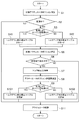
以下、上記第1〜第4の制御モード(図6A〜図6D)の中から代表して、第1の制御モード(パワーオンシフトアップ制御)の具体的な動作例を説明する。図7は、第1の制御モードの動作例を表すフローチャートである。 Hereinafter, as a representative example of the first to fourth control modes (FIGS. 6A to 6D), a specific operation example of the first control mode (power-on shift-up control) will be described. FIG. 7 is a flowchart illustrating an operation example of the first control mode.
S201において、制御装置10は、変速制御が第1の制御モード(パワーオンシフトアップ制御)であるか否かを判定する。第1の制御モードではない場合(S201:NO)、制御装置10は処理を終了する。
In S201, the
S202において、制御装置10は、ドグ係合指令を出力して、ドグ係合フェーズを実行する(上記図6Aのt1)。ドグ係合指令は、次クラッチCnを係合状態から解放状態に変化させる指令と、次変速機構Tnの可動ギアGn1を固定ギアGn2に向けて移動させる指令と、を含んでいる。また、ドグ係合指令は、前クラッチCpを係合状態から半係合状態に変化させる指令を含んでいる。具体的には、前クラッチCpの目標トルク容量は、これを一次減速比で除した値が目標エンジントルクと同じになるように設定される。
In S202, the
S203において、制御装置10は、ドグ係合フェーズが完了したか否かを判定する。判定方法としては、次の方法が考えられる。例えば、ギア位置センサ19bからの信号に基づき、シフトカム39bの位置がドグ係合に対応する範囲内にあるときに、ドグ係合フェーズの完了が判定される。また、入力軸32の回転速度を検出するセンサが設けられる場合には、エンジン回転速度を一次減速比で除した値と入力軸回転速度との差がドグ係合に対応する範囲内にあるときに、ドグ係合フェーズの完了が判定されてもよい。
In S203, the
S204において、制御装置10は、トルクフェーズを実行する(上記図6Aのt2)。トルクフェーズの開始時には、制御装置10は、前クラッチCpを解放状態に変化させる指令と、次クラッチCnを半係合状態に変化させる指令と、が出力される。具体的には、次クラッチCnの目標トルク容量は、これを一次減速比で除した値が目標エンジントルクと同じになるように設定される。
In S204, the
S205において、制御装置10は、トルクフェーズが完了したか否かを判定する。具体的にはクラッチセンサ19c,19dからの信号に基づいて、クラッチ40A,40Bの伝達トルク容量が目標トルク容量に到達したか否かが判定される。
In S205, the
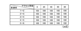
S206において、制御装置10は、イナーシャトルクを算出する。イナーシャトルクは、イナーシャフェーズにおいて適用される目標エンジントルクである(上記図6AのTe)。イナーシャトルクは、例えば、(現在エンジン回転速度−変速後到達エンジン回転速度)/イナーシャフェーズ発生時間×クランク周りイナーシャの式により求められる。イナーシャフェーズ発生時間は、例えば、図8に示されるようなイナーシャフェーズ発生時間が変速段とアクセル開度とに対応付けられたテーブルから読み出される。また、クランク周りイナーシャは、クランクシャフト21の軸回りに存在する重量物によるイナーシャであり、エンジン20の設計段階などにおいて予め求めることができる。
In S206, the
S207において、制御装置10は、イナーシャフェーズを実行し、エンジン回転速度Seが低下させる(上記図6Aのt3)。イナーシャフェーズが開始されると、目標エンジントルクは上記S206で算出されたイナーシャトルクに設定される。また、前クラッチCpの目標伝達トルクは最小値(例えば0Nm)に設定される。また、次クラッチCnの目標伝達トルクは、アクセル開度から決まる目標エンジントルクに1次減速比を乗じ、さらにオフセットトルクを加算した値に設定される。ここで、オフセットトルクは、次クラッチCnの目標伝達トルクが実際の伝達トルク容量Tcnと異なるためにイナーシャフェーズが進行しないような状況を解消するための値で、例えばS207が開始されてからの経過時間に応じて定まる値とされる。
In S207, the
S208において、制御装置10は、イナーシャフェーズが完了したか否かを判定する。例えば、|ドライブ軸回転速度×変速後ギア比×1次減速比−エンジン回転速度|< 閾値 の式が成立したときに、イナーシャフェーズの完了が判定される。また、例えば、(ドライブ軸回転速度×変速前ギア比×1次減速比−エンジン回転速度)/(ドライブ軸回転速度×(変速前ギア比−変速後ギア比)×1次減速比)> 閾値 の式が成立したときに、イナーシャフェーズの完了が判定されてもよい。また、例えば、上記2つの式の一方または両方が成立したときに、イナーシャフェーズの完了が判定されてもよい。
In S208, the
S209において、制御装置10は、目標エンジントルクを、アクセル開度から求まる通常の値に戻す。
In S209, the
S210において、制御装置10は、ドグ解放指令を出力して、ドグ解放フェーズを実行する(上記図6Aのt4)。ドグ解放指令は、前変速機構Tpの可動ギアGn1を中立位置に移動させる指令を含んでいる。
In S210, the
S211において、制御装置10は、ドグ解放フェーズが完了したか否かを判定する。判定方法としては、次の方法が考えられる。例えば、ギア位置センサ19bからの信号に基づき、シフトカム39bの位置がドグ解放に対応する範囲内にあるときに、ドグ解放フェーズの完了が判定される。また、入力軸32の回転速度を検出するセンサが設けられる場合には、エンジン回転速度を一次減速比で除した値と入力軸回転速度との差がドグ解放に対応する範囲内にあるときに、ドグ解放フェーズの完了が判定されてもよい。
In S211, the
S212において、制御装置10は、前クラッチCp及び次クラッチCnを係合状態に変化させる指令を出力する。以上により、第1の制御モード(パワーオンシフトアップ制御)に係る変速制御が終了する。
In S212, the
ところで、クラッチ40A,40Bでは、プレートの摩耗等の要因によって、クラッチアクチュエータ49A,49Bに与える指示値と、第1クラッチ40A及び第2クラッチ40Bに生じる伝達トルク容量との関係が経時的に変化することがある。そこで、以下に説明するように、制御装置10は、イナーシャフェーズの結果に基づいて、クラッチアクチュエータ49A,49Bに与える指示値と、第1クラッチ40A及び第2クラッチ40Bに生じる伝達トルク容量との関係を学習する。
Incidentally, in the
図9は、制御装置10の機能構成例を表すブロック図である。同図では、制御装置10が実現する機能のうち、目標アクチュエータポジションを決定する機能に係る部分と、目標アクチュエータポジションと実際に生じる伝達トルク容量との関係を学習する機能に係る部分と、を主に示している。制御装置10は、テーブル保持部51と、目標アクチュエータポジション決定部53と、変速条件判定部55と、アクチュエータ制御部57と、補正テーブル更新部59と、を備えている。目標アクチュエータポジション決定部53は、基礎値演算部53aと、補正値演算部53bと、を含んでいる。制御装置10に含まれる各部は、制御装置10のCPUがメモリに格納されたプログラムを実行することで実現される。
FIG. 9 is a block diagram illustrating a functional configuration example of the
テーブル保持部51は、基礎テーブル51aと、複数の補正テーブル51bと、を保持している。基礎テーブル51aには、クラッチ40A,40Bに生じさせる伝達トルク容量(目標トルク容量)と、そのためにクラッチアクチュエータ49A,49Bに与える目標アクチュエータポジション電圧の基礎値と、が記述されている。図10は、基礎テーブル51aの内容例を示す図である。
The
他方、補正テーブル51bには、基礎テーブル51aに記述された基礎値を補正するための補正値が記述されている。この補正値は、補正テーブル更新部59によりイナーシャフェーズの結果に基づいて更新される。基礎テーブル51aに記述された基礎値と、補正テーブル51bに記述された補正値と、が加算された値が目標アクチュエータポジション電圧とされる。これにより、クラッチ40A,40Bに実際に生じる伝達トルク容量が目標トルク容量に近づく。具体的には、補正テーブル51bには、目標トルク容量と、目標アクチュエータポジション電圧の補正値と、が記述されている。図11は、補正テーブル51bの内容例を示す図である。
On the other hand, correction values for correcting the basic values described in the basic table 51a are described in the correction table 51b. This correction value is updated by the correction
補正テーブル更新部59には、複数の補正テーブル51bが保持されている。これは、自動二輪車1の運転条件に依ってはイナーシャフェーズの結果が異なることがあり、その結果、目標アクチュエータポジション電圧の補正値の学習精度が高くなくなるおそれがあるためである。
The correction
例えば、エンジントルクが上昇中の場合と下降中の場合とでは、クラッチ40A,40Bに生じる伝達トルク容量が同じであっても、エンジン回転速度の変化特性が異なることがある。すなわち、エンジントルクの上昇はスロットル制御により実現されるため、エンジン回転速度の応答が比較的遅いのに対し、エンジントルクの下降は点火遅角制御により実現されるため、エンジン回転速度の応答が比較的速い。このため、エンジントルクが上昇中の場合と下降中の場合とでは、イナーシャフェーズ中のエンジン回転速度の変化率が異なって、その結果、イナーシャフェーズの結果に基づいて算出される目標アクチュエータポジション電圧の補正値も異なる可能性がある。
For example, when the engine torque is increasing and when the engine torque is decreasing, even if the transmission torque capacity generated in the
また、クラッチ40A,40Bの伝達トルク容量がヒステリシスを持つ場合などには、クラッチアクチュエータ49A,49Bに与えられる指示値が同じであっても、クラッチ40A,40Bに実際に生じる伝達トルク容量が異なることがある。従って、変速制御中におけるクラッチ40A,40Bの動かし方が異なると、イナーシャフェーズの結果に基づいて算出される目標アクチュエータポジション電圧の補正値も異なる可能性がある。
Further, when the transmission torque capacity of the
そこで、本実施形態では、イナーシャフェーズの結果が異なる可能性のある複数の運転条件のそれぞれに対応する補正テーブル51bを用意して、目標アクチュエータポジション電圧の補正値を利用及び更新する補正テーブル51bを運転条件ごとに換えている。以下、制御装置10の動作例について説明する。
Therefore, in the present embodiment, a correction table 51b corresponding to each of a plurality of operating conditions that may have different inertia phase results is prepared, and a correction table 51b that uses and updates the correction value of the target actuator position voltage is prepared. It is changed for each operating condition. Hereinafter, an operation example of the
[第1の動作例]
図12は、制御装置10の第1の動作例を表すフローチャートである。当該フローチャートが示す処理は、所定時間毎に実行される。本動作例において、テーブル保持部51には、エンジントルクが上昇中の条件で適用される補正テーブル51bと、エンジントルクが下降中の条件で適用される補正テーブル51bと、が保持されている。なお、本動作例において、エンジントルクが上昇中の条件が上記第1の制御モードに対応し、エンジントルクが下降中の条件が上記第4の制御モードに対応する。
[First operation example]
FIG. 12 is a flowchart illustrating a first operation example of the
S1において、目標アクチュエータポジション決定部53の基礎値演算部53aは、目標アクチュエータポジション電圧の基礎値を演算する。具体的には、基礎値演算部53aは、目標トルク容量に対応する目標アクチュエータポジション電圧の基礎値を、補正テーブル更新部59に保持された基礎テーブル51aから読み出す。目標トルク容量は、制御装置10の制御状態に応じて決定される。例えば、変速制御中以外では、クラッチ40A,40Bは係合状態とされるので、目標トルク容量は最大値に設定される。これに対し、変速制御中では、上述したように目標トルク容量が各フェーズで変化する。
In S1, the basic
S2において、目標アクチュエータポジション決定部53は、変速中であるか否かを判定する。変速中である場合(S2:YES)、目標アクチュエータポジション決定部53は、読み出された基礎値を保持する。他方、変速中でない場合には(S2:NO)、目標アクチュエータポジション決定部53は、読み出された基礎値を目標アクチュエータポジション電圧としてアクチュエータ制御部57に出力する。S11において、アクチュエータ制御部57は、受付けた目標アクチュエータポジション電圧を用いてクラッチアクチュエータ49A,49Bを駆動する。
In S2, the target actuator
S3において、変速条件判定部55は、現在の変速がエンジン回転速度が上昇する変速であるか、下降する変速であるかを判定する。このステップでは、実質的に、エンジントルクが下降中であるか、上昇中であるかを判定している。すなわち、エンジン回転速度が上昇する変速(シフトダウン変速)の場合はエンジントルクが下降中であり、エンジン回転速度が下降する変速(シフトアップ変速)の場合はエンジントルクが上昇中である。エンジン回転速度が上昇する変速であるか、下降する変速であるかの判定は、例えば、シフトスイッチ19fから入力される指令がシフトダウン指令であるか、シフトアップ指令であるかによって判定される。また、ギア位置センサ19bからの入力によっても判定が可能である。例えば、変速前ギア比が変速後ギア比より小さいか否か、或いは変速前ギア比と変速後ギア比の商が1以下であるか否か等によっても判定が可能である。
In S <b> 3, the shift
エンジン回転速度が上昇する変速である場合(S3:YES)、すなわちエンジントルクが下降中である場合には、S41が実行される。S41において、目標アクチュエータポジション決定部53の補正値演算部53bは、エンジントルクが下降中の条件で適用される補正テーブル51bから、目標トルク容量に対応する目標アクチュエータポジション電圧の補正値を読み出す。
If the engine speed is increasing (S3: YES), that is, if the engine torque is decreasing, S41 is executed. In S41, the correction
同様に、エンジン回転速度が下降する変速である場合(S3:NO)、すなわちエンジントルクが上昇中である場合には、S42が実行される。S42において、目標アクチュエータポジション決定部53の補正値演算部53bは、エンジントルクが上昇中の条件で適用される補正テーブル51bから、目標トルク容量に対応する目標アクチュエータポジション電圧の補正値を読み出す。
Similarly, S42 is executed when the shift is such that the engine speed decreases (S3: NO), that is, when the engine torque is increasing. In S42, the correction
S5において、目標アクチュエータポジション決定部53は、目標アクチュエータポジション電圧を補正する。具体的には、目標アクチュエータポジション決定部53は、上記S1で読み出された基礎値と、S41又はS42で読み出された補正値と、を合算した値を目標アクチュエータポジション電圧としてアクチュエータ制御部57に出力する。
In S5, the target actuator
S6において、補正テーブル更新部59は、学習実行条件が成立したか否かを判定する。学習実行条件が成立するのは、イナーシャフェーズが終了したときである。すなわち、上記図7のS208で説明したイナーシャフェーズの終了条件が成立したときに、学習実行条件が成立する。その他、クラッチアクチュエータ49A,49Bが正常であるか、クラッチセンサ19c,19dが正常であるか等の条件が組み合わされてもよい。さらに、エンジントルクやアクセル開度、車速などの最大値と最小値との差分の絶対値が所定以下であるか、バックトルクリミッタ−が非動作であるか等の条件が組み合わされてもよい。
In S6, the correction
学習実行条件が成立した場合には(S6:YES)、S7が実行される。これに対し、学習実行条件が成立していない場合には(S6:NO)、S11が実行される。S11において、アクチュエータ制御部57は、目標アクチュエータポジション決定部53から受付けた目標アクチュエータポジション電圧を用いてクラッチアクチュエータ49A,49Bを駆動する。これにより、変速制御の各フェーズでは、S41又はS42で読み出された補正値によって補正された目標アクチュエータポジション電圧が利用される。
If the learning execution condition is satisfied (S6: YES), S7 is executed. On the other hand, when the learning execution condition is not satisfied (S6: NO), S11 is executed. In S <b> 11, the
S7において、補正テーブル更新部59は、イナーシャフェーズの結果に基づき、トルク修正量を算出する。イナーシャフェーズの結果とは、例えば、イナーシャフェーズ発生時間の実績値を指す。トルク修正量は、イナーシャフェーズ発生時間の実績値と目標値との比を利用して求められる。この比は、イナーシャフェーズにおいて実際に生じた伝達トルク容量と、伝達トルク容量の目標値(目標トルク容量)との関係を表している。トルク修正量は、例えば、イナーシャトルク×(1−イナーシャフェーズ発生時間目標値/イナーシャフェーズ発生時間実績値)の式で求められる。ここで、イナーシャトルクは、上記図7のS206において算出される値である。また、イナーシャフェーズ発生時間目標値は、上記図7のS206においてイナーシャトルクの算出に用いられたイナーシャフェーズ発生時間(図8を参照)である。イナーシャフェーズ発生時間実績値は、イナーシャフェーズに実際に要した時間である。すなわち、上記図7のS207においてイナーシャフェーズが開始されてから、S206において終了が判定されるまでに要する時間である。
In S7, the correction
S8において、補正テーブル更新部59は、S7で得られたトルク修正量に基づいて、補正テーブル51b内の目標アクチュエータポジション電圧の補正値の学習量を算出する。学習量の算出は、例えば次のように行われる。始めに、補正テーブル更新部59は、イナーシャトルクとトルク修正量とを加算した値に対応する目標アクチュエータポジション電圧の基礎値を基礎テーブル51aから読み出す。次いで、補正テーブル更新部59は、この基礎値と、上記S1で基礎テーブル51aから読み出した目標アクチュエータポジション電圧の基礎値との差分を算出する。その後、補正テーブル更新部59は、この差分に所定の重み係数を乗じ、これにより得られる値を学習量とする。
In S8, the correction
S9において、変速条件判定部55は、実行中の変速がエンジン回転速度が上昇する変速であるか、下降する変速であるかを判定する。このS9は、上記S3と同じである。
In S9, the shift
エンジン回転速度が上昇する変速である場合(S9:YES)、すなわちエンジントルクが下降中である場合には、S101が実行される。S101において、補正テーブル更新部59は、上記S8で算出された学習量を用いて、エンジントルクが下降中の条件で適用される補正テーブル51b内の補正値を更新する。具体的に、補正テーブル更新部59は、上記S41で読み出した補正値と上記S8で算出した学習量とを加算し、得られた加算値を、補正テーブル51b内の上記S41で読み出された補正値が記述されていた箇所に上書きする。また、補正テーブル更新部59は、目標アクチュエータポジション決定部53が保持している補正値も、当該加算値と置き換える。
If it is a shift that increases the engine rotation speed (S9: YES), that is, if the engine torque is decreasing, S101 is executed. In S101, the correction
同様に、エンジン回転速度が下降する変速である場合(S9:NO)、すなわちエンジントルクが上昇中である場合には、S102が実行される。S102において、補正テーブル更新部59は、上記S8で算出された学習量を用いて、エンジントルクが上昇中の条件で適用される補正テーブル51b内の補正値を更新する。具体的に、補正テーブル更新部59は、上記S42で読み出した補正値と上記S8で算出した修正値とを加算し、得られた加算値を、補正テーブル51b内の上記S42で読み出された補正値が記述されていた箇所に上書きする。また、補正テーブル更新部59は、目標アクチュエータポジション決定部53が保持している補正値も、当該加算値と置き換える。
Similarly, when the engine speed is a shift that decreases (S9: NO), that is, when the engine torque is increasing, S102 is executed. In S102, the correction
S11において、アクチュエータ制御部57は、目標アクチュエータポジション決定部53から受付けた目標アクチュエータポジション電圧を用いてクラッチアクチュエータ49A,49Bを駆動する。
In S <b> 11, the
以上により、第1の動作例が終了する。このように、目標アクチュエータポジション電圧の補正値を利用及び更新する補正テーブル51bを、エンジントルクが下降中の条件と上昇中の条件とで換えることで、補正値の学習精度を向上させることが可能である。 Thus, the first operation example ends. As described above, the correction value learning accuracy can be improved by changing the correction table 51b that uses and updates the correction value of the target actuator position voltage between the condition in which the engine torque is decreasing and the condition in which the engine torque is increasing. It is.
[第2の動作例]
図13は、制御装置10の第2の動作例を表すフローチャートである。以下、上記第1の動作例と重複するステップについては、同番号を付すことで詳細な説明を省略する。本動作例において、テーブル保持部51には、第1の制御モード(パワーオンシフトアップ制御)、第2の制御モード(パワーオンシフトダウン制御)、第3の制御モード(パワーオフシフトアップ制御)、第4の制御モード(パワーオフシフトダウン制御)のそれぞれで適用される4種類の補正テーブル51bが保持されている。
[Second operation example]
FIG. 13 is a flowchart illustrating a second operation example of the
第1〜第4の制御モードのうち、第1及び第2の制御モードはエンジントルクが上昇中の条件下で実行され、第3及び第4の制御モードはエンジントルクが下降中の条件下で実行される。また、上述したように、第1及び第4の制御モードではトルクフェーズとイナーシャフェーズとがこの順に実行され、第2及び第3の制御モードではイナーシャフェーズとトルクフェーズとがこの順に実行されており、クラッチ40A,40Bの動かし方が異なる。
Among the first to fourth control modes, the first and second control modes are executed under conditions where the engine torque is increasing, and the third and fourth control modes are performed under conditions where the engine torque is decreasing. Executed. As described above, the torque phase and the inertia phase are executed in this order in the first and fourth control modes, and the inertia phase and the torque phase are executed in this order in the second and third control modes. The movement of the
S31において、変速条件判定部55は、実行中の変速が第1の制御モード(パワーオンシフトアップ制御)であるか否かを判定する。第1の制御モードである場合には(S31:YES)、S43が実行される。S43において、目標アクチュエータポジション決定部53の補正値演算部53bは、第1の制御モードで適用される補正テーブル51bから目標トルク容量に対応する目標アクチュエータポジション電圧の補正値を読み出す。
In S31, the shift
S32において、変速条件判定部55は、実行中の変速が第2の制御モード(パワーオンシフトダウン制御)であるか否かを判定する。第2の制御モードである場合には(S32:YES)、S44が実行される。S44において、目標アクチュエータポジション決定部53の補正値演算部53bは、第2の制御モードで適用される補正テーブル51bから目標トルク容量に対応する目標アクチュエータポジション電圧の補正値を読み出す。
In S32, the shift
S33において、変速条件判定部55は、実行中の変速が第3の制御モード(パワーオフシフトアップ制御)であるか否かを判定する。第3の制御モードである場合には(S33:YES)、S45が実行される。S45において、目標アクチュエータポジション決定部53の補正値演算部53bは、第3の制御モードで適用される補正テーブル51bから目標トルク容量に対応する目標アクチュエータポジション電圧の補正値を読み出す。
In S33, the shift
実行中の変速が第1〜第3の制御モードの何れでもない場合(S31〜S33:NO)、すなわち第4の制御モード(パワーオフシフトダウン制御)である場合には、S46が実行される。S46において、目標アクチュエータポジション決定部53の補正値演算部53bは、第4の制御モードで適用される補正テーブル51bから目標トルク容量に対応する目標アクチュエータポジション電圧の補正値を読み出す。
If the shift being executed is not one of the first to third control modes (S31 to S33: NO), that is, if the shift is in the fourth control mode (power-off shift down control), S46 is executed. . In S46, the correction
S5において、目標アクチュエータポジション決定部53は、上記S1で読み出された基礎値と、S43〜S46の何れかで読み出された補正値と、を合算した値を目標アクチュエータポジション電圧としてアクチュエータ制御部57に出力する。
In S5, the target actuator
S91〜S93において、変速条件判定部55は、実行中の変速が第1〜第4の制御モードの何れであるかを判定する。これらS91〜S93は、上記S31〜S33と同じである。S103〜S106において、補正テーブル更新部59は、上記S8で算出された学習量を用いて、各々の制御モードで適用される補正テーブル51b内の補正値を更新する。
In S91 to S93, the shift
第2の動作例によると、目標アクチュエータポジション電圧の補正値を利用及び更新する補正テーブル51bを、第1〜第4の制御モードのそれぞれで換えることで、補正値の学習精度を向上させることが可能である。 According to the second operation example, the correction table 51b that uses and updates the correction value of the target actuator position voltage is changed in each of the first to fourth control modes, thereby improving the learning accuracy of the correction value. Is possible.
[第3の動作例]
図14は、制御装置10の第3の動作例を表すフローチャートである。以下、上記第1又は第2の動作例と重複するステップについては、同番号を付すことで詳細な説明を省略する。本動作例において、テーブル保持部51には、上記第2の動作例と同様に、第1〜第4の制御モードのそれぞれで適用される4種類の補正テーブル51bが保持されている。
[Third operation example]
FIG. 14 is a flowchart illustrating a third operation example of the
S34において、変速条件判定部55は、実行中の変速がアクセルを開いた状態(パワーオン)での変速であるか、アクセルを閉じた状態(パワーオフ)での変速であるかを判定する。次いで、S35又はS36において、変速条件判定部55は、実行中の変速がエンジン回転速度が上昇する変速であるか、下降する変速であるかを判定する。これらS34〜S36により、第1〜第4の何れの制御モードであるかが反転される。S94〜S96においても、変速条件判定部55は、S34〜S36と同様に、実行中の変速が第1〜第4の制御モードの何れであるかを判定する。
In S34, the shift
第3の動作例によると、上記第2の動作例と同様に、目標アクチュエータポジション電圧の補正値を利用及び更新する補正テーブル51bを、第1〜第4の制御モードのそれぞれで換えることで、補正値の学習精度を向上させることが可能である。 According to the third operation example, similarly to the second operation example, by changing the correction table 51b that uses and updates the correction value of the target actuator position voltage in each of the first to fourth control modes, It is possible to improve the learning accuracy of the correction value.
[第1の変形例]
以下、上記実施形態の第1の変形例について説明する。図15は、第1の変形例を表すフローチャートである。以下、上記第1の動作例と重複するステップについては、同番号を付すことで詳細な説明を省略する。なお、同図では、上記図12のフローチャートに示されるS6〜S9,S101,S102のステップを省略している。
[First Modification]
Hereinafter, a first modification of the above embodiment will be described. FIG. 15 is a flowchart showing a first modification. Hereinafter, the same steps as those in the first operation example are denoted by the same reference numerals, and detailed description thereof is omitted. In the figure, steps S6 to S9, S101, and S102 shown in the flowchart of FIG. 12 are omitted.
S121〜S124において、変速条件判定部55は、変速制御に含まれるドグ係合フェーズ、トルクフェーズ、イナーシャフェーズ、ドグ解放フェーズの何れかが開始されたか否かを判定する。ドグ係合フェーズの開始は、例えば、変速制御が開始されたか、ドグ係合指令が出力されたか等によって判定される。ドグ解放フェーズの開始は、例えば、ドグ解放指令が出力されたか等によって判定される。
In S121 to S124, the shift
トルクフェーズの開始は、第1の制御モード(パワーオンシフトアップ制御)又は第4の制御モード(パワーオフシフトダウン制御)であれば、例えば、ドグの係合を検出したとき、前クラッチCpを解放状態に変化させる指令を検出したとき等に判定される。また、第2の制御モード(パワーオンシフトダウン制御)又は第3の制御モード(パワーオフシフトアップ制御)であれば、例えば、イナーシャフェーズにおいてエンジン回転速度が目標値に到達したとき、前クラッチCpを解放状態に変化させる指令を検出したとき等に判定される。 If the torque phase is started in the first control mode (power-on shift-up control) or the fourth control mode (power-off shift-down control), for example, when the engagement of the dog is detected, the front clutch Cp is This is determined when a command to change to the released state is detected. Further, in the second control mode (power-on shift-down control) or the third control mode (power-off shift-up control), for example, when the engine speed reaches a target value in the inertia phase, the front clutch Cp This is determined when a command to change the state to the released state is detected.
イナーシャフェーズの開始は、例えば、イナーシャトルクが設定されたか等によって判定される。また、第1の制御モード(パワーオンシフトアップ制御)又は第4の制御モード(パワーオフシフトダウン制御)であれば、例えば、前クラッチCpが解放状態に到達したとき等に判定される。また、第2の制御モード(パワーオンシフトダウン制御)又は第3の制御モード(パワーオフシフトアップ制御)であれば、例えば、ドグの係合を検出したとき等に判定される。 The start of the inertia phase is determined, for example, based on whether inertia torque is set. Further, in the first control mode (power-on shift-up control) or the fourth control mode (power-off shift-down control), for example, the determination is made when the front clutch Cp reaches a released state. Further, in the second control mode (power-on shift-down control) or the third control mode (power-off shift-up control), for example, determination is made when dog engagement is detected.
ドグ係合フェーズ、トルクフェーズ、イナーシャフェーズ、ドグ解放フェーズの何れかの開始が判定された場合には(S121〜S124:YES)、S125を経由してS5が実行される。すなわち、目標アクチュエータポジション決定部53は、S41又はS42で読み出した補正値を用いて目標アクチュエータポジション電圧を補正する。
When the start of any of the dog engagement phase, torque phase, inertia phase, and dog release phase is determined (S121 to S124: YES), S5 is executed via S125. That is, the target actuator
これに対し、ドグ係合フェーズ、トルクフェーズ、イナーシャフェーズ、ドグ解放フェーズの何れかの開始が判定されない場合には(S121〜S124:NO)、S125を経由せずにS5が実行される。すなわち、目標アクチュエータポジション電圧は、S41又はS42で読み出した補正値を用いずに、それ以前に保持していた補正値を用いて目標アクチュエータポジション電圧を補正する。 On the other hand, when the start of any of the dog engagement phase, torque phase, inertia phase, and dog release phase is not determined (S121 to S124: NO), S5 is executed without going through S125. That is, the target actuator position voltage is corrected using the correction value held before without using the correction value read in S41 or S42.
以上の処理によれば、上記S1で読み出される目標アクチュエータポジション電圧の基礎値は、変速制御の期間中、目標トルク容量が更新される毎に更新される。他方、S41又はS42で読み出される目標アクチュエータポジション電圧の補正値は、ドグ係合フェーズ、トルクフェーズ、イナーシャフェーズ、ドグ解放フェーズの各々の開始時に更新される。そして、各フェーズが実行されている間、補正値は更新されることなく適用され続ける。これにより、補正テーブル51b内の補正値にばらつきがある場合でも、各フェーズが実行されている間に、クラッチ40A,40Bに生じるクラッチ容量が不連続的に変化することを抑制することが可能である。
According to the above processing, the basic value of the target actuator position voltage read in S1 is updated every time the target torque capacity is updated during the shift control period. On the other hand, the correction value of the target actuator position voltage read in S41 or S42 is updated at the start of each of the dog engagement phase, torque phase, inertia phase, and dog release phase. Then, while each phase is being executed, the correction value continues to be applied without being updated. As a result, even when the correction values in the correction table 51b vary, it is possible to prevent the clutch capacity generated in the
[第2の変形例]
以下、上記実施形態の第2の変形例について説明する。図16は、第2の変形例を表すフローチャートである。同図のフローチャートに示される処理は、上記図12〜図14のフローチャートのS7において実行される。本例において、テーブル保持部51には、目標値テーブルと変位量テーブルとが保持されている。
[Second Modification]
Hereinafter, a second modification of the embodiment will be described. FIG. 16 is a flowchart showing a second modification. The process shown in the flowchart of FIG. 12 is executed in S7 of the flowcharts of FIGS. In this example, the
目標値テーブルは、クラッチ40A,40Bに生じさせる伝達トルク容量(目標トルク容量)と、クラッチアクチュエータ49A,49Bに与える目標アクチュエータポジション電圧と、の関係を表す。図17Aは、目標値テーブルの内容例を示す図である。この目標値テーブルは、上記基礎テーブル51aと同じである。また、変位量テーブルは、目標トルク容量と、クラッチ40A,40Bに含まれるプレッシャープレート43(上記図2を参照)の変位量と、の関係を表す。図17Bは、変位量テーブルの内容例を示す図である。
The target value table represents the relationship between the transmission torque capacity (target torque capacity) generated in the
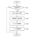
S131において、補正テーブル更新部59は、トルク修正量の演算指令が生じたか否かを判定する。これは、上記図12〜図14のフローチャートのS7に対応する。
In S131, the correction
S132において、補正テーブル更新部59は、イナーシャフェーズ期間中にクラッチ40A,40Bに生じた伝達トルク容量(以下、実クラッチ伝達トルクという。)を算出する。実クラッチ伝達トルクTcは、例えば、Tc=Te×1次減速比−J×dNe/dtの式で表されるTcのイナーシャフェーズ期間中の平均値として求められる。ここで、Teはイナーシャトルクを表し、Jはエンジン20のイナーシャを表し、Neはエンジン回転速度を表す。或いは、実クラッチ伝達トルクは、例えば、目標トルク容量−イナーシャトルク×イナーシャフェーズ発生時間目標値/イナーシャフェーズ発生時間目標値の式により求められてもよい。なお、目標トルク容量及びイナーシャトルクは、イナーシャフェーズの開始時の値とする。
In S132, the correction
S133において、補正テーブル更新部59は、図17Aに示される目標値テーブルから目標トルク容量に対応するアクチュエータポジション電圧(以下、目標電圧という。)を読み出す。この目標電圧は、図18Aに示されるグラフ中のYに対応する。また、補正テーブル更新部59は、図17Bに示される変位量テーブルから実クラッチ伝達トルクに対応するプレッシャープレート変位量(以下、実変位という。)を読み出す。この実変位は、図18Aに示されるグラフ中のXに対応する。図18A中の×印は、実変位と目標電圧を表す点である。この点の座標を(x1,y1)とする。また、図18A中の破線は、学習前のプレッシャープレート変位量とアクチュエータポジション電圧との関係を表す線である。本例では、アクチュエータポジション電圧とプレッシャープレート変位量とを線形かつ一意の関係として扱っている。
In S133, the correction
S134において、補正テーブル更新部59は、学習前の切片(0,b+β)と、目標電圧と実変位の点(x1,y1)とを通る直線の傾きを、傾き学習量Aとして算出する(図18Bを参照)。この直線は、図18B中の一点鎖線で表される。傾き学習量Aは((b+β−y1)/x1)/aの式で表される。ここで、aは傾きの設計値を表し、bは切片の設計値を表し、αは傾きの前回の補正値を表し、βは切片の前回の補正値を表す。
In S134, the correction
S135において、補正テーブル更新部59は、学習前の傾きα×aで、目標電圧と実変位の点(x1,y1)を通る直線の切片を、切片学習量Bとして算出する(図18Cを参照)。この直線は、図18C中の二点鎖線で表される。
In S135, the correction
S136において、補正テーブル更新部59は、傾きの補正値α及び切片の補正値βを更新する。更新は、例えば、算出された傾き学習量A及び切片学習量Bをそのまま傾きの補正値α及び切片の補正値βとしてもよいし、所定のフィルター値を用いてもよい。フィルター値を用いる方法では、例えば、傾きの補正値αiは、A×1/Wa+αi−1×(Wa−1)/Waの式で求められ、切片の補正値βiは、B×1/Wb+βi−1×(Wb−1)/Wbの式で求められる。フィルター値Wa,Wbを用いた場合の直線は、図18D中の実線で表される。なお、フィルター値Wa,Wbは、固定値であってもよいし、油温に応じて変化させてもよい。
In S136, the correction
以上のように、プレッシャープレート変位量とアクチュエータポジション電圧との関係を表す線の傾きの補正値α及び切片の補正値βを更新することで、実変位と目標電圧を表す一点(x1,y1)に基づいて全体を補正することが可能である。 As described above, one point (x1, y1) representing the actual displacement and the target voltage is updated by updating the correction value α of the slope of the line representing the relationship between the amount of displacement of the pressure plate and the actuator position voltage and the correction value β of the intercept. It is possible to correct the whole based on the above.
なお、本例では、アクチュエータポジション電圧とプレッシャープレート変位量との関係を用いたが、この態様に限られず、プレッシャープレート変位量に代えて、例えばクラッチ40A,40Bに動力を伝える油圧や荷重を用いてもよい。荷重としては、例えば、プル/プッシュロッドから生じる荷重であってもよいし、これに対する反力をとるクラッチカバーケースの歪みから求められる荷重であってもよい。
In this example, the relationship between the actuator position voltage and the pressure plate displacement amount is used. However, the present invention is not limited to this mode. For example, hydraulic pressure or a load that transmits power to the
また、本例に係る処理は、第1の制御モード(パワーオンシフトアップ制御)のみで適用されてもよい。パワーオフ系の第3及び第4の制御モードでは、エンジントルクが比較的小さい範囲で適用されるため、この範囲で得られる値を用いて全体を補正すると、エンジントルクが比較的大きい範囲でずれが生じる可能性があるためである。また、適用される頻度の低い第2の制御モードで全体を補正すると、適用される頻度の高い第1の制御モードとのずれが大きくなる可能性があるためである。 Further, the processing according to this example may be applied only in the first control mode (power-on shift-up control). In the third and fourth control modes of the power-off system, the engine torque is applied in a relatively small range. Therefore, if the entire value is corrected using a value obtained in this range, the engine torque is shifted in a relatively large range. This is because there is a possibility of occurrence. Moreover, if the whole is corrected in the second control mode that is applied less frequently, the deviation from the first control mode that is applied more frequently may increase.
また、本例に係る処理は領域毎に行われてもよい。図19は、領域毎の処理例を表すフローチャートである。S131〜S133は、上記図16のフローチャートと同様である。S138において、制御装置10はテーブル学習量を算出する。図20に示されるように、テーブル学習量Tblbasは、例えば、実変位x1−目標変位x0の式で表される。また、目標変位x0は、例えば、(y1−b−β)/(a×α)の式で表される。
Further, the processing according to this example may be performed for each region. FIG. 19 is a flowchart illustrating an example of processing for each region. S131 to S133 are the same as the flowchart of FIG. In S138, the
S139において、制御装置10は、目標変位x0を含む領域に対応する補正値を更新する。図21に示されるテーブルでは、プレッシャープレート変位量の領域ごとに補正値が対応付けられている。制御装置10は、目標変位x0を含む領域に対応する前回の補正値Tbli−1をテーブルから読み出し、読み出した前回の補正値Tbli−1と、S138で算出したテーブル学習量Tblbasとに基づいて補正値Tbliを求める。補正値Tbliは、例えば、Tbli=(Tblbas+Tbli−1)×1/Wtbl+Tbli−1×(Wtbl−1)/Wtblの式で求められる。Wtblはフィルター値を表す。
In S139, the
なお、テーブル学習値の更新は、目標変位x0を含む領域のみならず、その近傍の領域で併せて行ってもよい。補正値Tbliは、例えば、Tbli(K+n)=(Tblbas+Tbli−1(K+n))×1/Wtbl(n)+Tbli−1(K+n)×(Wtbl(n)−1)/Wtblの式で求められる。Kは、x0に対応する補正値のインデックスを表し、nは更新を行う範囲により決まる値である。 The table learning value may be updated not only in the area including the target displacement x0 but also in the vicinity of the area. The correction value Tbl i is, for example, an expression of Tbl i (K + n) = (Tblbas + Tbl i−1 (K + n)) × 1 / Wtbl (n) + Tbl i−1 (K + n) × (Wtbl (n) −1) / Wtbl Is required. K represents the index of the correction value corresponding to x0, and n is a value determined by the range to be updated.
また、テーブル学習値が所定値より大きいときには全ての領域で補正値を更新し、テーブル学習値が所定値より小さいときには一部の領域で補正値を更新してもよい。また、テーブル学習値に係数を乗じた値と、補正テーブル51bに保持された現在の補正値との差を、新たな補正値としてもよい。 Further, when the table learning value is larger than the predetermined value, the correction value may be updated in all areas, and when the table learning value is smaller than the predetermined value, the correction value may be updated in some areas. Further, a difference between a value obtained by multiplying the table learning value by a coefficient and the current correction value held in the correction table 51b may be set as a new correction value.
以上、本発明の実施形態について説明したが、本発明は上記実施形態に限定されるものではなく、種々の変形実施が当業者にとって可能であるのはもちろんである。 Although the embodiments of the present invention have been described above, the present invention is not limited to the above-described embodiments, and various modifications can be made by those skilled in the art.
上記実施形態では、基礎テーブル51a及び補正テーブル51bに目標トルク容量と目標アクチュエータポジション電圧との関係が記述されていたが、これに限られず、例えば目標トルク容量に代えて、目標トルク容量に対応する他の値を用いてもよい。目標トルク容量に対応する他の値としては、例えば、クラッチ40A,40Bに動力を伝える油圧や、プル/プッシュロッドが生じる荷重、プレッシャープレートの変位量などであってもよい。また、クラッチ40A,40Bのスレーブシリンダ変位量と、目標アクチュエータポジション電圧に対応するマスターシリンダ変位量との関係が記述されたテーブルが用いられてもよい。
In the above embodiment, the relationship between the target torque capacity and the target actuator position voltage is described in the basic table 51a and the correction table 51b. However, the present invention is not limited to this. For example, instead of the target torque capacity, it corresponds to the target torque capacity. Other values may be used. Other values corresponding to the target torque capacity may be, for example, a hydraulic pressure that transmits power to the
また、クラッチ40A,40Bが湿式クラッチである場合、テーブル保持部51に、油温に応じて適用される複数の補正テーブル51bが保持されてもよい。例えば、低油温時用の補正テーブル51bと、高油温時用の補正テーブル51bとが設けられる。低油温時と高油温時とでは、クラッチアクチュエータ49A,49Bに与えられる指示値が同じであっても、クラッチ40A,40Bに実際に生じる伝達トルク容量が異なることがある。そこで、目標アクチュエータポジション電圧の補正値を利用及び更新する補正テーブル51bを油温に応じて換えることで、変速ショックを抑制することが可能となる。
When the
また、図7のS207のイナーシャフェーズでは、例えば、目標のエンジン回転速度と実際のエンジン回転速度との差分に応じて伝達トルク容量を変化させるフィードバック制御を実行してもよい。この場合、図12のS7でのトルク修正量の演算は、次のように実行される。始めに、制御装置10は、イナーシャフェーズ終了時の実クラッチ伝達トルクを算出する。これは、上記図16のS132における実クラッチ伝達トルクの算出と同様である。次いで、制御装置10は、当該実クラッチ伝達トルクと、イナーシャフェーズ開始時の目標トルク容量との差または比を用いてトルク修正量を算出する。その後、制御装置10は、得られたトルク修正量に基づいて、補正テーブル51b内の目標アクチュエータポジション電圧の補正値の修正量を算出する。
Further, in the inertia phase of S207 in FIG. 7, for example, feedback control for changing the transmission torque capacity according to the difference between the target engine speed and the actual engine speed may be executed. In this case, the calculation of the torque correction amount in S7 of FIG. 12 is executed as follows. First, the
1 自動二輪車、2 前輪、1h,5i,3h,4h,6i,2h 固定ギア、5h,3i,4i,6h 可動ギア、10 制御装置、11 エンジンユニット、20 エンジン、21 クランクシャフト、30A 第1変速機構、30B 第2変速機構、31 入力軸、32 出力軸、39 シフトアクチュエータ、40A 第1クラッチ、40B 第2クラッチ、41 駆動部材、42 従動部材、49A,49B クラッチアクチュエータ、51 テーブル保持部、51a 基礎テーブル、51b 補正テーブル、53 目標アクチュエータポジション決定部、53a 基礎値演算部、53b 補正値演算部、55 変速条件判定部、57 アクチュエータ制御部、59 補正テーブル更新部、Cn 次クラッチ、Cp 前クラッチ、Gn1 可動ギア、Gn2 固定ギア、Gp1 可動ギア、Gp2 固定ギア、Tn 次変速機構、Tp 前変速機構、Se エンジン回転速度、Tcn 次クラッチの伝達トルク容量、Tcp 前クラッチの伝達トルク容量、Te エンジントルク。
1 motorcycle, 2 front wheels, 1h, 5i, 3h, 4h, 6i, 2h fixed gear, 5h, 3i, 4i, 6h movable gear, 10 control unit, 11 engine unit, 20 engine, 21 crankshaft, 30A first shift Mechanism, 30B second transmission mechanism, 31 input shaft, 32 output shaft, 39 shift actuator, 40A first clutch, 40B second clutch, 41 driving member, 42 driven member, 49A, 49B clutch actuator, 51 table holding portion, 51a Basic table, 51b correction table, 53 target actuator position determination unit, 53a basic value calculation unit, 53b correction value calculation unit, 55 shift condition determination unit, 57 actuator control unit, 59 correction table update unit, Cn next clutch, Cp previous clutch , Gn1 movable gear,
Claims (11)
変速期間中に、前記エンジンの出力トルクに対して前記クラッチのトルク容量が大きく又は小さくなるように前記アクチュエータに指示値を与えて、前記エンジンの回転速度を変化させる回転制御を実行する制御装置であって、
前記アクチュエータに同じ指示値が与えられても前記クラッチに生じるトルク容量が異なる複数の運転条件、又は、前記クラッチに同じトルク容量が生じても前記エンジンの回転速度の変化特性が異なる複数の運転条件の各々において適用される、前記トルク容量と前記アクチュエータの指示値との関係を表す条件別情報を保持する保持部と、
前記複数の運転条件の何れの運転条件で変速が行われるかを判定する判定部と、
前記判定された運転条件で適用される前記条件別情報に基づいて、前記トルク容量の目標値に対応する前記アクチュエータの指示値を決定する決定部と、
前記決定された指示値を前記アクチュエータに与えて、前記エンジンの回転速度を変化させる制御部と、
前記エンジンの回転速度を変化させた期間に生じた前記トルク容量の実績値と目標値との関係を表す情報に基づいて、前記判定された運転条件で適用される前記条件別情報を更新する更新部と、
を備えることを特徴とする制御装置。 Provided in a vehicle provided with a clutch whose torque capacity changes according to the operation of the actuator, and a dog clutch type transmission mechanism disposed downstream of the clutch in a path for transmitting torque output from the engine,
A control device for executing rotation control to change an engine rotation speed by giving an instruction value to the actuator so that a torque capacity of the clutch is increased or decreased with respect to an output torque of the engine during a shift period; There,
A plurality of operating conditions with different torque capacities generated in the clutch even when the same instruction value is given to the actuator, or a plurality of operating conditions with different change characteristics of the engine speed even when the same torque capacity is generated in the clutch A holding unit that holds information according to conditions representing a relationship between the torque capacity and the indicated value of the actuator,
A determination unit for determining which of the plurality of driving conditions is used to perform a shift;
A determination unit that determines an instruction value of the actuator corresponding to a target value of the torque capacity based on the condition-specific information applied under the determined operating condition;
A controller that applies the determined instruction value to the actuator to change a rotational speed of the engine;
Update to update the condition-specific information applied under the determined operating condition based on information representing the relationship between the actual value of the torque capacity and the target value generated during the period in which the rotation speed of the engine is changed And
A control device comprising:
請求項1に記載の制御装置。 The holding unit holds condition-specific information that is applied while the output torque of the engine is increasing and condition-specific information that is applied while the output torque of the engine is decreasing.
The control device according to claim 1.
変速期間中に、前記トルクを伝達する経路を一方のクラッチ及び変速機構から他方のクラッチ及び変速機構に切り替える切替制御と、前記エンジンの出力トルクに対して前記クラッチのトルク容量が大きく又は小さくなるように前記アクチュエータに指示値を与えて、前記エンジンの回転速度を変化させる回転制御と、を実行する制御装置であって、
前記エンジンの回転速度が上昇する変速であるか、下降する変速であるか、及び、前記切替制御が前記回転制御より先に実行される変速であるか、後に実行される変速であるか、によって定まる4つの運転条件の各々において適用される、前記トルク容量と前記アクチュエータの指示値との関係を表す条件別情報を保持する保持部と、
前記4つの運転条件の何れの運転条件で変速が行われるかを判定する判定部と、
前記判定された運転条件で適用される前記条件別情報に基づいて、前記トルク容量の目標値に対応する前記アクチュエータの指示値を決定する決定部と、
前記決定された指示値を前記アクチュエータに与えて、前記エンジンの回転速度を変化させる制御部と、
前記エンジンの回転速度を変化させた期間に生じた前記トルク容量の実績値と目標値との関係を表す情報に基づいて、前記判定された運転条件で適用される前記条件別情報を更新する更新部と、
を備えることを特徴とする制御装置。 Two clutches each having the torque input to a path for transmitting torque output from the engine, the torque capacity of which varies according to the operation of the actuator, and a common output shaft disposed downstream of each clutch A dog clutch type two speed change mechanism having
Switching control for switching the torque transmission path from one clutch and transmission mechanism to the other clutch and transmission mechanism during the shift period, and the torque capacity of the clutch to be larger or smaller than the output torque of the engine A control device that gives an instruction value to the actuator and performs rotation control to change a rotation speed of the engine,
Depending on whether the engine speed is a shift that increases or decreases, and whether the switching control is a shift that is performed before or after the rotation control. A holding unit that holds information classified by condition that represents a relationship between the torque capacity and the indicated value of the actuator, which is applied in each of four fixed operating conditions;
A determination unit that determines which of the four driving conditions is used to perform a shift;
A determination unit that determines an instruction value of the actuator corresponding to a target value of the torque capacity based on the condition-specific information applied under the determined operating condition;
A controller that applies the determined instruction value to the actuator to change a rotational speed of the engine;
Update to update the condition-specific information applied under the determined operating condition based on information representing the relationship between the actual value of the torque capacity and the target value generated during the period in which the rotation speed of the engine is changed And
A control device comprising:
請求項1または3に記載の制御装置。 The update unit calculates a correction amount of the indicated value of the actuator corresponding to the target value of the torque capacity based on a ratio between the actual value of the length of the period in which the rotation speed of the engine is changed and the target value. To
The control device according to claim 1 or 3.
請求項1または3に記載の制御装置。 The update unit calculates an actual value of the torque capacity generated during a period in which the rotation speed of the engine is changed, and based on a ratio between the actual value of the torque capacity and the target value, the target value of the torque capacity A correction amount of the indicated value of the actuator corresponding to
The control device according to claim 1 or 3.
前記トルク容量と前記アクチュエータの指示値の基礎値との関係が記述された基礎テーブルと、
前記各々の運転条件で適用される前記条件別情報としての、前記トルク容量と前記アクチュエータの指示値の補正値との関係が記述された複数の補正テーブルと、
を保持する、
請求項1または3に記載の制御装置。 The holding part is
A basic table describing the relationship between the torque capacity and the basic value of the indicated value of the actuator;
A plurality of correction tables describing the relationship between the torque capacity and the correction value of the indicated value of the actuator, as the condition-specific information applied in each of the operating conditions;
Hold,
The control device according to claim 1 or 3.
前記トルク容量の目標値に対応する前記アクチュエータの指示値の補正値は、前記回転制御の開始時に更新され、前記回転制御が実行されている期間中、適用され続ける、
請求項6に記載の制御装置。 The basic value of the indicated value of the actuator corresponding to the target value of the torque capacity is updated and applied every time the target value of the torque capacity is updated during the period in which the rotation control is being performed.
The correction value of the indicated value of the actuator corresponding to the target value of the torque capacity is updated at the start of the rotation control and continues to be applied during the period in which the rotation control is being executed.
The control device according to claim 6.
前記更新部は、
前記条件別情報に基づいて、前記トルク容量の目標値に対応する前記アクチュエータの指示値を算出し、
前記変位量情報に基づいて、前記トルク容量の実績値に対応する前記プレッシャープレートの変位量を表す値を算出し、
これらの値に基づいて、前記条件別情報及び前記変位量情報により定められる、前記アクチュエータの指示値と、前記プレッシャープレートの変位量を表す値との関数を補正し、
前記補正された関数に基づいて、前記条件別情報を更新する、
請求項1または3に記載の制御装置。 The holding unit holds displacement amount information representing a relationship between the torque capacity and a value representing a displacement amount of a pressure plate included in the clutch,
The update unit
Based on the condition-specific information, calculate an instruction value of the actuator corresponding to the target value of the torque capacity,
Based on the displacement amount information, a value representing the displacement amount of the pressure plate corresponding to the actual value of the torque capacity is calculated,
Based on these values, correct the function of the indicated value of the actuator and the value representing the displacement amount of the pressure plate, which is determined by the condition-specific information and the displacement amount information,
Updating the conditional information based on the corrected function;
The control device according to claim 1 or 3.
変速期間中に、前記エンジンの出力トルクに対して前記クラッチのトルク容量が大きく又は小さくなるように前記アクチュエータに指示値を与えて、前記エンジンの回転速度を変化させる回転制御を実行する制御装置であって、
前記アクチュエータに同じ指示値が与えられても前記クラッチに生じるトルク容量が異なる複数の運転条件、又は、前記クラッチに同じトルク容量が生じても前記エンジンの回転速度の変化特性が異なる複数の運転条件の各々において適用される、前記トルク容量と前記アクチュエータの指示値との関係を表す条件別情報を保持する保持部と、
前記複数の運転条件の何れの運転条件で変速が行われるかを判定する判定部と、
前記判定された運転条件で適用される前記条件別情報に基づいて、前記トルク容量の目標値に対応する前記アクチュエータの指示値を決定する決定部と、
前記決定された指示値を前記アクチュエータに与えて、前記エンジンの回転速度を変化させる制御部と、
を備えることを特徴とする制御装置。 Provided in a vehicle provided with a clutch whose torque capacity changes according to the operation of the actuator, and a dog clutch type transmission mechanism disposed downstream of the clutch in a path for transmitting torque output from the engine,
A control device for executing rotation control to change an engine rotation speed by giving an instruction value to the actuator so that a torque capacity of the clutch is increased or decreased with respect to an output torque of the engine during a shift period; There,
A plurality of operating conditions with different torque capacities generated in the clutch even when the same instruction value is given to the actuator, or a plurality of operating conditions with different change characteristics of the engine speed even when the same torque capacity is generated in the clutch A holding unit that holds information according to conditions representing a relationship between the torque capacity and the indicated value of the actuator,
A determination unit for determining which of the plurality of driving conditions is used to perform a shift;
A determination unit that determines an instruction value of the actuator corresponding to a target value of the torque capacity based on the condition-specific information applied under the determined operating condition;
A controller that applies the determined instruction value to the actuator to change a rotational speed of the engine;
A control device comprising:
Priority Applications (1)
| Application Number | Priority Date | Filing Date | Title |
|---|---|---|---|
| JP2011063195A JP5782278B2 (en) | 2011-03-22 | 2011-03-22 | Vehicle control device, vehicle and prime mover |
Applications Claiming Priority (1)
| Application Number | Priority Date | Filing Date | Title |
|---|---|---|---|
| JP2011063195A JP5782278B2 (en) | 2011-03-22 | 2011-03-22 | Vehicle control device, vehicle and prime mover |
Publications (2)
| Publication Number | Publication Date |
|---|---|
| JP2012197896A true JP2012197896A (en) | 2012-10-18 |
| JP5782278B2 JP5782278B2 (en) | 2015-09-24 |
Family
ID=47180328
Family Applications (1)
| Application Number | Title | Priority Date | Filing Date |
|---|---|---|---|
| JP2011063195A Active JP5782278B2 (en) | 2011-03-22 | 2011-03-22 | Vehicle control device, vehicle and prime mover |
Country Status (1)
| Country | Link |
|---|---|
| JP (1) | JP5782278B2 (en) |
Cited By (3)
| Publication number | Priority date | Publication date | Assignee | Title |
|---|---|---|---|---|
| WO2014112203A1 (en) * | 2013-01-17 | 2014-07-24 | 日産自動車株式会社 | Starting clutch control device for automatic transmission |
| KR20160068307A (en) * | 2014-12-05 | 2016-06-15 | 현대오트론 주식회사 | Method for studying slip factor of a dual clutch transmission |
| WO2023113032A1 (en) * | 2021-12-17 | 2023-06-22 | ヤマハ発動機株式会社 | Dog clutch-type transmission device |
Citations (4)
| Publication number | Priority date | Publication date | Assignee | Title |
|---|---|---|---|---|
| JPH0446225A (en) * | 1990-06-11 | 1992-02-17 | Zexel Corp | Correction of clutch operation control data |
| JPH10227355A (en) * | 1997-02-18 | 1998-08-25 | Nissan Motor Co Ltd | Speed change control device for automatic transmission |
| JP2004251456A (en) * | 2003-02-21 | 2004-09-09 | Borgwarner Inc | Method for controlling double clutch transmission |
| JP2011047511A (en) * | 2009-08-28 | 2011-03-10 | Yamaha Motor Co Ltd | Multiple clutch transmission control apparatus and multiple clutch transmission control method |
-
2011
- 2011-03-22 JP JP2011063195A patent/JP5782278B2/en active Active
Patent Citations (4)
| Publication number | Priority date | Publication date | Assignee | Title |
|---|---|---|---|---|
| JPH0446225A (en) * | 1990-06-11 | 1992-02-17 | Zexel Corp | Correction of clutch operation control data |
| JPH10227355A (en) * | 1997-02-18 | 1998-08-25 | Nissan Motor Co Ltd | Speed change control device for automatic transmission |
| JP2004251456A (en) * | 2003-02-21 | 2004-09-09 | Borgwarner Inc | Method for controlling double clutch transmission |
| JP2011047511A (en) * | 2009-08-28 | 2011-03-10 | Yamaha Motor Co Ltd | Multiple clutch transmission control apparatus and multiple clutch transmission control method |
Cited By (6)
| Publication number | Priority date | Publication date | Assignee | Title |
|---|---|---|---|---|
| WO2014112203A1 (en) * | 2013-01-17 | 2014-07-24 | 日産自動車株式会社 | Starting clutch control device for automatic transmission |
| CN104903623A (en) * | 2013-01-17 | 2015-09-09 | 日产自动车株式会社 | Starting clutch control device for automatic transmission |
| KR20160068307A (en) * | 2014-12-05 | 2016-06-15 | 현대오트론 주식회사 | Method for studying slip factor of a dual clutch transmission |
| KR101655286B1 (en) * | 2014-12-05 | 2016-09-07 | 현대오트론 주식회사 | Method for studying slip factor of a dual clutch transmission |
| US10252723B2 (en) | 2014-12-05 | 2019-04-09 | Hyundai Autron Co., Ltd. | Slip factor learning method of dual clutch transmission |
| WO2023113032A1 (en) * | 2021-12-17 | 2023-06-22 | ヤマハ発動機株式会社 | Dog clutch-type transmission device |
Also Published As
| Publication number | Publication date |
|---|---|
| JP5782278B2 (en) | 2015-09-24 |
Similar Documents
| Publication | Publication Date | Title |
|---|---|---|
| WO2014045357A1 (en) | Vehicle control device, vehicle, and engine | |
| JP5865651B2 (en) | Vehicle control device, vehicle and prime mover | |
| JP5762551B2 (en) | Vehicle control device, vehicle and prime mover | |
| JP5203401B2 (en) | Twin clutch transmission | |
| JP3946504B2 (en) | Vehicle control method, vehicle control device, transmission, and transmission control device | |
| JP5962780B2 (en) | Hybrid vehicle | |
| JP4972566B2 (en) | Control method and control apparatus for automatic transmission | |
| EP2657577B1 (en) | Vehicle control device and an automatic two-wheeled vehicle provided with same | |
| JP2007046659A (en) | Control device and method for vehicle | |
| JP5407979B2 (en) | Shift control device for automatic transmission | |
| JP5782278B2 (en) | Vehicle control device, vehicle and prime mover | |
| JP6380478B2 (en) | Control device for automatic transmission | |
| JP2001311464A (en) | Shift controller for synchromesh automatic transmission | |
| JPWO2012120937A1 (en) | Vehicle control device and motorcycle | |
| JP5873665B2 (en) | Dual clutch transmission for vehicle | |
| JP2002174335A (en) | Control device for automatic transmission and control method therefor | |
| JP5165035B2 (en) | Vehicle control apparatus and control method | |
| JP4986740B2 (en) | Shift control method for automobile | |
| WO2013125040A1 (en) | Vehicle control device | |
| JP2013036474A (en) | Power transmission control device | |
| JP6565813B2 (en) | Control device for automatic transmission | |
| JP2006214595A (en) | Method and device for controlling automobile, transmission, and method of controlling transmission | |
| JP5930122B2 (en) | Control device and control method for internal combustion engine for vehicle | |
| JP2013053726A (en) | Power transmission control device of vehicle | |
| JP2006037980A (en) | Automatic transmission control device, automatic transmission system and automatic transmission control method |
Legal Events
| Date | Code | Title | Description |
|---|---|---|---|
| A621 | Written request for application examination |
Free format text: JAPANESE INTERMEDIATE CODE: A621 Effective date: 20140228 |
|
| A977 | Report on retrieval |
Free format text: JAPANESE INTERMEDIATE CODE: A971007 Effective date: 20141218 |
|
| A131 | Notification of reasons for refusal |
Free format text: JAPANESE INTERMEDIATE CODE: A131 Effective date: 20150113 |
|
| A521 | Request for written amendment filed |
Free format text: JAPANESE INTERMEDIATE CODE: A523 Effective date: 20150303 |
|
| TRDD | Decision of grant or rejection written | ||
| A01 | Written decision to grant a patent or to grant a registration (utility model) |
Free format text: JAPANESE INTERMEDIATE CODE: A01 Effective date: 20150630 |
|
| A61 | First payment of annual fees (during grant procedure) |
Free format text: JAPANESE INTERMEDIATE CODE: A61 Effective date: 20150717 |
|
| R150 | Certificate of patent or registration of utility model |
Ref document number: 5782278 Country of ref document: JP Free format text: JAPANESE INTERMEDIATE CODE: R150 |
|
| R250 | Receipt of annual fees |
Free format text: JAPANESE INTERMEDIATE CODE: R250 |
|
| R250 | Receipt of annual fees |
Free format text: JAPANESE INTERMEDIATE CODE: R250 |
|
| R250 | Receipt of annual fees |
Free format text: JAPANESE INTERMEDIATE CODE: R250 |
|
| R250 | Receipt of annual fees |
Free format text: JAPANESE INTERMEDIATE CODE: R250 |
|
| R250 | Receipt of annual fees |
Free format text: JAPANESE INTERMEDIATE CODE: R250 |
|
| R250 | Receipt of annual fees |
Free format text: JAPANESE INTERMEDIATE CODE: R250 |