JP2012197732A - Pulsation damper and high-pressure pump having the same - Google Patents
Pulsation damper and high-pressure pump having the same Download PDFInfo
- Publication number
- JP2012197732A JP2012197732A JP2011062930A JP2011062930A JP2012197732A JP 2012197732 A JP2012197732 A JP 2012197732A JP 2011062930 A JP2011062930 A JP 2011062930A JP 2011062930 A JP2011062930 A JP 2011062930A JP 2012197732 A JP2012197732 A JP 2012197732A
- Authority
- JP
- Japan
- Prior art keywords
- movable part
- diaphragm
- fuel
- movable
- outer edge
- Prior art date
- Legal status (The legal status is an assumption and is not a legal conclusion. Google has not performed a legal analysis and makes no representation as to the accuracy of the status listed.)
- Granted
Links
- 230000010349 pulsation Effects 0.000 title claims abstract description 204
- 239000000446 fuel Substances 0.000 claims abstract description 254
- 238000007789 sealing Methods 0.000 claims description 19
- 238000013459 approach Methods 0.000 claims description 11
- 230000008961 swelling Effects 0.000 claims description 7
- 238000004891 communication Methods 0.000 claims description 6
- 230000000694 effects Effects 0.000 abstract description 27
- 238000002485 combustion reaction Methods 0.000 description 12
- 238000006073 displacement reaction Methods 0.000 description 10
- 239000003921 oil Substances 0.000 description 10
- 230000007423 decrease Effects 0.000 description 9
- 230000000052 comparative effect Effects 0.000 description 8
- 230000001629 suppression Effects 0.000 description 7
- 239000000463 material Substances 0.000 description 5
- 239000002184 metal Substances 0.000 description 5
- 238000000034 method Methods 0.000 description 5
- 230000001603 reducing effect Effects 0.000 description 4
- 229910001220 stainless steel Inorganic materials 0.000 description 4
- 239000010935 stainless steel Substances 0.000 description 4
- 239000002828 fuel tank Substances 0.000 description 3
- 239000000696 magnetic material Substances 0.000 description 3
- 239000004809 Teflon Substances 0.000 description 2
- 229920006362 Teflon® Polymers 0.000 description 2
- 238000013016 damping Methods 0.000 description 2
- 238000005192 partition Methods 0.000 description 2
- 230000002093 peripheral effect Effects 0.000 description 2
- 230000001105 regulatory effect Effects 0.000 description 2
- 239000011347 resin Substances 0.000 description 2
- 229920005989 resin Polymers 0.000 description 2
- 238000011144 upstream manufacturing Methods 0.000 description 2
- 238000005299 abrasion Methods 0.000 description 1
- 230000002238 attenuated effect Effects 0.000 description 1
- 230000001276 controlling effect Effects 0.000 description 1
- 230000003111 delayed effect Effects 0.000 description 1
- 238000010586 diagram Methods 0.000 description 1
- 239000012530 fluid Substances 0.000 description 1
- 230000004907 flux Effects 0.000 description 1
- 239000000295 fuel oil Substances 0.000 description 1
- 238000002347 injection Methods 0.000 description 1
- 239000007924 injection Substances 0.000 description 1
- 238000009434 installation Methods 0.000 description 1
- 239000000203 mixture Substances 0.000 description 1
- -1 outer diameter Substances 0.000 description 1
- 238000003466 welding Methods 0.000 description 1
Images


Abstract
Description
本発明は、燃料の圧力脈動を低減するパルセーションダンパ、およびこれを備えた高圧ポンプに関する。 The present invention relates to a pulsation damper that reduces fuel pressure pulsation, and a high-pressure pump including the pulsation damper.
近年、内燃機関に燃料を供給する燃料供給系統において、燃料タンクから低圧ポンプによって汲み上げられ、高圧ポンプへ供給される燃料圧力を可変制御する可変燃圧システムが採用される。この可変燃圧システムは、内燃機関の回転数又は負荷が通常運転時よりも低い場合、低圧ポンプから高圧ポンプに供給される燃料圧力を低くし、低圧ポンプの消費電力を低減している。一方、内燃機関の始動時などの場合、低圧ポンプから高圧ポンプに供給される燃料圧力を高め、燃料中のベーパによる始動不良のような不具合発生を防いでいる。
また、燃料供給系統では、燃料通路内に生じる燃圧脈動を低減するダンパ装置が設けられる。ダンパ装置には、2枚のダイアフラムから構成されたパルセーションダンパが設けられる。
特許文献1では、2枚のダイアフラムの間に燃料の流れる受圧室を設けている。2枚のダイアフラムは、受圧室の燃圧脈動により2枚のダイアフラムが互いに近づく動作と遠ざかる動作を繰り返し(以下、このダイアフラムの動作を「振幅動作」という)、その際の受圧室の容積変化によって受圧室の燃圧脈動を低減している。このダンパ装置には、2枚のダイアフラムの受圧室と反対側に2つのガス封入室が設けられている。ダンパ装置は、2つのガス封入室のガス封入圧を異なる値に設定することで、受圧室を流れる燃料の圧力変化に対応している。
特許文献2では、ダンパ装置の燃料室(特許文献2では「作業室66」)に2枚の金属ダイアフラムを収容している。このダンパ装置は、2枚の金属ダイアフラムの間に一定圧のガスを封入している。
特許文献3では、パルセーションダンパを構成する2枚のダイアフラムの間にプレートが設けられている。プレートはダイアフラムの径外方向へ延び、燃料室を形成するハウジングと蓋部材に挟まれている。
In recent years, a variable fuel pressure system that variably controls fuel pressure pumped from a fuel tank by a low-pressure pump and supplied to the high-pressure pump is employed in a fuel supply system that supplies fuel to an internal combustion engine. In this variable fuel pressure system, when the rotation speed or load of the internal combustion engine is lower than that during normal operation, the fuel pressure supplied from the low pressure pump to the high pressure pump is lowered, and the power consumption of the low pressure pump is reduced. On the other hand, when the internal combustion engine is started, the fuel pressure supplied from the low pressure pump to the high pressure pump is increased to prevent the occurrence of problems such as a start failure due to vapor in the fuel.
In the fuel supply system, a damper device that reduces fuel pressure pulsation generated in the fuel passage is provided. The damper device is provided with a pulsation damper composed of two diaphragms.
In Patent Document 1, a pressure receiving chamber through which fuel flows is provided between two diaphragms. The two diaphragms repeat the operation of moving the two diaphragms toward and away from each other by the fuel pressure pulsation of the pressure receiving chamber (hereinafter, the operation of the diaphragm is referred to as “amplitude operation”), and the pressure is received by the volume change of the pressure receiving chamber at that time. The fuel pressure pulsation of the chamber is reduced. In this damper device, two gas sealing chambers are provided on the side opposite to the pressure receiving chambers of the two diaphragms. The damper device responds to the pressure change of the fuel flowing through the pressure receiving chamber by setting the gas sealing pressures of the two gas sealing chambers to different values.
In
In
しかしながら、特許文献1では、受圧室の燃料圧力が2つのガス封入室の封入圧よりも低い場合、一方又は両方のダイアフラムの振幅動作が小さい、もしくは振幅動作しない。また、受圧室の燃料圧力が一方のガス封入室の封入圧と他方のガス封入室の封入圧との間にある場合、一方のダイアフラムの振幅動作は大きいが、他方のダイアフラムの振幅動作は小さい、もしくは振幅動作しない。このため、脈動抑制効果が低いことが懸念される。さらに、受圧室の燃料圧力が2つのガス封入室の封入圧よりも高い場合、両方のダイアフラムがガス封入室側に大きく変位し、ダイアフラムが早期に疲労破壊するおそれがある。
特許文献2では、2枚のダイアフラムの間のガス封入圧が一定圧であるので、燃料室の燃料圧力がガス封入圧よりも低い場合、両方のダイアフラムの振幅動作が小さい、もしくは振幅動作しない。また、燃料室の燃料圧力がガス封入圧よりも高い場合、2枚のダイアフラムが互いに近づく方向に変位し、2枚のダイアフラムの中心部の内側同士が接触するおそれがある。このとき、ダイアフラムに微小な傷が発生するおそれがある。そのため、その傷とダイアフラムの材質に含まれる金属介在物を起点に応力集中し、ダイアフラムは、その傷により疲労強度が低下し、早期に破損することが懸念される。
特許文献3では、2枚のダイアフラム同士が近づく方向に変位するときにダイアフラムとプレートとが接触することを避けるため、ダイアフラムとプレートとの距離を遠くすると、パルセーションダンパが大型化することが懸念される。
本発明は、上記問題に鑑みてなされたものであり、燃料室に供給される燃料圧力が大きく変化する環境下に対応し、高い脈動低減効果を得ることの可能なパルセーションダンパ及びそれを用いた高圧ポンプを提供することを目的とする。
However, in Patent Document 1, when the fuel pressure in the pressure receiving chamber is lower than the sealing pressures of the two gas sealing chambers, the amplitude operation of one or both diaphragms is small or does not operate. Further, when the fuel pressure in the pressure receiving chamber is between the sealing pressure in one gas sealing chamber and the sealing pressure in the other gas sealing chamber, the amplitude operation of one diaphragm is large, but the amplitude operation of the other diaphragm is small. Or the amplitude does not work. For this reason, we are anxious about the low pulsation suppression effect. Furthermore, when the fuel pressure in the pressure receiving chamber is higher than the sealing pressures of the two gas sealing chambers, both diaphragms are greatly displaced toward the gas sealing chamber, and there is a risk that the diaphragms will fatigue early.
In
In
The present invention has been made in view of the above problems, and is applicable to an environment in which the fuel pressure supplied to the fuel chamber changes greatly and can obtain a high pulsation reduction effect and uses the pulsation damper. The purpose is to provide a high-pressure pump.
上記課題を解決するため、請求項1に記載の発明によると、燃料供給系統の燃料が流れる燃料室に設けられ、燃料供給系統に生じる燃料の圧力脈動を低減するパルセーションダンパは、第1ダイアフラム、第2ダイアフラム、中間部材及び弾性部材を備える。
第1ダイアフラムは、燃料室の燃圧脈動により弾性変形可能な第1可動部、及びこの第1可動部の外縁に設けられる環状の第1外縁部を有する。
第2ダイアフラムは、第1可動部と共に所定圧のガスが封入される密閉空間を形成し燃料室の燃圧脈動により弾性変形可能な第2可動部、及びこの第2可動部の外縁に設けられる環状の第2外縁部を有する。
第1外縁部と第2外縁部との間に設けられる中間部材は、密閉空間へ延びる。
中間部材に設けられる弾性部材は、燃料室の燃料圧力により第1可動部と第2可動部とが互いに近づく方向に変位するとき、第1可動部及び第2可動部の少なくともいずれか一方と当接し、第1可動部と第2可動部と中間部材との接触を防ぐ。
In order to solve the above-described problem, according to the first aspect of the present invention, the pulsation damper provided in the fuel chamber through which the fuel of the fuel supply system flows to reduce the pressure pulsation of the fuel generated in the fuel supply system is provided with the first diaphragm. A second diaphragm, an intermediate member, and an elastic member.
The first diaphragm has a first movable part that can be elastically deformed by the fuel pressure pulsation of the fuel chamber, and an annular first outer edge part provided at the outer edge of the first movable part.
The second diaphragm forms a sealed space in which a gas of a predetermined pressure is sealed together with the first movable portion, and is elastically deformable by the fuel pressure pulsation of the fuel chamber, and an annular provided at the outer edge of the second movable portion. Having a second outer edge.
The intermediate member provided between the first outer edge portion and the second outer edge portion extends to the sealed space.
The elastic member provided in the intermediate member is in contact with at least one of the first movable portion and the second movable portion when the first movable portion and the second movable portion are displaced toward each other due to the fuel pressure in the fuel chamber. The first movable part, the second movable part, and the intermediate member are prevented from coming into contact with each other.
これにより、燃料室の燃料圧力が密閉空間のガス封入圧よりも高圧になるとき、第1可動部と弾性部材、及び第2可動部と弾性部材とが当接できる。このため、第1可動部と第2可動部と中間部材との接触を防ぐことができる。したがって、第1、第2ダイアフラムの疲労強度の低下を抑制し、パルセーションダンパの耐用期間を長くすることができる。
例えば、可変燃圧システムの低圧時における燃料室の燃料圧力に対応させて密閉空間のガス封入圧を設定した場合、低圧時及び通常圧時には、第1可動部と第2可動部との振幅動作による燃料室の容積変化によって燃圧脈動を低減することができる。また、弾性部材の弾性係数を小さくすれば、高圧時には、第1可動部と第2可動部と弾性部材とが共に振幅動作することで、燃料室の燃圧脈動を低減することができる。したがってパルセーションダンパは、燃料室に供給される燃料圧力差が大きく変化する環境下に対応しつつ、2枚のダイアフラムによって燃圧脈動を低減することが可能になり、高い脈動低減効果を得ることができる。
なお、燃料室は、燃料供給系統において、高圧ポンプと一体又は別体で設けることが可能である。また、燃料室は、高圧ポンプの加圧室の上流側又は下流側のどちらに設けられていてもよい。
Thereby, when the fuel pressure in the fuel chamber becomes higher than the gas filling pressure in the sealed space, the first movable portion and the elastic member, and the second movable portion and the elastic member can come into contact with each other. For this reason, contact with a 1st movable part, a 2nd movable part, and an intermediate member can be prevented. Therefore, it is possible to suppress a decrease in fatigue strength of the first and second diaphragms and to extend the useful life of the pulsation damper.
For example, when the gas filling pressure of the sealed space is set in correspondence with the fuel pressure of the fuel chamber at the time of low pressure of the variable fuel pressure system, at the time of low pressure and normal pressure, it depends on the amplitude operation of the first movable portion and the second movable portion. Fuel pressure pulsation can be reduced by changing the volume of the fuel chamber. Further, if the elastic coefficient of the elastic member is reduced, the fuel chamber pulsation can be reduced by the amplitude operation of the first movable portion, the second movable portion, and the elastic member at high pressure. Therefore, the pulsation damper can reduce the fuel pressure pulsation by the two diaphragms while dealing with an environment in which the difference in the fuel pressure supplied to the fuel chamber changes greatly, and can obtain a high pulsation reduction effect. it can.
The fuel chamber can be provided integrally or separately from the high-pressure pump in the fuel supply system. The fuel chamber may be provided on either the upstream side or the downstream side of the pressurizing chamber of the high-pressure pump.
請求項2に記載の発明によると、弾性部材は、第1可動部及び第2可動部の少なくともいずれか一方と当接するとき、当接した第1可動部又は第2可動部と共に振幅動作可能である。
これにより、燃料室の燃料圧力が密閉空間のガス封入圧よりも高いとき、第1可動部と第2可動部と弾性部材とが共に振幅動作し、燃料室の燃圧脈動を低減することができる。
According to the second aspect of the present invention, when the elastic member abuts on at least one of the first movable portion and the second movable portion, the elastic member can perform an amplitude operation together with the abutted first movable portion or the second movable portion. is there.
As a result, when the fuel pressure in the fuel chamber is higher than the gas filling pressure in the sealed space, the first movable portion, the second movable portion, and the elastic member operate together to reduce the fuel pressure pulsation in the fuel chamber. .
請求項3に記載の発明によると、弾性部材は、第1ダイアフラム及び第2ダイアフラムの中心軸上に設けられる。
一般に第1可動部及び第2可動部は、中心軸上に位置する個所の変位が最も大きい。したがって、第1可動部と第2可動部とが互いに近づく方向へ変位するとき、第1可動部と中間部材、第2可動部と中間部材との接触を弾性部材によって防ぐことができる。
According to the invention described in
In general, the first movable part and the second movable part have the largest displacement at a position located on the central axis. Therefore, when the first movable portion and the second movable portion are displaced in a direction approaching each other, contact between the first movable portion and the intermediate member, and the second movable portion and the intermediate member can be prevented by the elastic member.
請求項4に記載の発明によると、弾性部材は、中間部材と第1ダイアフラムとにより区画される第1の密閉空間と、中間部材と第2ダイアフラムとにより区画される第2の密閉空間とを連通する連通孔を有する。
これにより、第1の密閉空間と第2の密閉空間とのガス封入圧が略同じになる。このため、第1ダイアフラムの弾性係数と第2ダイアフラムの弾性係数とを略同じ値にすることができる。したがって、2枚のダイアフラムの燃圧脈動効果が合算されることで、パルセーションダンパは高い脈動低減効果を発揮することができる。
According to the invention described in claim 4, the elastic member includes a first sealed space defined by the intermediate member and the first diaphragm, and a second sealed space defined by the intermediate member and the second diaphragm. It has a communication hole that communicates.
Thereby, the gas filling pressures of the first sealed space and the second sealed space are substantially the same. For this reason, the elastic coefficient of a 1st diaphragm and the elastic coefficient of a 2nd diaphragm can be made into the substantially same value. Therefore, the fuel pressure pulsation effect of the two diaphragms is added together, so that the pulsation damper can exhibit a high pulsation reduction effect.
請求項5に記載の発明によると、弾性部材は、第1ダイアフラム及び第2ダイアフラムの軸を中心とした同心円上に複数個設けられる。
複数個の弾性部材により第1ダイアフラム及び第2ダイアフラムを支持することで、弾性部材が単数の場合と比較して、弾性部材の弾性係数を小さく形成することが可能になる。これにより、弾性部材と第1可動部と第2可動部とが共に振幅動作するときの脈動低減効果を高めることができる。
According to the invention described in
By supporting the first diaphragm and the second diaphragm by a plurality of elastic members, the elastic coefficient of the elastic member can be made smaller than in the case of a single elastic member. Thereby, the pulsation reduction effect when the elastic member, the first movable portion, and the second movable portion are all operated in amplitude can be enhanced.
請求項6に記載の発明によると、複数個の弾性部材は、中間部材側の外径よりも第1ダイアフラム側の外径が細く形成され、中間部材側の外径よりも第2ダイアフラム側の外径が細く形成される。
これにより、弾性部材の第1可動部側の端部及び第2可動部側の端部のばね定数を小さく設定することが可能になる。これにより、弾性部材と第1可動部と第2可動部とが共に振幅動作するときの脈動低減効果を高めることができる。
According to the invention described in
Thereby, it becomes possible to set small the spring constant of the edge part by the side of the 1st movable part and the edge part by the side of the 2nd movable part of an elastic member. Thereby, the pulsation reduction effect when the elastic member, the first movable portion, and the second movable portion are all operated in amplitude can be enhanced.
請求項7に記載の発明によると、複数個の弾性部材は、第1可動部側の端部が径内方向に曲折し、第2可動部側の端部が径内方向に曲折している。
これにより、弾性部材のばね定数を小さく設定することが可能になる。
According to the seventh aspect of the present invention, the plurality of elastic members have the end portion on the first movable portion side bent in the radially inward direction and the end portion on the second movable portion side bent in the radially inward direction. .
Thereby, the spring constant of the elastic member can be set small.
請求項8に記載の発明によると、複数の弾性部材の第1可動部側の端部は、燃料室の燃料圧力が密閉空間のガス封入圧よりも高圧になり第1可動部と第2可動部とが近づく方向に変位したときの第1可動部の内壁の形状に対応している。また、複数の弾性部材の第2可動部側の端部は、燃料室の燃料圧力が密閉空間のガス封入圧よりも高圧になり第1可動部と第2可動部とが近づく方向に変位したときの第2可動部の内壁の形状に対応している。
これにより、可変燃圧システムの高圧時、複数の弾性部材は、第1、第2可動部に略均等に弾性力を印加することができる。したがって、弾性部材と第1、第2可動部とが当接するときの第1、第2ダイアフラムに応力集中が生じることを低減することができる。また、第1可動部及び第2可動部の高い脈動減衰効果を得ることができる。
According to the eighth aspect of the present invention, the first movable portion and the second movable portion of the end portions of the plurality of elastic members on the first movable portion side are such that the fuel pressure in the fuel chamber is higher than the gas filling pressure in the sealed space. This corresponds to the shape of the inner wall of the first movable part when it is displaced in the direction in which the part approaches. Further, the end portions of the plurality of elastic members on the second movable portion side are displaced in a direction in which the fuel pressure in the fuel chamber becomes higher than the gas filling pressure in the sealed space and the first movable portion and the second movable portion approach each other. This corresponds to the shape of the inner wall of the second movable part.
Thereby, at the time of the high pressure of a variable fuel pressure system, a plurality of elastic members can apply elastic force to the 1st and 2nd movable parts substantially equally. Therefore, it is possible to reduce the occurrence of stress concentration in the first and second diaphragms when the elastic member and the first and second movable parts abut. Moreover, the high pulsation damping effect of the first movable part and the second movable part can be obtained.
請求項9に記載の発明によると、複数個の弾性部材は、第1ダイアフラム及び第2ダイアフラムの軸を中心とした環状に形成される。
可変燃圧システムの高圧時、複数の弾性部材は、第1、第2可動部に略均等に弾性力を印加することができる。
According to the ninth aspect of the present invention, the plurality of elastic members are formed in an annular shape around the axes of the first diaphragm and the second diaphragm.
When the variable fuel pressure system is at a high pressure, the plurality of elastic members can apply the elastic force to the first and second movable parts substantially evenly.
請求項10に記載の発明によると、弾性部材は、第1可動部側の端部及び第2可動部側の端部が曲面である。
これにより、第1可動部又は第2可動部と弾性部材とが当接したときの衝撃が低減され、第1、第2ダイアフラムに応力集中が生じることを抑制することができる。
According to the invention described in
Thereby, the impact when the 1st movable part or the 2nd movable part and an elastic member contact is reduced, and it can control that stress concentration arises in the 1st and 2nd diaphragm.
請求項11に記載の発明によると、弾性部材は、第1支持部及び第2支持部を有する。
第1支持部は、中間部材の第1ダイアフラム側に環状に設けられ、第1可動部側の端面が径外方向から径内方向へ向けて第2可動部側へ傾斜しており、第1可動部と第2可動部とが互いに近づく方向へ変位したとき、第1可動部の外縁を支持する。
第2支持部は、中間部材の第2ダイアフラム側に環状に設けられ、第2可動部側の端面が径外方向から径内方向へ向けて第1可動部側へ傾斜しており、第1可動部と第2可動部とが互いに近づく方向へ変位したとき、第2可動部の外縁を支持する。
これにより、第1可動部と第2可動部とが互いに近づく方向へ変位したとき、第1可動部と第2可動部とが接触することを防ぐことができる。
また、第1支持部と第2支持部は、それぞれ第1可動部と第2可動部の外縁を支持する。このため、第1可動部と第2可動部は、その外縁よりも径内側の中央部が振幅動作することで、脈動抑制効果を発揮することができる。
According to the invention described in
The first support portion is annularly provided on the first diaphragm side of the intermediate member, and the end surface on the first movable portion side is inclined from the radially outer direction toward the radially inner direction toward the second movable portion side, When the movable part and the second movable part are displaced in a direction approaching each other, the outer edge of the first movable part is supported.
The second support portion is provided in an annular shape on the second diaphragm side of the intermediate member, and the end surface on the second movable portion side is inclined from the radially outward direction toward the radially inward direction toward the first movable portion side. When the movable part and the second movable part are displaced toward each other, the outer edge of the second movable part is supported.
Thereby, when a 1st movable part and a 2nd movable part displace to the direction which mutually approaches, it can prevent that a 1st movable part and a 2nd movable part contact.
The first support portion and the second support portion support the outer edges of the first movable portion and the second movable portion, respectively. For this reason, the 1st movable part and the 2nd movable part can exhibit a pulsation suppression effect because the central part inside the diameter of the outer edge performs an amplitude operation.
請求項12に記載の発明によると、弾性部材は、第1接続部、第1挟持部、第2接続部及び第2挟持部を有する。
第1接続部は、第1支持部から第1外縁部側に延びる。
第1挟持部は、第1接続部から第1外縁部と第2外縁部との間に延びる。
第2接続部は、第2支持部から第2外縁部側に延びる。
第2挟持部は、第2接続部から第1外縁部と第2外縁部との間に延びる。
これにより、第1外縁部、第1挟持部、中間部材、第2挟持部及び第2外縁部を板厚方向から1回の溶接行程、又は径方向から1回または2回の溶接行程で容易に接続することができる。
According to invention of
The first connection portion extends from the first support portion to the first outer edge portion side.
The first sandwiching portion extends between the first outer edge portion and the second outer edge portion from the first connection portion.
The second connection portion extends from the second support portion to the second outer edge portion side.
The second clamping part extends from the second connection part between the first outer edge part and the second outer edge part.
Accordingly, the first outer edge portion, the first holding portion, the intermediate member, the second holding portion, and the second outer edge portion can be easily welded once from the plate thickness direction, or once or twice from the radial direction. Can be connected to.
請求項13に記載の発明によると、パルセーションダンパは中間部材を備えていない。弾性部材は第1挟持部及び第2挟持部によって密閉空間に取り付けられる。
これにより、中間部材の板厚相当分、第1可動部と第2可動部との距離を近くすることで、パルセーションダンパの軸方向の体格を小さくすることができる。
According to invention of
Thereby, the physique of the pulsation damper in the axial direction can be reduced by reducing the distance between the first movable part and the second movable part by an amount corresponding to the plate thickness of the intermediate member.
請求項14に記載の発明によると、パルセーションダンパは、第1カバー部材及び第2カバー部材を備える。
第1カバー部材は、第1外縁部の第2外縁部と反対側に設けられる環状の第1環状部、及びこの第1環状部から第1可動部の第2可動部と反対側へ延び、第1可動部の第2可動部と反対側への膨らみを規制する第1規制部を有する。
第2カバー部材は、第2外縁部の第1外縁部と反対側に設けられる環状の第2環状部、及びこの第2環状部から第2可動部の第1可動部と反対側へ延び、第2可動部の第1可動部と反対側への膨らみを規制する第2規制部を有する。
これにより、高圧ポンプの作動時と非作動時との燃料室の燃圧の変動による第1可動部と第2可動部との変位を小さくすることが可能になる。したがって、その際の応力振幅が小さくなるので、パルセーションダンパの耐用期間を長くすることができる。
According to the invention described in
The first cover member extends from the first annular portion to the opposite side to the second movable portion of the first movable portion, and the annular first annular portion provided on the opposite side of the first outer edge portion from the second outer edge portion. It has a 1st control part which controls the swelling to the opposite side to the 2nd movable part of the 1st movable part.
The second cover member has an annular second annular portion provided on the opposite side of the second outer edge portion from the first outer edge portion, and extends from the second annular portion to the opposite side of the first movable portion of the second movable portion, It has a 2nd control part which controls the swelling to the opposite side to the 1st movable part of the 2nd movable part.
Thereby, it becomes possible to reduce the displacement of the first movable part and the second movable part due to the fluctuation of the fuel pressure in the fuel chamber when the high-pressure pump is activated and when it is not activated. Therefore, since the stress amplitude at that time is reduced, the service life of the pulsation damper can be extended.
請求項15に記載の発明によると、パルセーションダンパは、弾性部材を有していない。
第1ダイアフラムと第2ダイアフラムとの間に設けられる板状の中間部材は、第1ダイアフラム側に第1の密閉空間を区画し、第2ダイアフラム側に第2の密閉空間を区画すると共に、第1ダイアフラム及び第2ダイアフラムの軸中心で第1の密閉空間と第2の密閉空間とを連通し、第1可動部と第2可動部との接触を防ぐ孔を有する。
これにより、第1可動部と第2可動部とが近づいた場合、中間部材の板厚の分、第1可動部と第2可動部との接触を防ぐことができる。
また、第1の密閉空間と第2の密閉空間とのガスの封入圧が略同じになる。このため、第1ダイアフラムの弾性係数と第2ダイアフラムの弾性係数とを略同じ値にすることができる。したがって、2枚のダイアフラムの燃圧脈動効果が合算されることで、パルセーションダンパは高い脈動低減効果を発揮することができる。
なお、燃料室は、燃料供給系統において、高圧ポンプと一体又は別体で設けることが可能である。また、燃料室は、高圧ポンプの加圧室の上流側又は下流側のどちらに設けられていてもよい。
According to the invention described in
The plate-shaped intermediate member provided between the first diaphragm and the second diaphragm partitions the first sealed space on the first diaphragm side, partitions the second sealed space on the second diaphragm side, and The first sealed space and the second sealed space communicate with each other at the axial centers of the first diaphragm and the second diaphragm, and have a hole that prevents contact between the first movable part and the second movable part.
Thereby, when the 1st movable part and the 2nd movable part approach, contact with the 1st movable part and the 2nd movable part can be prevented for the thickness of the intermediate member.
Further, the gas sealing pressures in the first sealed space and the second sealed space are substantially the same. For this reason, the elastic coefficient of a 1st diaphragm and the elastic coefficient of a 2nd diaphragm can be made into the substantially same value. Therefore, the fuel pressure pulsation effect of the two diaphragms is added together, so that the pulsation damper can exhibit a high pulsation reduction effect.
The fuel chamber can be provided integrally or separately from the high-pressure pump in the fuel supply system. The fuel chamber may be provided on either the upstream side or the downstream side of the pressurizing chamber of the high-pressure pump.
請求項16に記載の発明によると、高圧ポンプは、プランジャと、そのプランジャの往復移動によって燃料が加圧される加圧室、及びこの加圧室と連通する燃料室を有するハウジングと、加圧室から燃料室に排出される燃料の圧力脈動を低減可能な請求項1〜15のいずれか一項に記載のパルセーションダンパと、を備える。 According to the sixteenth aspect of the present invention, the high-pressure pump includes a plunger, a pressurizing chamber in which fuel is pressurized by the reciprocating movement of the plunger, a housing having a fuel chamber communicating with the pressurizing chamber, The pulsation damper as described in any one of Claims 1-15 which can reduce the pressure pulsation of the fuel discharged | emitted from a chamber to a fuel chamber.
以下、本発明の複数の実施形態を図面に基づいて説明する。
(第1実施形態)
本発明の第1実施形態によるパルセーションダンパを用いた内燃機関の燃料供給系統を図3に示す。燃料供給系統1は、燃料タンク2、低圧ポンプ3、高圧ポンプ10、デリバリパイプ4及びダンパ装置5等を備えている。
燃料供給系統では、燃料タンク2の燃料が低圧ポンプ3によって汲み上げられ、低圧燃料配管101を通り、高圧ポンプ10へ供給される。本実施形態の燃料供給系統1では、高圧ポンプ10へ供給される燃料圧力を可変制御する可変燃圧システムが採用される。この可変燃圧システムは、内燃機関の回転数又は負荷が通常運転時よりも低い場合、コントローラ8から低圧ポンプ3へ供給する電流を制御し、低圧ポンプ3から高圧ポンプ10に供給される燃料圧力を低くしている。一方、内燃機関の始動時などの場合、低圧ポンプ3から高圧ポンプ10に供給される燃料圧力を高めている。
Hereinafter, a plurality of embodiments of the present invention will be described with reference to the drawings.
(First embodiment)
FIG. 3 shows a fuel supply system for an internal combustion engine using the pulsation damper according to the first embodiment of the present invention. The fuel supply system 1 includes a
In the fuel supply system, the fuel in the
高圧ポンプ10は、低圧燃料配管101から供給される燃料を加圧し、デリバリパイプ4へ圧送する。デリバリパイプ4に貯留された高圧燃料は、デリバリパイプ4に接続するインジェクタ6により図示しない内燃機関の気筒内に噴射される。
高圧ポンプ10は、加圧室121の容積を可変するプランジャ13を備えている。プランジャ13は、タペット9を介してカムシャフト7に駆動され、軸方向に往復移動することで加圧室121の燃料を加圧する。
高圧ポンプ10は、プランジャ13が下死点から上死点へ移動する間の所定時刻まで吸入弁部30を開弁し、加圧室121の燃料を低圧ポンプ3側の供給通路100へ排出する。所定時刻にコントローラ8から電磁駆動部70に通電されると、吸入弁部30が閉弁する。これにより、加圧室121から吐出弁部90を経由し、デリバリパイプ4へ圧送される燃料の量が決定される。
ダンパ装置5は、吸入弁部30の低圧ポンプ3側に設けられている。このダンパ装置5の燃料室110にパルセーションダンパ50が設置される。パルセーションダンパ50は、吸入工程で供給通路100から加圧室121に吸入された燃料、及び調量工程にて加圧室121から供給通路100へ排出される燃料により生じる燃圧脈動を低減する。
The
The high-
The
The
次に、パルセーションダンパ50を備える高圧ポンプ10の構成および作動について、図4を参照して説明する。
高圧ポンプ10は、ポンプハウジング11、プランジャ13、ダンパ装置5、吸入弁部30、電磁駆動部70及び吐出弁部90などから構成されている。
ポンプハウジング11とプランジャ13について説明する。
ポンプハウジング11には、円筒状のシリンダ14が設けられている。シリンダ14には、プランジャ13が軸方向に往復移動可能に収容されている。プランジャ13の一端は、シリンダ14の深部に形成された加圧室121に臨むように設けられている。プランジャ13の他端には、スプリング座18が取り付けられている。スプリング座18とオイルシールホルダ25との間に、スプリング19が設けられている。このスプリング19により、スプリング座18はカムシャフト7側へ付勢される。これにより、タペット9がカムシャフト7のカムと接することで、プランジャ13は軸方向に往復移動する。プランジャ13の往復移動により、加圧室121の容積が変化することで燃料が吸入、加圧される。
Next, the configuration and operation of the high-
The high-
The
A
次に、ダンパ装置5について説明する。
ダンパ装置5は、ダンパハウジング111、蓋部材12及びパルセーションダンパ50によって構成されている。
ポンプハウジング11には、シリンダ14の反対側に、シリンダ側に凹むダンパハウジング111が設けられている。ダンパハウジング111とポンプハウジング11とは一体に形成されている。ダンパハウジング111は、ポンプハウジング11の外側に開口している。このダンパハウジング111の開口を蓋部材12が塞いでいる。ダンパハウジング111と蓋部材12との間に、燃料室110が形成される。
Next, the
The
The
燃料室110は、低圧燃料配管101から燃料が供給される高圧ポンプの図示しない燃料入口に連通している。また、燃料室110は、供給通路100を通じて加圧室121と連通している。このため、プランジャ13の往復移動により供給通路100から加圧室121側へ燃料が吸入され、加圧室121から供給通路100側へ燃料が排出されると、燃料室110に燃圧脈動が生じる。
The
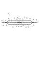
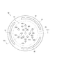
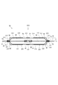
燃料室110に収容されるパルセーションダンパ50は、燃料室110の燃圧脈動を低減する。図1及び図2に示すように、パルセーションダンパ50は、第1ダイアフラム51、第2ダイアフラム61、中間部材としてのプレート80、及び弾性部材40を備えている。
第1ダイアフラム51および第2ダイアフラム61は、例えばステンレス等、耐力および疲労限界の高い金属板をプレス加工することで皿状に形成されている。
第1ダイアフラム51は、燃料室110の燃圧脈動により弾性変形可能な第1可動部52、及び第1可動部52の外縁に設けられる環状の第1外縁部53を有する。第2ダイアフラム61も、第1ダイアフラム51と同様の板厚、形状に形成された第2可動部62及び第2外縁部63を有する。
なお、図2では、第1ダイアフラム51を除き、第1外縁部53の位置を破線で示している。
第1可動部52の中央の円板状の領域を第1円板部54と称し、その外側の曲面状の領域を第1曲面部55と称する。第2可動部62の中央の円板状の領域を第2円板部64と称し、その外側の曲面状の領域を第2曲面部65と称する。
The
The
The
In FIG. 2, the position of the first
The disc-shaped region at the center of the first
第1ダイアフラム51と第2ダイアフラム61との間にプレート80が設けられている。プレート80は、例えばステンレスから円板状に形成される。プレート80は、第1外縁部53と第2外縁部63との間に挟まれている。
第1外縁部53と第2外縁部63とプレート80とは、板厚方向から周方向に連続して溶接される。あるいは、第1外縁部53の外周とプレート80とが径方向から周方向に連続して溶接され、第2外縁部63の外周とプレート80とが径方向から周方向に連続して溶接される。これにより、第1ダイアフラム51と第2ダイアフラム61との間に、密閉された密閉空間60が形成される。プレート80は、密閉空間60に延びると共に、第1外縁部53及び第2外縁部63の径外方向に延びている。
A
The first
密閉空間60の気圧は、内燃機関の作動に必要な最低燃料圧力以上で燃料に発生するベーパを抑制可能な気圧である。2枚のダイアフラム51、61の板厚、材質、外径、及び密閉空間60に封入されるガス封入圧を、耐久性或いはその他の要求性能に応じて適宜設定することで、パルセーションダンパ50のばね常数が設定される。そして、このばね常数により、パルセーションダンパ50が低減する脈動周波数及び脈動減衰性能が決定される。
本実施形態では、密閉空間60のガス封入圧は、可変燃圧システムの低圧時における燃料室110の燃料圧力に対応して設定されている。
第1可動部52と第2可動部62とは、燃料室110の圧力脈動によって振幅運動する。これにより、燃料室110の容積が変化し、燃料室110を流通する燃料の圧力脈動が減衰される。
The air pressure in the sealed
In the present embodiment, the gas filling pressure of the sealed
The first
プレート80は、第1外縁部53及び第2外縁部63から径外方向へ延びる環状の取付部81を有している。取付部81は、ダンパハウジング111と蓋部材12との間に挟まれ、固定される。これにより、パルセーションダンパ50は燃料室110に設置される。
プレート80の取付部81には、板厚方向に通じる流路82が設けられている。流路82は、パルセーションダンパ50の周方向に略均等に3か所設けられている。この流路82を通じてパルセーションダンパ50の上側と下側の燃料室110を燃料が流れる。
The
The
プレート80には、パルセーションダンパ50の軸を中心として板厚方向に通じる円形の孔が設けられている。プレート80の孔には、第1ダイアフラム51側から第1弾性部材41が取り付けられ、第2ダイアフラム61側から第2弾性部材42が取り付けられている。第1弾性部材41と第2弾性部材42とは、パルセーションダンパ50の中心軸上に設けられる。本実施形態では、第1弾性部材41と第2弾性部材42とが特許請求の範囲に記載の「弾性部材」に相当する。
The
第1弾性部材41は、第1筒部43、及びこの第1筒部43の軸方向第1可動部52側から径外方向に延びる第1フランジ部44を有する。
第2弾性部材42は、第2筒部45、及びこの第2筒部45の軸方向第2可動部62側から径外方向に延びる第2フランジ部46を有する。
第1弾性部材41と第2弾性部材42とプレート80との組付けにおいて、第1筒部43の径外方向の外壁と、第2筒部45の径内方向の内壁とが嵌合する。第1フランジ部44がプレート80の第1ダイアフラム51側の面に当接し、第2フランジ部46がプレート80の第2ダイアフラム61側の面に当接する。また、第2筒部45の軸方向第1可動部52側の端面と第1フランジ部44とが当接する。これにより、第1弾性部材41と第2弾性部材42とがプレート80に取り付けられる。
なお、第1弾性部材41と第2弾性部材42は、接着、圧着、焼き付け等によりプレート80に取り付けてもよい。
第1筒部43は、軸方向に通じる連通孔47を有する。連通孔47は、プレート80と第1ダイアフラム51とにより区画される第1の密閉空間601と、プレート80と第2ダイアフラム61とにより区画される第2の密閉空間602とを連通している。これにより、第1の密閉空間601と第2の密閉空間602とのガス封入圧が略同じになる。
The first
The second
In the assembly of the first
The first
The
続いて、吸入弁部30について図4を参照して説明する。
ポンプハウジング11には、シリンダ14の中心軸と略垂直に筒部15が設けられている。筒部15の内側に供給通路100が形成されている。供給通路100は燃料室110と加圧室121とを連通している。
弁ボディ31は、供給通路100に収容されている。弁ボディ31は、小径筒部32と大径筒部33を有している。大径筒部33の底部に凹テーパ状の弁座34が形成されている。
吸入弁35は弁ボディ31の大径筒部33の内側に配置されている。吸入弁35は、小径筒部32に設けられた孔36の内壁に案内されて往復移動する。吸入弁35の弁座34側に形成された凸テーパ状の弁シート37は、弁ボディ31の弁座34に着座および離座可能である。
Next, the
The
The
The
弁ボディ31の大径筒部33の内壁にストッパ39が固定されている。このストッパ39は、吸入弁35の開弁方向(図4の右方向)への移動を規制する。ストッパ39の内側と吸入弁35との間には第1スプリング21が設けられている。第1スプリング21は、吸入弁35を弁座34に着座させる方向、すなわち閉弁方向へ付勢している。
ストッパ39には、ストッパ39の軸に対して傾斜する傾斜通路104が周方向に複数形成されている。
A
The
次に電磁駆動部70について説明する。
電磁駆動部70は、コイル71、固定コア72、可動コア73、フランジ75などから構成される。
フランジ75は磁性体からなり、ポンプハウジング11の筒部15の端部を塞いでいる。フランジ75は、固定コア72及びコネクタ77を保持している。
フランジ75の加圧室121と反対側に磁性体からなる固定コア72が設けられている。固定コア72とフランジ75との間の磁気的な短絡を非磁性体からなる筒部材79が防止している。
固定コア72の径方向外側に樹脂製のスプール78が設けられている。スプール78の径外側にコイル71が巻回されている。
Next, the
The
The
A fixed
A resin spool 78 is provided on the radially outer side of the fixed
可動コア73は磁性体からなり、フランジ75の固定コア72側に設けられた収容室74に軸方向に往復移動可能に収容されている。
フランジ75の中央に設けられた孔の内壁には、筒状のガイド筒76が取り付けられている。
ニードル38は略円筒状に形成され、ガイド筒76の内壁に案内されて往復移動する。ニードル38は、一方の端部が可動コア73と一体に組み付けられ、他方の端部が吸入弁35の電磁駆動部70側の端面に当接するように設置されている。
The
A
The
固定コア72と可動コア73との間に第2スプリング22が設けられている。この第2スプリング22は、ストッパ39側の第1スプリング21が吸入弁35を閉弁方向に付勢する力よりも強い力で、可動コア73を吸入弁35側へ付勢している。
コイル71に通電していないとき、可動コア73は固定コア72に吸引されず、第2スプリング22の弾性力により互いに離れている。このため、可動コア73と一体のニードル38が吸入弁35側へ移動し、ニードル38の端面が吸入弁35を押圧することで吸入弁35が開弁する。
コイル71に通電されると、固定コア72、可動コア73、フランジ75などによって形成された磁気回路に磁束が流れ、可動コア73は固定コア72に吸引される。可動コア73と一体のニードル38が固定コア72側へ移動し、ニードル38は吸入弁35に対する押圧力を解除する。
A
When the
When the
次に吐出弁部90について説明する。
加圧室121と燃料出口91とを吐出通路114が連通している。
吐出弁92は、有底筒状に形成され、吐出通路114に往復移動可能に収容されている。吐出弁92は、吐出通路114に内壁に形成された弁座95に着座することで吐出通路114を閉塞し、弁座95から離座することで吐出通路114を開放する。
吐出弁92の燃料出口91側に筒状の規制部材93が設けられている。規制部材93は、吐出弁92の燃料出口91側への移動を規制する。
スプリング94は、一端が規制部材93に当接し、他端が吐出弁92に当接している。スプリング94は、吐出弁92を弁座95側へ付勢している。規制部材93の設置位置によって、スプリング94のばね荷重を設定し、吐出弁92の開弁圧を調整することができる。
Next, the
A
The
A cylindrical regulating
One end of the
加圧室121の燃料の圧力が上昇し、加圧室121側の燃料から吐出弁92が受ける力がスプリング94のばね力と弁座95の下流側の燃料から受ける力との和よりも大きくなると、吐出弁92は弁座95から離座する。これにより、加圧室121から吐出通路114を通り、燃料出口91から燃料が吐出される。
一方、加圧室121の燃料の圧力が低下し、加圧室121側の燃料から吐出弁92が受ける力がスプリング94のばね力と弁座95の下流側の燃料から受ける力との和よりも小さくなると、吐出弁92は弁座95に着座する。これにより、弁座95の下流側の燃料が加圧室121へ逆流することが防止される。
The pressure of the fuel in the pressurizing
On the other hand, the pressure of the fuel in the pressurizing
次に可変容積室122について説明する。
プランジャ13は、小径部131及び大径部133を有している。小径部131と大径部133との接続部分に段差面132が形成される。段差面132に向き合うように、略円環状のプランジャストッパ23が設けられている。
プランジャストッパ23は、加圧室121側の端面がポンプハウジング11に当接している。プランジャストッパ23の中央の孔をプランジャ13が挿通している。プランジャストッパ23は、中央の孔から径外方向に放射状に延びる複数の溝路28を有している。
プランジャ13の段差面132、小径部131の外壁、シリンダ14の内壁、プランジャストッパ23およびシール部材24に囲まれる略円環状の空間により可変容積室122が形成される。
Next, the
The
The
A
ポンプハウジング11には、シリンダ14が開口する側の外壁に、加圧室121側へ略円環状に凹む凹部105が設けられている。凹部105には、オイルシールホルダ25が嵌め込まれている。オイルシールホルダ25は、プランジャストッパ23との間にシール部材24を挟んで、ポンプハウジング11に固定されている。シール部材24は、内周のテフロンリング(「テフロン」は登録商標)と、外周のOリングとからなる。シール部材24は、小径部131周囲の燃料油膜の厚さを規制し、プランジャ13の摺動によるエンジンへの燃料のリークを抑制する。オイルシールホルダ25の加圧室121と反対側の端部には、オイルシール26が装着されている。オイルシール26は、小径部131周囲のオイル油膜の厚さを規制し、プランジャ13の摺動によるオイルのリークを抑制する。
The
オイルシールホルダ25とポンプハウジング11との間には、筒状通路106とこの筒状通路106に連通する環状通路107が形成されている。筒状通路106はプランジャストッパ23の溝路28に連通している。環状通路107はポンプハウジング11に形成された戻し通路108を経由して燃料室110に連通している。このように、溝路28、筒状通路106、環状通路107及び戻し通路108が順に連通することで、可変容積室122と燃料室110とが連通する。
Between the
次に、高圧ポンプ10の作動について説明する。
(1)吸入行程
カムシャフト7の回転により、プランジャ13が上死点から下死点に向かって下降すると、加圧室121の容積が増加し、燃料が減圧される。吐出弁92は弁座95に着座し、吐出通路114を閉塞する。
一方、吸入弁35は、加圧室121と供給通路100との差圧により、第1スプリング21の付勢力に抗して加圧室121側へ移動し、開弁状態となる。このとき、コイル71への通電は停止されているので、可動コア73とニードル38は第2スプリング22の付勢力により加圧室121側へ移動する。したがって、ニードル38と吸入弁35とが当接し、吸入弁35は開弁状態を維持する。これにより、燃料室110から供給通路100を経由し、加圧室121に燃料が吸入される。
Next, the operation of the high-
(1) Suction stroke When the
On the other hand, the
吸入行程では、プランジャ13の下降により、可変容積室122の容積が減少する。したがって、可変容積室122の燃料は、筒状通路106、環状通路107及び戻し通路108を経由し、燃料室110へ送り出される。
ここで、大径部133と可変容積室122の断面積比は概ね1:0.6である。したがって、加圧室121の容積の増加分と可変容積室122の容積の減少分の比も1:0.6となる。よって、加圧室121が吸入する燃料の約60%が可変容積室122から供給され、残りの約40%が燃料入口から吸入される。これにより、加圧室121への燃料の吸入効率が向上するとともに、燃圧脈動が低減される。
吸入行程では、燃料室110の燃料圧力が低下するので、第1ダイアフラム51の第1可動部52と第2ダイアフラム61の第2可動部62とは、互いに離れる方向へ変形する。
In the suction stroke, the volume of the
Here, the cross-sectional area ratio between the
In the intake stroke, the fuel pressure in the
(2)調量行程
カムシャフト7の回転により、プランジャ13が下死点から上死点に向かって上昇すると、加圧室121の容積が減少する。このとき、所定の時期まではコイル71への通電が停止されているので、第2スプリング22の付勢力によりニードル38と吸入弁35は開弁位置にある。これにより、供給通路100は開放された状態が維持される。このため、一度加圧室121に吸入された低圧燃料が供給通路100を経由し、燃料室110へ戻される。したがって、加圧室121の圧力は上昇しない。
(2) Metering stroke When the
調量行程では、プランジャ13の上昇により、可変容積室122の容積が増大する。したがって、燃料室110の燃料は、戻し通路108、環状通路107及び筒状通路106を経由し、可変容積室122へ流入する。
このとき、加圧室121が燃料室110側へ排出する低圧燃料の容積の約60%が、燃料室110から可変容積室122に吸入される。これにより、燃圧脈動の約60%が低減される。
調量行程では、燃料室110の燃料圧力が上昇するので、第1ダイアフラム51の第1可動部52と第2ダイアフラム61の第2可動部62とは、互いに近づく方向へ変形する。
In the metering stroke, the volume of the
At this time, about 60% of the volume of the low-pressure fuel discharged from the pressurizing
In the metering stroke, the fuel pressure in the
(3)加圧行程
プランジャ13が下死点から上死点に向かって上昇する途中の所定の時刻に、コイル71へ通電される。するとコイル71に発生する磁界により、固定コア72と可動コア73との間に磁気吸引力が発生する。この磁気吸引力が第2スプリング22の弾性力と第1スプリング21の弾性力との差よりも大きくなると、可動コア73とニードル38は固定コア72側(図3の左方向)へ移動する。これにより、吸入弁35に対するニードル38の押圧力が解除される。吸入弁35は、第1スプリング21の弾性力、及び加圧室121から燃料室110側へ排出される低圧燃料の流れによって生ずる力により、弁座34側へ移動する。したがって、吸入弁35は弁座34に着座し、供給通路100が閉塞される。
(3) Pressurization stroke The
吸入弁35が弁座34に着座した時から、加圧室121の燃料圧力は、プランジャ13の上死点に向かう上昇と共に高くなる。加圧室121の燃料圧力が吐出弁92に作用する力が、吐出通路114の燃料圧力が吐出弁92に作用する力およびスプリング94の付勢力よりも大きくなると、吐出弁92が開弁する。これにより、加圧室121で加圧された高圧燃料は吐出通路114を経由して燃料出口91から吐出する。
なお、加圧行程の途中でコイル71への通電が停止される。加圧室121の燃料圧力が吸入弁35に作用する力は、第2スプリング22の付勢力より大きいので、吸入弁35は閉弁状態を維持する。
From the time when the
Note that energization of the
高圧ポンプ10は、(1)から(3)の行程を繰り返し、内燃機関に必要な量の燃料を加圧して吐出する。
コイル71へ通電するタイミングを早くすれば、調量行程の時間が短くなると共に、加圧行程の時間が長くなる。これにより、加圧室121から供給通路100へ戻される燃料が少なくなり、吐出通路114から吐出される燃料が多くなる。
一方、コイル71へ通電するタイミングを遅くすれば、調量行程の時間が長くなると共に、吐出行程の時間が短くなる。これにより、加圧室121から供給通路100へ戻される燃料が多くなり、吐出通路114から吐出される燃料が少なくなる。
このように、コイル71へ通電するタイミングを制御することで、高圧ポンプ10から吐出される燃料の量を内燃機関が必要とする量に制御することができる。
The high-
If the timing of energizing the
On the other hand, if the timing of energizing the
Thus, by controlling the timing of energizing the
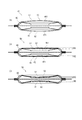
次に、本実施形態のパルセーションダンパ50の動作を図5を参照して説明する。
本実施形態において、パルセーションダンパ50は、密閉空間60のガス封入圧が、可変燃圧システムの低圧時における燃料室110の燃料圧力と同等か若干低めに設定されている。
図5(A)は、車両のエンジンが停止しているときなど、高圧ポンプ10が作動していないときのパルセーションダンパ50の状態を示している。このとき、燃料室110の燃料圧力は、大気圧と略同等であるので、第1ダイアフラム51の第1可動部52と第2ダイアフラム61の第2可動部62とは、互いに離れる方向に変位している。
Next, the operation of the
In the present embodiment, the
FIG. 5A shows the state of the
図5(B)は、可変燃圧システムの低圧時におけるパルセーションダンパ50の動作を示している。第1可動部52と第2可動部62とは、平行状態、またはそれよりも、互いに僅かに近づいた状態を基準位置として振幅動作する。図5(B)では、低圧時の第1可動部52と第2可動部62の振幅動作の波高をそれぞれH1、H2に示している。
FIG. 5B shows the operation of the
図5(C)は、可変燃圧システムの通常圧時におけるパルセーションダンパ50の動作を示している。第1可動部52と第2可動部62とは、低圧時よりも互いに近づく方向に変位している。第1可動部52と第2可動部62は、その状態を基準位置として振幅動作する。図5(C)では、通常圧時の第1可動部52と第2可動部62の振幅動作の波高をそれぞれH3、H4に示している。
FIG. 5C shows the operation of the
図5(D)は、可変燃圧システムの高圧時におけるパルセーションダンパ50の動作を示している。第1可動部52と第2可動部62とは、通常圧時よりも互いに近づく方向に変位している。第1可動部52と第2可動部62は、弾性部材40に当接している。弾性部材40の第1ダイアフラム51側の端面は、第1ダイアフラム51の内壁の形状に沿って曲面状に弾性変形している。弾性部材40の第2ダイアフラム61側の端面も、第2ダイアフラム61の内壁の形状に沿って曲面状に弾性変形している。
ここで、弾性部材40は、その弾性係数が第1ダイアフラム51及び第2ダイアフラム61と共に振幅動作可能な程度に小さい。このため、第1ダイアフラム51と第2ダイアフラム61は、弾性部材40に当接した状態を基準として、弾性部材40と共に振幅動作する。図5(D)では、高圧時の第1可動部52と第2可動部62の振幅動作の振幅動作の波高をそれぞれH5、H6に示している。この時のばね定数kは、第1ダイアフラム51又は第2ダイアフラム61のばね定数をk1とし、弾性部材40のばね定数をk2とすると、k=k1+k2 である。
FIG. 5D shows the operation of the
Here, the
本実施形態では、以下の作用効果を奏する。
(1)本実施形態では、可変燃圧システムの高圧時に第1可動部52と弾性部材40、及び第2可動部62と弾性部材40とが当接する。これにより、第1可動部52と第2可動部62との接触を避けることができる。したがって、第1、第2ダイアフラム51、61の疲労強度の低下を抑制し、耐用期間を長くすることができる。
(2)第1可動部52と第2可動部62とはその中央部分が最も変位する。このため、弾性部材40は、第1ダイアフラム51及び第2ダイアフラム61の中心軸上に設けられる。したがって、弾性部材40は、第1可動部52と第2可動部62との接触を確実に防ぐことができる。
In the present embodiment, the following effects are obtained.
(1) In the present embodiment, the first
(2) The central portions of the first
(3)本実施形態では、パルセーションダンパ50の密閉空間60のガス封入圧を、可変燃圧システムの低圧時における燃料室110の燃料圧力に対応した値に設定している。これにより、パルセーションダンパ50は、低圧時および通常圧時において、高い脈動低減効果を発揮することができる。
(4)本実施形態では、弾性部材40の弾性係数を小さい値に設定している。これにより、弾性部材40に当接した第1ダイアフラム51と第2ダイアフラム61は、弾性部材40と共に振幅動作する。このため、パルセーションダンパ50は、高圧時において、高い脈動低減効果を発揮することができる。したがって、パルセーションダンパ50は、燃料室に供給される燃料圧力差が大きく変化する環境下に対応しつつ、高い脈動低減効果を得ることができる。
(3) In this embodiment, the gas filling pressure in the sealed
(4) In this embodiment, the elastic coefficient of the
(5)本実施形態では、第1ダイアフラム51又は第2ダイアフラム61に弾性部材40を設けることなく、プレート80に弾性部材40を設けることで、第1ダイアフラム51の共振周波数と第2ダイアフラム61の共振周波数とを略同じ値にすることができる。したがって、パルセーションダンパ50は、2枚のダイアフラム51、61の振幅動作により、高い脈動低減効果を得ることができる。
(6)本実施形態では、弾性部材40の連通孔47により、第1の密閉空間601と第2の密閉空間602とのガス封入圧が略同じ値になる。これにより、第1ダイアフラム51の共振周波数と第2ダイアフラム61の共振周波数とを略同じ値にすることができる。したがって、2枚のダイアフラム51、61の燃圧脈動効果が合算されることで、パルセーションダンパ50は高い脈動低減効果を発揮することができる。
(5) In this embodiment, by providing the
(6) In this embodiment, the gas sealing pressures of the first sealed
(7)本実施形態では、パルセーションダンパ50を燃料室110に設置する際、取付部81をダンパハウジング111と蓋部材12との間に挟むことで、第1、第2ダイアフラム51、61に過度の応力が作用することを抑制することができる。これにより、パルセーションダンパ50の脈動低減効果を向上することができる。
(7) In this embodiment, when the
(第2実施形態)
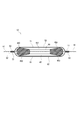
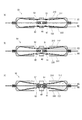
本発明の第2実施形態によるパルセーションダンパ50を図6に示す。以下、複数の実施形態において、上述した第1実施形態と実質的に同一の構成には同一の符号を付して説明を省略する。本実施形態では、弾性部材40は連通孔47を有していない。ただし、例えば同一気圧の作業室内で、プレート80と第1ダイアフラム51と第2ダイアフラム61との溶接を行うことで、第1の密閉空間601のガス封入圧と第2の密閉空間602のガス封入圧とを略同じ値にすることが可能である。
本実施形態においても、上述した第1実施形態と同様の作用効果を奏することができる。
(Second Embodiment)
A
Also in this embodiment, the same operational effects as those of the first embodiment described above can be achieved.
(第3実施形態)
本発明の第3実施形態によるパルセーションダンパ50を図7及び図8に示す。
本実施形態では、プレート80に複数個の弾性部材が設けられている。
弾性部材は、第1ダイアフラム51及び第2ダイアフラム61の中心軸上に設けられる中央弾性部材410と、中央弾性部材410の径外側に設けられる6個の環状弾性部材群420と、環状弾性部材群420の径外側に設けられる6個の外側環状弾性部材群430とからなる。本実施形態では、これらの複数個の弾性部材が特許請求の範囲に記載の「弾性部材」に相当する。
中央弾性部材410と環状弾性部材群420と外側環状弾性部材群430とは、パルセーションダンパ50の軸を中心とした同心円状に個設けられる。弾性部材は、接着、圧着、焼き付け、又はプレート80に設けられた孔に差し込まれる等の方法でプレート80に取り付けられる。プレート80の第1ダイアフラム51側の弾性部材と、第2ダイアフラム61側の弾性部材とは略同じ位置に設けられている。
(Third embodiment)
A
In the present embodiment, the
The elastic members are a central
The central
複数個の弾性部材の第1可動部52側の端部は、第1可動部52がプレート80に近づく方向に変位したときの第1可動部52の内壁の形状に沿って形成されている。つまり、中央弾性部材410が最も低く形成され、次に環状弾性部材群420がプレート80から高く形成され、さらに外側環状弾性部材群430がプレート80から高く形成されている。これにより、第1可動部52がプレート80に近づく方向に変位したとき、複数個の弾性部材は、第1可動部52に内壁に略同時に当接する。そして、第1可動部52に対し、略均等に弾性力を印加する。
また、複数個の弾性部材の第2可動部62側の端部も、第2可動部62がプレート80に近づく方向に変位したときの第2可動部62の内壁の形状に沿って形成されている。これにより、第2可動部62がプレート80に近づく方向に変位したとき、複数個の弾性部材は、第2可動部62に内壁に略同時に当接する。そして、第2可動部62に対し、略均等に弾性力を印加する。
本実施形態では、弾性部材が単数の場合の第1、第2実施形態と比較して、弾性部材の弾性係数を小さく設定することが可能である。これにより、複数個の弾性部材と第1可動部52と第2可動部62とが共に振幅動作するときの脈動低減効果を高めることができる。
また本実施例では、弾性部材410,420,430の高さをそれぞれ適宜設定することにより、弾性部材と第1可動部及び第2可動部との接触変位を調整可能である。これにより、第1可動部と第2可動部の変位に対する弾性係数を任意に設定可能となる。よってパルセーションダンパの脈動抑制特性をダイアフラムの材質、板厚、可動部径、ガス圧以外の要素にて任意に設定することができるため、幅広い使用範囲での使用が可能となる。
The ends of the plurality of elastic members on the first
Further, the end portions of the plurality of elastic members on the second
In the present embodiment, the elastic coefficient of the elastic member can be set smaller than in the first and second embodiments where the number of elastic members is single. Thereby, the pulsation reduction effect when the plurality of elastic members, the first
Further, in this embodiment, the contact displacement between the elastic member and the first movable portion and the second movable portion can be adjusted by appropriately setting the heights of the
(第4実施形態)
本発明の第4実施形態によるパルセーションダンパ50を図9及び図10に示す。本実施形態においても、中央弾性部材410、6個の環状弾性部材群420、及び6個の外側環状弾性部材群430が特許請求の範囲に記載の「弾性部材」に相当する。
本実施形態では、6個の環状弾性部材群420は、中段部421、及びこの中段部421よりも小径の上段部422を有する。
6個の外側環状弾性部材群430は、下段部431、及びこの下段部431よりも小径の中段部432、及びこの中段部432よりも小径の上段部433を有する。
なお、図9及び図10では、上述した環状弾性部材群420の中段部421及び上段部422は環状弾性部材群420において実質的に同一の構成であり、外側環状弾性部材群430の下段部431、中段部432及び上段部433は外側環状弾性部材群430において実質的に同一の構成であるので、符号を省略してある。
弾性部材は、接着、圧着、焼き付け、又はプレート80に設けられた孔に差し込まれる等の方法でプレート80に取り付けられる。プレート80の第1ダイアフラム51側の弾性部材と、第2ダイアフラム61側の弾性部材とは略同じ位置に設けられている。
本実施形態では、環状弾性部材群420及び外側環状弾性部材群430の上段部422、433又は中段部421、432を小径に形成することで、複数個の弾性部材の第1可動部52側の端部及び第2可動部62側の端部のばね定数を小さく設定することが可能である。これにより、複数個の弾性部材と第1可動部52と第2可動部62とが共に振幅動作するときの脈動低減効果を高めることができる。
また、中央弾性部材410及び、環状弾性部材420,430の高さを適宜設定することで、前述したようにパルセーションダンパの脈動抑制特性を任意に設定可能である。
(Fourth embodiment)
A
In the present embodiment, the six annular
The six outer annular
9 and 10, the
The elastic member is attached to the
In the present embodiment, the
Further, by appropriately setting the heights of the central
(第5実施形態)
本発明の第5実施形態によるパルセーションダンパ50を図11及び図12に示す。本実施形態においても、中央弾性部材410、6個の環状弾性部材群420、及び6個の外側環状弾性部材群430が特許請求の範囲に記載の「弾性部材」に相当する。
本実施形態では、環状弾性部材群420及び外側環状弾性部材群430は、第1ダイアフラム51側の端部と第2ダイアフラム61側の端部とが径内方向に曲折している。これにより、環状弾性部材群420及び外側環状弾性部材群430のばね定数を小さく設定することが可能である。したがって、パルセーションダンパ50の脈動低減効果を高めることができる。
また、本実施形態では、環状弾性部材群420及び外側環状弾性部材群430は、第1可動部52側の端部と第2可動部62側の端部とが曲面に形成されている。これにより、第1可動部52又は第2可動部62と弾性部材とが当接したときの面圧が低減され、第1、第2ダイアフラム51、61に応力集中が生じることを抑制することができる。
また、中央弾性部材410及び、環状弾性部材420,外側環状弾性部材群430の高さを適宜設定することで、前述したようにパルセーションダンパの脈動抑制特性を任意に設定可能である。
(Fifth embodiment)
11 and 12 show a
In the present embodiment, in the annular
In the present embodiment, the annular
Further, by appropriately setting the heights of the central
(第6実施形態)
本発明の第6実施形態によるパルセーションダンパ50を図13及び図14に示す。
本実施形態では、弾性部材は、第1ダイアフラム51及び第2ダイアフラム61の中心軸上に設けられる中央弾性部材410と、中央弾性部材410の径外側に環状に設けられる環状弾性部材440と、環状弾性部材440の径外側に環状に設けられる外側環状弾性部材450とからなる。本実施形態では、これらの弾性部材が特許請求の範囲に記載の「弾性部材」に相当する。
中央弾性部材410と環状弾性部材440と外側環状弾性部材450とは、第1ダイアフラム51及び第2ダイアフラム61の軸を中心とした同心円状に個設けられる。弾性部材は、接着、圧着、焼き付け、又はプレート80に設けられた孔に差し込まれる等の方法でプレート80に取り付けられる。プレート80の第1ダイアフラム51側の弾性部材と、第2ダイアフラム61側の弾性部材とは略同じ位置に設けられている。
(Sixth embodiment)
A
In the present embodiment, the elastic members are a central
The central
本実施形態においても、複数個の弾性部材の第1可動部52側の端部は、第1可動部52がプレート80に近づく方向に変位したときの第1可動部52の内壁の形状に沿って形成されている。これにより、第1可動部52がプレート80に近づく方向に変位したとき、複数個の弾性部材は、第1可動部52に内壁に略同時に当接する。そして、第1可動部52に対し、略均等に弾性力を印加することができる。
また、弾性部材の第2可動部62側の端部も、第2可動部62がプレート80に近づく方向に変位したときの第2可動部62の内壁の形状に沿って形成されている。これにより、第2可動部62がプレート80に近づく方向に変位したとき、複数個の弾性部材は、第2可動部62に内壁に略同時に当接する。そして、第2可動部62に対し、略均等に弾性力を印加することができる。
したがって、第1、第2可動部52、62と複数個の弾性部材とが当接したときの面圧が低減され、第1、第2ダイアフラム51、61に応力集中が生じることを抑制することができる。
また、中央弾性部材410及び、環状弾性部材440,外側環状弾性部材450の高さを適宜設定することで、前述したようにパルセーションダンパの脈動抑制特性を任意に設定可能である。
Also in the present embodiment, the end portions of the plurality of elastic members on the first
Further, the end of the elastic member on the second
Therefore, the surface pressure when the first and second
Further, by appropriately setting the heights of the central
(第7実施形態)
本発明の第7実施形態によるパルセーションダンパ50を図15及び図16に示す。
本実施形態では、弾性部材は、プレート80の第1ダイアフラム51側に設けられる第1弾性部材460と、プレート80の第2ダイアフラム61側に設けられる第2弾性部材470とから構成される。本実施形態では、第1弾性部材460と第2弾性部材470とが特許請求の範囲に記載の「弾性部材」に相当する。
第1弾性部材460と第2弾性部材470は、例えばステンレスからなる板材をプレス加工することで環状に形成される。
第1弾性部材460は、第1支持部461、第1接続部462及び第1挟持部463を有する。
第1支持部461は、第1可動部52側の端面が径外方向から径内方向へ向けて第2可動部62側へ傾斜するように形成される。第1支持部461は、第1可動部52と第2可動部62とが互いに近づく方向へ変位したとき、第1可動部52の外縁を支持する。第1支持部461の径内方向には穴が設けられている。
第1接続部462は、第1支持部461の外縁から第1外縁部53側へ延びている。
第1挟持部463は、第1接続部462の外縁から第1外縁部53と第2外縁部63との間に延びている。
第2弾性部材470もまた、第2支持部471、第2接続部472及び第2挟持部473を有する。第2支持部471、第2接続部472及び第2挟持部473の構成は、第1支持部461、第1接続部462及び第1挟持部463の構成と実質的に同一であるので説明を省略する。
第1外縁部53、第1挟持部463、プレート80、第2挟持部473および第2外縁部63は、この順に重なり、板厚方向から周方向に連続して溶接される。あるいは、第1外縁部53及び第1挟持部463の外周とプレート80とが径方向から周方向に連続して溶接され、第2外縁部63及び第2挟持部473の外周とプレート80とが径方向から周方向に連続して溶接される。
(Seventh embodiment)
A
In the present embodiment, the elastic member includes a first
The first
The first
The
The
The
The second
The 1st
次に、本実施形態のパルセーションダンパ50の動作について図16を参照して説明する。
本実施形態においても、パルセーションダンパ50は、密閉空間60のガス封入圧が、可変燃圧システムの低圧時における燃料室110の燃料圧力に対応して設定されている。
図16(A)は、車両のエンジンが停止しているときなど、高圧ポンプ10が作動していないときのパルセーションダンパ50の状態を示している。このとき、燃料室110の燃料圧力は、大気圧と略同等であるので、第1可動部52と第2可動部62とは、互いに離れる方向に変位している。
Next, the operation of the
Also in the present embodiment, in the
FIG. 16A shows the state of the
図16(B)は、可変燃圧システムの低圧時におけるパルセーションダンパ50の動作を示している。第1可動部52と第2可動部62とは、平行状態、またはそれよりも、互いに僅かに近づいた状態を基準として振幅動作する。図16(B)では、低圧時の第1可動部52と第2可動部62の振幅動作の波高をそれぞれH1、H2に示している。
FIG. 16B shows the operation of the
図16(C)は、可変燃圧システムの高圧時におけるパルセーションダンパ50の動作を示している。第1可動部52と第2可動部62とは、互いに近づく方向に変位している。第1可動部52は、その外縁が第1支持部461に支持されている。第2可動部62は、その外縁が第2支持部471に支持されている。第1支持部461と第2支持部471は、第1可動部52の中央部と第2可動部62の中央部との接触を防止している。
第1可動部52と第2可動部62とは、その外縁よりも径内側が第1、第2支持部461、471に支持されることなく、自由に振幅動作することが可能である。
また、第1支持部461と第2支持部471とは、第1可動部52と第2可動部62と共に振幅動作する。図16(C)では、高圧時の第1可動部52と第2可動部62の振幅動作の波高をそれぞれH5、H6に示している。この時のばね定数kは、第1ダイアフラム51又は第2ダイアフラム61のばね定数をk1とし、第1支持部461又は第2支持部471のばね定数をk2とすると、k=k1+k2 である。
FIG. 16C shows the operation of the
The first
Further, the
本実施形態では、可変燃圧システムの高圧時に第1可動部52と第1支持部461、及び第2可動部62と第2支持部471とが当接する。これにより、第1可動部52と第2可動部62との接触を避けることができる。したがって、第1、第2ダイアフラム51、61の疲労強度の低下を抑制し、パルセーションダンパ50の耐用期間を長くすることができる。
本実施形態では第1可動部52及び第2可動部62は、第1、第2支持部461、471に支持される外縁よりも径内側が自由に振幅動作する。このため、パルセーションダンパ50は、高い脈動低減効果を得ることができる。
また、本実施形態では、弾性部材の弾性係数を小さい値に設定することで、第1、第2支持部461、471と第1可動部52と第2可動部62とが共に振幅動作する。これにより、パルセーションダンパ50は、高圧時において、高い脈動低減効果を発揮することができる。
また、支持部材461,471の形状を適宜設定することで、前述したようにパルセーションダンパの脈動抑制特性を任意に設定可能である。
In the present embodiment, the first
In the present embodiment, the first
Further, in the present embodiment, by setting the elastic coefficient of the elastic member to a small value, the first and
Further, by appropriately setting the shapes of the
(第8実施形態)
本発明の第8実施形態によるパルセーションダンパ50を図17に示す。
本実施形態では、プレート80が設けられていない。しかし、この構成であっても、第1挟持部463と第2挟持部473とが第1外縁部53と第2外縁部63との間に挟まれ、共に溶接されることで、第1、第2弾性部材460、470は密閉空間60に設置される。
本実施形態では、第7実施形態と比較して、プレート80の板厚相当分、第1可動部52と第2可動部62との距離を近くすることで、パルセーションダンパ50の軸方向の体格を小さくすることができる。
(Eighth embodiment)
A
In this embodiment, the
In the present embodiment, the axial distance of the
(第9実施形態)
本発明の第9実施形態によるパルセーションダンパ50を図18に示す。
本実施形態では、弾性部材が例えばゴムまたは樹脂などから形成されている。本実施形態においても、第1弾性部材480と第2弾性部材490とが特許請求の範囲に記載の「弾性部材」に相当する。プレート80には、板厚方向に通じる孔が設けられている。プレート80の孔を通じて第1弾性部材480と第2弾性部材490とが一体で形成されている。
第1弾性部材480は第1支持部481を有し、第2弾性部材490は第2支持部491を有する。
第1支持部481は、第1ダイアフラム51側の端面が径外方向から径内方向へ向けて第2可動部62側へ傾斜するように形成される。第1支持部481は、第1可動部52と第2可動部62とが互いに近づく方向へ変位したとき、第1可動部52の外縁を支持する。第1支持部481の径内方向には穴が設けられている。
第2支持部491の構成は、第1支持部481の構成と実質的に同一である。
(Ninth embodiment)
A
In the present embodiment, the elastic member is made of, for example, rubber or resin. Also in this embodiment, the 1st
The first
The
The configuration of the
本実施形態においても、可変燃圧システムの高圧時、第1可動部52と第2可動部62とが互いに近づく方向に変位すると、第1可動部52の外縁が第1支持部481に支持され、第2可動部62の外縁が第2支持部491に支持される。これにより、第1可動部52と第2可動部62との接触が防止される。
第1可動部52及び第2可動部62は、第1、第2支持部481、491に支持される外縁よりも径内側が自由に振幅動作する。このため、高い脈動低減効果を得ることができる。
また、本実施形態では、弾性部材の弾性係数を小さい値に設定することで、第1、第2支持部481、491と第1、第2可動部52、62とが共に振幅動作する。これにより、パルセーションダンパ50は、高圧時において、高い脈動低減効果を発揮することができる。
Also in this embodiment, when the variable fuel pressure system is at a high pressure, when the first
The first
Further, in the present embodiment, by setting the elastic coefficient of the elastic member to a small value, the first and
(第10実施形態)
本発明の第10実施形態によるパルセーションダンパ50を図19〜図23に示す。
本実施形態では、第1ダイアフラム51の第2ダイアフラム61と反対側に第1カバー部材210が設けられ、第2ダイアフラム61の第1ダイアフラム51と反対側に第2カバー部材220が設けられている。第1カバー部材210および第2カバー部材220は、例えばステンレス等の所定の剛性を有する金属をプレス加工などすることにより形成される。
第1カバー部材210は、第1環状部211及び第1規制部212を有する。第1環状部211は、環状に形成され、第1外縁部53の第2外縁部63と反対側に設けられる。第1規制部212は、第1環状部211の内縁から第1ダイアフラム51の第1曲面部55の外側に延びる第1腕部213と、第1腕部213の第1環状部211の反対側の端部から径内方向へ延びる第1当接部214とからなる。第1規制部212は、第1環状部211の周方向に複数個設けられている。
(10th Embodiment)
A
In the present embodiment, a
The
ここで、第1外縁部53とプレート80との当接面を含む平面を仮想平面Sする。また、パルセーションダンパ50の密閉空間60とパルセーションダンパ50の外側との気圧が同等の場合における仮想平面Sと第1可動部52の外側端面の中心Oとの距離を距離dとする。
第1カバー部材210は、第1当接部214の第1ダイアフラム51側の端面と仮想平面Sとの距離が距離d1となるように形成されている。ここで、d1>dの関係がある。これにより、第1規制部212は、第1可動部52の第2可動部62と反対側への膨らみを規制することが可能である。
Here, a plane including the contact surface between the first
The
第2カバー部材220も第1カバー部材210と同様の形状の第2環状部221及び第2規制部222を有する。第2カバー部材220は、第2当接部224の第2ダイアフラム61側の端面とプレート80の第2ダイアフラム61側の端面との距離が距離d1となるように形成されている。ここで、d1>dの関係がある。これにより、第2規制部222は、第2可動部62の第1可動部52と反対側への膨らみを規制することが可能である。
The
次に、本実施形態のパルセーションダンパ50の動作を図22を参照して説明する。
本実施形態において、パルセーションダンパ50は、密閉空間60のガス封入圧が、可変燃圧システムの低圧時における燃料室110の燃料圧力に対応して設定されている。
図22(A)は、可変燃圧システムの低圧時におけるパルセーションダンパ50の動作を示している。第1可動部52と第2可動部62とは、互いに近づいた状態を基準位置として振幅動作する。図22(A)では、低圧時の第1可動部52と第2可動部62の振幅動作の波高をそれぞれH1、H2に示している。
Next, the operation of the
In the present embodiment, in the
FIG. 22A shows the operation of the
図22(B)は、可変燃圧システムの通常圧時におけるパルセーションダンパ50の動作を示している。第1可動部52と第2可動部62とは、低圧時よりも互いに近づく方向に変位している。第1可動部52と第2可動部62は、その状態を基準位置として振幅動作する。図22(B)では、通常圧時の第1可動部52と第2可動部62の振幅動作の波高をそれぞれH3、H4に示している。
FIG. 22B shows the operation of the
図22(C)は、可変燃圧システムの高圧時におけるパルセーションダンパ50の動作を示している。第1可動部52と第2可動部62とは、通常圧時よりも互いに近づく方向に変位している。第1可動部52と第2可動部62は、弾性部材40に当接している。弾性部材40の第1ダイアフラム51側の端面は、第1ダイアフラム51の内壁の形状に沿って曲面状に弾性変形している。弾性部材40の第2ダイアフラム61側の端面も、第2ダイアフラム61の内壁の形状に沿って曲面状に弾性変形している。
ここで、弾性部材40は、その弾性係数が第1ダイアフラム51及び第2ダイアフラム61と共に振幅動作可能な程度に小さい。このため、第1ダイアフラム51と第2ダイアフラム61は、弾性部材40に当接した状態を基準として、弾性部材40と共に振幅動作する。図22(C)では、高圧時の第1可動部52と第2可動部62の振幅動作の波高をそれぞれH5、H6に示している。この時のばね定数kは、第1ダイアフラム51又は第2ダイアフラム61のばね定数をk1とし、弾性部材40のばね定数をk2とすると、k=k1+k2 である。
FIG. 22C shows the operation of the
Here, the
次に、高圧ポンプ10の作動時等にパルセーションダンパ50に生じる応力について説明する。
本実施形態のパルセーションダンパ50の第1ダイアフラム51の変位を図23(A)に示し、そのときに第1ダイアフラム51に生じる応力を図23(B)に示す。
図23(A)の時刻t0の左側は、車両のエンジンが停止しているときなどに高圧ポンプ10が作動していない状態(以下「非作動状態」という)である。時刻t0から時刻t1で高圧ポンプ10は非作動状態から作動開始状態に移行する。時刻t1以降、高圧ポンプ10は作動中状態となる。
第1ダイアフラム51は第1規制部212により膨らみが規制されているので、非作動状態において、第1可動部52の外側端面の中心Oと仮想平面Sとの距離はd1である。非作動状態から作動開始状態に移行すると、燃料室110の燃圧が高くなることで、第1可動部52と第2可動部62とが互いに近づく方向に変位し、中心Oと仮想平面Sとの距離が小さくなりdとなる。作動中状態になると、第1可動部52と第2可動部62とは、燃料室110の燃圧脈動により振幅動作を繰り返す。このため、第1ダイアフラム51の中心Oと仮想平面Sとの距離は、一定の範囲で変動する。
Next, the stress generated in the
FIG. 23A shows the displacement of the
The left side of time t0 in FIG. 23A is a state where the high-
Since the swelling of the
図23(B)では、中心Oと仮想平面Sとの距離がdよりも大きいときに第1ダイアフラム51に生じる応力を縦軸の正側(+)に示し、中心Oと仮想平面Sとの距離がdよりも小さいときに第1ダイアフラム51に生じる応力を縦軸の負側(−)に示す。
第1ダイアフラム51は第1規制部212により膨らみがd1に規制されているため、非作動状態のときに第1ダイアフラム51に生じる応力はσ1である。非作動状態から作動開始状態に移行すると、第1ダイアフラム51に生じる応力は0になる。作動中状態になると、第1ダイアフラム51に生じる応力は、一定の範囲で変動する。
なお、第2ダイアフラム61の変位、及び第2ダイアフラム61に生じる応力も、第1ダイアフラム51の変位及び応力と同様に生じる。
In FIG. 23B, the stress generated in the
Since the swelling of the
The displacement of the
ここで、比較例のパルセーションダンパに生じる応力について説明する。
比較例の図示しないパルセーションダンパは、第1カバー部材及び第2カバー部材を備えていない。比較例のパルセーションダンパの密閉空間の気圧は、本実施形態と同様の気圧である。パルセーションダンパは、大気圧に置かれた状態において第1可動部と第2可動部とが互いに遠ざかり、膨らんだ状態となる。
Here, the stress which arises in the pulsation damper of a comparative example is demonstrated.
The pulsation damper (not shown) of the comparative example does not include the first cover member and the second cover member. The air pressure in the sealed space of the pulsation damper of the comparative example is the same as that in the present embodiment. In the state where the pulsation damper is placed at atmospheric pressure, the first movable portion and the second movable portion are moved away from each other and swelled.
比較例のパルセーションダンパの第1ダイアフラムの変位を図24(A)に示し、そのときに第1ダイアフラムに生じる応力を図24(B)に示す。
図24(A)の時刻t0の左側は高圧ポンプの非作動状態である。時刻t0から時刻t1で高圧ポンプは非作動状態から作動開始状態に移行する。時刻t1以降、高圧ポンプは作動中状態となる。
比較例では、非作動状態において、第1ダイアフラムの中心Oと仮想平面Sとの距離をd+Δdとして表わす。非作動状態から作動開始状態に移行すると、第1可動部と第2可動部とが互いに近づく方向に変位することで、中心Oと仮想平面Sとの距離が小さくなり、dとなる。作動中状態になると、第1可動部と第2可動部とが振幅動作する。このため、第1ダイアフラムの中心Oと仮想平面Sとの距離は、一定の範囲で変動する。
図24(B)に示すように、非作動状態のときに第1ダイアフラムに生じる応力は正側に非常に大きな値を示す。非作動状態から作動開始状態に移行すると、第1ダイアフラムに生じる応力は0となる。作動中状態になると、第1ダイアフラムに生じる応力は、一定の範囲で変動する。
比較例では、高圧ポンプが非作動状態から作動開始時状態に移行するときの第1ダイアフラムの変位の幅が大きい。このとき、第1ダイアフラムに生じる応力の変動幅(応力振幅)も大きなものとなる。
FIG. 24 (A) shows the displacement of the first diaphragm of the pulsation damper of the comparative example, and FIG. 24 (B) shows the stress generated in the first diaphragm at that time.
The left side of time t0 in FIG. 24 (A) is the non-operating state of the high-pressure pump. From time t0 to time t1, the high-pressure pump shifts from the non-operating state to the operating start state. After time t1, the high-pressure pump is in operation.
In the comparative example, the distance between the center O of the first diaphragm and the virtual plane S is expressed as d + Δd in the non-operating state. When the operation state is shifted from the non-operation state to the operation start state, the first movable portion and the second movable portion are displaced in a direction approaching each other, whereby the distance between the center O and the virtual plane S is reduced to d. When the operating state is reached, the first movable part and the second movable part perform amplitude operation. For this reason, the distance between the center O of the first diaphragm and the virtual plane S varies within a certain range.
As shown in FIG. 24B, the stress generated in the first diaphragm in the non-operating state shows a very large value on the positive side. When shifting from the non-operating state to the operation starting state, the stress generated in the first diaphragm becomes zero. When in the operating state, the stress generated in the first diaphragm varies within a certain range.
In the comparative example, the width of the displacement of the first diaphragm when the high-pressure pump shifts from the non-operating state to the starting state is large. At this time, the fluctuation range (stress amplitude) of the stress generated in the first diaphragm also becomes large.
これに対し、本実施形態によるパルセーションダンパ50は、第1、第2カバー部材210、220が第1、第2ダイアフラム51、61の膨らみを規制する。このため、高圧ポンプ10が非作動状態から作動開始時状態に移行するときの第1ダイアフラム51の変位の幅が、比較例のダンパ装置に比べてΔd−d1小さい。このため、高圧ポンプ10が非作動状態から作動開始時状態に移行するときに第1ダイアフラム51に生じる応力の変動幅を低減することができる。その結果、パルセーションダンパ50の耐用期間を長くすることができるとともに、より薄い板厚のダイアフラムでも信頼性を確保可能となるため、脈動抑制効果を向上可能である。
On the other hand, in the
また、本実施形態において、高圧ポンプ10の作動状態において第1可動部52と第2可動部62とが振幅動作をするとき、第1規制部212および第2規制部222は第1可動部52と第2可動部62からd1−dだけ離れている。これにより、第1、第2規制部212、222と、第1、第2可動部52、62との摩耗を低減することができる。
In the present embodiment, when the first
(第11実施形態)
本発明の第11実施形態によるパルセーションダンパ50を図25に示す。
本実施形態では、パルセーションダンパ50は、弾性部材40を備えていない。
プレート80は、第1ダイアフラム51及び第2ダイアフラム61の軸中心で、第1の密閉空間601と第2の密閉空間602とを連通する孔83を有する。
これにより、第1可動部と第2可動部とが近づいた場合、プレート80の板厚の分、第1可動部52と第2可動部との接触を防ぐことができる。また、プレート80と第1可動部52との接触、プレート80と第2可動部62との接触を防ぐことができる。
また、第1の密閉空間601と第2の密閉空間602とのガスの封入圧が略同じになる。このため、第1ダイアフラム51の共振周波数と第2ダイアフラム61の共振周波数とを略同じ値にすることができる。したがって、2枚のダイアフラム51、61の燃圧脈動効果が合算されることで、パルセーションダンパ50は高い脈動低減効果を発揮することができる。
(Eleventh embodiment)
A
In the present embodiment, the
The
Thereby, when the 1st movable part and the 2nd movable part approach, contact of the 1st
Further, the gas sealing pressures of the first sealed
(他の実施形態)
上述した実施形態では、高圧ポンプの加圧室から供給通路側へ排出される燃料による圧力脈動を低減するパルセーションダンパについて説明した。これに対し、本発明のパルセーションダンパは、高圧ポンプの加圧室から供給通路側へ吐出される燃料による燃圧脈動を低減するものであってもよく、また、燃料供給系統に設置されるインジェクタの燃料噴射による燃圧脈動を低減するものであってもよい。 上述した実施形態では、パルセーションダンパの密閉空間のガス封入圧を、可変燃圧システムの低圧時における燃料室の燃料圧力に対応して設定した。これに対し、本発明のパルセーションダンパは、密閉空間のガス封入圧を、内燃機関の作動に必要な最低燃料圧力以上で燃料に発生するベーパを抑制可能な気圧で、パルセーションダンパの耐久性或いはその他の要求性能に応じて適宜設定することが可能である。
本発明の他の実施形態では、第1可動部および第2可動部は、平板状に限らず、同心円状のひだを形成することにより、断面が波形の形状となるように形成されていてもよい。
上述した実施形態では、高圧ポンプと一体に設けられたダンパ装置について説明した。これに対し、本発明の他の実施形態では、ダンパ装置を高圧ポンプと別体で構成してもよく、また、流体の脈動を減衰する要求のある種々の装置に適用してもよい。
このように、本発明は、上記実施形態に限定されるものではなく、その要旨を逸脱しない範囲で種々の形態で実施可能である。
(Other embodiments)
In the above-described embodiment, the pulsation damper that reduces the pressure pulsation caused by the fuel discharged from the pressurizing chamber of the high-pressure pump to the supply passage side has been described. On the other hand, the pulsation damper of the present invention may reduce fuel pressure pulsation caused by fuel discharged from the pressurizing chamber of the high-pressure pump to the supply passage, and may be an injector installed in the fuel supply system. The fuel pressure pulsation due to the fuel injection may be reduced. In the above-described embodiment, the gas filling pressure in the sealed space of the pulsation damper is set corresponding to the fuel pressure in the fuel chamber when the variable fuel pressure system is low. On the other hand, the pulsation damper according to the present invention has the durability of the pulsation damper with the gas filling pressure in the sealed space being an air pressure capable of suppressing the vapor generated in the fuel at the minimum fuel pressure required for the operation of the internal combustion engine. Alternatively, it can be appropriately set according to other required performance.
In another embodiment of the present invention, the first movable portion and the second movable portion are not limited to a flat plate shape, but may be formed so as to have a corrugated cross section by forming concentric folds. Good.
In the above-described embodiment, the damper device provided integrally with the high-pressure pump has been described. On the other hand, in another embodiment of the present invention, the damper device may be configured separately from the high-pressure pump, and may be applied to various devices that are required to attenuate fluid pulsation.
Thus, the present invention is not limited to the above-described embodiment, and can be implemented in various forms without departing from the gist thereof.
1 ・・・燃料供給系統
10 ・・・高圧ポンプ
11 ・・・ポンプハウジング(ハウジング)
12 ・・・蓋部材
13 ・・・プランジャ
40 ・・・弾性部材
41,460,480・・・第1弾性部材(弾性部材)
42,470、490・・・第2弾性部材(弾性部材)
47 ・・・連通孔
50 ・・・パルセーションダンパ
51 ・・・第1ダイアフラム
52 ・・・第1可動部
53 ・・・第1外縁部
60 ・・・密閉空間
61 ・・・第2ダイアフラム
62 ・・・第2可動部
63 ・・・第2外縁部
80 ・・・プレート(中間部材)
110 ・・・燃料室
111 ・・・ダンパハウジング(ハウジング)
121 ・・・加圧室
210 ・・・第1カバー部材
211 ・・・第1環状部
212 ・・・第1規制部
220 ・・・第2カバー部材
221 ・・・第2環状部
222 ・・・第2規制部
410 ・・・中央弾性部材(弾性部材)
420 ・・・環状弾性部材群(弾性部材)
430 ・・・外側環状弾性部材群(弾性部材)
440 ・・・環状弾性部材(弾性部材)
450 ・・・外側環状弾性部材(弾性部材)
461、481 ・・・第1支持部
462 ・・・第1接続部
463 ・・・第1挟持部
471、491 ・・・第2支持部
472 ・・・第2接続部
473 ・・・第2挟持部
601 ・・・第1の密閉空間
602 ・・・第2の密閉空間
DESCRIPTION OF SYMBOLS 1 ...
12 ...
42,470,490 ... 2nd elastic member (elastic member)
47 ...
110: Fuel chamber 111: Damper housing (housing)
121 ... Pressurizing
420 ... Annular elastic member group (elastic member)
430 ... Outer annular elastic member group (elastic member)
440 ... Annular elastic member (elastic member)
450 ... Outer annular elastic member (elastic member)
461, 481 ...
Claims (16)
前記燃料室の燃圧脈動により弾性変形可能な第1可動部、及びこの第1可動部の外縁に設けられる環状の第1外縁部を有する第1ダイアフラムと、
前記第1可動部と共に所定圧のガスが封入される密閉空間を形成し前記燃料室の燃圧脈動により弾性変形可能な第2可動部、及びこの第2可動部の外縁に設けられる環状の第2外縁部を有する第2ダイアフラムと、
前記第1外縁部と前記第2外縁部との間に設けられ、前記密閉空間へ延びる中間部材と、
前記中間部材に設けられ、前記燃料室の燃料圧力により前記第1可動部と前記第2可動部とが互いに近づく方向に変位するとき、前記第1可動部及び前記第2可動部の少なくともいずれか一方と当接し、前記第1可動部と前記第2可動部と前記中間部材との接触を防ぐことの可能な弾性部材とを備えることを特徴とするパルセーションダンパ。 A pulsation damper that is provided in a fuel chamber through which fuel of a fuel supply system flows and reduces pressure pulsation of fuel generated in the fuel supply system,
A first movable part having a first movable part elastically deformable by fuel pressure pulsation in the fuel chamber, and an annular first outer edge part provided at an outer edge of the first movable part;
A second movable part that forms a sealed space in which a gas of a predetermined pressure is sealed together with the first movable part and is elastically deformable by a fuel pressure pulsation in the fuel chamber, and an annular second provided at the outer edge of the second movable part. A second diaphragm having an outer edge;
An intermediate member provided between the first outer edge and the second outer edge and extending to the sealed space;
At least one of the first movable part and the second movable part provided in the intermediate member and displaced in a direction in which the first movable part and the second movable part approach each other due to fuel pressure in the fuel chamber. A pulsation damper comprising: an elastic member that comes into contact with one of the first movable portion, the second movable portion, and the intermediate member to prevent contact.
複数個の前記弾性部材の前記第2可動部側の端部は、前記燃料室の燃料圧力が前記密閉空間のガス封入圧よりも高圧になり前記第1可動部と前記第2可動部とが近づく方向に変位したときの前記第2可動部の内壁の形状に対応していることを特徴とする請求項5〜7のいずれか一項に記載のパルセーションダンパ。 At the end of the plurality of elastic members on the first movable part side, the fuel pressure in the fuel chamber is higher than the gas sealing pressure in the sealed space, and the first movable part and the second movable part are Corresponding to the shape of the inner wall of the first movable part when displaced in the approaching direction,
At the end of the plurality of elastic members on the second movable part side, the fuel pressure in the fuel chamber is higher than the gas filling pressure in the sealed space, and the first movable part and the second movable part are The pulsation damper according to any one of claims 5 to 7, wherein the pulsation damper corresponds to a shape of an inner wall of the second movable portion when displaced in the approaching direction.
前記中間部材の前記第1ダイアフラム側に環状に設けられ、前記第1可動部側の端面が径外方向から径内方向へ向けて前記第2可動部側へ傾斜しており、前記第1可動部と前記第2可動部とが互いに近づく方向へ変位したとき、前記第1可動部の外縁を支持する第1支持部と、
前記中間部材の前記第2ダイアフラム側に環状に設けられ、前記第2可動部側の端面が径外方向から径内方向へ向けて前記第1可動部側へ傾斜しており、前記第1可動部と前記第2可動部とが互いに近づく方向へ変位したとき、前記第2可動部の外縁を支持する第2支持部と、を有することを特徴とする請求項1または2に記載のパルセーションダンパ。 The elastic member is
An annular member is provided on the first diaphragm side of the intermediate member, and an end surface on the first movable part side is inclined toward the second movable part side from the radially outward direction toward the radially inward direction, and the first movable part is provided. A first support part that supports an outer edge of the first movable part when the part and the second movable part are displaced in a direction approaching each other;
An annular member is provided on the second diaphragm side of the intermediate member, and an end surface on the second movable part side is inclined toward the first movable part side from the radially outward direction toward the radially inward direction, and the first movable part is provided. The pulsation according to claim 1, further comprising: a second support portion that supports an outer edge of the second movable portion when the portion and the second movable portion are displaced toward each other. damper.
前記第1支持部から前記第1外縁部側に延びる第1接続部と、
前記第1接続部から前記第1外縁部と前記第2外縁部との間に延びる第1挟持部と、
前記第2支持部から前記第2外縁部側に延びる第2接続部と、
前記第2接続部から前記第1外縁部と前記第2外縁部との間に延びる第2挟持部と、を有することを特徴とする請求項11に記載のパルセーションダンパ。 The elastic member is
A first connection portion extending from the first support portion toward the first outer edge portion;
A first clamping portion extending between the first outer edge portion and the second outer edge portion from the first connection portion;
A second connection portion extending from the second support portion to the second outer edge side;
The pulsation damper according to claim 11, further comprising: a second sandwiching portion extending between the first outer edge portion and the second outer edge portion from the second connection portion.
前記弾性部材は、前記第1挟持部及び前記第2挟持部によって前記密閉空間に取り付けられることを特徴とする請求項12に記載のパルセーションダンパ。 Without providing the intermediate member,
The pulsation damper according to claim 12, wherein the elastic member is attached to the sealed space by the first clamping part and the second clamping part.
前記第2外縁部の前記第1外縁部と反対側に設けられる環状の第2環状部、及びこの第2環状部から前記第2可動部の前記第1可動部と反対側へ延び、前記第2可動部の前記第1可動部と反対側への膨らみを規制する第2規制部を有する第2カバー部材と、を備えることを特徴とする請求項1〜13のいずれか一項に記載のパルセーションダンパ。 An annular first annular portion provided on the opposite side of the first outer edge portion to the second outer edge portion, and extending from the first annular portion to the opposite side of the first movable portion to the second movable portion, A first cover member having a first restricting portion that restricts swelling of the one movable portion to the opposite side of the second movable portion;
An annular second annular portion provided on the opposite side of the second outer edge portion to the first outer edge portion, and extending from the second annular portion to the opposite side of the second movable portion to the first movable portion, The 2nd cover member which has the 2nd regulation part which regulates the swelling to the opposite side to the 1st movable part of 2 movable parts, It is provided with the 1st characterized by the above-mentioned. Pulsation damper.
前記燃料室の燃圧脈動により弾性変形可能な第1可動部、及びこの第1可動部の外縁に設けられる環状の第1外縁部を有する第1ダイアフラムと、
前記第1可動部と共に所定圧のガスが封入される密閉空間を形成し前記燃料室の燃圧脈動により弾性変形可能な第2可動部、及びこの第2可動部の外縁に設けられ、前記第1外縁部と接合される環状の第2外縁部を有する第2ダイアフラムと、
前記第1ダイアフラムと前記第2ダイアフラムとの間に設けられ、前記第1ダイアフラム側に第1の密閉空間を区画し、前記第2ダイアフラム側に第2の密閉空間を区画すると共に、前記第1ダイアフラム及び前記第2ダイアフラムの軸中心で前記第1の密閉空間と前記第2の密閉空間とを連通し、前記第1可動部と前記第2可動部との接触を防ぐことの可能な孔を有する板状の中間部材と、を備えることを特徴とするパルセーションダンパ。 A pulsation damper that is provided in a fuel chamber through which fuel of a fuel supply system flows and reduces pressure pulsation of fuel generated in the fuel supply system,
A first movable part having a first movable part elastically deformable by fuel pressure pulsation in the fuel chamber, and an annular first outer edge part provided at an outer edge of the first movable part;
A second movable part that forms a sealed space in which a gas of a predetermined pressure is sealed together with the first movable part and is elastically deformable by a fuel pressure pulsation in the fuel chamber, and provided at an outer edge of the second movable part, A second diaphragm having an annular second outer edge joined to the outer edge;
The first diaphragm is provided between the first diaphragm and the second diaphragm, and a first sealed space is defined on the first diaphragm side, a second sealed space is defined on the second diaphragm side, and the first A hole capable of communicating the first sealed space and the second sealed space at the axial center of the diaphragm and the second diaphragm and preventing contact between the first movable portion and the second movable portion. A pulsation damper comprising: a plate-like intermediate member.
前記プランジャの往復移動によって燃料が加圧される加圧室、及びこの加圧室と連通する前記燃料室を有するハウジングと、
前記加圧室から前記燃料室に排出される燃料の圧力脈動を低減可能な請求項1〜15のいずれか一項に記載のパルセーションダンパと、を備えることを特徴とする高圧ポンプ。 A plunger,
A pressurizing chamber in which fuel is pressurized by the reciprocating movement of the plunger, and a housing having the fuel chamber communicating with the pressurizing chamber;
The pulsation damper as described in any one of Claims 1-15 which can reduce the pressure pulsation of the fuel discharged | emitted from the said pressurization chamber to the said fuel chamber.
Priority Applications (1)
| Application Number | Priority Date | Filing Date | Title |
|---|---|---|---|
| JP2011062930A JP5644615B2 (en) | 2011-03-22 | 2011-03-22 | Pulsation damper and high-pressure pump equipped with the same |
Applications Claiming Priority (1)
| Application Number | Priority Date | Filing Date | Title |
|---|---|---|---|
| JP2011062930A JP5644615B2 (en) | 2011-03-22 | 2011-03-22 | Pulsation damper and high-pressure pump equipped with the same |
Related Child Applications (1)
| Application Number | Title | Priority Date | Filing Date |
|---|---|---|---|
| JP2014221193A Division JP5892397B2 (en) | 2014-10-30 | 2014-10-30 | Pulsation damper |
Publications (2)
| Publication Number | Publication Date |
|---|---|
| JP2012197732A true JP2012197732A (en) | 2012-10-18 |
| JP5644615B2 JP5644615B2 (en) | 2014-12-24 |
Family
ID=47180204
Family Applications (1)
| Application Number | Title | Priority Date | Filing Date |
|---|---|---|---|
| JP2011062930A Active JP5644615B2 (en) | 2011-03-22 | 2011-03-22 | Pulsation damper and high-pressure pump equipped with the same |
Country Status (1)
| Country | Link |
|---|---|
| JP (1) | JP5644615B2 (en) |
Cited By (14)
| Publication number | Priority date | Publication date | Assignee | Title |
|---|---|---|---|---|
| US20120087817A1 (en) * | 2010-10-06 | 2012-04-12 | Lucas Robert G | Three element diaphragm damper for fuel pump |
| JP2013213488A (en) * | 2012-03-05 | 2013-10-17 | Denso Corp | High-pressure pump |
| JP2015017584A (en) * | 2013-07-12 | 2015-01-29 | 株式会社デンソー | Pulsation damper and high-pressure pump including the same |
| JP2015017585A (en) * | 2013-07-12 | 2015-01-29 | 株式会社デンソー | Pulsation damper and high-pressure pump including the same |
| EP2905513A4 (en) * | 2012-10-04 | 2015-11-25 | Eagle Ind Co Ltd | Diaphragm damper |
| WO2016093054A1 (en) * | 2014-12-12 | 2016-06-16 | 株式会社不二工機 | Diaphragm and pulsation damper using same |
| CN107614864A (en) * | 2015-05-27 | 2018-01-19 | 株式会社不二工机 | Ripple damper |
| WO2019221260A1 (en) | 2018-05-18 | 2019-11-21 | イーグル工業株式会社 | Damper device |
| KR20200011762A (en) * | 2018-07-25 | 2020-02-04 | (주)모토닉 | Damping device for reducing pulsation of fuel rail |
| JP2020045850A (en) * | 2018-09-20 | 2020-03-26 | 株式会社不二工機 | Pulsation damper |
| US11242832B2 (en) | 2018-05-18 | 2022-02-08 | Eagle Industry Co., Ltd. | Structure for attaching metal diaphragm damper |
| US11261835B2 (en) | 2018-05-18 | 2022-03-01 | Eagle Industry Co., Ltd. | Damper device |
| US11326568B2 (en) | 2018-05-25 | 2022-05-10 | Eagle Industry Co., Ltd. | Damper device |
| US11346312B2 (en) | 2018-05-18 | 2022-05-31 | Eagle Industry Co., Ltd. | Damper unit |
Citations (11)
| Publication number | Priority date | Publication date | Assignee | Title |
|---|---|---|---|---|
| JPS57100693U (en) * | 1980-12-12 | 1982-06-21 | ||
| JPH0526757A (en) * | 1991-07-25 | 1993-02-02 | Yamatake Honeywell Co Ltd | Differential pressure/pressure transmitter |
| JPH07190280A (en) * | 1993-11-23 | 1995-07-28 | Walbro Corp | Pulsation damper |
| JPH0843230A (en) * | 1994-08-02 | 1996-02-16 | Yamatake Honeywell Co Ltd | Pressure measuring instrument |
| JPH10299609A (en) * | 1997-04-18 | 1998-11-10 | Zexel Corp | Pulsation reducing damper |
| EP1411236A2 (en) * | 2002-10-19 | 2004-04-21 | Robert Bosch Gmbh | Device for damping of pressure pulsations in a fluid system, especially in a fuel system of an internal combustion engine |
| JP2007051783A (en) * | 2001-07-25 | 2007-03-01 | Tyco Flow Control Inc | Pulsation damping assembly and pulsation damping method |
| JP2007247462A (en) * | 2006-03-14 | 2007-09-27 | Toyota Motor Corp | Fuel delivery pipe |
| JP2007309118A (en) * | 2006-05-16 | 2007-11-29 | Denso Corp | Pulsation damper |
| JP2010150950A (en) * | 2008-12-24 | 2010-07-08 | Toyota Motor Corp | Delivery pipe |
| US20100215529A1 (en) * | 2009-02-25 | 2010-08-26 | Denso Corporation | Damper device, high pressure pump having the same and manufacturing method of the same |
-
2011
- 2011-03-22 JP JP2011062930A patent/JP5644615B2/en active Active
Patent Citations (13)
| Publication number | Priority date | Publication date | Assignee | Title |
|---|---|---|---|---|
| JPS57100693U (en) * | 1980-12-12 | 1982-06-21 | ||
| JPH0526757A (en) * | 1991-07-25 | 1993-02-02 | Yamatake Honeywell Co Ltd | Differential pressure/pressure transmitter |
| JPH07190280A (en) * | 1993-11-23 | 1995-07-28 | Walbro Corp | Pulsation damper |
| JPH0843230A (en) * | 1994-08-02 | 1996-02-16 | Yamatake Honeywell Co Ltd | Pressure measuring instrument |
| JPH10299609A (en) * | 1997-04-18 | 1998-11-10 | Zexel Corp | Pulsation reducing damper |
| JP2007051783A (en) * | 2001-07-25 | 2007-03-01 | Tyco Flow Control Inc | Pulsation damping assembly and pulsation damping method |
| JP2004138071A (en) * | 2002-10-19 | 2004-05-13 | Robert Bosch Gmbh | Device for damping pressure pulsation within hydraulic system |
| EP1411236A2 (en) * | 2002-10-19 | 2004-04-21 | Robert Bosch Gmbh | Device for damping of pressure pulsations in a fluid system, especially in a fuel system of an internal combustion engine |
| JP2007247462A (en) * | 2006-03-14 | 2007-09-27 | Toyota Motor Corp | Fuel delivery pipe |
| JP2007309118A (en) * | 2006-05-16 | 2007-11-29 | Denso Corp | Pulsation damper |
| JP2010150950A (en) * | 2008-12-24 | 2010-07-08 | Toyota Motor Corp | Delivery pipe |
| US20100215529A1 (en) * | 2009-02-25 | 2010-08-26 | Denso Corporation | Damper device, high pressure pump having the same and manufacturing method of the same |
| JP2010223214A (en) * | 2009-02-25 | 2010-10-07 | Denso Corp | Damper device, high pressure pump using the same and method of manufacturing the same |
Cited By (29)
| Publication number | Priority date | Publication date | Assignee | Title |
|---|---|---|---|---|
| US8727752B2 (en) * | 2010-10-06 | 2014-05-20 | Stanadyne Corporation | Three element diaphragm damper for fuel pump |
| US20120087817A1 (en) * | 2010-10-06 | 2012-04-12 | Lucas Robert G | Three element diaphragm damper for fuel pump |
| JP2013213488A (en) * | 2012-03-05 | 2013-10-17 | Denso Corp | High-pressure pump |
| EP2905513A4 (en) * | 2012-10-04 | 2015-11-25 | Eagle Ind Co Ltd | Diaphragm damper |
| US9394865B2 (en) | 2012-10-04 | 2016-07-19 | Eagle Industry Co., Ltd. | Diaphragm damper |
| JP2015017584A (en) * | 2013-07-12 | 2015-01-29 | 株式会社デンソー | Pulsation damper and high-pressure pump including the same |
| JP2015017585A (en) * | 2013-07-12 | 2015-01-29 | 株式会社デンソー | Pulsation damper and high-pressure pump including the same |
| WO2016093054A1 (en) * | 2014-12-12 | 2016-06-16 | 株式会社不二工機 | Diaphragm and pulsation damper using same |
| US10480466B2 (en) | 2014-12-12 | 2019-11-19 | Fujikoki Corporation | Diaphragm and pulsation damper using same |
| CN107614864B (en) * | 2015-05-27 | 2020-05-15 | 株式会社不二工机 | Pulsation damper |
| CN107614864A (en) * | 2015-05-27 | 2018-01-19 | 株式会社不二工机 | Ripple damper |
| US10480704B2 (en) | 2015-05-27 | 2019-11-19 | Fujikoki Corporation | Pulsation damper |
| US11261835B2 (en) | 2018-05-18 | 2022-03-01 | Eagle Industry Co., Ltd. | Damper device |
| WO2019221260A1 (en) | 2018-05-18 | 2019-11-21 | イーグル工業株式会社 | Damper device |
| JP7258448B2 (en) | 2018-05-18 | 2023-04-17 | イーグル工業株式会社 | damper device |
| KR102438645B1 (en) * | 2018-05-18 | 2022-08-31 | 이구루코교 가부시기가이샤 | damper device |
| CN111989479A (en) * | 2018-05-18 | 2020-11-24 | 伊格尔工业股份有限公司 | Shock absorber device |
| KR20200137009A (en) | 2018-05-18 | 2020-12-08 | 이구루코교 가부시기가이샤 | Damper device |
| JPWO2019221260A1 (en) * | 2018-05-18 | 2021-06-10 | イーグル工業株式会社 | Damper device |
| US11242832B2 (en) | 2018-05-18 | 2022-02-08 | Eagle Industry Co., Ltd. | Structure for attaching metal diaphragm damper |
| EP3816429A4 (en) * | 2018-05-18 | 2022-02-23 | Eagle Industry Co., Ltd. | Damper device |
| CN111989479B (en) * | 2018-05-18 | 2022-07-26 | 伊格尔工业股份有限公司 | Shock absorber device |
| US11293391B2 (en) | 2018-05-18 | 2022-04-05 | Eagle Industry Co., Ltd. | Damper device |
| US11346312B2 (en) | 2018-05-18 | 2022-05-31 | Eagle Industry Co., Ltd. | Damper unit |
| US11326568B2 (en) | 2018-05-25 | 2022-05-10 | Eagle Industry Co., Ltd. | Damper device |
| KR102086703B1 (en) * | 2018-07-25 | 2020-03-09 | (주)모토닉 | Damping device for reducing pulsation of fuel rail |
| KR20200011762A (en) * | 2018-07-25 | 2020-02-04 | (주)모토닉 | Damping device for reducing pulsation of fuel rail |
| JP7126696B2 (en) | 2018-09-20 | 2022-08-29 | 株式会社不二工機 | pulsation damper |
| JP2020045850A (en) * | 2018-09-20 | 2020-03-26 | 株式会社不二工機 | Pulsation damper |
Also Published As
| Publication number | Publication date |
|---|---|
| JP5644615B2 (en) | 2014-12-24 |
Similar Documents
| Publication | Publication Date | Title |
|---|---|---|
| JP5644615B2 (en) | Pulsation damper and high-pressure pump equipped with the same | |
| JP5892397B2 (en) | Pulsation damper | |
| JP4678065B2 (en) | Damper device, high-pressure pump using the same, and manufacturing method thereof | |
| KR101488127B1 (en) | High-pressure pump | |
| JP6011704B2 (en) | High pressure pump | |
| JP4530053B2 (en) | Fuel pump | |
| US8662868B2 (en) | Damper device and high pressure pump having the same | |
| JP5664604B2 (en) | High pressure pump | |
| JP5195893B2 (en) | High pressure pump | |
| JP5861900B2 (en) | High pressure pump | |
| JP2017032069A (en) | Damper device | |
| JP2016079895A (en) | High pressure fuel supply pump | |
| JP2012251467A (en) | Fuel pressure pulsation reducing mechanism and high-pressure fuel supply pump of internal combustion engine equipped with the same | |
| JP5854006B2 (en) | Pulsation damper and high-pressure pump equipped with the same | |
| JP2012184757A (en) | Damper device and high-pressure pump having the same | |
| JP5682335B2 (en) | High pressure pump | |
| JP5668438B2 (en) | High pressure pump | |
| JP2010185410A (en) | Damper device and high pressure pump using the same | |
| JP2011220192A (en) | Pulsation damper, and pulsation reducing apparatus and high-pressure pump using the same | |
| JP5854005B2 (en) | Pulsation damper and high-pressure pump equipped with the same | |
| JP2012149594A (en) | Valve member device, and high pressure pump using the same | |
| JP2015078701A (en) | High pressure pump | |
| JP2020172901A (en) | High pressure fuel supply pump and suction valve mechanism | |
| JP5783431B2 (en) | Pulsation damper and high-pressure pump equipped with the same | |
| JP5481406B2 (en) | High pressure pump |
Legal Events
| Date | Code | Title | Description |
|---|---|---|---|
| A621 | Written request for application examination |
Free format text: JAPANESE INTERMEDIATE CODE: A621 Effective date: 20130730 |
|
| A977 | Report on retrieval |
Free format text: JAPANESE INTERMEDIATE CODE: A971007 Effective date: 20140522 |
|
| A131 | Notification of reasons for refusal |
Free format text: JAPANESE INTERMEDIATE CODE: A131 Effective date: 20140527 |
|
| A521 | Request for written amendment filed |
Free format text: JAPANESE INTERMEDIATE CODE: A523 Effective date: 20140717 |
|
| TRDD | Decision of grant or rejection written | ||
| A01 | Written decision to grant a patent or to grant a registration (utility model) |
Free format text: JAPANESE INTERMEDIATE CODE: A01 Effective date: 20141007 |
|
| A61 | First payment of annual fees (during grant procedure) |
Free format text: JAPANESE INTERMEDIATE CODE: A61 Effective date: 20141020 |
|
| R151 | Written notification of patent or utility model registration |
Ref document number: 5644615 Country of ref document: JP Free format text: JAPANESE INTERMEDIATE CODE: R151 |
|
| R250 | Receipt of annual fees |
Free format text: JAPANESE INTERMEDIATE CODE: R250 |
|
| R250 | Receipt of annual fees |
Free format text: JAPANESE INTERMEDIATE CODE: R250 |
|
| R250 | Receipt of annual fees |
Free format text: JAPANESE INTERMEDIATE CODE: R250 |
|
| R250 | Receipt of annual fees |
Free format text: JAPANESE INTERMEDIATE CODE: R250 |
|
| R250 | Receipt of annual fees |
Free format text: JAPANESE INTERMEDIATE CODE: R250 |
|
| R250 | Receipt of annual fees |
Free format text: JAPANESE INTERMEDIATE CODE: R250 |
|
| R250 | Receipt of annual fees |
Free format text: JAPANESE INTERMEDIATE CODE: R250 |